EP3096025B1 - Kupplung bestehend aus kupplungsbolzen und halter sowie ein verfahren zum verbinden eines ersten und zweiten bauteils mithilfe der kupplung - Google Patents
Kupplung bestehend aus kupplungsbolzen und halter sowie ein verfahren zum verbinden eines ersten und zweiten bauteils mithilfe der kupplung Download PDFInfo
- Publication number
- EP3096025B1 EP3096025B1 EP16169029.2A EP16169029A EP3096025B1 EP 3096025 B1 EP3096025 B1 EP 3096025B1 EP 16169029 A EP16169029 A EP 16169029A EP 3096025 B1 EP3096025 B1 EP 3096025B1
- Authority
- EP
- European Patent Office
- Prior art keywords
- coupling
- holder
- coupling bolt
- keyhole
- component
- Prior art date
- Legal status (The legal status is an assumption and is not a legal conclusion. Google has not performed a legal analysis and makes no representation as to the accuracy of the status listed.)
- Active
Links
Images


Classifications
-
- F—MECHANICAL ENGINEERING; LIGHTING; HEATING; WEAPONS; BLASTING
- F16—ENGINEERING ELEMENTS AND UNITS; GENERAL MEASURES FOR PRODUCING AND MAINTAINING EFFECTIVE FUNCTIONING OF MACHINES OR INSTALLATIONS; THERMAL INSULATION IN GENERAL
- F16C—SHAFTS; FLEXIBLE SHAFTS; ELEMENTS OR CRANKSHAFT MECHANISMS; ROTARY BODIES OTHER THAN GEARING ELEMENTS; BEARINGS
- F16C11/00—Pivots; Pivotal connections
- F16C11/04—Pivotal connections
- F16C11/06—Ball-joints; Other joints having more than one degree of angular freedom, i.e. universal joints
- F16C11/0619—Ball-joints; Other joints having more than one degree of angular freedom, i.e. universal joints the female part comprising a blind socket receiving the male part
- F16C11/0623—Construction or details of the socket member
- F16C11/0657—Construction or details of the socket member the socket member being mainly made of plastics
-
- F—MECHANICAL ENGINEERING; LIGHTING; HEATING; WEAPONS; BLASTING
- F16—ENGINEERING ELEMENTS AND UNITS; GENERAL MEASURES FOR PRODUCING AND MAINTAINING EFFECTIVE FUNCTIONING OF MACHINES OR INSTALLATIONS; THERMAL INSULATION IN GENERAL
- F16B—DEVICES FOR FASTENING OR SECURING CONSTRUCTIONAL ELEMENTS OR MACHINE PARTS TOGETHER, e.g. NAILS, BOLTS, CIRCLIPS, CLAMPS, CLIPS OR WEDGES; JOINTS OR JOINTING
- F16B21/00—Means for preventing relative axial movement of a pin, spigot, shaft or the like and a member surrounding it; Stud-and-socket releasable fastenings
- F16B21/09—Releasable fastening devices with a stud engaging a keyhole slot
-
- F—MECHANICAL ENGINEERING; LIGHTING; HEATING; WEAPONS; BLASTING
- F16—ENGINEERING ELEMENTS AND UNITS; GENERAL MEASURES FOR PRODUCING AND MAINTAINING EFFECTIVE FUNCTIONING OF MACHINES OR INSTALLATIONS; THERMAL INSULATION IN GENERAL
- F16B—DEVICES FOR FASTENING OR SECURING CONSTRUCTIONAL ELEMENTS OR MACHINE PARTS TOGETHER, e.g. NAILS, BOLTS, CIRCLIPS, CLAMPS, CLIPS OR WEDGES; JOINTS OR JOINTING
- F16B21/00—Means for preventing relative axial movement of a pin, spigot, shaft or the like and a member surrounding it; Stud-and-socket releasable fastenings
- F16B21/06—Releasable fastening devices with snap-action
- F16B21/07—Releasable fastening devices with snap-action in which the socket has a resilient part
- F16B21/078—Releasable fastening devices with snap-action in which the socket has a resilient part the socket having a further molded-in or embedded component, e.g. a ring with snap-in teeth molded into it
-
- F—MECHANICAL ENGINEERING; LIGHTING; HEATING; WEAPONS; BLASTING
- F16—ENGINEERING ELEMENTS AND UNITS; GENERAL MEASURES FOR PRODUCING AND MAINTAINING EFFECTIVE FUNCTIONING OF MACHINES OR INSTALLATIONS; THERMAL INSULATION IN GENERAL
- F16B—DEVICES FOR FASTENING OR SECURING CONSTRUCTIONAL ELEMENTS OR MACHINE PARTS TOGETHER, e.g. NAILS, BOLTS, CIRCLIPS, CLAMPS, CLIPS OR WEDGES; JOINTS OR JOINTING
- F16B5/00—Joining sheets or plates, e.g. panels, to one another or to strips or bars parallel to them
- F16B5/06—Joining sheets or plates, e.g. panels, to one another or to strips or bars parallel to them by means of clamps or clips
- F16B5/0607—Joining sheets or plates, e.g. panels, to one another or to strips or bars parallel to them by means of clamps or clips joining sheets or plates to each other
- F16B5/0621—Joining sheets or plates, e.g. panels, to one another or to strips or bars parallel to them by means of clamps or clips joining sheets or plates to each other in parallel relationship
- F16B5/0657—Joining sheets or plates, e.g. panels, to one another or to strips or bars parallel to them by means of clamps or clips joining sheets or plates to each other in parallel relationship at least one of the plates providing a raised structure, e.g. of the doghouse type, for connection with the clamps or clips of the other plate
-
- F—MECHANICAL ENGINEERING; LIGHTING; HEATING; WEAPONS; BLASTING
- F16—ENGINEERING ELEMENTS AND UNITS; GENERAL MEASURES FOR PRODUCING AND MAINTAINING EFFECTIVE FUNCTIONING OF MACHINES OR INSTALLATIONS; THERMAL INSULATION IN GENERAL
- F16C—SHAFTS; FLEXIBLE SHAFTS; ELEMENTS OR CRANKSHAFT MECHANISMS; ROTARY BODIES OTHER THAN GEARING ELEMENTS; BEARINGS
- F16C11/00—Pivots; Pivotal connections
- F16C11/04—Pivotal connections
- F16C11/06—Ball-joints; Other joints having more than one degree of angular freedom, i.e. universal joints
- F16C11/0685—Manufacture of ball-joints and parts thereof, e.g. assembly of ball-joints
- F16C11/069—Manufacture of ball-joints and parts thereof, e.g. assembly of ball-joints with at least one separate part to retain the ball member in the socket; Quick-release systems
-
- F—MECHANICAL ENGINEERING; LIGHTING; HEATING; WEAPONS; BLASTING
- F16—ENGINEERING ELEMENTS AND UNITS; GENERAL MEASURES FOR PRODUCING AND MAINTAINING EFFECTIVE FUNCTIONING OF MACHINES OR INSTALLATIONS; THERMAL INSULATION IN GENERAL
- F16B—DEVICES FOR FASTENING OR SECURING CONSTRUCTIONAL ELEMENTS OR MACHINE PARTS TOGETHER, e.g. NAILS, BOLTS, CIRCLIPS, CLAMPS, CLIPS OR WEDGES; JOINTS OR JOINTING
- F16B21/00—Means for preventing relative axial movement of a pin, spigot, shaft or the like and a member surrounding it; Stud-and-socket releasable fastenings
- F16B21/06—Releasable fastening devices with snap-action
- F16B21/07—Releasable fastening devices with snap-action in which the socket has a resilient part
- F16B21/073—Releasable fastening devices with snap-action in which the socket has a resilient part the socket having a resilient part on its inside
-
- F—MECHANICAL ENGINEERING; LIGHTING; HEATING; WEAPONS; BLASTING
- F16—ENGINEERING ELEMENTS AND UNITS; GENERAL MEASURES FOR PRODUCING AND MAINTAINING EFFECTIVE FUNCTIONING OF MACHINES OR INSTALLATIONS; THERMAL INSULATION IN GENERAL
- F16C—SHAFTS; FLEXIBLE SHAFTS; ELEMENTS OR CRANKSHAFT MECHANISMS; ROTARY BODIES OTHER THAN GEARING ELEMENTS; BEARINGS
- F16C11/00—Pivots; Pivotal connections
- F16C11/04—Pivotal connections
- F16C11/10—Arrangements for locking
- F16C11/103—Arrangements for locking frictionally clamped
- F16C11/106—Arrangements for locking frictionally clamped for ball joints
-
- Y—GENERAL TAGGING OF NEW TECHNOLOGICAL DEVELOPMENTS; GENERAL TAGGING OF CROSS-SECTIONAL TECHNOLOGIES SPANNING OVER SEVERAL SECTIONS OF THE IPC; TECHNICAL SUBJECTS COVERED BY FORMER USPC CROSS-REFERENCE ART COLLECTIONS [XRACs] AND DIGESTS
- Y10—TECHNICAL SUBJECTS COVERED BY FORMER USPC
- Y10T—TECHNICAL SUBJECTS COVERED BY FORMER US CLASSIFICATION
- Y10T403/00—Joints and connections
- Y10T403/32—Articulated members
- Y10T403/32549—Articulated members including limit means
- Y10T403/32557—Articulated members including limit means for pivotal motion
- Y10T403/32565—Ball and socket with restricted movement about one axis
- Y10T403/32573—Ball stud passes through confining opening
Definitions
- the present invention relates to a coupling with which a first and a second component can be connected to one another.
- the present invention also relates to a coupling bolt and a holder which, when combined, form the above-mentioned coupling.
- the present invention also relates to a method for connecting a first and a second component using this positively operating coupling.
- Various plug-in couplings are known in the prior art, which consist of a coupling element and a ball pin.
- the coupling element has a ball socket into which the ball head of the ball pin snaps. In this way, a connection is established between the coupling element and the ball pin. Since the coupling element is often made of elastomeric, i.e. elastic, material and/or the ball socket is arranged in the coupling element so that it can move to a certain extent, vibrations of the components can be dampened with these plug-in couplings.
- EP 1 416 172 B1 describes such a design of a plug-in coupling that supports the damping of component vibrations.
- the ball socket that holds the ball head is attached to a circumferentially arranged wave-shaped web. This wave shape of the web enables the ball socket to move in any spatial direction, so that movements between the components are dampened.
- vibration-damping couplings have the disadvantage that the holding forces between the coupling element and the ball pin are limited due to the damping material properties of the coupling element and/or ball pin.
- plug-in couplings are not suitable for connections subject to high mechanical loads, for example.
- These include large-volume combustion engines or electric motors, for whose mechanical vibrations or generally for whose mechanical loads the release forces between the ball head and ball socket of the coupling element would be too low. This results in the disadvantage that, for example, covers or panels in the engine compartment can become detached from their connectors due to the vibrations present there.
- a plug-in bracket for an upper fastening point of a suspended component is in DE 10 2010 000 260 A1 described.
- the plug-in holder comprises a housing with an opening that has a central axis, and a retaining bolt of the component with an end provided with a groove that can be inserted into the housing and releasably locked therein.
- the opening is arranged obliquely in the housing at an acute angle to the vertical.
- the retaining bolt can be inserted into the opening either in the central axis or in the vertical and can then be locked by snapping a portion of the opening designed as a spring element into the groove.
- the retaining bolt is pivoted around the edge part into the central axis and thereby unlocked and can then be pulled out of the opening.
- the coupling according to the invention with which a first and a second component can be connected to one another, has the following features: a coupling bolt which comprises a fastening end, a holding head and a support section arranged therebetween, in which the holding head and the support section are connected to one another via a web tapered relative to the holding head and in which the fastening end can be fastened to the first component, a holder with a keyhole and a contact area in which an edge of the keyhole encloses a non-flat surface, the coupling bolt can be positively locked in the keyhole via a plug-in pivoting movement and the holder can be fastened to the second component via a fastening structure.
- connection between the coupling bolt and the holder is not made solely by a straight-line insertion movement. Rather, a combination of a linear and a pivoting movement takes place here in order to create a positive connection between the coupling bolt and the keyhole of the holder.
- the coupling bolt has a holding head that locks in the keyhole, preferably after the pivoting movement has been completed.
- the support section which is also provided in the ball bolt, preferably rests at least partially on the holder as soon as the holding head is inserted into the keyhole and/or after it has been locked in it. This transfers mechanical loads between the support section of the coupling bolt and the contact area of the holder and therefore between the components.
- the contact area extends in the vicinity of the keyhole, so that locking the holding head in the keyhole causes the support section to rest in the contact area.
- the positive connection between the keyhole and the holding head and thus between the holder and the coupling bolt withstands maximum pull-out forces. This is because these maximum extraction forces from the keyhole are determined by the material stability of the holder and/or the coupling bolt, since only extraction that would destroy the holder or the coupling bolt would be possible. Since the coupling bolt is connected to the first component via its fastening end and the holder is attached to the second component via its fastening structure, the connection between the coupling bolt and the holder simultaneously creates a reliable connection between the first and second components.
- the keyhole comprises an insertion portion and a locking groove in which the insertion portion forms a passage area for the holding head of the coupling bolt, and a width of the locking groove is smaller than a diameter of the holding head and larger than a thickness of the tapered web.
- the keyhole described above encloses a non-flat surface with its edge.
- the keyhole is arranged in a surface area of the holder that is not in a plane.
- a surface area is formed, for example, by a lateral surface of a spherical segment, a ball socket, a conical lateral surface or by a lateral surface with any curvilinear arch.
- the keyhole cut out of this lateral surface consists of the arbitrarily shaped insertion section and the locking groove that adjoins it.
- the insertion section must have sufficient dimensions so that the holding head can be guided through this insertion section. On the other hand, the insertion section must be sufficiently narrow so that the support section cannot just pass through the insertion section.
- the holding head and the support section are advantageously spaced apart from one another by the tapered web, the width of which is adapted to the width of the locking groove. Since the locking groove is just wide enough to accommodate the tapered web, the coupling bolt is held in the locking groove. This is because the holding head and the support section are each wider in their lateral extent than the width of the locking groove, so that the coupling bolt and in particular the tapered web can only be released from the locking groove by a movement against the direction of insertion. Due to these size ratios of the holding head, tapered web and support section in comparison to the locking groove and the insertion section, a positive connection is created between the coupling bolt and the holder.
- the coupling bolt is preferably made of metal, while the holder is also made of metal or a suitable plastic with a suitable shore hardness and low elasticity. Other materials or material combinations can also be used in the same way, provided that the desired stability is achieved.
- the contact area of the holder is adapted to the shape of the support section of the coupling bolt, so that the coupling bolt and the holder are at least partially supported on one another in the locked state.
- the contact area preferably has the shape of a ball socket, in the outer surface of which the keyhole is formed.
- mechanical loads occur on the first and/or second component, they are transmitted via the coupling between the two components. Since the support section of the coupling bolt rests at least partially on the contact area of the holder, mechanical loads, such as component vibrations, are transmitted via the area of the contact areas and support sections that are in contact with one another. In order to keep the mechanical load on the holder and coupling bolt as low as possible, a large contact area between the contact area and support section is preferred. According to a preferred embodiment of the present invention, this is achieved by the contact area being designed to complement the support section of the coupling bolt.
- a preferred embodiment of the support section uses a ball arranged between the fastening end and the holding head, which engages in a contact area of the holder that is at least partially or completely shaped as a ball socket. It is also preferred to use other shapes that are adapted to one another for the support section and contact area, such as a conical or cylindrical shape of the support section and a contact area that is designed to complement it. It is further preferred to combine a conically shaped contact area with a spherical support section.
- the holder has fastening webs arranged on the side, with which the holder can be fastened to the second component, preferably latched or clamped.
- the holder preferably has lateral webs arranged on it, which can be received in corresponding grooves on the second component. These webs are clamped, glued or otherwise reliably fastened in these grooves.
- the support section of the ball pin is preferably spherical, as already discussed above.
- the holding head preferably forms a mushroom-shaped structure with the tapered web, which supports the locking of the coupling pin in the locking groove.
- the contact area of the coupling is designed in at least two stages with respect to a longitudinal axis of a coupling bolt that can be arranged locked in the keyhole, so that the contact area between the holding head and the support section of the coupling bolt can be mechanically clamped.
- the holding head and the support section connected to it via a web each form an undercut in the longitudinal direction of the coupling bolt, so that the holder, in particular the contact area, can be supported in opposite directions on the holding head and the support section.
- the contact area is designed in two stages. A first stage of the contact area ensures that the contact area rests on and is supported on the support section of the coupling bolt. A second stage of the contact area adjoins the first stage of the contact area in the axial direction of the coupling bolt, which can be arranged in a locked manner.
- the first stage of the contact area is preferably conical, while the second stage of the contact area has a spherical shape. It is also preferred to design both stages of the contact area conical, spherical or otherwise, as long as support on the holding head and support section is guaranteed.
- the two steps of the contact area are designed in their extension parallel to the longitudinal axis of the coupling bolt that can be arranged in a locked manner in such a way that they can only be arranged in a press fit via a compression in the longitudinal direction of the coupling bolt between the holding head and the support section. Due to the press fit, the contact area that is supported on the holding head is pressed against the support section. Locking the coupling bolt in this context means arranging the coupling bolt at the closed end of the locking groove.
- the contact area of the coupling or the holder consists of at least a first and a second surface segment, each of which faces the support section or generally the coupling bolt and which are arranged at least partially symmetrically around the coupling bolt that can be arranged in a locked manner.
- the surface segments are preferably shaped differently. However, their contact surface preferably faces the support section of the coupling bolt, while in the locked state a rear or side surface of the first surface segment is supported on the holding head.
- This type of arrangement of the surface segments serves to ensure that in the compressed state of the contact area or after locking the coupling bolt in the keyhole as large an area of the surface segments of the coupling as possible rests on the support section.
- the surface segments which are preferably symmetrically adapted to the coupling bolt, ensure a certain flexibility when inserting the coupling bolt into the keyhole. In this way, no precise pre-orientation of the coupling bolt in relation to the surface segments is required.
- the surface segments are spherical.
- a radius of the first spherical surface segment is preferably smaller than a radius of the second spherical surface segment.
- the first spherical surface segment is preferably arranged adjacent to the keyhole.
- the size of the second spherical surface segment is preferably adapted to the support section of the coupling bolt.
- the second spherical surface segment forms a ball socket that is complementary to the spherical support section.
- the first spherical surface segment sits on the second spherical surface segment in the shape of a hat or similar to a collar. It therefore protrudes radially outwards from the peripheral surface of the second spherical surface segment and preferably forms a bulge in which the keyhole is formed.
- the radial extent of the bulge, starting at the inner contact surface of the second surface segment, which is imaginarily extended in the circumferential direction, is preferably greater than the length of the connecting web between the holding head and the support section.
- the coupling bolt can therefore only be locked in the keyhole if the first and second surface segments are compressed in the longitudinal direction of the coupling bolt in order to achieve the press fit of the contact area between the holding head and the support section of the coupling bolt.
- the first surface segment is conical or spherical and the second surface segment is conical or spherical, wherein in the case of two conical surface segments, a cone angle of the first surface segment is smaller than a cone angle of the second surface segment.
- conically shaped surface segments or conically and spherically shaped surface segments can also be combined with one another.
- the size of the first surface segment regardless of whether it is conical or spherical, must be adapted to the first surface segment in such a way that it is arranged like a hat or collar on the second surface segment.
- This shape ensures that for the press fit of the contact area on the locked coupling bolt, the first surface segment must be compressed in the axial direction of the coupling bolt in order to be able to arrange it between the holding head and the support section of the coupling bolt.
- a radius of a spherical first surface segment or a cone angle of a conical first surface segment must not be greater than or equal to a radius of a spherical second surface segment or a cone angle of a conical second surface segment.
- the first surface segment is spherical with a diameter that is smaller than a diameter of the support section
- the second surface segment is shaped like a truncated cone, so that the support section can be attacked tangentially by the second surface segment.
- the present invention also includes the coupling bolt for the above-mentioned coupling.
- the coupling bolt includes the fastening end, the holding head and the support section arranged between them, in which the holding head and the support section are connected to one another via a web that is tapered compared to the holding head and the fastening end can be fastened to a component.
- the support section is preferably spherical and the holding head forms a mushroom-shaped structure with the tapered web.
- the present invention also includes the coupling holder already mentioned above.
- This has a keyhole and a contact area in which an edge of the keyhole encloses a non-flat surface and the holder can be fastened to a component via a fastening structure.
- the holder comprises laterally arranged spring bars or fastening bars with which the holder can be locked, clamped or generally fastened to a component. These fastening bars preferably engage in or engage with fastening grooves or other structures that are structurally adapted to them in order to reliably fix the holder to the component.
- the holder has the same structural and functional properties as discussed above in connection with the coupling.
- the contact area is designed in at least two stages in the direction of a longitudinal axis of the coupling bolt that can be arranged locked in the keyhole, so that the contact area between the holding head and the support section of the coupling bolt can be mechanically clamped.
- the contact area preferably consists of at least one first and one second surface segment, which are arranged symmetrically around the coupling bolt which can be arranged locked in the keyhole.
- the first surface segment is conical or spherical and the second surface segment is conical or spherical, wherein in the case of two conical surface segments, a cone angle of the first surface segment is smaller than a cone angle of the second surface segment.
- a further preferred embodiment of the holder according to the invention comprises the first surface segment in a spherical design with a diameter that is smaller than a diameter of the support section of the coupling bolt and in which the second surface segment is shaped like a truncated cone and engages tangentially on the support section.
- the present invention also includes a method for connecting a first and a second component using a coupling, preferably a positively operating coupling.
- a coupling corresponds to the coupling already described above.
- the first component is connected via a fastening end to a coupling bolt which has a holding head, a support section and a tapered web arranged between them.
- the second component has a holder with a keyhole and a contact area in which an edge of the keyhole encloses a non-flat surface.
- the method for connecting the first and the second component comprises the following steps: inserting the holding head into an insertion section of the keyhole so that the support section rests on the holder, and pivoting the coupling bolt relative to the holder so that the tapered web of the keyhole is arranged between the holding head and the support section at least positively in a locking groove of the keyhole.
- the positive connection can only be made using a specific combination of movements.
- the coupling bolt is locked in the keyhole of the holder using a straight-line insertion movement and a subsequent swivel movement. If the holder is preferably connected to an engine cover or a similar part, this can be placed on the coupling bolt in a spatially inclined orientation and then secured to the holder using a subsequent swivel movement. Lock the coupling bolt. This opens up the possibility that such a panel or another component can only be released from the coupling bolt again if the above-mentioned relative movements between the coupling bolt and the holder, i.e. the pivoting movement and the linear movement, are carried out in reverse order.
- connection cannot therefore be released by pulling the coupling bolt out of the holder in a straight line. If the second component is fixed in this position after the pivoting movement has ended, for example in a second plug-in coupling or with the help of another connecting element, then the coupling according to the invention guarantees a resilient and reliable fixation of the first and second components to one another.
- connection method preferably comprises the further step of spring preloading the support section of the coupling bolt against the contact area of the holder, in which the tapered web is pivoted into the locking groove.
- the support section is spherical.
- the support section is also received in the ball socket-like contact area, which is preferably conical or spherical, so that forces are transmitted over a large area between the coupling bolt and the holder.
- first and second surface segments discussed above are provided in the holder. Based on the two-stage shaping of the contact area, in particular the surface segments, a press fit of the holder is produced between the holding head and the support section of the coupling bolt.
- the present invention also comprises a first and a second component, which are connected to one another at least via a coupling according to the embodiments described above.
- the first and second components are preferably additionally connected to one another via a plug-in coupling.
- the plug-in coupling according to the invention creates a resilient connection between the first and second components.
- the second plug-in coupling ensures not only an additional mechanical hold of the two Components to one another form a safety feature which prevents the positive connection in the coupling according to the invention from becoming loose.
- the coupling according to the invention serves to fasten a first component B1 and a second component B2 to one another.
- this is a plug-in coupling.
- conventional plug-in couplings mainly implement a press fit - i.e. a force-locking connection -
- the present invention uses a positive connection to provide a reliable connection between the components B1, B2.
- the positive connection achieved is supported by an additional force-locking connection.
- FIG. 1 A perspective view of a preferred embodiment of the coupling according to the invention is shown in the Figures 1 and 9 The individual components of the coupling and their preferred design are shown in the Figures 2 to 8 illustrated.
- the coupling serves the preferred form-fitting connection between the first component B1 and the second component B2.
- a coupling bolt 10 is fastened with its fastening end 12 in the first component B1.
- a holder 30, to which the coupling bolt 10 is connected, is fastened to the second component B2.
- a lateral fastening structure is preferably provided on the holder 30.
- the first component B1 represents an engine block or a support structure in a vehicle.
- the second component B2 is formed by a cover, such as an engine cover or the like.
- the cover B2 can be fastened to the support structure or the engine block B1 by a plug-in pivoting movement, as shown schematically in Fig. 11 is shown.
- Fig. 11a a preferred insertion of the coupling bolt 10 into the holder 30, in which the first B1 and the second component B2 or the coupling bolt 10 and the holder 30 are moved relative to each other.
- This preferred insertion of the coupling bolt 10 into the holder 30, which can also be referred to as a linear relative movement, leads to a connection preparation between the two components B1, B2.
- the holder 30 is pivoted relative to the coupling pin 10 or the second component B2 relative to the first component B1 (see Fig. 11b ). Based on this plug-in swivel movement between the holder 30 and the coupling bolt 10, a positive connection is created that can only be released without causing damage by reversing the swivel movement and the linear relative movement or plug-in movement. If this reversal of the plug-in swivel movement, which releases the connection, is avoided, a failure-resistant connection is created between the first B1 and the second component B2.
- a plug-in coupling is preferably provided between component B1 and component B2.
- Such plug-in couplings or other connections are known in the prior art. If a ball pin with a plug-in coupling is preferably used, it is preferable to arrange these opposite one another in an area of the components B1, B2 that is spaced apart from the coupling according to the invention. Preferred positions are shown in Fig. 11a indicated schematically by crosses. As soon as the additional connection, preferably by additional plug-in couplings, is established between the components B1, B2, a releasing swivel movement in the opposite direction to that in Fig. 11b shown, prevented.
- the stability and mechanical load-bearing capacity of the coupling is determined, among other things, by the material properties of the coupling bolt 10 and the holder 30. Therefore, the coupling bolt 10 is preferably made of metal or ceramic or a stable plastic with or without fiber reinforcement or a combination of these materials.
- the holder 30 is preferably made of a stable, preferably resilient, plastic with or without fiber reinforcement or a metal or a combination thereof.
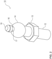
- FIG. 2 A preferred embodiment of the coupling bolt 10 is shown in Fig. 2
- the coupling bolt 10 is connected to the first component B1 via the fastening end 12.
- the fastening end 12 comprises a thread, a locking connection, an adhesive dome or another known construction for reliable connection to the first component B1.
- the fastening end 12 preferably comprises an external thread, which is screwed into a component opening (not shown) using a hexagon profile 13.
- the elongated construction of the coupling bolt 10 comprises a support section 14. After the connection to the holder 30 has been established, the holder 30 and the coupling bolt 10 support each other via the support section. This is how mechanical loads between the components B1, B2 are transferred.
- the holder 30 Adapted in its shape to the support area 14, the holder 30 preferably comprises a contact area 40 for this purpose, which is formed on a jacket surface 44 of the holder 30 facing the coupling bolt.
- the term jacket surface 44 follows from the shape of the contact area 40, since this jacket surface 44 at least partially surrounds the support section 14.
- the support section 14 is spherical.
- the matching contact area 40 is shaped like a ball socket or calotte, i.e. approximately complementary to the spherical support section 14. It is also preferred to design the support section 14 cylindrically, conically, elliptically or curved.
- the surface of the support section 14 facing the contact area 40 is preferably formed continuously in order to ensure that the contact area 40 slides and/or is supported on the support section 14. Therefore, for example, if the support section 14 is cylindrically designed, it is preferred that a cylinder longitudinal axis is arranged transversely to the longitudinal axis of the coupling bolt 10.
- a web 16 adjoins the support section 14.
- the web 16 connects the support section 14 and a holding head 18.
- the web 16 preferably has a round outer contour, although it can be designed to be angular in the same way.
- the web 16 is thinner, i.e. tapered, when measured transversely to the longitudinal axis of the coupling bolt 10. The holding head and the support section 14 thus protrude beyond the cross section of the web 16 in the radial or lateral direction.
- the web 16 is adapted to a keyhole 32 in the outer surface 44 of the holder 30.
- the keyhole 32 consists of an insertion section 36 which is larger or wider in diameter than the holding head 18 and which merges into a locking groove 38.
- the locking groove 38 is slightly wider than the web 16 so that the web 16 can be received in the locking groove 38.
- the web 16 is held in a form-fitting manner in the locking groove 38.
- the holding head 18 and the support section 14 extend in the radial or lateral direction over the width of the locking groove 38. Therefore, the web 16 cannot be released from the locking groove 38 in the axial direction of the coupling bolt 10.
- the web 16 preferably has an axial length which is defined by the adjacent holding head 18 and the adjacent support section 14.
- the length of the web 16 preferably corresponds to the thickness of the outer surface 44 at the closed end of the locking groove 38.
- the defined length of the web 16 serves to lock the coupling bolt 10 in the keyhole 32.
- the web 16 is or will be arranged at the closed end of the locking groove 38.
- the web 16 is already arranged at the end of the locking groove 38 after pivoting. It is also preferred that, in the case of a longer locking groove 38, a linear displacement of the web 16 towards the end of the locking groove 38 must take place after pivoting.
- the outer surface 44 is preferably held between an underside 17 of the holding head 18 facing the support section and the support section 14. Depending on the thickness and/or shape of the outer surface 44, the outer surface 44 is preferably clamped in this position.
- the support section 14 and the underside 17 each form an undercut to prevent the web 16 from becoming loose in the axial direction from the locking groove 38.
- the outer surface 44 is preferably shown, the shape of which is adapted to the support section 14.
- the side of the outer surface 44 facing the support section 14 forms the contact area 40.
- the keyhole 32 is cut out of the outer surface 44 from the insertion section 36 and the locking groove 38. Since the outer surface 44 does not run in one plane, the edge 34 of the keyhole 32 encloses a non-planar surface. Accordingly, the keyhole 32 does not run or lie in one plane. This means that inserting and locking the coupling bolt 10 in the keyhole 32 cannot be achieved by a straight-line movement alone. Rather, it is necessary for the coupling bolt 10 to be pivoted relative to the keyhole 32 after being linearly inserted or plugged into the insertion section 36. Therefore, the holding head 18 and the web 16 preferably move on an imaginary circular arc-like segment in order to be locked at the closed end of the locking groove 38.
- the outer surface 44 of the holder 30 and especially the radially inner contact surface 40 are designed in two stages. This ensures the clamping or a press fit of the holder 30 between the holding head 18 and the support section 14.
- the radially inner contact surface 40 has two different areas in its shape. In relation to a longitudinal axis of the coupling bolt 10 that can be arranged in the locking groove 38, the two different areas are arranged axially one behind the other in the form of a first 39 and a second surface segment 40a. This results in a two-stage contact surface 40, since it does not continue evenly.
- the first and the second radially inner surface segment 39, 40a are formed identically or differently in terms of their shape.
- the first 39 and the second surface segment 40a are spherical and spherical (see Fig. 5a , b ), spherical and conical (see Fig. 5c ), conical and spherical (see Fig. 5d ) or conical and conical (see Fig. 5e ). It is understood that further gradations can be arranged in the surface segments 39, 40a.
- the support section 14 it is preferred to provide the support section 14 as a polyhedron, a cylindrical roller transverse to the longitudinal axis L of the coupling bolt 10 or in another shape.
- the area with the first surface segment 39 forms a hat-shaped bulge in relation to the second surface segment 40a or its outer surface 44.
- This hat-shaped bulge projects in the radial direction beyond the outer diameter of the outer surface 44.
- the radial extent of the bulge with the radially inner first surface segment 39 is greater than the length of the web 16. Since the locking groove 38 preferably ends in the bulge, the holder 30 can only be locked by a press fit in the area of the bulge between the holding head 18 and the support section 14. In this press fit, the bulge with the radially inner first surface segment 39 is compressed in the longitudinal direction L of the coupling bolt 10. As a result, the bulge is spring-clamped between the undercut of the holding head 18 and the support section 14.
- the surface segments 39, 40a can be configured differently or similarly.
- the first 39 and the second surface segment 40a is spherical.
- the inner radius r 39 of the first surface segment 39 is smaller than an inner radius r 40a of the second surface segment 40a.
- the support section 14 of the coupling bolt 10 is preferably shaped as a sphere.
- the second surface segment 40a preferably has the same or a similar radius r 40a as the support section 14.
- the second surface segment 40a is conical.
- the first surface segment 39 is spherical.
- a cone angle 2 ⁇ and the inner radius r 39 are selected such that the first surface segment 39 forms the radial bulge in the direction of the longitudinal axis L of the coupling bolt 10, which can be arranged in a locked manner. While the conical surface segment 40a is supported on the support section 14, the bulge or the first surface segment 39 is forced under the undercut of the holding head 18. This ensures the press fit discussed above.
- the first surface segment 39 is conical. It also forms a radial bulge that protrudes from the lateral surface 44.
- the cone angle of the bulge or of the first surface segment 39 is selected such that the bulge protrudes radially from the lateral surface 44, characterized by the inner radius r 40a of the second surface segment.
- the second surface segment 40a is spherical with the inner radius r 40a .
- the inner radius r 40a corresponds to the radius of the sphere-like support section 14.
- a further preferred embodiment shows Fig. 5e
- the first 39 and the second surface segment 40a are conical.
- a cone angle 2 ⁇ of the first surface segment 39 is smaller than the cone angle 2 ⁇ of the second surface segment 40a.
- the bulge thus protrudes in the radial direction relative to the support section 14 in such a way that a press fit of the holder 30 between the holding head 18 and the support section 14 is ensured.
- the radially inner contact area 40 is not designed to be complementary to the support section 14.
- the contact area 40 is therefore not shaped as a ball socket complementary to the support section 14, but is divided into at least two stages into a first spherical surface segment 39 and a second spherical surface segment 40a. It is understood that more than two spherical surface segments can be provided in the contact area 40. In addition, it is preferred not to design the contact area 40 to be spherical.
- the lateral surface 44 in the region of the closed end of the locking groove 38 has a radial extension of the bulge that extends beyond a support surface.
- the contact area 40 is supported on the support section 14.
- the area 39 and thus preferably the lateral surface 44 is clamped or spring-loaded between the underside 17 of the holding head 18 and the support section 14. This supports the locking of the coupling bolt 10 in the holder 30 (see also Fig. 9 ).
- the holder 30 also comprises a fastening structure preferably on two opposite side surfaces.
- the fastening structure serves for clamping, gluing, locking or other suitable fastening of the holder 30 to the second component B2.
- fastening webs 42 are provided, which are inserted into a groove adapted to them (see Fig. 6 to 8 ) engage. The fastening webs 42 are clamped, locked, glued or similarly secured in this groove.
- FIG. 12 A preferred embodiment of the connection method is summarized in Fig. 12
- the individual sequences from Fig. 12b are enlarged in the Fig. 6 to 8 reproduced.
- the coupling bolt 10 is first inserted into the insertion section 36 of the keyhole 32 by means of a straight-line movement in the axial direction of the coupling bolt 10 (see arrow E in Fig. 6 , step S1).
- the coupling bolt 10 is inserted until the support section 14 rests against the holder 30 and the holding head 18 extends beyond the holder 30 (see Fig. 6 and 7 ).
- the insertion section 36 has a larger lateral or radial extent than the cross section of the holding head 18.
- the insertion is a relative movement between the coupling pin 10 and the holder 30. Therefore, either the coupling pin 10 or the holder 30 can move while the other part is at rest, or the coupling pin 10 and the holder 30 move simultaneously.
- Fig. 6 prefers the movement of the coupling bolt 10 into the keyhole 32, is shown in Fig. 12b the second component B2 with holder 30 is placed on the coupling bolt 10.
- the coupling bolt 10 is preferably pivoted (step S2) such that the holding head 18 is arranged at the closed end of the locking groove 38.
- the pivoting S takes place according to Fig. 7 and according to Fig. 12b around the support section 14 as a pivot point.
- the support section 14 is preferably designed as a ball, which supports the pivoting movement.
- the holder 30 is preferably transferred into a press fit between the holding head 18 and the support section 18. The press fit is essentially created by the compression of the bulge in the first surface segment 39, while the second surface segment 40 is supported entirely or partially on the support section 14.
- the first and the second component B1, B2 are preferably additionally connected to each other.
- This connection/connections is/are made according to various preferred embodiments of the present invention via at least one plug-in coupling 60 (see Fig. 11 ), a screw connection, a locking mechanism, a latching mechanism or another detachable connection (step S3).
- step S0 The above process steps are preceded by the fastening of the coupling bolt 10 and the holder 30 to the components B1, B2 (step S0).
Landscapes
- Engineering & Computer Science (AREA)
- General Engineering & Computer Science (AREA)
- Mechanical Engineering (AREA)
- Snaps, Bayonet Connections, Set Pins, And Snap Rings (AREA)
- Clamps And Clips (AREA)
- Pivots And Pivotal Connections (AREA)
- Connection Of Plates (AREA)
Description
- Die vorliegende Erfindung betrifft eine Kupplung, mit der ein erstes und ein zweites Bauteil miteinander verbindbar sind. Des Weiteren betrifft vorliegende Erfindung einen Kupplungsbolzen und einen Halter, die in ihrer Zusammenwirkung oben genannte Kupplung bilden. Zudem ist vorliegende Erfindung auf ein Verfahren zum Verbinden eines ersten und eines zweiten Bauteils mithilfe dieser formschlüssig arbeitenden Kupplung gerichtet.
- Im Stand der Technik sind verschiedene Steckkupplungen bekannt, die sich aus einem Kupplungselement und einem Kugelbolzen zusammensetzen. Das Kupplungselement weist eine Kugelpfanne auf, in die der Kugelkopf des Kugelbolzens einschnappt. Auf diese Weise wird eine Verbindung zwischen Kupplungselement und Kugelbolzen hergestellt. Da das Kupplungselement häufig aus elastomerem, also elastischem, Material besteht und/oder die Kugelpfanne in einem gewissen Grad bewegbar im Kupplungselement angeordnet ist, können mit diesen Steckkupplungen Schwingungen der Bauteile gedämpft werden.
-
EP 1 416 172 B1 beschreibt eine derartige Konstruktion einer Steckkupplung, die die Dämpfung von Bauteilschwingungen unterstützt. Zu diesem Zweck ist die den Kugelkopf aufnehmende Kugelpfanne an einem umfänglich angeordneten wellenförmigen Steg befestigt. Diese Wellenform des Stegs ermöglicht eine Bewegung der Kugelpfanne in beliebige Raumrichtungen, sodass Bewegungen zwischen den Bauteilen gedämpft werden. - Diese schwingungsdämpfenden Kupplungen haben aber den Nachteil, dass aufgrund der dämpfenden Materialeigenschaften von Kupplungselement und/oder Kugelbolzen die Haltekräfte zwischen Kupplungselement und Kugelbolzen limitiert sind. Aus diesem Grund sind derartige Steckkupplungen beispielsweise für mechanisch hochbelastete Verbindungen nicht geeignet. Dazu zählen u.a. großvolumige Verbrennungsmotoren oder Elektromotoren, für deren mechanische Schwingungen oder allgemein für deren mechanische Belastungen die Lösekräfte zwischen Kugelkopf und Kugelpfanne des Kupplungselements zu gering wären. Daraus folgt der Nachteil, dass beispielsweise Abdeckungen oder Verkleidungen im Motorraum aufgrund der dort vorhandenen Vibrationen aus ihrer Steckverbindung gelöst werden können.
- Um die Haltekräfte zwischen Kupplungselement und Kugelbolzen zu steigern, d.h. höhere Ausziehkräfte zu realisieren, beschreibt
DE 10 2013 102 197 A1 eine andere Kupplungskonstruktion. Der hier verwendete Kugelbolzen greift in die Konstruktion eines Kupplungselements ein, deren einzelne Haltestege entgegen einer Einsetzrichtung des Kugelbolzens in die Kugelpfanne geneigt sind. Aufgrund der Neigung dieser Stege und aufgrund des Angriffspunkts der einzelnen Stege am Kugelkopf verhindern die Stege ein Herauslösen des Kugelkopfs aus der Kugelpfanne mit geringen Ausziehkräften. Denn während einer Auszugsbewegung werden die Stege gestaucht und/oder in Richtung der Einsetzöffnung des Kupplungselements bewegt. Aufgrund dieser Schwenkbewegung der Stege wird die Öffnung des Kupplungselements teilweise blockiert, was ein Herauslösen des Kugelkopfs verhindert. Trotz der hohen Auszugskräfte dieser Kupplung ist es von Nachteil, dass die Verbindung zwischen Kupplungselement und Kugelkopf nicht zerstörungsfrei gelöst werden kann. Somit werden beispielsweise Verkleidungen im Motorbereich zwar verlässlich gehalten, aber jedes Entfernen eines Verkleidungsteils zerstört das Kupplungselement. Aus diesem Grund muss jedes Mal das Kupplungselement ersetzt werden, was zusätzlichen Arbeits- und Kostenauf wand mit sich bringt. - Eine Steckhalterung für einen oberen Befestigungspunkt eines hängend montierbaren Bauteils ist in
DE 10 2010 000 260 A1 beschrieben. Die Steckhalterung umfasst ein Gehäuse mit einer Öffnung, die eine Mittelachse hat, und einen Haltebolzen des Bauteils mit einem mit einer Nut versehenen Ende, das in das Gehäuse einführbar und darin lösbar verriegelbar ist. Die Öffnung ist schräg in dem Gehäuse unter einem spitzen Winkel gegen die Senkrechte angeordnet. Zu Montage des Bauteils ist der Haltebolzen entweder in der Mittelachse oder in der Senkrechten in die Öffnung einführbar und dann durch Einrasten eines als ein Federelement ausgebildeten Anteils der Öffnung in die Nut verriegelbar. Zur Demontage des Bauteils wird der Haltebolzen um den Randteil in die Mittelachse geschwenkt und dadurch entriegelt und kann dann aus der Öffnung herausgezogen werden. - Es ist daher die Aufgabe vorliegender Erfindung, eine zum Stand der Technik alternative Kupplung bereitzustellen, die ausreichend hohe Lösekräfte realisiert und damit mechanisch belastbar ist. Gleichzeitig soll die Kupplung aber auch zerstörungsfrei lösbar sein, um gerade bei Wartungsarbeiten die erforderliche Flexibilität zu gewährleisten.
- Die obige Aufgabe wird durch einen Halter für einer Kupplung gemäß dem unabhängigen Patentanspruch 1, eine Kupplung, mit der ein erstes und ein zweites Bauteil miteinander verbindbar sind, gemäß dem abhängigen Patentanspruch 3 sowie durch ein Verfahren zum Verbinden eines ersten und eines zweiten Bauteils mithilfe der Kupplung gemäß dem unabhängigen Patentanspruch 12 gelöst. Vorteilhafte Ausgestaltungen und Weiterentwicklungen vorliegender Erfindung gehen aus der folgenden Beschreibung, den begleitenden Zeichnungen und den anhängenden Ansprüchen hervor.
- Die erfindungsgemäße Kupplung, mit der ein erstes und ein zweites Bauteil miteinander verbindbar sind, weist die folgenden Merkmale auf einen Kupplungsbolzen, der ein Befestigungsende, einen Haltekopf und einen dazwischen angeordneten Stützabschnitt umfasst, in der der Haltekopf und der Stützabschnitt über einen gegenüber dem Haltekopf verjüngten Steg miteinander verbunden sind und in der das Befestigungsende am ersten Bauteil befestigbar ist, einen Halter mit einem Schlüsselloch und einem Anlagebereich, in dem ein Rand des Schlüssellochs eine nicht-ebene Fläche einschließt, der Kupplungsbolzen über eine Steck-Schwenk-Bewegung in dem Schlüsselloch formschlüssig verriegelbar ist und der Halter über eine Befestigungsstruktur an dem zweiten Bauteil befestigbar ist.
- Die Verbindung zwischen Kupplungsbolzen und Halter wird nicht allein durch eine geradlinige Steckbewegung hergestellt. Vielmehr findet hier eine Kombination einer linearen und einer Schwenkbewegung statt, um eine formschlüssige Verbindung zwischen dem Kupplungsbolzen und dem Schlüsselloch des Halters herzustellen. Zu diesem Zweck weist der Kupplungsbolzen einen Haltekopf auf, der sich im Schlüsselloch verriegelt, vorzugsweise nachdem die Schwenkbewegung abgeschlossen ist. Der ebenfalls im Kugelbolzen vorgesehene Stützabschnitt liegt bevorzugt zumindest teilweise an dem Halter an, sobald der Haltekopf im Schlüsselloch eingesetzt und/oder nachdem er in diesem verriegelt worden ist. Damit werden mechanische Belastungen zwischen dem Stützabschnitt des Kupplungsbolzens und dem Anlagebereich des Halters und daher zwischen den Bauteilen übertragen. Der Anlagebereich erstreckt sich nämlich in der Umgebung des Schlüssellochs, sodass die Verriegelung des Haltekopfs im Schlüsselloch den Stützabschnitt zur Anlage im Anlagebereich bringt. Die formschlüssige Verbindung zwischen Schlüsselloch und Haltekopf und somit zwischen Halter und Kupplungsbolzen widersteht maximalen Auszugskräften. Denn diese maximalen Auszugskräfte aus dem Schlüsselloch sind durch die Materialstabilität des Halters und/oder des Kupplungsbolzens bestimmt, da nur ein den Halter oder den Kupplungsbolzen zerstörendes Ausziehen möglich wäre. Da der Kupplungsbolzen über sein Befestigungsende mit dem ersten Bauteil verbunden ist und der Halter über seine Befestigungsstruktur am zweiten Bauteil befestigt ist, wird durch die Verbindung zwischen Kupplungsbolzen und Halter gleichzeitig eine verlässliche Verbindung zwischen erstem und zweitem Bauteil realisiert.
- Gemäß einer bevorzugten Ausführungsform vorliegender Erfindung umfasst das Schlüsselloch einen Einsetzabschnitt und eine Verriegelungsnut, in der der Einsetzabschnitt einen Durchgangsbereich für den Haltekopf des Kupplungsbolzens bildet, und eine Breite der Verriegelungsnut geringer ist als ein Durchmesser des Haltekopfs und größer als eine Dicke des verjüngten Stegs.
- Das bereits oben beschriebene Schlüsselloch schließt mit seinem Rand eine nicht-ebene Fläche ein. Das bedeutet, dass das Schlüsselloch in einem Flächenbereich des Halters angeordnet ist, der nicht in einer Ebene liegt. Ein derartiger Flächenbereich wird beispielsweise durch eine Mantelfläche eines Kugelsegments, eine Kugelpfanne, eine konische Mantelfläche oder durch eine beliebig krummlinig gewölbte Mantelfläche gebildet. Das aus dieser Mantelfläche ausgeschnittene Schlüsselloch setzt sich aus dem beliebig geformten Einsetzabschnitt und der sich daran anschließenden Verriegelungsnut zusammen. Der Einsetzabschnitt muss eine ausreichende Ausdehnung haben, damit der Haltekopf durch diesen Einsetzabschnitt hindurchgeführt werden kann. Andererseits muss der Einsetzabschnitt ausreichend schmal sein, damit der Stützabschnitt gerade nicht den Einsetzabschnitt durchlaufen kann.
- Vorteilhafterweise sind der Haltekopf und der Stützabschnitt durch den verjüngten Steg voneinander beabstandet, dessen Breite an die Breite der Verriegelungsnut angepasst ist. Da die Verriegelungsnut gerade ausreichend breit ist, um den verjüngten Steg aufnehmen zu können, wird der Kupplungsbolzen in der Verriegelungsnut gehalten. Denn der Haltekopf und der Stützabschnitt sind jeweils in ihrer lateralen Ausdehnung breiter als die Breite der Verriegelungsnut, sodass der Kupplungsbolzen und im Speziellen der verjüngte Steg nur noch durch eine Bewegung entgegen der Einsetzrichtung aus der Verriegelungsnut gelöst werden kann. Aufgrund dieser Größenverhältnisse von Haltekopf, verjüngtem Steg und Stützabschnitt im Vergleich zur Verriegelungsnut und zum Einsetzabschnitt ergibt sich eine formschlüssige Verbindung zwischen dem Kupplungsbolzen und dem Halter. Diese formschlüssige Verbindung ist durch wirkende mechanische Kräfte nur dann lösbar, wenn das Material des Kupplungsbolzens und/oder des Halters versagt. Dementsprechend sorgt eine gezielte Materialwahl für Kupplungsbolzen und Halter vorzugsweise für die gewünschte Stabilität der Kupplung und somit der Verbindung zwischen dem ersten und dem zweiten Bauteil. In diesem Zusammenhang besteht der Kupplungsbolzen vorzugsweise aus Metall, während der Halter ebenfalls aus Metall oder aus einem geeigneten Kunststoff mit einer passenden Shore-Härte und geringer Elastizität aufgebaut ist. In gleicher Weise sind auch andere Materialien oder Materialkombinationen einsetzbar, sofern damit die gewünschte Stabilität erzielt wird.
- Gemäß einer weiteren bevorzugten Ausführungsform vorliegender Erfindung ist der Anlagebereich des Halters an die Form des Stützabschnitts des Kupplungsbolzens angepasst, sodass sich der Kupplungsbolzen und der Halter im verriegelten Zustand zumindest teilweise aneinander abstützen. Erfindungsgemäß bevorzugt weist der Anlagebereich die Form einer Kugelpfanne auf, in deren Mantelfläche das Schlüsselloch ausgebildet ist.
- Sofern mechanische Belastungen an erstem und/oder zweitem Bauteil auftreten, werden diese über die Kupplung zwischen den beiden Bauteilen übertragen. Da der Stützabschnitt des Kupplungsbolzens am Anlagebereich des Halters zumindest teilweise anliegt, erfolgt die Übertragung mechanischer Lasten, wie beispielsweise Bauteilschwingungen, über den Bereich der aneinander anliegenden Flächen von Anlagebereich und Stützabschnitt. Um dabei die mechanische Belastung von Halter und Kupplungsbolzen möglichst gering zu halten, ist eine große Kontaktfläche zwischen Anlagebereich und Stützabschnitt bevorzugt. Diese wird gemäß einer bevorzugten Ausführungsform vorliegender Erfindung dadurch realisiert, dass der Anlagebereich komplementär zum Stützabschnitt des Kupplungsbolzens ausgebildet ist. Eine bevorzugte Ausführungsform des Stützabschnitts nutzt eine zwischen dem Befestigungsende und dem Haltekopf angeordnete Kugel, die in einen zumindest teilweise oder vollständig als Kugelpfanne ausgeformten Anlagebereich des Halters eingreift. Es ist ebenfalls bevorzugt, andere aneinander angepasste Formgebungen für Stützabschnitt und Anlagebereich zu nutzen, wie beispielsweise eine konische oder zylindrische Form des Stützabschnitts und einen entsprechend komplementär dazu ausgebildeten Anlagebereich. Es ist weiterhin bevorzugt, einen konisch geformten Anlagebereich mit einem kugelförmigen Stützabschnitt zu kombinieren.
- Gemäß einer weiteren bevorzugten Ausführungsform vorliegender Erfindung weist der Halter seitlich angeordnete Befestigungsstege auf, mit denen der Halter am zweiten Bauteil befestigbar, vorzugsweise verrastbar oder klemmbar, ist. Alternativ dazu sind am Halter vorzugsweise seitliche Stege angeordnet, die in entsprechenden Nuten am zweiten Bauteil aufnehmbar sind. Diese Stege werden in diese Nuten eingeklemmt, verklebt oder anderweitig verlässlich befestigt.
- Weiterhin bevorzugt ist der Stützabschnitt des Kugelbolzens kugelförmig ausgebildet, wie es oben bereits diskutiert worden ist. Der Haltekopf bildet vorzugsweise mit dem verjüngten Steg eine pilzförmige Struktur, die das Verriegeln des Kupplungsbolzens in der Verriegelungsnut unterstützt.
- Gemäß der Erfindung ist der Anlagebereich der Kupplung bezogen auf eine Längsachse eines im Schlüsselloch verriegelt anordenbaren Kupplungsbolzens zumindest zweistufig ausgebildet, sodass der Anlagebereich zwischen dem Haltekopf und dem Stützabschnitt des Kupplungsbolzens mechanisch verspannbar ist.
- Im Kupplungsbolzen bilden der Haltekopf und der mit ihm über einen Steg verbundene Stützabschnitt jeweils einen Hinterschnitt in Längsrichtung des Kupplungsbolzens, sodass sich der Halter, insbesondere der Anlagebereich, in entgegengesetzten Richtungen am Haltekopf und dem Stützabschnitt abstützen kann. Dies eröffnet die Möglichkeit, ergänzend zur formschlüssigen Verbindung über das Schlüsselloch im Anlagebereich einen Presssitz des Anlagebereichs zwischen Haltekopf und Stützabschnitt zu realisieren. Zu diesem Zweck ist der Anlagebereich zweistufig ausgebildet. Eine erste Stufe des Anlagebereichs gewährleistet das Anliegen und Abstützen des Anlagebereichs am Stützabschnitt des Kupplungsbolzens. Eine zweite Stufe des Anlagebereichs schließt sich in axialer Richtung des verriegelt anordenbaren Kupplungsbolzens an die erste Stufe des Anlagebereichs an. So ist bevorzugt die erste Stufe des Anlagebereichs konisch ausgebildet, während die zweite Stufe des Anlagebereichs eine kugelförmige Gestalt aufweist. Es ist ebenfalls bevorzugt, beide Stufen des Anlagebereichs konisch, kugelförmig oder anderweitig auszubilden, solange das Abstützen an Haltekopf und Stützabschnitt gewährleistet ist. Die beiden Stufen des Anlagebereichs sind in ihrer Ausdehnung parallel zur Längsachse des verriegelt anordenbaren Kupplungsbolzens derart ausgebildet, dass sie nur über eine in Längsrichtung des Kupplungsbolzens stattfindende Kompression zwischen dem Haltekopf und dem Stützabschnitt in einem Presssitz anordenbar sind. Aufgrund des Presssitzes wird der Anlagebereich, der sich am Haltekopf abstützt, gegen den Stützabschnitt gedrückt. Verriegeln des Kupplungsbolzens bedeutet in diesem Zusammenhang ein Anordnen des Kupplungsbolzens am geschlossenen Ende der Verriegelungsnut.
- Gemäß einer weiteren bevorzugten Ausführungsform besteht der Anlagebereich der Kupplung bzw. des Halters aus mindestens einem ersten und einem zweiten Flächensegment, die jeweils dem Stützabschnitt oder allgemein dem Kupplungsbolzen zugewandt sind und die zumindest teilweise symmetrisch um den verriegelt anordenbaren Kupplungsbolzen angeordnet sind.
- Wie bereits oben angedeutet worden ist, sind die Flächensegmente vorzugsweise unterschiedlich geformt. Ihre Anlagefläche ist aber bevorzugt dem Stützabschnitt des Kupplungsbolzens zugewandt, während sich im verriegelten Zustand eine Rück- oder Seitenfläche des ersten Flächensegments am Haltekopf abstützt. Diese Art der Anordnung der Flächensegmente dient dazu, dass im komprimierten Zustand des Anlagebereichs bzw. nach Verriegeln des Kupplungsbolzens im Schlüsselloch eine möglichst große Fläche der Flächensegmente der Kupplung am Stützabschnitt anliegt. Die vorzugsweise in ihrer Symmetrie an den Kupplungsbolzen angepassten Flächensegmente gewährleisten eine gewisse Flexibilität beim Einsetzen des Kupplungsbolzens in das Schlüsselloch. Auf diese Weise ist keine genaue Vororientierung des Kupplungsbolzens bezogen auf die Flächensegmente erforderlich.
- Gemäß einer weiteren bevorzugten Ausführungsform vorliegender Erfindung sind die Flächensegmente kugelförmig ausgebildet. Zudem ist bevorzugt ein Radius des ersten kugelförmigen Flächensegments kleiner als ein Radius des zweiten kugelförmigen Flächensegments. Zudem ist bevorzugt das erste kugelförmige Flächensegment angrenzend an das Schlüsselloch angeordnet.
- Das zweite kugelförmige Flächensegment ist vorzugsweise in seiner Größe an den Stützabschnitt des Kupplungsbolzens angepasst. Gemäß einer Ausführungsform vorliegender Erfindung bildet das zweite kugelförmige Flächensegment eine komplementär zum kugelförmig ausgebildeten Stützabschnitt ausgebildete Kugelpfanne. Das erste kugelförmige Flächensegment sitzt hutförmig oder ähnlich einem Kragen auf dem zweiten kugelförmigen Flächensegment. Daher steht es aus der Umfangsfläche des zweiten kugelförmigen Flächensegments radial auswärts vor und bildet bevorzugt eine Ausbuchtung, in der das Schlüsselloch ausgebildet ist. Die radiale Ausdehnung der Ausbuchtung beginnend an der gedacht in Umfangsrichtung verlängerten inneren Anlagefläche des zweiten Flächensegments ist vorzugsweise größer als die Länge des verbindenden Stegs zwischen dem Haltekopf und dem Stützabschnitt. Somit ist der Kupplungsbolzen nur im Schlüsselloch verriegelbar, wenn das erste und zweite Flächensegment in Längsrichtung des Kupplungsbolzens komprimiert werden, um den Presssitz des Anlagebereichs zwischen Haltekopf und Stützabschnitt des Kupplungsbolzens zu realisieren.
- Gemäß einer weiteren bevorzugten Ausführungsform vorliegender Erfindung sind das erste Flächensegment konisch oder kugelförmig und das zweite Flächensegment konisch oder kugelförmig ausgebildet, wobei bei zwei konischen Flächensegmenten ein Konuswinkel des ersten Flächensegments kleiner ist als ein Konuswinkel des zweiten Flächensegments. In Analogie zu den oben beschriebenen kugelförmig ausgebildeten Flächensegmenten sind ebenfalls konisch geformte Flächensegmente oder konisch und kugelförmig geformte Flächensegmente miteinander kombinierbar.
- In diesem Zusammenhang ist zu gewährleisten, dass jeweils das erste Flächensegment, egal ob konisch oder kugelförmig ausgebildet, in seiner Größe derart an das erste Flächensegment angepasst sein muss, dass es hutartig oder kragenähnlich auf dem zweiten Flächensegment angeordnet ist. Diese Formgebung stellt sicher, dass für den Presssitz des Anlagebereichs am verriegelt angeordneten Kupplungsbolzen gerade das erste Flächensegment in axialer Richtung des Kupplungsbolzens komprimiert werden muss, um es zwischen Haltekopf und Stützabschnitt des Kupplungsbolzens anordnen zu können. Daraus folgt, dass ein Radius eines kugelförmigen ersten Flächensegments oder ein Konuswinkel eines konischen ersten Flächensegments nicht größer oder gleich einem Radius eines kugelförmigen zweiten Flächensegments oder einem Konuswinkels eines konischen zweiten Flächensegments sein darf.
- Gemäß einer weiteren bevorzugten Ausführungsform vorliegender Erfindung ist das erste Flächensegment kugelförmig ausgebildet mit einem Durchmesser, der kleiner ist als ein Durchmesser des Stützabschnitts, und das zweite Flächensegment ist kegelstumpfartig geformt, sodass der Stützabschnitt durch das zweite Flächensegment tangential angreifbar ist.
- Vorliegende Erfindung umfasst zudem den Kupplungsbolzen für die oben genannte Kupplung. Der Kupplungsbolzen umfasst das Befestigungsende, den Haltekopf und den dazwischen angeordneten Stützabschnitt, in den der Haltekopf und der Stützabschnitt über einen gegenüber dem Haltekopf verjüngten Steg miteinander verbunden sind und das Befestigungsende an einem Bauteil befestigbar ist. Bevorzugt ist der Stützabschnitt kugelförmig ausgebildet und der Haltekopf bildet mit dem verjüngten Steg eine pilzförmige Struktur. Die Vorteile der einzelnen Komponenten sowie ihr Zusammenwirken mit dem Halter wurden oben bereits beschrieben. Im Hinblick auf das Befestigungsende weist dieses vorzugsweise ein Gewinde, einen Schnappverschluss, einen Bajonettverschluss oder eine andere Struktur zur verlässlichen Befestigung des Kupplungsbolzens an oder in dem Bauteil auf.
- Vorliegende Erfindung umfasst ebenfalls den bereits oben erwähnten Halter der Kupplung. Dieser weist ein Schlüsselloch und einen Anlagebereich auf, in dem ein Rand des Schlüssellochs eine nicht-ebene Fläche einschließt und der Halter über eine Befestigungsstruktur an einem Bauteil befestigbar ist. Ebenfalls erfindungsgemäß bevorzugt umfasst der Halter seitlich angeordnete Federstege oder Befestigungsstege, mit denen der Halter an einem Bauteil verrastbar, klemmbar oder allgemein befestigbar ist. Vorzugsweise greifen diese Befestigungsstege in konstruktiv daran angepasste Befestigungsnuten oder andere Konstruktionen ein oder an diese an, um den Halter verlässlich am Bauteil festzulegen. Des Weiteren weist der Halter die gleichen konstruktiven und funktionellen Eigenschaften auf, wie sie oben in Zusammenhang mit der Kupplung diskutiert worden sind. Entsprechend ist der Anlagebereich in Richtung einer Längsachse des im Schlüsselloch verriegelt anordenbaren Kupplungsbolzens zumindest zweistufig ausgebildet, sodass der Anlagebereich zwischen dem Haltekopf und dem Stützabschnitt des Kupplungsbolzens mechanisch verspannbar ist. Zudem besteht erfindungsgemäß bevorzugt der Anlagebereich aus mindestens einem ersten und einem zweiten Flächensegment, die symmetrisch um den im Schlüsselloch verriegelt anordenbaren Kupplungsbolzen angeordnet sind. Gemäß einer weiteren bevorzugten Ausführungsform des erfindungsgemäßen Halters sind das erste Flächensegment konisch oder kugelförmig und das zweite Flächensegment konisch oder kugelförmig ausgebildet, wobei bei zwei konischen Flächensegmenten ein Konuswinkel des ersten Flächensegments kleiner ist als ein Konuswinkel des zweiten Flächensegments. Eine weitere erfindungsgemäß bevorzugte Ausführungsform des Halters umfasst das erste Flächensegment in einer kugelförmigen Ausbildung mit einem Durchmesser, der kleiner ist als ein Durchmesser des Stützabschnitts des Kupplungsbolzens und in der das zweite Flächensegment kegelstumpfartig geformt ist und tangential am Stützabschnitt angreift.
- Vorliegende Erfindung umfasst ebenfalls ein Verfahren zum Verbinden eines ersten und eines zweiten Bauteils mithilfe einer Kupplung, vorzugsweise einer formschlüssig arbeitenden Kupplung. Eine derartige Kupplung entspricht gemäß einer Ausführungsform vorliegender Erfindung der bereits oben beschriebenen Kupplung. Zur Realisierung des erfindungsgemäßen Verfahrens ist das erste Bauteil über ein Befestigungsende mit einem Kupplungsbolzen verbunden, der einen Haltekopf, einen Stützabschnitt und einen dazwischen angeordneten verjüngten Steg aufweist. Das zweite Bauteil weist einen Halter mit einem Schlüsselloch und einem Anlagebereich auf, in dem ein Rand des Schlüssellochs eine nicht-ebene Fläche einschließt. Das Verfahren zum Verbinden des ersten und des zweiten Bauteils umfasst folgende Schritte: Einstecken des Haltekopfs in einen Einsetzabschnitt des Schlüssellochs, sodass der Stützabschnitt am Halter anliegt, und Schwenken des Kupplungsbolzens relativ zum Halter, sodass der verjüngte Steg des Schlüssellochs zwischen dem Haltekopf und dem Stützabschnitt zumindest formschlüssig in einer Verriegelungsnut des Schlüssellochs angeordnet ist.
- Aufgrund der Formgebung des Kupplungsbolzens und des Halters und aufgrund der Verbindung des Kupplungsbolzens mit dem ersten Bauteil und des Halters mit dem zweiten Bauteil liegt eine formschlüssige Verbindung zwischen dem ersten und dem zweiten Bauteil vor. Eine derartige formschlüssige Verbindung widersteht hohen mechanischen Belastungen, da im Wesentlichen die Materialbeschaffenheit von Kupplungsbolzen und Halter die Festigkeit der Verbindung bestimmt.
- Des Weiteren ist es von Vorteil, dass die formschlüssige Verbindung nur über eine bestimmte Kombination von Bewegungen herstellbar ist. Im Speziellen wird der Kupplungsbolzen über eine geradlinige Steckbewegung und eine nachfolgende Schwenkbewegung in dem Schlüsselloch des Halters verriegelt. Ist vorzugsweise der Halter mit einer Motorabdeckung oder einem ähnlichen Teil verbunden, lässt sich dieses in einer räumlichen Schrägorientierung auf den Kupplungsbolzen aufsetzen und dann durch eine nachfolgende Schwenkbewegung am Kupplungsbolzen verriegeln. Dies eröffnet die Möglichkeit, dass eine derartige Verkleidung oder ein anderes Bauteil nur dann wieder von dem Kupplungsbolzen lösbar ist, wenn in umgekehrter Reihenfolge die oben genannten Relativbewegungen zwischen Kupplungsbolzen und Halter, d. h. die Schwenkbewegung und die geradlinige Bewegung, ausgeführt werden. Die Verbindung ist somit nicht durch ein geradliniges Herausziehen des Kupplungsbolzens aus dem Halter lösbar. Wird das zweite Bauteil nach Beendigung der Schwenkbewegung beispielsweise in einer zweiten Steckkupplung oder mithilfe eines weiteren Verbindungselements in dieser Position fixiert, dann garantiert die erfindungsgemäße Kupplung eine belastbare und verlässliche Fixierung des ersten und zweiten Bauteils aneinander.
- Erfindungsgemäß bevorzugt umfasst das Verbindungsverfahren den weiteren Schritt: Federvorspannen des Stützabschnitts des Kupplungsbolzens gegen den Anlagebereich des Halters, in dem der verjüngte Steg in die Verriegelungsnut eingeschwenkt wird. Gemäß einer weiteren bevorzugten Ausführungsform des erfindungsgemäßen Verfahrens ist der Stützabschnitt kugelförmig ausgebildet. Der Stützabschnitt wird zudem in dem kugelpfannenähnlichen Anlagebereich, der vorzugsweise konisch oder kugelförmig ausgebildet ist, aufgenommen, sodass Kräfte zwischen dem Kupplungsbolzen und dem Halter flächig übertragen werden.
- Des Weiteren sind im Halter die oben diskutierten ersten und zweiten Flächensegmente vorgesehen. Basierend auf der zweistufigen Formgebung des Anlagebereichs, insbesondere der Flächensegmente, wird ein Presssitz des Halters zwischen dem Haltekopf und dem Stützabschnitt des Kupplungsbolzens hergestellt.
- Es ist des Weiteren bevorzugt, eine weitere Verbindung zwischen dem ersten und dem zweiten Bauteil am Ende der Schwenkbewegung herzustellen, vorzugsweise über eine Steckkupplung, wie es oben bereits erläutert worden ist.
- Vorliegende Erfindung umfasst zudem ein erstes und ein zweites Bauteil, die zumindest über eine Kupplung gemäß den oben beschriebenen Ausführungsformen miteinander verbunden sind. Erfindungsgemäß bevorzugt ist das erste und zweite Bauteil zusätzlich über eine Steckkupplung miteinander verbunden.
- Wie bereits im Zusammenhang mit den bevorzugten Verfahrensschritten des Verfahrens zum Verbinden des ersten und zweiten Bauteils erläutert worden ist, stellt die erfindungsgemäße Steckkupplung eine belastbare Verbindung zwischen dem ersten und zweiten Bauteil her. Die zweite Steckkupplung gewährleistet neben einem zusätzlichen mechanischen Halt der beiden Bauteile aneinander eine Sicherung, die ein Lösen der formschlüssigen Verbindung in der erfindungsgemäßen Kupplung verhindert.
- Die bevorzugten Ausführungsformen vorliegender Erfindung werden unter Bezugnahme auf die begleitenden Zeichnungen näher erläutert. Es zeigen:
- Fig. 1
- eine perspektivische Darstellung einer bevorzugten Ausführungsform der erfindungsgemäßen Kupplung in Verbindung mit dem zweiten Bauteil,
- Fig. 2
- eine perspektivische Darstellung des Kupplungsbolzens aus
Fig. 1 , - Fig. 3
- eine perspektivische Darstellung des Halters aus
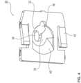
Fig. 1 , - Fig. 4
- eine perspektivische Ansicht des Halters aus
Fig. 1 von unten, - Fig. 5a - e
- bevorzugte Konfigurationen des Halters in schematischer Darstellung mit und ohne Kupplungsbolzen
- Fig. 6
- eine Seitenansicht des bevorzugten Kupplungsbolzens und des bevorzugten Halters vor dem Einsetzen des Kupplungsbolzens in den Halter,
- Fig. 7
- eine Seitenansicht des bevorzugten Kupplungsbolzens und des bevorzugten Halters nachdem der Kupplungsbolzen in den Aufnahmebereich des Halters eingesetzt worden ist,
- Fig. 8
- eine Seitenansicht des bevorzugten Kupplungsbolzens und des bevorzugten Halters nachdem der Kupplungsbolzen in der Verriegelungsnut verriegelt worden ist,
- Fig. 9
- eine vergrößerte Ausschnittsdarstellung der Verbindung zwischen Kupplungsbolzen und Halter aus
Fig. 7 , - Fig. 10
- eine perspektivische Ansicht der bevorzugten Ausführungsform der erfindungsgemäßen Kupplung bestehend aus Kupplungsbolzen und Halter,
- Fig. 11
- eine schematische Darstellung der Verwendung der erfindungsgemäßen Kupplung in Kombination mit einem ersten und einem zweiten Bauteil und
- Fig. 12
- ein Flussidagramm einer bevorzugten Ausführungsform des Verbindungsverfahrens des ersten und zweiten Bauteils mithilfe der Kupplung (
Fig. 12a ) und eine sequentielle Darstellung des Verbindungsverfahrens mithilfe des bevorzugten Kupplungsbolzens und des bevorzugten Halters in Kombination mit dem zweiten Bauteil (Fig. 12b ). - Die erfindungsgemäße Kupplung dient der Befestigung eines ersten Bauteils B1 und eines zweitens Bauteils B2 aneinander. Im weitesten Sinne handelt es sich hier um eine Steckkupplung. Während herkömmliche Steckkupplungen hauptsächlich einen Presssitz - also eine kraftschlüssige Verbindung - realisieren, nutzt vorliegende Erfindung eine formschlüssige Verbindung zur Bereitstellung einer verlässlichen Verbindung zwischen den Bauteilen B1, B2. Gemäß bevorzugter Ausführungsformen vorliegender Erfindung wird der realisierte Formschluss durch eine zusätzliche kraftschlüssige Verbindung unterstützt.
- Eine perspektivische Darstellung einer bevorzugten Ausführungsform der erfindungsgemäßen Kupplung zeigen die
Figuren 1 und9 . Die einzelnen Komponenten der Kupplung und ihre bevorzugte Ausgestaltung sind in denFiguren 2 bis 8 veranschaulicht. - Die Kupplung dient der bevorzugten formschlüssigen Verbindung zwischen dem ersten Bauteil B1 und dem zweiten Bauteil B2. Zur Herstellung der Verbindung wird ein Kupplungsbolzen 10 mit seinem Befestigungsende 12 im ersten Bauteil B1 befestigt. Ein Halter 30, mit dem der Kupplungsbolzen 10 verbunden wird, wird am zweiten Bauteil B2 befestigt. Dazu ist vorzugsweise am Halter 30 eine laterale Befestigungsstruktur vorgesehen.
- In einer bevorzugten Anwendung stellt das erste Bauteil B1 einen Motorblock oder eine Trägerstruktur in einem Fahrzeug dar. Das zweite Bauteil B2 wird durch eine Abdeckung, wie beispielsweise ein Motorcover oder dergleichen, gebildet. Mithilfe der erfindungsgemäßen Kupplung ist die Abdeckung B2 an der Trägerstruktur oder dem Motorblock B1 durch eine Steck-Schwenk-Bewegung befestigbar, wie es schematisch in
Fig. 11 gezeigt ist. Dazu zeigtFig. 11a ein bevorzugtes Einstecken des Kupplungsbolzens 10 in den Halter 30, in dem das erste B1 und das zweite Bauteil B2 bzw. der Kupplungsbolzen 10 und der Halter 30 relativ aufeinander zu bewegt werden. Dieses bevorzugte Einstecken des Kupplungsbolzens 10 in den Halter 30, das auch als geradlinige Relativbewegung bezeichnet werden kann, führt zu einer Verbindungsvorbereitung zwischen den beiden Bauteilen B1, B2. - Nachdem der Kupplungsbolzen 10 in den Halter 30 eingesetzt worden ist, wird der Halter 30 relativ zum Kupplungsbolzen 10 oder das zweite Bauteil B2 relativ zum ersten Bauteil B1 verschwenkt (siehe
Fig. 11b ). Basierend auf dieser Steck-Schwenk-Bewegung zwischen dem Halter 30 und dem Kupplungsbolzen 10 entsteht eine formschlüssige Verbindung, die zerstörungsfrei nur über die Umkehrung der Schwenkbewegung und der geradlinigen Relativbewegung oder Steckbewegung gelöst werden kann. Sofern diese die Verbindung lösende Umkehrung der Steck-Schwenk-Bewegung vermieden wird, liegt eine versagensstabile Verbindung zwischen dem ersten B1 und dem zweiten Bauteil B2 vor. - Um nach Herstellung der Verbindung zwischen dem ersten B1 und dem zweiten Bauteil B2 die Umkehrung der Schwenkbewegung zu vermeiden, ist vorzugsweise eine Steckkupplung zwischen Bauteil B1 und Bauteil B2 vorgesehen. Derartige Steckkupplungen oder andere Verbindungen sind im Stand der Technik bekannt. Wird vorzugsweise ein Kugelbolzen mit Steckkupplung eingesetzt, ist es bevorzugt, diese einander gegenüberliegend in einem von der erfindungsgemäßen Kupplung beabstandeten Bereich der Bauteile B1, B2 anzuordnen. Bevorzugte Positionen sind in
Fig. 11a durch Kreuze schematisch angedeutet. Sobald die zusätzliche Verbindung, vorzugsweise durch zusätzliche Steckkupplungen, zwischen den Bauteilen B1, B2 hergestellt ist, wird dadurch eine lösende Schwenkbewegung in entgegengesetzter Richtung als inFig. 11b gezeigt, verhindert. - Die Stabilität und mechanische Belastbarkeit der Kupplung ist unter anderem durch die Materialeigenschaften des Kupplungsbolzens 10 und des Halters 30 bestimmt. Daher besteht der Kupplungsbolzen 10 vorzugsweise aus Metall oder Keramik oder einem stabilen Kunststoff mit oder ohne Faserverstärkung oder aus einer Kombination dieser Materialien. Der Halter 30 besteht vorzugsweise aus einem stabilen, bevorzugt federnden, Kunststoff mit oder ohne Faserverstärkung oder einem Metall oder aus einer Kombination davon.
- Eine bevorzugte Ausführungsform des Kupplungsbolzens 10 ist in
Fig. 2 gezeigt. Der Kupplungsbolzen 10 wird über das Befestigungsende 12 mit dem ersten Bauteil B1 verbunden. Zu diesem Zweck umfasst das Befestigungsende 12 ein Gewinde, eine Rastverbindung, einen Klebdom oder eine andere bekannte Konstruktion zur verlässlichen Anbindung an das erste Bauteil B1. GemäßFig. 2 umfasst das Befestigungsende 12 bevorzugt ein Außengewinde, das mithilfe eines Sechskantprofils 13 in eine Bauteilöffnung (nicht gezeigt) eingeschraubt wird. - Des Weiteren umfasst die längliche Konstruktion des Kupplungsbolzens 10 einen Stützabschnitt 14. Nachdem die Verbindung zum Halter 30 hergestellt worden ist, stützen sich der Halter 30 und der Kupplungsbolzen 10 über den Stützabschnitt aneinander ab. Darüber werden mechanische Belastungen zwischen den Bauteilen B1, B2 abgetragen. In seiner Form an den Stützbereich 14 angepasst umfasst der Halter 30 zu diesem Zweck vorzugsweise einen Anlagebereich 40, der an einer dem Kupplungsbolzen zugewandten Mantelfläche 44 des Halters 30 ausgebildet ist. Die Bezeichnung Mantelfläche 44 folgt aus der Formgebung des Anlagebereichs 40, da diese Mantelfläche 44 zumindest teilweise den Stützabschnitt 14 umgibt.
- Gemäß der gezeigten bevorzugten Ausführungsform in
Fig. 2 ist der Stützabschnitt 14 kugelförmig ausgebildet. Der dazu passende Anlagebereich 40 ist ähnlich einer Kugelpfanne oder Kalotte, also annähernd komplementär zum kugelförmigen Stützabschnitt 14, geformt. Es ist ebenfalls bevorzugt, den Stützabschnitt 14 zylindrisch, konisch, elliptisch oder gewölbt auszubilden. Dabei wird vorzugsweise die dem Anlagebereich 40 zugewandte Fläche des Stützabschnitts 14 stetig ausgeformt, um ein Gleiten und/oder Abstützen des Anlagebereichs 40 auf dem Stützabschnitt 14 zu gewährleisten. Daher ist es beispielsweise bevorzugt, wenn der Stützabschnitt 14 zylindrisch ausgebildet ist, dass eine Zylinderlängsachse quer zur Längsachse des Kupplungsbolzens 10 angeordnet ist. - An den Stützabschnitt 14 schließt sich ein Steg 16 an. Der Steg 16 verbindet den Stützabschnitt 14 und einen Haltekopf 18. Der Steg 16 hat vorzugsweise eine runde Außenkontur, obwohl er in gleicher Weise eckig ausgebildet sein kann. Im Vergleich zum Stützabschnitt 14 und zum Haltekern 18 ist der Steg 16 gemessen quer zur Längsachse des Kupplungsbolzens 10 dünner, also verjüngt, ausgebildet. Somit ragen der Haltekopf und der Stützabschnitt 14 in radialer oder lateraler Richtung über den Querschnitt des Stegs 16 hinaus.
- In seiner Dicke oder seinem Querschnitt ist der Steg 16 an ein Schlüsselloch 32 in der Mantelfläche 44 des Halters 30 angepasst. Das Schlüsselloch 32 besteht aus einem im Durchmesser im Vergleich zum Haltekopf 18 größeren oder breiteren Einsetzabschnitt 36, der in eine Verriegelungsnut 38 übergeht. Die Verriegelungsnut 38 ist geringfügig breiter als der Steg 16, sodass der Steg 16 in die Verriegelungsnut 38 aufgenommen werden kann. In der Verriegelungsnut 38 wird der Steg 16 formschlüssig gehalten. Der Haltekopf 18 und der Stützabschnitt 14 erstrecken sich in radialer oder lateraler Richtung über die Breite der Verriegelungsnut 38 hinaus. Daher ist der Steg 16 nicht in axialer Richtung des Kupplungsbolzens 10 aus der Verriegelungsnut 38 lösbar.
- Weiterhin bevorzugt besitzt der Steg 16 eine axiale Länge, die durch den angrenzenden Haltekopf 18 und den angrenzenden Stützabschnitt 14 definiert ist. Vorzugsweise entspricht die Länge des Stegs 16 der Dicke der Mantelfläche 44 am geschlossenen Ende der Verriegelungsnut 38.
- Die definierte Länge des Stegs 16 dient einem Verriegeln des Kupplungsbolzens 10 im Schlüsselloch 32. Sobald der Kupplungsbolzen 10 relativ zum Halter 30 verschwenkt worden ist, wird oder ist der Steg 16 am geschlossenen Ende der Verriegelungsnut 38 angeordnet. In Abhängigkeit von der Länge der Verriegelungsnut 38 ist der Steg 16 bereits nach dem Verschwenken am Ende der Verriegelungsnut 38 angeordnet. Es ist ebenfalls bevorzugt, dass bei einer längeren Verriegelungsnut 38 nach dem Verschwenken noch ein lineares Versetzen des Stegs 16 zum Ende der Verriegelungsnut 38 erfolgen muss. In dieser Position wird vorzugsweise die Mantelfläche 44 zwischen einer dem Stützabschnitt zugewandten Unterseite 17 des Haltekopfs 18 und dem Stützabschnitt 14 gehalten. In Abhängigkeit von der Stärke und/oder der Formgebung der Mantelfläche 44 wird die Mantelfläche 44 in dieser Position bevorzugt geklemmt. Somit bilden der Stützabschnitt 14 und die Unterseite 17 jeweils einen Hinterschnitt gegen ein Lösen des Stegs 16 in axialer Richtung aus der Verriegelungsnut 38.
- In den
Figuren 3 und4 ist bevorzugt die in ihrer Form an den Stützabschnitt 14 angepasste Mantelfläche 44 gezeigt. Die dem Stützabschnitt 14 zugewandte Seite der Mantelfläche 44 bildet den Anlagebereich 40. Man kann erkennen, dass das Schlüsselloch 32 aus Einsetzabschnitt 36 und Verriegelungsnut 38 aus der Mantelfläche 44 ausgeschnitten ist. Da die Mantelfläche 44 nicht in einer Ebene verläuft, schließt der Rand 34 des Schlüssellochs 32 eine nicht-ebene Fläche ein. Entsprechend verläuft auch bzw. liegt das Schlüsselloch 32 nicht in einer Ebene. Dies hat zur Folge, dass ein Einsetzen und Verriegeln des Kupplungsbolzens 10 im Schlüsselloch 32 nicht allein durch eine geradlinige Bewegung realisierbar ist. Vielmehr ist es erforderlich, dass der Kupplungsbolzen 10 nach einem linearen Einführen oder Einstecken in den Einsetzabschnitt 36 relativ zum Schlüsselloch 32 verschwenkt wird. Daher bewegen sich der Haltekopf 18 und der Steg 16 bevorzugt auf einem gedachten kreisbogenähnlichen Segment, um am geschlossenen Ende der Verriegelungsnut 38 verriegelt zu werden. - Die Mantelfläche 44 des Halters 30 und speziell die radial innen liegende Anlagefläche 40 sind zweistufig ausgebildet. Dies gewährleistet das Klemmen oder einen Presssitz des Halters 30 zwischen dem Haltekopf 18 und dem Stützabschnitt 14.
- Zu diesem Zweck weist die radial innen liegende Anlagefläche 40 in ihrer Formgebung zwei unterschiedliche Bereiche auf. Bezogen auf eine Längsachse des in der Verriegelungsnut 38 anordenbaren Kupplungsbolzens 10 sind die zwei unterschiedlichen Bereiche in Form eines ersten 39 und eines zweiten Flächensegments 40a axial hintereinander angeordnet. Daraus ergibt sich eine Zweistufigkeit der Anlagefläche 40, da sich diese nicht gleichmäßig fortsetzt.
- Gemäß unterschiedlicher Ausgestaltungen des Halters 30, die in den
Figuren 5a - e veranschaulicht sind, sind das erste und das zweite radial innen liegende Flächensegment 39, 40a bezogen auf ihre Form gleich oder unterschiedlich ausgebildet. Gemäß unterschiedlicher Ausführungsformen vorliegender Erfindung sind das erste 39 und das zweite Flächensegment 40a kugelförmig und kugelförmig (sieheFig. 5a ,b ), kugelförmig und konisch (sieheFig. 5c ), konisch und kugelförmig (sieheFig. 5d ) oder konisch und konisch (sieheFig. 5e ) geformt. Es versteht sich, dass weitere Abstufungen in den Flächensegmenten 39, 40a angeordnet sein können. Zudem ist es bevorzugt, den Stützabschnitt 14 als ein Polyeder, eine zylindrische Walze quer zur Längsachse L des Kupplungsbolzens 10 oder in einer anderer Formgestaltung vorzusehen. - Wie man anhand der schematisch dargestellten bevorzugten Ausführungsformen in den
Figuren 5a - e erkennen kann, bildet der Bereich mit dem ersten Flächensegment 39 eine hutförmige Ausbuchtung bezogen auf das zweite Flächensegment 40a bzw. dessen Mantelfläche 44. Diese hutförmige Ausbuchtung ragt in radialer Richtung über den Außendurchmesser der Mantelfläche 44 hinaus. Die radiale Erstreckung der Ausbuchtung mit dem radial innen angeordneten ersten Flächensegment 39 ist größer als die Länge des Stegs 16. Da die Verriegelungsnut 38 vorzugsweise in der Ausbuchtung endet, ist der Halter 30 nur durch einen Presssitz im Bereich der Ausbuchtung zwischen Haltekopf 18 und Stützabschnitt 14 verriegelbar. In diesem Presssitz wird die Ausbuchtung mit dem radial innen liegenden ersten Flächensegment 39 in Längsrichtung L des Kupplungsbolzens 10 komprimiert. Dadurch wird die Ausbuchtung zwischen dem Hinterschnitt des Haltekopfs 18 und des Stützabschnitts 14 federnd geklemmt. - Um diesen Presssitz zu realisieren, der einen verlässlichen Halt des Kupplungsbolzens 10 im Halter 30 unterstützt, sind die Flächensegmente 39, 40a unterschiedlich oder ähnlich konfigurierbar. Gemäß einer Ausführungsform, die in
Fig. 5b gezeigt ist, sind das erste 39 und das zweite Flächensegment 40a kugelförmig ausgebildet. Zur Realisierung der Ausbuchtung und des Presssitzes ist der Innenradius r39 des ersten Flächensegments 39 kleiner als ein Innenradius r40a des zweiten Flächensegments 40a. Bevorzugt ist der Stützabschnitt 14 des Kupplungsbolzens 10 als Kugel ausgeformt. Weiterhin bevorzugt weist das zweite Flächensegment 40a den gleichen oder einen ähnlichen Radius r40a wie der Stützabschnitt 14 auf. - Gemäß der bevorzugten Ausführungsform in
Fig. 5c ist das zweite Flächensegment 40a konisch ausgebildet. Das erste Flächensegment 39 ist kugelförmig ausgebildet. Ein Konuswinkel 2α und der Innenradius r39 sind derart gewählt, dass das erste Flächensegment 39 die radiale Ausbuchtung in Richtung der Längsachse L des verriegelt anordenbaren Kupplungsbolzens 10 bildet. Während sich das konisch geformte Flächensegment 40a am Stützabschnitt 14 abstützt, wird die Ausbuchtung bzw. das erste Flächensegment 39 unter den Hinterschnitt des Haltekopfs 18 gezwängt. Dadurch wird der oben diskutierte Presssitz gewährleistet. - Gemäß der in
Fig. 5d gezeigten bevorzugten Ausführungsform ist das erste Flächensegment 39 konisch ausgebildet. Es bildet ebenfalls eine radiale Ausbuchtung, die aus der Mantelfläche 44 vorsteht. Zu diesem Zweck ist der Konuswinkel der Ausbuchtung bzw. des ersten Flächensegments 39 derart gewählt, dass die Ausbuchtung aus der Mantelfläche 44 geprägt durch den Innenradius r40a des zweiten Flächensegments radial vorsteht. Entsprechend ist das zweite Flächensegment 40a kugelförmig mit dem Innenradius r40a ausgebildet. Vorzugsweise entspricht der Innenradius r40a dem Radius des kugelähnlichen Stützabschnitts 14. - Eine weitere bevorzugte Ausführungsform zeigt
Fig. 5e . Hier sind das erste 39 und das zweite Flächensegment 40a konisch ausgebildet. Zur Realisierung der Ausbuchtung durch das erste Flächensegment 39 ist ein Konuswinkel 2β des ersten Flächensegments 39 kleiner als der Konuswinkel 2α des zweiten Flächensegments 40a. Damit steht die Ausbuchtung in radialer Richtung bezogen auf den Stützabschnitt 14 derart vor, dass ein Presssitz des Halters 30 zwischen dem Haltekopf 18 und dem Stützabschnitt 14 gewährleistet ist. - Speziell der radial innen liegende Anlagebereich 40 ist nicht komplementär zum Stützabschnitt 14 ausgebildet. In der bevorzugten Ausführungsform ist daher der Anlagebereich 40 gerade nicht als Kugelpfanne komplementär zum Stützabschnitt 14 geformt, sondern ist zumindest zweistufig in ein erstes Kugelflächensegment 39 und ein zweites Kugelflächensegment 40a unterteilt. Es versteht sich, dass mehr als zwei Kugelflächensegmente im Anlagebereich 40 vorgesehen sein können. Zudem ist es bevorzugt, den Anlagebereich 40 nicht kugelförmig auszugestalten.
- Durch die oben beschriebenen bevorzugten Ausgestaltungen hat die Mantelfläche 44 im Bereich des geschlossenen Endes der Verriegelungsnut 38 eine über eine Stützfläche hinausgehende radiale Ausdehnung der Ausbuchtung. Gleichzeitig stützt sich aber der Anlagebereich 40 an dem Stützabschnitt 14 ab. Sobald sich die Unterseite 17 des Haltekopfs 18 am Rand der Verriegelungsnut 38 in axialer Richtung abstützt, wird der Bereich 39 und somit bevorzugt die Mantelfläche 44 zwischen der Unterseite 17 des Haltekopfs 18 und dem Stützabschnitt 14 verspannt bzw. federnd eingeklemmt. Dies unterstützt das Verriegeln des Kupplungsbolzens 10 im Halter 30 (siehe auch
Fig. 9 ). - Der Halter 30 umfasst zudem eine Befestigungsstruktur bevorzugt an zwei einander gegenüberliegenden Seitenflächen. Die Befestigungsstruktur dient der klemmenden, klebenden, verrastenden oder anderweitigen geeigneten Befestigung des Halters 30 am zweiten Bauteil B2. Gemäß
Fig. 10 sind vorzugsweise Befestigungsstege 42 vorgesehen, die in einer daran angepassten Nut (sieheFig. 6 bis 8 ) eingreifen. In dieser Nut sind die Befestigungsstege 42 verspannt, verrastet, verklebt oder ähnliches. - Eine bevorzugte Ausführungsform des Verbindungsverfahrens ist zusammenfassend in
Fig. 12 dargestellt. Die einzelnen Sequenzen ausFig. 12b sind vergrößert in denFig. 6 bis 8 wiedergegeben. - Um eine Verbindung zwischen dem ersten Bauteil B1 mit Kupplungsbolzen 10 und dem zweiten Bauteil B2 mit Halter 30 herzustellen, wird zunächst der Kupplungsbolzen 10 mithilfe einer geradlinigen Bewegung in axialer Richtung des Kupplungsbolzens 10 in den Einsetzabschnitt 36 des Schlüssellochs 32 eingesetzt (siehe Pfeil E in
Fig. 6 , Schritt S1). Vorzugsweise wird der Kupplungsbolzen 10 soweit eingesetzt, bis der Stützabschnitt 14 am Halter 30 anliegt und sich der Haltekopf 18 über den Halter 30 hinaus erstreckt (sieheFig. 6 und7 ). Entsprechend hat der Einsetzabschnitt 36 eine größere seitliche bzw. radiale Ausdehnung als der Querschnitt des Haltekopfs 18. - Das Einsetzen ist eine Relativbewegung zwischen dem Kupplungsbolzen 10 und dem Halter 30. Daher kann sich sowohl der Kupplungsbolzen 10 oder der Halter 30 bewegen, während der andere Teil ruht, oder der Kupplungsbolzen 10 und der Halter 30 bewegen sich gleichzeitig. Während
Fig. 6 bevorzugt die Bewegung des Kupplungsbolzens 10 in das Schlüsselloch 32 zeigt, wird inFig. 12b das zweite Bauteil B2 mit Halter 30 auf den Kupplungsbolzen 10 aufgesetzt. - Nachfolgend wird bevorzugt der Kupplungsbolzen 10 derart verschwenkt (Schritt S2), dass der Haltekopf 18 am geschlossenen Ende der Verriegelungsnut 38 angeordnet ist. Vorzugsweise erfolgt das Verschwenken S gemäß
Fig. 7 und gemäßFig. 12b um den Stützabschnitt 14 als Drehpunkt. Denn vorzugsweise ist der Stützabschnitt 14 als Kugel ausgebildet, was die Schwenkbewegung unterstützt. Während der Schwenkbewegung wird vorzugsweise der Halter 30 in einen Presssitz zwischen dem Haltekopf 18 und dem Stützabschnitt 18 überführt. Der Presssitz entsteht im Wesentlichen durch die Kompression der Ausbuchtung im ersten Flächensegment 39, während sich das zweite Flächensegment 40 ganz oder teilweise am Stützabschnitt 14 abstützt. - Während des Abschlusses oder nach Beendigung der Schwenkbewegung des ersten B1 und des zweiten Bauteils B2 relativ zu einander werden vorzugsweise das erste und das zweite Bauteil B1, B2 zusätzlich mit einander verbunden. Diese Verbindung/Verbindungen wird/werden gemäß unterschiedlicher bevorzugter Ausführungsformen vorliegender Erfindung über mindestens eine Steckkupplung 60 (siehe
Fig. 11 ), eine Verschraubung, einen Verriegelungsmechanismus, einen Verrastungsmechanismus oder eine andere lösbare Verbindung miteinander verbunden (Schritt S3). - Den obigen Verfahrensschritten ist das Befestigen des Kupplungsbolzens 10 und des Halters 30 an den Bauteilen B1, B2 vorgelagert (Schritt S0).
-
- B1, B2
- Bauteil
- 10
- Kupplungsbolzen
- 12
- Befestigungsende
- 13
- Sechskantprofil
- 14
- Stützabschnitt
- 16
- Steg
- 17
- Unterseite des Haltekopfs
- 18
- Haltekopf
- 30
- Halter
- 32
- Schlüsselloch
- 34
- Rand
- 36
- Einsetzabschnitt
- 38
- Verriegelungsnut
- 39
- erstes Flächensegment
- 40
- Anlagebereich
- 40a
- zweites Flächensegment
- 42
- Befestigungssteg
- 44
- Mantelfläche
- 60
- Steckkupplung, Verschraubung, Verriegelungsmechanismus, Verrastungsmechanismus
- S1
- Einstecken
- S2
- Schwenken
- S3
- Federvorspannen
- r39, r40a
- Innenradius
Claims (16)
- Halter (30) einer Kupplung, der ein Schlüsselloch (32) und einen Anlagebereich (40) aufweist, in dem ein Rand (34) des Schlüssellochs (32) eine nichtebene Fläche einschließt, wobei
der Halter (30) über eine Befestigungsstruktur (42) an einem Bauteil (B2) befestigbar ist und der Anlagebereich (40) in Richtung einer Längsachse eines im Schlüsselloch verriegelt anordenbaren Kupplungsbolzens (10) zumindest zweistufig ausgebildet ist, sodass der Anlagebereich (40) zwischen einem Haltekopf (18) und einem Stützabschnitt (14) des Kupplungsbolzens (10) mechanisch verspannbar ist. - Halter (30) gemäß Anspruch 1, in dem der Anlagebereich (40) aus mindestens einem ersten (39) und einem zweiten Flächensegment (40) besteht, die symmetrisch um den im Schlüsselloch verriegelt anordenbaren Kupplungsbolzen (10) angeordnet sind
- Kupplung, mit der ein erstes (B1) und ein zweites Bauteil (B2) miteinander verbindbar sind, die aufweist:a. einen Kupplungsbolzen (10), der ein Befestigungsende (12), einen Haltekopf (18) und einen dazwischen angeordneten Stützabschnitt (14) umfasst, indem der Haltekopf (18) und der Stützabschnitt (14) über einen gegenüber dem Haltekopf (18) und dem Stützabschnitt verjüngten Steg (16) miteinander verbunden sind und das Befestigungsende (12) am ersten Bauteil (B1) befestigbar ist, dadurch gekennzeichnet, dass die Kupplung weiterhin umfasst:b. einen Halter (30) gemäß einem der Patentansprüche 1 oder 2, der über die Befestigungsstruktur (42) an dem zweiten Bauteil (B2) befestigbar ist, wobeic. der Kupplungsbolzen (10) über eine Steck-Schwenk-Bewegung in dem Schlüsselloch (32) formschlüssig verriegelbar ist undd. der Haltekopf (18) und der mit ihm über den verjüngten Steg (16) verbundene Stützabschnitt (14) jeweils einen Hinterschnitt in Längsrichtung des Kupplungsbolzens (10) bilden, sodass der Halter (30) in entgegengesetzten Richtungen am Haltekopf (18) und dem Stützabschnitt (14) des verriegelten Kupplungsbolzens (10) abstützbar ist.
- Kupplung gemäß Anspruch 3, in der das Schlüsselloch (32) einen Einsetzabschnitt (36) und eine Verriegelungsnut (38) umfasst, in dem der Einsetzabschnitt (36) einen Durchgangsbereich für den Haltekopf (18) des Kupplungsbolzens (10) bildet und eine Breite der Verriegelungsnut (38) geringer ist als ein Durchmesser des Haltekopfs (18) und größer als eine Dicke des verjüngten Stegs (16).
- Kupplung gemäß Anspruch 3 oder 4, in der der Anlagebereich (40) des Halters (30) an die Form des Stützabschnitts (14) des Kupplungsbolzens (10) angepasst ist, sodass sich der Kupplungsbolzen (10) und der Halter (30) im verriegelten Zustand zumindest teilweise aneinander abstützen.
- Kupplung gemäß Anspruch 5, in der der Anlagebereich (40) die Form einer Kugelpfanne aufweist, in dessen Mantelfläche das Schlüsselloch (32) ausgebildet ist.
- Kupplung gemäß einem der vorhergehenden Ansprüche 3-6, in der der Halter (30) seitlich angeordnete Befestigungsstege (42) aufweist, mit denen der Halter (30) am zweiten Bauteil (B2), befestigbar, vorzugsweise verrastbar oder klemmbar, ist.
- Kupplung gemäß einem der vorhergehenden Ansprüche 3-7, in der der Stützabschnitt (14) des Kugelbolzens (10) kugelförmig ausgebildet ist und der Haltekopf (18) mit dem verjüngten Steg (16) eine pilzförmige Struktur bildet.
- Kupplung gemäß einem der Ansprüche 3-8, in der die Flächensegmente (39, 40) kugelförmig ausgebildet sind und ein Radius des ersten kugelförmigen Flächensegments (39) kleiner ist als ein Radius des zweiten kugelförmigen Flächensegments (40) und in der das erste kugelförmige Flächensegment (39) angrenzend an das Schlüsselloch (32) angeordnet ist.
- Kupplung gemäß einem der Ansprüche 3-8, in der das erste Flächensegment (39) konisch oder kugelförmig und das zweite Flächensegment (40a) konisch oder kugelförmig ausgebildet sind, wobei bei zwei konischen Flächensegmenten ein Konuswinkel des ersten Flächensegments kleiner ist als ein Konuswinkel des zweiten Flächensegments (40a).
- Kupplung gemäß einem der Ansprüche 3-8, in der das erste Flächensegment (39) kugelförmig ausgebildet ist mit einem Durchmesser, der kleiner ist als ein Durchmesser des Stützabschnitts (14), und in der das zweite Flächensegment (40a) kegelstumpfartig geformt ist, sodass der Stützabschnitt (14) durch das zweite Flächensegment (40a) tangential angreifbar ist.
- Verfahren zum Verbinden eines ersten (B1) und eines zweiten Bauteils (B2) mithilfe einer Kupplung gemäß einem der Ansprüche 3 bis 11, bei dem
das erste Bauteil (B1) über ein Befestigungsende (12) mit einem Kupplungsbolzen (10) verbunden ist, der einen Haltekopf (18), einen Stützabschnitt (14) und einen dazwischen angeordneten verjüngten Steg (16) umfasst, und dadurch gekennzeichnet, dass das zweite Bauteil (B2) einen Halter (30) mit einem Schlüsselloch (32) und einem Anlagebereich (40) aufweist, in dem ein Rand (34) des Schlüssellochs (32) eine nicht-ebene Fläche einschließt, wobei das Verfahren die folgenden Schritte aufweist:a. Einstecken (S1) des Haltekopfs (18) in einen Einsetzabschnitt (36) des Schlüssellochs (32), sodass der Stützabschnitt (14) am Halter (30) anliegt, undb. Schwenken (S2) des Kupplungsbolzens (10) relativ zum Halter (30), sodass der verjüngte Steg (16) zwischen dem Haltekopf (18) und dem Stützabschnitt (14) zumindest formschlüssig in einer Verriegelungsnut (38) des Schlüssellochs (32) angeordnet ist. - Verfahren gemäß Anspruch 12, mit dem weiteren Schritt:
Federvorspannen (S3) des Stützabschnitts (14) des Kupplungsbolzens (10) gegen den Anlagebereich (40) des Halters (30), in dem der verjüngte Steg (16) in die Verriegelungsnut (38) eingeschwenkt wird. - Verfahren gemäß Anspruch 12 oder 13, wobei der Stützabschnitt (14) kugelförmig ausgebildet ist und in dem kugelpfannenähnlichen Anlagebereich (40) aufgenommen wird, sodass Kräfte zwischen dem Kupplungsbolzen (10) und dem Halter (30) zum Teil flächig übertragen werden.
- Verfahren nach einem der Ansprüche 12 bis 14, mit dem weiteren Schritt:
Herstellen (S4) einer weiteren Verbindung zwischen dem ersten (B1) und dem zweiten Bauteil (B2) am Ende der Schwenkbewegung, vorzugsweise über eine Steckkupplung. - Ein erstes (B1) und ein zweites Bauteil (B2), die zumindest über eine Kupplung gemäß einem der Ansprüche 3 bis 11 miteinander verbunden sind.
Applications Claiming Priority (1)
| Application Number | Priority Date | Filing Date | Title |
|---|---|---|---|
| DE102015108007.9A DE102015108007A1 (de) | 2015-05-20 | 2015-05-20 | Kupplung bestehend aus Kupplungsbolzen und Halter sowie ein Verfahren zum Verbinden eines ersten und zweiten Bauteils mithilfe der Kupplung |
Publications (2)
| Publication Number | Publication Date |
|---|---|
| EP3096025A1 EP3096025A1 (de) | 2016-11-23 |
| EP3096025B1 true EP3096025B1 (de) | 2024-10-09 |
Family
ID=56097993
Family Applications (1)
| Application Number | Title | Priority Date | Filing Date |
|---|---|---|---|
| EP16169029.2A Active EP3096025B1 (de) | 2015-05-20 | 2016-05-10 | Kupplung bestehend aus kupplungsbolzen und halter sowie ein verfahren zum verbinden eines ersten und zweiten bauteils mithilfe der kupplung |
Country Status (4)
| Country | Link |
|---|---|
| US (1) | US9976587B2 (de) |
| EP (1) | EP3096025B1 (de) |
| CN (1) | CN106015310B (de) |
| DE (1) | DE102015108007A1 (de) |
Families Citing this family (14)
| Publication number | Priority date | Publication date | Assignee | Title |
|---|---|---|---|---|
| CN105485105B (zh) * | 2016-01-22 | 2018-02-02 | 深圳利亚德光电有限公司 | 连接结构及具有其的led显示装置 |
| US9738148B1 (en) * | 2016-02-17 | 2017-08-22 | GM Global Technology Operations LLC | Stud assembly |
| DE102017108713A1 (de) | 2017-04-24 | 2018-10-25 | Böllhoff Verbindungstechnik GmbH | Kupplungsklemme |
| USD839816S1 (en) * | 2017-07-17 | 2019-02-05 | Brunswick Corporation | Dipstick |
| DE102017215833A1 (de) | 2017-09-07 | 2019-03-07 | Continental Teves Ag & Co. Ohg | Fluidbehälter zur Verbindung mit einer Fahrzeugkomponente |
| DE202018100986U1 (de) | 2018-02-22 | 2019-05-23 | Böllhoff Verbindungstechnik GmbH | Weibliches Kupplungsteil und dazugehörige Steckkupplung |
| CN109050432A (zh) * | 2018-07-28 | 2018-12-21 | 智车优行科技(上海)有限公司 | 卡接体和具有该卡接体的车辆用固定装置 |
| US11118730B1 (en) * | 2018-08-29 | 2021-09-14 | Delta T, Llc | Fan mounting apparatus |
| DE102018132192A1 (de) * | 2018-12-13 | 2020-06-18 | Böllhoff Verbindungstechnik GmbH | Hohlzylinderförmiges Basiselement einer Verbindungseinheit |
| US20200263728A1 (en) * | 2019-02-15 | 2020-08-20 | GM Global Technology Operations LLC | Interconnectable locking modules |
| JP2021014225A (ja) * | 2019-07-16 | 2021-02-12 | 豊田合成株式会社 | 空調用レジスタのリテーナ、及び空調用レジスタ |
| USD1031425S1 (en) * | 2022-07-05 | 2024-06-18 | F&V Corporation | Ball mount clamp |
| USD1030464S1 (en) * | 2022-07-05 | 2024-06-11 | F&V Corporation | Ball mount clamp |
| WO2025164954A1 (ko) * | 2024-02-02 | 2025-08-07 | 삼성전자주식회사 | 고정 장치 |
Citations (1)
| Publication number | Priority date | Publication date | Assignee | Title |
|---|---|---|---|---|
| CN1667283A (zh) * | 2004-02-26 | 2005-09-14 | 株式会社利富高 | 万向接头结构体以及车辆用灯具 |
Family Cites Families (14)
| Publication number | Priority date | Publication date | Assignee | Title |
|---|---|---|---|---|
| US2332504A (en) * | 1939-05-02 | 1943-10-26 | Brenner Wilhelm | Supporting device |
| US3508371A (en) * | 1967-11-08 | 1970-04-28 | Warren Fastener Corp | Structural assembly and clip |
| US3851979A (en) * | 1972-09-20 | 1974-12-03 | Woodhead Inc Daniel | Cable and hose clamp |
| US3988808A (en) * | 1975-08-08 | 1976-11-02 | Hartwell Corporation | Readily mounted separable fastener |
| US4697777A (en) * | 1986-08-04 | 1987-10-06 | Yang Tai Her | Swivel canopy |
| US6736852B2 (en) * | 2001-02-27 | 2004-05-18 | Incumed, Inc. | Adjustable bone prostheses and related methods |
| DE20216836U1 (de) | 2002-10-31 | 2003-02-06 | Böllhoff GmbH, 33649 Bielefeld | Steckkupplung mit dreidimensionaler Ausgleichsbewegung |
| US7114221B2 (en) * | 2003-01-17 | 2006-10-03 | Newfrey Llc | Two-piece interior trim retainer |
| DE10322265A1 (de) * | 2003-05-16 | 2004-12-09 | Stabilus Gmbh | Kugelgelenkverbindung |
| US7510160B1 (en) * | 2005-10-03 | 2009-03-31 | Air Cool Industrial Co., Ltd. | Hanger assembly for ceiling fan |
| US8894316B2 (en) * | 2009-07-22 | 2014-11-25 | Music Express, Llc | Adjustable joint for microphone |
| DE102010000260B4 (de) * | 2010-01-29 | 2014-02-06 | Sfs Intec Holding Ag | Steckhalterung für einen oberen Befestigungspunkt eines hängend montierbaren Bauteils |
| DE102013102197B4 (de) | 2012-03-06 | 2020-06-04 | Burton Technologies, Llc | Kugelpfanne mit hoher Ausziehkraft |
| US9140294B2 (en) | 2012-03-06 | 2015-09-22 | Burton Technologies, Llc | High extraction force ball socket |
-
2015
- 2015-05-20 DE DE102015108007.9A patent/DE102015108007A1/de active Pending
-
2016
- 2016-05-10 EP EP16169029.2A patent/EP3096025B1/de active Active
- 2016-05-18 CN CN201610331549.8A patent/CN106015310B/zh active Active
- 2016-05-20 US US15/160,028 patent/US9976587B2/en active Active
Patent Citations (1)
| Publication number | Priority date | Publication date | Assignee | Title |
|---|---|---|---|---|
| CN1667283A (zh) * | 2004-02-26 | 2005-09-14 | 株式会社利富高 | 万向接头结构体以及车辆用灯具 |
Also Published As
| Publication number | Publication date |
|---|---|
| US20160341235A1 (en) | 2016-11-24 |
| CN106015310A (zh) | 2016-10-12 |
| EP3096025A1 (de) | 2016-11-23 |
| CN106015310B (zh) | 2020-09-04 |
| DE102015108007A1 (de) | 2016-11-24 |
| US9976587B2 (en) | 2018-05-22 |
Similar Documents
| Publication | Publication Date | Title |
|---|---|---|
| EP3096025B1 (de) | Kupplung bestehend aus kupplungsbolzen und halter sowie ein verfahren zum verbinden eines ersten und zweiten bauteils mithilfe der kupplung | |
| EP1477690B1 (de) | Kugelgelenkverbindung | |
| EP2739433B1 (de) | Verbindungselement | |
| EP3126685B1 (de) | Verbinder, verbindungsverfahren sowie herstellungsverfahren dafür | |
| EP3329132B1 (de) | Zweiteilige steckkupplung zur verbindung von bauteilen | |
| DE102020134286A1 (de) | Verbindungshülse | |
| DE102013004515A1 (de) | Einrichtung zum lösbaren Befestigen eines Montageteils | |
| WO2007115524A2 (de) | Kolbenstangenanbindung | |
| EP2759362B1 (de) | Spanneinrichtung | |
| EP3167205A1 (de) | Blockschloss mit verdrehverschluss | |
| EP1588975B1 (de) | Abhängeelement | |
| EP3557084B1 (de) | Verbindungselement zum verbinden von profilelementen | |
| EP3532738B1 (de) | Ringförmige steckkupplung und verfahren zur herstellung einer verbindung zwischen bauteilen mithilfe der ringförmigen steckkupplung | |
| DE202008007378U1 (de) | Schraubclip | |
| EP4353666B1 (de) | Anschlagpunkt | |
| DE202005011967U1 (de) | Ringschraube mit Doppelgelenk | |
| EP3309456A1 (de) | Hitzeschildelement mit kachel und träger | |
| DE102019130855A1 (de) | Verbindungssystem und Regalsystem | |
| DE4231339A1 (de) | Vorrichtung zum Paßzentrieren und zum Paßverbinden | |
| DE102012223284B4 (de) | Sicherungsanordnung mit Griffanordnung zum Sichern und Entsichern eines oder mehrerer Bauteile | |
| EP3366489B1 (de) | Vorrichtung zum lösbaren verbinden einer zusatzradfelge mit einer fahrzeugradfelge | |
| AT527495B1 (de) | Verbindungsvorrichtung | |
| EP3273070B1 (de) | Vorrichtung zum halten eines stangenförmigen körpers mit drehmomentabstützung und entsprechende nachrüst-baugruppe | |
| EP3024774B1 (de) | Kran | |
| AT377312B (de) | Drueckerstift |
Legal Events
| Date | Code | Title | Description |
|---|---|---|---|
| PUAI | Public reference made under article 153(3) epc to a published international application that has entered the european phase |
Free format text: ORIGINAL CODE: 0009012 |
|
| AK | Designated contracting states |
Kind code of ref document: A1 Designated state(s): AL AT BE BG CH CY CZ DE DK EE ES FI FR GB GR HR HU IE IS IT LI LT LU LV MC MK MT NL NO PL PT RO RS SE SI SK SM TR |
|
| AX | Request for extension of the european patent |
Extension state: BA ME |
|
| STAA | Information on the status of an ep patent application or granted ep patent |
Free format text: STATUS: REQUEST FOR EXAMINATION WAS MADE |
|
| 17P | Request for examination filed |
Effective date: 20170523 |
|
| RBV | Designated contracting states (corrected) |
Designated state(s): AL AT BE BG CH CY CZ DE DK EE ES FI FR GB GR HR HU IE IS IT LI LT LU LV MC MK MT NL NO PL PT RO RS SE SI SK SM TR |
|
| STAA | Information on the status of an ep patent application or granted ep patent |
Free format text: STATUS: EXAMINATION IS IN PROGRESS |
|
| 17Q | First examination report despatched |
Effective date: 20180511 |
|
| GRAP | Despatch of communication of intention to grant a patent |
Free format text: ORIGINAL CODE: EPIDOSNIGR1 |
|
| STAA | Information on the status of an ep patent application or granted ep patent |
Free format text: STATUS: GRANT OF PATENT IS INTENDED |
|
| INTG | Intention to grant announced |
Effective date: 20240423 |
|
| GRAJ | Information related to disapproval of communication of intention to grant by the applicant or resumption of examination proceedings by the epo deleted |
Free format text: ORIGINAL CODE: EPIDOSDIGR1 |
|
| STAA | Information on the status of an ep patent application or granted ep patent |
Free format text: STATUS: EXAMINATION IS IN PROGRESS |
|
| GRAP | Despatch of communication of intention to grant a patent |
Free format text: ORIGINAL CODE: EPIDOSNIGR1 |
|
| STAA | Information on the status of an ep patent application or granted ep patent |
Free format text: STATUS: GRANT OF PATENT IS INTENDED |
|
| INTC | Intention to grant announced (deleted) | ||
| INTG | Intention to grant announced |
Effective date: 20240726 |
|
| GRAS | Grant fee paid |
Free format text: ORIGINAL CODE: EPIDOSNIGR3 |
|
| GRAA | (expected) grant |
Free format text: ORIGINAL CODE: 0009210 |
|
| STAA | Information on the status of an ep patent application or granted ep patent |
Free format text: STATUS: THE PATENT HAS BEEN GRANTED |
|
| RIN1 | Information on inventor provided before grant (corrected) |
Inventor name: VORDERWISCH, ALEXANDER Inventor name: HEIMANN, VANESSA |
|
| AK | Designated contracting states |
Kind code of ref document: B1 Designated state(s): AL AT BE BG CH CY CZ DE DK EE ES FI FR GB GR HR HU IE IS IT LI LT LU LV MC MK MT NL NO PL PT RO RS SE SI SK SM TR |
|
| REG | Reference to a national code |
Ref country code: CH Ref legal event code: EP |
|
| REG | Reference to a national code |
Ref country code: DE Ref legal event code: R096 Ref document number: 502016016742 Country of ref document: DE |
|
| REG | Reference to a national code |
Ref country code: IE Ref legal event code: FG4D Free format text: LANGUAGE OF EP DOCUMENT: GERMAN |
|
| REG | Reference to a national code |
Ref country code: LT Ref legal event code: MG9D |
|
| REG | Reference to a national code |
Ref country code: NL Ref legal event code: MP Effective date: 20241009 |
|
| PG25 | Lapsed in a contracting state [announced via postgrant information from national office to epo] |
Ref country code: NL Free format text: LAPSE BECAUSE OF FAILURE TO SUBMIT A TRANSLATION OF THE DESCRIPTION OR TO PAY THE FEE WITHIN THE PRESCRIBED TIME-LIMIT Effective date: 20241009 |
|
| PG25 | Lapsed in a contracting state [announced via postgrant information from national office to epo] |
Ref country code: NL Free format text: LAPSE BECAUSE OF FAILURE TO SUBMIT A TRANSLATION OF THE DESCRIPTION OR TO PAY THE FEE WITHIN THE PRESCRIBED TIME-LIMIT Effective date: 20241009 |
|
| PG25 | Lapsed in a contracting state [announced via postgrant information from national office to epo] |
Ref country code: IS Free format text: LAPSE BECAUSE OF FAILURE TO SUBMIT A TRANSLATION OF THE DESCRIPTION OR TO PAY THE FEE WITHIN THE PRESCRIBED TIME-LIMIT Effective date: 20250209 Ref country code: HR Free format text: LAPSE BECAUSE OF FAILURE TO SUBMIT A TRANSLATION OF THE DESCRIPTION OR TO PAY THE FEE WITHIN THE PRESCRIBED TIME-LIMIT Effective date: 20241009 Ref country code: PT Free format text: LAPSE BECAUSE OF FAILURE TO SUBMIT A TRANSLATION OF THE DESCRIPTION OR TO PAY THE FEE WITHIN THE PRESCRIBED TIME-LIMIT Effective date: 20250210 |
|
| PG25 | Lapsed in a contracting state [announced via postgrant information from national office to epo] |
Ref country code: FI Free format text: LAPSE BECAUSE OF FAILURE TO SUBMIT A TRANSLATION OF THE DESCRIPTION OR TO PAY THE FEE WITHIN THE PRESCRIBED TIME-LIMIT Effective date: 20241009 |
|
| PG25 | Lapsed in a contracting state [announced via postgrant information from national office to epo] |
Ref country code: BG Free format text: LAPSE BECAUSE OF FAILURE TO SUBMIT A TRANSLATION OF THE DESCRIPTION OR TO PAY THE FEE WITHIN THE PRESCRIBED TIME-LIMIT Effective date: 20241009 |
|
| PG25 | Lapsed in a contracting state [announced via postgrant information from national office to epo] |
Ref country code: ES Free format text: LAPSE BECAUSE OF FAILURE TO SUBMIT A TRANSLATION OF THE DESCRIPTION OR TO PAY THE FEE WITHIN THE PRESCRIBED TIME-LIMIT Effective date: 20241009 |
|
| PG25 | Lapsed in a contracting state [announced via postgrant information from national office to epo] |
Ref country code: NO Free format text: LAPSE BECAUSE OF FAILURE TO SUBMIT A TRANSLATION OF THE DESCRIPTION OR TO PAY THE FEE WITHIN THE PRESCRIBED TIME-LIMIT Effective date: 20250109 |
|
| PG25 | Lapsed in a contracting state [announced via postgrant information from national office to epo] |
Ref country code: LV Free format text: LAPSE BECAUSE OF FAILURE TO SUBMIT A TRANSLATION OF THE DESCRIPTION OR TO PAY THE FEE WITHIN THE PRESCRIBED TIME-LIMIT Effective date: 20241009 Ref country code: GR Free format text: LAPSE BECAUSE OF FAILURE TO SUBMIT A TRANSLATION OF THE DESCRIPTION OR TO PAY THE FEE WITHIN THE PRESCRIBED TIME-LIMIT Effective date: 20250110 |
|
| PG25 | Lapsed in a contracting state [announced via postgrant information from national office to epo] |
Ref country code: PL Free format text: LAPSE BECAUSE OF FAILURE TO SUBMIT A TRANSLATION OF THE DESCRIPTION OR TO PAY THE FEE WITHIN THE PRESCRIBED TIME-LIMIT Effective date: 20241009 |
|
| PG25 | Lapsed in a contracting state [announced via postgrant information from national office to epo] |
Ref country code: RS Free format text: LAPSE BECAUSE OF FAILURE TO SUBMIT A TRANSLATION OF THE DESCRIPTION OR TO PAY THE FEE WITHIN THE PRESCRIBED TIME-LIMIT Effective date: 20250109 |
|
| PG25 | Lapsed in a contracting state [announced via postgrant information from national office to epo] |
Ref country code: SM Free format text: LAPSE BECAUSE OF FAILURE TO SUBMIT A TRANSLATION OF THE DESCRIPTION OR TO PAY THE FEE WITHIN THE PRESCRIBED TIME-LIMIT Effective date: 20241009 |
|
| PG25 | Lapsed in a contracting state [announced via postgrant information from national office to epo] |
Ref country code: DK Free format text: LAPSE BECAUSE OF FAILURE TO SUBMIT A TRANSLATION OF THE DESCRIPTION OR TO PAY THE FEE WITHIN THE PRESCRIBED TIME-LIMIT Effective date: 20241009 |
|
| REG | Reference to a national code |
Ref country code: DE Ref legal event code: R097 Ref document number: 502016016742 Country of ref document: DE |
|
| PG25 | Lapsed in a contracting state [announced via postgrant information from national office to epo] |
Ref country code: EE Free format text: LAPSE BECAUSE OF FAILURE TO SUBMIT A TRANSLATION OF THE DESCRIPTION OR TO PAY THE FEE WITHIN THE PRESCRIBED TIME-LIMIT Effective date: 20241009 |
|
| PG25 | Lapsed in a contracting state [announced via postgrant information from national office to epo] |
Ref country code: RO Free format text: LAPSE BECAUSE OF FAILURE TO SUBMIT A TRANSLATION OF THE DESCRIPTION OR TO PAY THE FEE WITHIN THE PRESCRIBED TIME-LIMIT Effective date: 20241009 |
|
| PG25 | Lapsed in a contracting state [announced via postgrant information from national office to epo] |
Ref country code: SK Free format text: LAPSE BECAUSE OF FAILURE TO SUBMIT A TRANSLATION OF THE DESCRIPTION OR TO PAY THE FEE WITHIN THE PRESCRIBED TIME-LIMIT Effective date: 20241009 |
|
| PG25 | Lapsed in a contracting state [announced via postgrant information from national office to epo] |
Ref country code: CZ Free format text: LAPSE BECAUSE OF FAILURE TO SUBMIT A TRANSLATION OF THE DESCRIPTION OR TO PAY THE FEE WITHIN THE PRESCRIBED TIME-LIMIT Effective date: 20241009 |
|
| PG25 | Lapsed in a contracting state [announced via postgrant information from national office to epo] |
Ref country code: IT Free format text: LAPSE BECAUSE OF FAILURE TO SUBMIT A TRANSLATION OF THE DESCRIPTION OR TO PAY THE FEE WITHIN THE PRESCRIBED TIME-LIMIT Effective date: 20241009 |
|
| PLBE | No opposition filed within time limit |
Free format text: ORIGINAL CODE: 0009261 |
|
| STAA | Information on the status of an ep patent application or granted ep patent |
Free format text: STATUS: NO OPPOSITION FILED WITHIN TIME LIMIT |
|
| PG25 | Lapsed in a contracting state [announced via postgrant information from national office to epo] |
Ref country code: SE Free format text: LAPSE BECAUSE OF FAILURE TO SUBMIT A TRANSLATION OF THE DESCRIPTION OR TO PAY THE FEE WITHIN THE PRESCRIBED TIME-LIMIT Effective date: 20241009 |
|
| 26N | No opposition filed |
Effective date: 20250710 |
|
| PGFP | Annual fee paid to national office [announced via postgrant information from national office to epo] |
Ref country code: DE Payment date: 20250730 Year of fee payment: 10 |
|
| REG | Reference to a national code |
Ref country code: CH Ref legal event code: H13 Free format text: ST27 STATUS EVENT CODE: U-0-0-H10-H13 (AS PROVIDED BY THE NATIONAL OFFICE) Effective date: 20251223 |
|
| PG25 | Lapsed in a contracting state [announced via postgrant information from national office to epo] |
Ref country code: LU Free format text: LAPSE BECAUSE OF NON-PAYMENT OF DUE FEES Effective date: 20250510 |
|
| PG25 | Lapsed in a contracting state [announced via postgrant information from national office to epo] |
Ref country code: CH Free format text: LAPSE BECAUSE OF NON-PAYMENT OF DUE FEES Effective date: 20250531 |
|
| GBPC | Gb: european patent ceased through non-payment of renewal fee |
Effective date: 20250510 |
|
| REG | Reference to a national code |
Ref country code: BE Ref legal event code: MM Effective date: 20250531 |
|
| PG25 | Lapsed in a contracting state [announced via postgrant information from national office to epo] |
Ref country code: MC Free format text: LAPSE BECAUSE OF FAILURE TO SUBMIT A TRANSLATION OF THE DESCRIPTION OR TO PAY THE FEE WITHIN THE PRESCRIBED TIME-LIMIT Effective date: 20241009 |
|
| PG25 | Lapsed in a contracting state [announced via postgrant information from national office to epo] |
Ref country code: GB Free format text: LAPSE BECAUSE OF NON-PAYMENT OF DUE FEES Effective date: 20250510 |
|
| PG25 | Lapsed in a contracting state [announced via postgrant information from national office to epo] |
Ref country code: IE Free format text: LAPSE BECAUSE OF NON-PAYMENT OF DUE FEES Effective date: 20250510 |
|
| PG25 | Lapsed in a contracting state [announced via postgrant information from national office to epo] |
Ref country code: BE Free format text: LAPSE BECAUSE OF NON-PAYMENT OF DUE FEES Effective date: 20250531 |
|
| PG25 | Lapsed in a contracting state [announced via postgrant information from national office to epo] |
Ref country code: FR Free format text: LAPSE BECAUSE OF NON-PAYMENT OF DUE FEES Effective date: 20250531 |