EP3096337A1 - Émetteur de puissance sans fil à double bobine - Google Patents
Émetteur de puissance sans fil à double bobine Download PDFInfo
- Publication number
- EP3096337A1 EP3096337A1 EP16170225.3A EP16170225A EP3096337A1 EP 3096337 A1 EP3096337 A1 EP 3096337A1 EP 16170225 A EP16170225 A EP 16170225A EP 3096337 A1 EP3096337 A1 EP 3096337A1
- Authority
- EP
- European Patent Office
- Prior art keywords
- transmit coil
- coil set
- transmit
- housing
- frequency range
- Prior art date
- Legal status (The legal status is an assumption and is not a legal conclusion. Google has not performed a legal analysis and makes no representation as to the accuracy of the status listed.)
- Granted
Links
Images

Classifications
-
- H—ELECTRICITY
- H02—GENERATION; CONVERSION OR DISTRIBUTION OF ELECTRIC POWER
- H02J—ELECTRIC POWER NETWORKS; CIRCUIT ARRANGEMENTS OR SYSTEMS FOR SUPPLYING OR DISTRIBUTING ELECTRIC POWER; SYSTEMS FOR STORING ELECTRIC ENERGY
- H02J50/00—Circuit arrangements or systems for wireless supply or distribution of electric power
- H02J50/70—Circuit arrangements or systems for wireless supply or distribution of electric power involving the reduction of electric, magnetic or electromagnetic leakage fields
-
- H—ELECTRICITY
- H01—ELECTRIC ELEMENTS
- H01F—MAGNETS; INDUCTANCES; TRANSFORMERS; SELECTION OF MATERIALS FOR THEIR MAGNETIC PROPERTIES
- H01F27/00—Details of transformers or inductances, in general
- H01F27/28—Coils; Windings; Conductive connections
- H01F27/2804—Printed windings
-
- H—ELECTRICITY
- H01—ELECTRIC ELEMENTS
- H01F—MAGNETS; INDUCTANCES; TRANSFORMERS; SELECTION OF MATERIALS FOR THEIR MAGNETIC PROPERTIES
- H01F27/00—Details of transformers or inductances, in general
- H01F27/28—Coils; Windings; Conductive connections
- H01F27/288—Shielding
- H01F27/2885—Shielding with shields or electrodes
-
- H—ELECTRICITY
- H01—ELECTRIC ELEMENTS
- H01F—MAGNETS; INDUCTANCES; TRANSFORMERS; SELECTION OF MATERIALS FOR THEIR MAGNETIC PROPERTIES
- H01F27/00—Details of transformers or inductances, in general
- H01F27/34—Special means for preventing or reducing unwanted electric or magnetic effects, e.g. no-load losses, reactive currents, harmonics, oscillations, leakage fields
- H01F27/36—Electric or magnetic shields or screens
- H01F27/361—Electric or magnetic shields or screens made of combinations of electrically conductive material and ferromagnetic material
-
- H—ELECTRICITY
- H01—ELECTRIC ELEMENTS
- H01F—MAGNETS; INDUCTANCES; TRANSFORMERS; SELECTION OF MATERIALS FOR THEIR MAGNETIC PROPERTIES
- H01F38/00—Adaptations of transformers or inductances for specific applications or functions
- H01F38/14—Inductive couplings
-
- H—ELECTRICITY
- H02—GENERATION; CONVERSION OR DISTRIBUTION OF ELECTRIC POWER
- H02J—ELECTRIC POWER NETWORKS; CIRCUIT ARRANGEMENTS OR SYSTEMS FOR SUPPLYING OR DISTRIBUTING ELECTRIC POWER; SYSTEMS FOR STORING ELECTRIC ENERGY
- H02J50/00—Circuit arrangements or systems for wireless supply or distribution of electric power
- H02J50/10—Circuit arrangements or systems for wireless supply or distribution of electric power using inductive coupling
- H02J50/12—Circuit arrangements or systems for wireless supply or distribution of electric power using inductive coupling of the resonant type
-
- H—ELECTRICITY
- H02—GENERATION; CONVERSION OR DISTRIBUTION OF ELECTRIC POWER
- H02J—ELECTRIC POWER NETWORKS; CIRCUIT ARRANGEMENTS OR SYSTEMS FOR SUPPLYING OR DISTRIBUTING ELECTRIC POWER; SYSTEMS FOR STORING ELECTRIC ENERGY
- H02J50/00—Circuit arrangements or systems for wireless supply or distribution of electric power
- H02J50/40—Circuit arrangements or systems for wireless supply or distribution of electric power using two or more transmitting or receiving devices
- H02J50/402—Circuit arrangements or systems for wireless supply or distribution of electric power using two or more transmitting or receiving devices the two or more transmitting or the two or more receiving devices being integrated in the same unit, e.g. power mats with several coils or antennas with several sub-antennas
-
- H—ELECTRICITY
- H01—ELECTRIC ELEMENTS
- H01F—MAGNETS; INDUCTANCES; TRANSFORMERS; SELECTION OF MATERIALS FOR THEIR MAGNETIC PROPERTIES
- H01F38/00—Adaptations of transformers or inductances for specific applications or functions
- H01F38/14—Inductive couplings
- H01F2038/143—Inductive couplings for signals
Definitions
- the invention relates to wireless power transmission, particularly a transmitter having two sets of transmit coils configured to resonate at different frequencies.
- performance This change will negatively affect some, or all of the following: the ability to deliver power wirelessly to the receiver, the efficiency at which power is delivered to the receiver, other electrical or wireless systems due to interference, and the positional freedom of wireless power delivery (hereafter referred to as "performance").
- One method to minimize the effects of parasitic items on performance is to incorporate a magnetic shield, such as a sheet of ferrite and/or metallic material, underneath the transmit coil and/or above the receive coil. This prevents degradation of performance when parasitic items are placed above the receive coil and/or below the transmit coil.
- magnetic shielding that can function over both sets of frequencies is desired.
- the magnetic shielding must provide adequate shielding for both transmit coils. This is limiting in that the wide range of frequencies may offer few choices of material for effective magnetic shielding, and the magnetic shielding may affect electrical impedance of a receive coil that, in turn, degrades performance of the system.
- a transmit coil assembly configured to transmit two different alternating magnetic fields having different frequencies.
- the transmit coil assembly includes a first transmit coil set configured to resonate within a first frequency range and a second transmit coil set configured to resonate within a second frequency range which is outside the first frequency range and at least ten times higher or lower than the first frequency range.
- the assembly also includes a ferrite element; and a housing formed of a conductive material in which the first transmit coil set, the second transmit coil set, and the ferrite element are disposed.
- the ferrite element is disposed intermediate the first transmit coil set and the housing and is configured to provide magnetic shielding substantially for the first transmit coil set.
- the coil assembly may further include a printed circuit board.
- the first and second transmit coil sets may be formed by conductive traces on the printed circuit board.
- the coil assembly may further include a spacer element disposed intermediate the second transmit coil set and the housing.
- the spacer element is formed of a dielectric material and the housing provides magnetic shielding substantially for the second transmit coil set.
- the ferrite element may be disposed so that it is not intermediate the second transmit coil set and the housing.
- the coil assembly may further include a second ferrite element disposed intermediate the spacer and the housing.
- At least a portion of the spacer element may be formed of a ferrite material and the spacer element provides magnetic shielding substantially for the second transmit coil set.
- the first coil may be spaced less than 1 mm away from the housing and the second transmit coil set may be spaced at least 3 mm away from the housing.
- the problem of designing a wireless power transmitter system with multiple coils, where a first transmit coil set supports an operating frequency range that is at least an order of magnitude higher or lower than the second transmit coil set may be solved by magnetic shielding the first transmit coil set with a ferrite shield suited for the first transmit coil set and magnetic shielding the second transmit coil set with aluminum or copper spaced from the second transmit coil set by materials not considered parasitic items, such as plastic, nylon or air.
- This may be addressed by creating a large gap (e.g. more than 3 mm) between the housing and the second transmit coil set and a small or no gap (less than 1 mm) between the housing and the first transmit coil set. This allows for improvement of performance by allowing magnetic shielding to be selected for the first and second transmit coil sets independently.
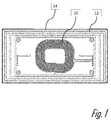
- Fig. 1 shows a non-limiting example of a first transmit coil set 10 and a second transmit coil set 12 formed by conductive traces on a printed circuit board 14 where a first transmit coil set 10 operates at a frequency that is substantially different from a frequency at which a second transmit coil set 12 operates.
- the first transmit coil set 10 is configured to resonate in a first fundamental frequency range and a second transmit coil set 12 is configured to resonate in a second fundamental frequency range.
- the second fundamental frequency range is outside of the first fundamental frequency range and is at least one order of magnitude, i.e., ten times, higher or lower than the first fundamental frequency.
- the first transmit coil set 10 is configured to resonate in a first fundamental frequency range when the Q factor of the first coil set 10 is greater than 0.5 within the first fundamental frequency range.
- the second transmit coil set 12 is configured to resonate in a second fundamental frequency range when the Q factor of the second coil set 12 is greater than 0.5 within the second fundamental frequency range.
- Fig. 1 illustrates an instance in which the first coil set 10 contains one coil structure and the second coil set 12 also contains one coil structure.
- the first coil set and the second coil set may each include one or more coil structures.
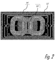
- Fig. 2 illustrates a non-limiting example of a first transmit coil set 10' and a second transmit coil set 12' formed by conductive traces on a printed circuit board 14' where a first transmit coil set 10' operates at a frequency that is substantially different from a frequency at which a second transmit coil set 12' operates.
- the first transmit coil set 10' is configured to resonate in a first fundamental frequency range and a second transmit coil set 12' is configured to resonate in a second fundamental frequency range.
- the second fundamental frequency range is outside of the first fundamental frequency range and is at least one order of magnitude, i.e., ten times, higher or lower than the first fundamental frequency.
- the first coil set 10' in this example includes three coil structures and the second coil set 12' includes one coil structure.
- Fig. 3 shows a non-limiting example of a transmit coil assembly 100 in which the magnetic shielding is shared by the first and second transmit coil sets 10, 12.
- magnetic shielding is provided by a common ferrite shield 102 disposed between the printed circuit board 14 containing the first and second transmit coil sets 10, 12 and a housing 104 formed of a conductive material, such as an aluminum-based, copper-based, or steel-based material, in which the printed circuit board 14 is mounted by threaded fasteners 16.
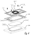
- Fig. 4 shows another non-limiting example of transmit coil assembly 200 with improved magnetic shielding performance.
- the ferrite shield 202 is smaller than the common ferrite shield 102 of the transmit coil assembly 100 shown in Fig. 3 .
- the ferrite shield 202 provides magnetic shielding substantially for only the first transmit coil set 10 by being in close proximity to the first transmit coil set 10 while the distance between the ferrite shield 202 and the second transmit coil set 12 is at least ten time the distance between the ferrite shield 202 and the first transmit coil set 10. This allows for the size and material of the ferrite shield 202 to be selected that is more ideally suited to provide magnetic shielding for the first transmit coil set 10 operating within the first frequency range.
- a spacer 206 is provided for mechanical support of the printed circuit board 14 and the ferrite shield 202.
- the spacer 206 can be made from a dielectric material, such as a plastic material.
- the spacer 206 may be formed of a conductive material, e.g. the same material used to form the ferrite shield 202.
- the material forming the spacer 206 may be selected to optimize magnetic shielding for the second transmit coil set 12 operating in the second frequency range independently of the magnetic shielding of the first transmit coil set 10 operating in the first frequency range.
- a second ferrite shield (not shown) may be placed underneath the spacer 206 intermediate the spacer and the housing 204.
- the printed circuit board 14 and the spacer 206 are secured to the housing 204 by the threaded fasteners 16.
- the housing 204 defines a pedestal 208 beneath the first transmit coil set 10 that creates a small gap (e.g. less than 1 mm) made of material(s) not considered to be a parasitic item, e.g. the ferrite element 202 or air, between a first transmit coil set 10 and the housing 204 and a large gap (e.g. more than 3 mm) made of material(s) not considered to be a parasitic item, e.g. the spacer 206 or air, between a second transmit coil set 12 and the housing 204.
- the spacer 206 defines an aperture 210 extending therethrough in which the pedestal 208 and ferrite element 202 are disposed.
- This transmit coil assembly 200 allows flexibility for choosing different magnetic shielding materials and configurations for independently optimizing magnetic shielding for the first and second transmit coil sets 10, 12 that may improve performance of the wireless power transmitter system.
- the first transmit coil set 10, the second transmit coil set 12, the printed circuit board 14, and the treaded fasteners 16 are common to both the transmit coil assembly 100 and the transmit coil assembly 200.
- the reference numbers of similar elements in the embodiment of the transmit coil assembly 100 shown in Fig. 3 and the embodiment of the transmit coil assembly 200 shown in Fig. 4 differ by 100.
- the magnetic shielding provides an economic solution for combining two or more transmit coils that operate at frequencies substantially different from one another in a single assembly.
- first and second transmit coil sets 10, 12 , 10', 12' in the illustrated examples are formed of conductive traces on a printed circuit board 14, 14', alternative embodiments may be envisioned in which the first and second transmit coils are formed of Litz wire, magnet wire, foil or other suitable conductive elements.
Landscapes
- Engineering & Computer Science (AREA)
- Power Engineering (AREA)
- Computer Networks & Wireless Communication (AREA)
- Physics & Mathematics (AREA)
- Electromagnetism (AREA)
- Shielding Devices Or Components To Electric Or Magnetic Fields (AREA)
- Coils Or Transformers For Communication (AREA)
Applications Claiming Priority (1)
| Application Number | Priority Date | Filing Date | Title |
|---|---|---|---|
| US201562164751P | 2015-05-21 | 2015-05-21 |
Publications (2)
| Publication Number | Publication Date |
|---|---|
| EP3096337A1 true EP3096337A1 (fr) | 2016-11-23 |
| EP3096337B1 EP3096337B1 (fr) | 2021-12-01 |
Family
ID=56026686
Family Applications (1)
| Application Number | Title | Priority Date | Filing Date |
|---|---|---|---|
| EP16170225.3A Active EP3096337B1 (fr) | 2015-05-21 | 2016-05-18 | Émetteur de puissance sans fil à double bobine |
Country Status (3)
| Country | Link |
|---|---|
| US (1) | US10355528B2 (fr) |
| EP (1) | EP3096337B1 (fr) |
| CN (1) | CN106229131B (fr) |
Cited By (3)
| Publication number | Priority date | Publication date | Assignee | Title |
|---|---|---|---|---|
| EP3547496A3 (fr) * | 2018-03-26 | 2020-01-08 | MediaTek Singapore Pte Ltd. | Écosystème et bobines de transfert de puissance sans fil fonctionnant sur des niveaux de puissance sensiblement différents |
| US11351388B1 (en) * | 2018-09-12 | 2022-06-07 | Verily Life Sciences Llc | Wireless power receiver coil for implantable neuromodulation device |
| US11406836B1 (en) | 2018-09-12 | 2022-08-09 | Verily Life Sciences Llc | Wireless power receiver coil for neuromodulation device |
Families Citing this family (11)
| Publication number | Priority date | Publication date | Assignee | Title |
|---|---|---|---|---|
| US9490656B2 (en) | 2013-11-25 | 2016-11-08 | A.K. Stamping Company, Inc. | Method of making a wireless charging coil |
| US9859052B2 (en) | 2013-11-25 | 2018-01-02 | A.K. Stamping Co., Inc. | Wireless charging coil |
| US10855115B2 (en) * | 2015-07-08 | 2020-12-01 | The Regents Of The University Of California | Wireless power transfer device and method with dual-frequency operation |
| KR101804410B1 (ko) | 2015-12-17 | 2017-12-04 | 엘지이노텍 주식회사 | 무선 전력 송신기를 위한 송신 코일 모듈 |
| US20170207664A1 (en) * | 2016-01-19 | 2017-07-20 | Garrity Power Services Llc | Universal wireless power system coil apparatus |
| US11011915B2 (en) | 2016-08-26 | 2021-05-18 | Nucurrent, Inc. | Method of making a wireless connector transmitter module |
| US11605487B2 (en) * | 2017-04-14 | 2023-03-14 | The Diller Corporation | Laminate with induction coils and charging station device comprising same |
| KR102394140B1 (ko) * | 2017-07-03 | 2022-05-09 | 삼성전자 주식회사 | 루프 안테나를 갖는 전자 장치 |
| EP3797435B1 (fr) * | 2018-05-22 | 2023-01-04 | Premo, S.A. | Émetteur/récepteur d'énergie inductive pour chargeur inductif d'un véhicule électrique |
| CN111669926B (zh) | 2020-05-22 | 2021-09-17 | 台达电子企业管理(上海)有限公司 | 电磁场收发装置及无线充电装置 |
| US12230436B2 (en) | 2020-11-25 | 2025-02-18 | International Business Machines Corporation | Spacer to reduce magnetic coupling |
Citations (8)
| Publication number | Priority date | Publication date | Assignee | Title |
|---|---|---|---|---|
| DE102011014752A1 (de) * | 2011-03-09 | 2012-09-13 | Sew-Eurodrive Gmbh & Co. Kg | System zum berührungslosen Übertragen von Energie an ein Fahrzeug |
| US20130075477A1 (en) * | 2010-08-12 | 2013-03-28 | Feinics Amatech Nominee Limited | Coupling in and to rfid smart cards |
| JP2013084915A (ja) * | 2011-10-12 | 2013-05-09 | Tdk Taiwan Corp | 近距離無線通信と無線充電共用の感応モジュール |
| EP2648274A1 (fr) * | 2012-04-05 | 2013-10-09 | LG Electronics, Inc. | Antenne et terminal mobile utilisant l`antenne |
| US20140168019A1 (en) * | 2011-11-02 | 2014-06-19 | Panasonic Corporation | Non-contact wireless communication coil, transmission coil, and portable wireless terminal |
| US20140266030A1 (en) * | 2013-03-12 | 2014-09-18 | Samsung Electro-Mechanics Co., Ltd. | Coil substrate for wireless charging and electric device using the same |
| EP2811614A2 (fr) * | 2013-06-03 | 2014-12-10 | LG Electronics, Inc. | Procédé de transfert de puissance sans fil, émetteur de puissance sans fil et système de charge sans fil |
| US20150130979A1 (en) * | 2013-11-08 | 2015-05-14 | Nokia Corporation | Coil Arrangement |
Family Cites Families (8)
| Publication number | Priority date | Publication date | Assignee | Title |
|---|---|---|---|---|
| JP5058350B1 (ja) * | 2011-03-30 | 2012-10-24 | 株式会社東芝 | 送電装置及び電力伝送システム |
| US9697459B2 (en) * | 2014-08-10 | 2017-07-04 | Féinics Amatech Teoranta | Passive smart cards, metal cards, payment objects and smart jewelry |
| US9726518B2 (en) * | 2012-07-13 | 2017-08-08 | Qualcomm Incorporated | Systems, methods, and apparatus for detection of metal objects in a predetermined space |
| US20140320369A1 (en) * | 2013-04-24 | 2014-10-30 | Broadcom Corporation | Shielding layer for a device having a plurality of antennas |
| US9672976B2 (en) * | 2013-10-28 | 2017-06-06 | Nokia Corporation | Multi-mode wireless charging |
| US9490656B2 (en) * | 2013-11-25 | 2016-11-08 | A.K. Stamping Company, Inc. | Method of making a wireless charging coil |
| US9859052B2 (en) * | 2013-11-25 | 2018-01-02 | A.K. Stamping Co., Inc. | Wireless charging coil |
| WO2015147566A1 (fr) * | 2014-03-27 | 2015-10-01 | 엘지이노텍 주식회사 | Système de transmission d'électricité sans fil ayant un dispositif de transmission d'électricité sans fil |
-
2016
- 2016-05-13 US US15/153,763 patent/US10355528B2/en active Active
- 2016-05-18 EP EP16170225.3A patent/EP3096337B1/fr active Active
- 2016-05-23 CN CN201610629261.9A patent/CN106229131B/zh active Active
Patent Citations (8)
| Publication number | Priority date | Publication date | Assignee | Title |
|---|---|---|---|---|
| US20130075477A1 (en) * | 2010-08-12 | 2013-03-28 | Feinics Amatech Nominee Limited | Coupling in and to rfid smart cards |
| DE102011014752A1 (de) * | 2011-03-09 | 2012-09-13 | Sew-Eurodrive Gmbh & Co. Kg | System zum berührungslosen Übertragen von Energie an ein Fahrzeug |
| JP2013084915A (ja) * | 2011-10-12 | 2013-05-09 | Tdk Taiwan Corp | 近距離無線通信と無線充電共用の感応モジュール |
| US20140168019A1 (en) * | 2011-11-02 | 2014-06-19 | Panasonic Corporation | Non-contact wireless communication coil, transmission coil, and portable wireless terminal |
| EP2648274A1 (fr) * | 2012-04-05 | 2013-10-09 | LG Electronics, Inc. | Antenne et terminal mobile utilisant l`antenne |
| US20140266030A1 (en) * | 2013-03-12 | 2014-09-18 | Samsung Electro-Mechanics Co., Ltd. | Coil substrate for wireless charging and electric device using the same |
| EP2811614A2 (fr) * | 2013-06-03 | 2014-12-10 | LG Electronics, Inc. | Procédé de transfert de puissance sans fil, émetteur de puissance sans fil et système de charge sans fil |
| US20150130979A1 (en) * | 2013-11-08 | 2015-05-14 | Nokia Corporation | Coil Arrangement |
Cited By (8)
| Publication number | Priority date | Publication date | Assignee | Title |
|---|---|---|---|---|
| EP3547496A3 (fr) * | 2018-03-26 | 2020-01-08 | MediaTek Singapore Pte Ltd. | Écosystème et bobines de transfert de puissance sans fil fonctionnant sur des niveaux de puissance sensiblement différents |
| TWI710195B (zh) * | 2018-03-26 | 2020-11-11 | 新加坡商 聯發科技(新加坡)私人有限公司 | 無線電力發射器/接收器裝置 |
| US10916971B2 (en) | 2018-03-26 | 2021-02-09 | Mediatek Singapore Pte. Ltd. | Wireless power transfer ecosystem and coils operating on substantially different power levels |
| EP4622062A3 (fr) * | 2018-03-26 | 2025-12-24 | MediaTek Singapore Pte Ltd | Écosystème et bobines de transfert de puissance sans fil fonctionnant sur des niveaux de puissance sensiblement différents |
| US11351388B1 (en) * | 2018-09-12 | 2022-06-07 | Verily Life Sciences Llc | Wireless power receiver coil for implantable neuromodulation device |
| US11406836B1 (en) | 2018-09-12 | 2022-08-09 | Verily Life Sciences Llc | Wireless power receiver coil for neuromodulation device |
| US11857797B1 (en) | 2018-09-12 | 2024-01-02 | Verily Life Sciences Llc | Wireless power receiver coil for implantable neuromodulation device |
| US12102834B2 (en) | 2018-09-12 | 2024-10-01 | Verily Life Sciences Llc | Wireless power receiver coil for neuromodulation device |
Also Published As
| Publication number | Publication date |
|---|---|
| US20170033610A1 (en) | 2017-02-02 |
| US10355528B2 (en) | 2019-07-16 |
| CN106229131A (zh) | 2016-12-14 |
| CN106229131B (zh) | 2019-12-10 |
| EP3096337B1 (fr) | 2021-12-01 |
Similar Documents
| Publication | Publication Date | Title |
|---|---|---|
| US10355528B2 (en) | Dual coil wireless power transmitter | |
| EP3370240A1 (fr) | Transformateur | |
| WO2014004282A1 (fr) | Intégration d'antenne de communication en champ proche (nfc) à châssis étroit | |
| KR101646492B1 (ko) | 무선 충전 모듈 및 차폐시트 | |
| JP2013055637A (ja) | アンテナ装置および通信端末装置 | |
| GB2540118A (en) | Communication terminal device | |
| JPWO2015137430A1 (ja) | ワイヤレス給電装置 | |
| JP5891359B2 (ja) | 複共振型アンテナ装置 | |
| CN110998764B (zh) | 无线电力收发器和具有其的显示装置 | |
| JP6232191B2 (ja) | 給電部、受電部及び給電システム | |
| JP2019041529A (ja) | 無線電力伝送システム | |
| JPWO2016143724A1 (ja) | 通信端末装置 | |
| US20170207664A1 (en) | Universal wireless power system coil apparatus | |
| US9660329B2 (en) | Directional antenna | |
| US20220224004A1 (en) | Antenna unit and communication equipment | |
| US10020571B2 (en) | Antenna mounting system for metallic structures | |
| EP3669389B1 (fr) | Topologie d'un blindage en ferrite pour bobines inductives | |
| EP4258301B1 (fr) | Enceinte | |
| US7221163B2 (en) | Magnetic resonance system with suppression of capacitive coupling between an RF source and the subject | |
| US20210152020A1 (en) | Power reception device | |
| JP2017216788A (ja) | 無線装置 | |
| JP6693293B2 (ja) | ワイヤレス受電装置、及びこれを用いた電子機器 | |
| JP7689974B2 (ja) | 高固有品質受信機構造 | |
| US10243413B2 (en) | Resonance type power transmission device | |
| CN104241848B (zh) | 无线通信装置 |
Legal Events
| Date | Code | Title | Description |
|---|---|---|---|
| PUAI | Public reference made under article 153(3) epc to a published international application that has entered the european phase |
Free format text: ORIGINAL CODE: 0009012 |
|
| AK | Designated contracting states |
Kind code of ref document: A1 Designated state(s): AL AT BE BG CH CY CZ DE DK EE ES FI FR GB GR HR HU IE IS IT LI LT LU LV MC MK MT NL NO PL PT RO RS SE SI SK SM TR |
|
| AX | Request for extension of the european patent |
Extension state: BA ME |
|
| STAA | Information on the status of an ep patent application or granted ep patent |
Free format text: STATUS: REQUEST FOR EXAMINATION WAS MADE |
|
| 17P | Request for examination filed |
Effective date: 20170523 |
|
| RBV | Designated contracting states (corrected) |
Designated state(s): AL AT BE BG CH CY CZ DE DK EE ES FI FR GB GR HR HU IE IS IT LI LT LU LV MC MK MT NL NO PL PT RO RS SE SI SK SM TR |
|
| RAP1 | Party data changed (applicant data changed or rights of an application transferred) |
Owner name: APTIV TECHNOLOGIES LIMITED |
|
| STAA | Information on the status of an ep patent application or granted ep patent |
Free format text: STATUS: EXAMINATION IS IN PROGRESS |
|
| 17Q | First examination report despatched |
Effective date: 20210323 |
|
| REG | Reference to a national code |
Ref country code: DE Ref legal event code: R079 Ref document number: 602016066736 Country of ref document: DE Free format text: PREVIOUS MAIN CLASS: H01F0027360000 Ipc: H02J0050120000 |
|
| GRAP | Despatch of communication of intention to grant a patent |
Free format text: ORIGINAL CODE: EPIDOSNIGR1 |
|
| STAA | Information on the status of an ep patent application or granted ep patent |
Free format text: STATUS: GRANT OF PATENT IS INTENDED |
|
| RIC1 | Information provided on ipc code assigned before grant |
Ipc: H02J 50/12 20160101AFI20210430BHEP Ipc: H02J 50/70 20160101ALI20210430BHEP Ipc: H02J 50/40 20160101ALI20210430BHEP Ipc: H01F 38/14 20060101ALI20210430BHEP Ipc: H01F 27/36 20060101ALI20210430BHEP |
|
| GRAJ | Information related to disapproval of communication of intention to grant by the applicant or resumption of examination proceedings by the epo deleted |
Free format text: ORIGINAL CODE: EPIDOSDIGR1 |
|
| STAA | Information on the status of an ep patent application or granted ep patent |
Free format text: STATUS: EXAMINATION IS IN PROGRESS |
|
| GRAS | Grant fee paid |
Free format text: ORIGINAL CODE: EPIDOSNIGR3 |
|
| STAA | Information on the status of an ep patent application or granted ep patent |
Free format text: STATUS: GRANT OF PATENT IS INTENDED |
|
| INTG | Intention to grant announced |
Effective date: 20210527 |
|
| GRAP | Despatch of communication of intention to grant a patent |
Free format text: ORIGINAL CODE: EPIDOSNIGR1 |
|
| INTC | Intention to grant announced (deleted) | ||
| INTG | Intention to grant announced |
Effective date: 20210629 |
|
| GRAA | (expected) grant |
Free format text: ORIGINAL CODE: 0009210 |
|
| STAA | Information on the status of an ep patent application or granted ep patent |
Free format text: STATUS: THE PATENT HAS BEEN GRANTED |
|
| AK | Designated contracting states |
Kind code of ref document: B1 Designated state(s): AL AT BE BG CH CY CZ DE DK EE ES FI FR GB GR HR HU IE IS IT LI LT LU LV MC MK MT NL NO PL PT RO RS SE SI SK SM TR |
|
| REG | Reference to a national code |
Ref country code: GB Ref legal event code: FG4D |
|
| REG | Reference to a national code |
Ref country code: AT Ref legal event code: REF Ref document number: 1452713 Country of ref document: AT Kind code of ref document: T Effective date: 20211215 Ref country code: CH Ref legal event code: EP |
|
| REG | Reference to a national code |
Ref country code: IE Ref legal event code: FG4D |
|
| REG | Reference to a national code |
Ref country code: DE Ref legal event code: R096 Ref document number: 602016066736 Country of ref document: DE |
|
| REG | Reference to a national code |
Ref country code: LT Ref legal event code: MG9D |
|
| REG | Reference to a national code |
Ref country code: NL Ref legal event code: MP Effective date: 20211201 |
|
| REG | Reference to a national code |
Ref country code: AT Ref legal event code: MK05 Ref document number: 1452713 Country of ref document: AT Kind code of ref document: T Effective date: 20211201 |
|
| PG25 | Lapsed in a contracting state [announced via postgrant information from national office to epo] |
Ref country code: RS Free format text: LAPSE BECAUSE OF FAILURE TO SUBMIT A TRANSLATION OF THE DESCRIPTION OR TO PAY THE FEE WITHIN THE PRESCRIBED TIME-LIMIT Effective date: 20211201 Ref country code: LT Free format text: LAPSE BECAUSE OF FAILURE TO SUBMIT A TRANSLATION OF THE DESCRIPTION OR TO PAY THE FEE WITHIN THE PRESCRIBED TIME-LIMIT Effective date: 20211201 Ref country code: FI Free format text: LAPSE BECAUSE OF FAILURE TO SUBMIT A TRANSLATION OF THE DESCRIPTION OR TO PAY THE FEE WITHIN THE PRESCRIBED TIME-LIMIT Effective date: 20211201 Ref country code: BG Free format text: LAPSE BECAUSE OF FAILURE TO SUBMIT A TRANSLATION OF THE DESCRIPTION OR TO PAY THE FEE WITHIN THE PRESCRIBED TIME-LIMIT Effective date: 20220301 Ref country code: AT Free format text: LAPSE BECAUSE OF FAILURE TO SUBMIT A TRANSLATION OF THE DESCRIPTION OR TO PAY THE FEE WITHIN THE PRESCRIBED TIME-LIMIT Effective date: 20211201 |
|
| PG25 | Lapsed in a contracting state [announced via postgrant information from national office to epo] |
Ref country code: SE Free format text: LAPSE BECAUSE OF FAILURE TO SUBMIT A TRANSLATION OF THE DESCRIPTION OR TO PAY THE FEE WITHIN THE PRESCRIBED TIME-LIMIT Effective date: 20211201 Ref country code: PL Free format text: LAPSE BECAUSE OF FAILURE TO SUBMIT A TRANSLATION OF THE DESCRIPTION OR TO PAY THE FEE WITHIN THE PRESCRIBED TIME-LIMIT Effective date: 20211201 Ref country code: NO Free format text: LAPSE BECAUSE OF FAILURE TO SUBMIT A TRANSLATION OF THE DESCRIPTION OR TO PAY THE FEE WITHIN THE PRESCRIBED TIME-LIMIT Effective date: 20220301 Ref country code: LV Free format text: LAPSE BECAUSE OF FAILURE TO SUBMIT A TRANSLATION OF THE DESCRIPTION OR TO PAY THE FEE WITHIN THE PRESCRIBED TIME-LIMIT Effective date: 20211201 Ref country code: HR Free format text: LAPSE BECAUSE OF FAILURE TO SUBMIT A TRANSLATION OF THE DESCRIPTION OR TO PAY THE FEE WITHIN THE PRESCRIBED TIME-LIMIT Effective date: 20211201 Ref country code: GR Free format text: LAPSE BECAUSE OF FAILURE TO SUBMIT A TRANSLATION OF THE DESCRIPTION OR TO PAY THE FEE WITHIN THE PRESCRIBED TIME-LIMIT Effective date: 20220302 Ref country code: ES Free format text: LAPSE BECAUSE OF FAILURE TO SUBMIT A TRANSLATION OF THE DESCRIPTION OR TO PAY THE FEE WITHIN THE PRESCRIBED TIME-LIMIT Effective date: 20211201 |
|
| PG25 | Lapsed in a contracting state [announced via postgrant information from national office to epo] |
Ref country code: NL Free format text: LAPSE BECAUSE OF FAILURE TO SUBMIT A TRANSLATION OF THE DESCRIPTION OR TO PAY THE FEE WITHIN THE PRESCRIBED TIME-LIMIT Effective date: 20211201 |
|
| PG25 | Lapsed in a contracting state [announced via postgrant information from national office to epo] |
Ref country code: SM Free format text: LAPSE BECAUSE OF FAILURE TO SUBMIT A TRANSLATION OF THE DESCRIPTION OR TO PAY THE FEE WITHIN THE PRESCRIBED TIME-LIMIT Effective date: 20211201 Ref country code: SK Free format text: LAPSE BECAUSE OF FAILURE TO SUBMIT A TRANSLATION OF THE DESCRIPTION OR TO PAY THE FEE WITHIN THE PRESCRIBED TIME-LIMIT Effective date: 20211201 Ref country code: RO Free format text: LAPSE BECAUSE OF FAILURE TO SUBMIT A TRANSLATION OF THE DESCRIPTION OR TO PAY THE FEE WITHIN THE PRESCRIBED TIME-LIMIT Effective date: 20211201 Ref country code: PT Free format text: LAPSE BECAUSE OF FAILURE TO SUBMIT A TRANSLATION OF THE DESCRIPTION OR TO PAY THE FEE WITHIN THE PRESCRIBED TIME-LIMIT Effective date: 20220401 Ref country code: EE Free format text: LAPSE BECAUSE OF FAILURE TO SUBMIT A TRANSLATION OF THE DESCRIPTION OR TO PAY THE FEE WITHIN THE PRESCRIBED TIME-LIMIT Effective date: 20211201 Ref country code: CZ Free format text: LAPSE BECAUSE OF FAILURE TO SUBMIT A TRANSLATION OF THE DESCRIPTION OR TO PAY THE FEE WITHIN THE PRESCRIBED TIME-LIMIT Effective date: 20211201 |
|
| REG | Reference to a national code |
Ref country code: DE Ref legal event code: R097 Ref document number: 602016066736 Country of ref document: DE |
|
| PG25 | Lapsed in a contracting state [announced via postgrant information from national office to epo] |
Ref country code: IS Free format text: LAPSE BECAUSE OF FAILURE TO SUBMIT A TRANSLATION OF THE DESCRIPTION OR TO PAY THE FEE WITHIN THE PRESCRIBED TIME-LIMIT Effective date: 20220401 |
|
| PLBE | No opposition filed within time limit |
Free format text: ORIGINAL CODE: 0009261 |
|
| STAA | Information on the status of an ep patent application or granted ep patent |
Free format text: STATUS: NO OPPOSITION FILED WITHIN TIME LIMIT |
|
| PG25 | Lapsed in a contracting state [announced via postgrant information from national office to epo] |
Ref country code: DK Free format text: LAPSE BECAUSE OF FAILURE TO SUBMIT A TRANSLATION OF THE DESCRIPTION OR TO PAY THE FEE WITHIN THE PRESCRIBED TIME-LIMIT Effective date: 20211201 Ref country code: AL Free format text: LAPSE BECAUSE OF FAILURE TO SUBMIT A TRANSLATION OF THE DESCRIPTION OR TO PAY THE FEE WITHIN THE PRESCRIBED TIME-LIMIT Effective date: 20211201 |
|
| 26N | No opposition filed |
Effective date: 20220902 |
|
| PG25 | Lapsed in a contracting state [announced via postgrant information from national office to epo] |
Ref country code: SI Free format text: LAPSE BECAUSE OF FAILURE TO SUBMIT A TRANSLATION OF THE DESCRIPTION OR TO PAY THE FEE WITHIN THE PRESCRIBED TIME-LIMIT Effective date: 20211201 |
|
| REG | Reference to a national code |
Ref country code: CH Ref legal event code: PL |
|
| REG | Reference to a national code |
Ref country code: BE Ref legal event code: MM Effective date: 20220531 |
|
| PG25 | Lapsed in a contracting state [announced via postgrant information from national office to epo] |
Ref country code: MC Free format text: LAPSE BECAUSE OF FAILURE TO SUBMIT A TRANSLATION OF THE DESCRIPTION OR TO PAY THE FEE WITHIN THE PRESCRIBED TIME-LIMIT Effective date: 20211201 Ref country code: LU Free format text: LAPSE BECAUSE OF NON-PAYMENT OF DUE FEES Effective date: 20220518 Ref country code: LI Free format text: LAPSE BECAUSE OF NON-PAYMENT OF DUE FEES Effective date: 20220531 Ref country code: CH Free format text: LAPSE BECAUSE OF NON-PAYMENT OF DUE FEES Effective date: 20220531 |
|
| PG25 | Lapsed in a contracting state [announced via postgrant information from national office to epo] |
Ref country code: IE Free format text: LAPSE BECAUSE OF NON-PAYMENT OF DUE FEES Effective date: 20220518 |
|
| PG25 | Lapsed in a contracting state [announced via postgrant information from national office to epo] |
Ref country code: IT Free format text: LAPSE BECAUSE OF FAILURE TO SUBMIT A TRANSLATION OF THE DESCRIPTION OR TO PAY THE FEE WITHIN THE PRESCRIBED TIME-LIMIT Effective date: 20211201 Ref country code: BE Free format text: LAPSE BECAUSE OF NON-PAYMENT OF DUE FEES Effective date: 20220531 |
|
| P01 | Opt-out of the competence of the unified patent court (upc) registered |
Effective date: 20230424 |
|
| PG25 | Lapsed in a contracting state [announced via postgrant information from national office to epo] |
Ref country code: HU Free format text: LAPSE BECAUSE OF FAILURE TO SUBMIT A TRANSLATION OF THE DESCRIPTION OR TO PAY THE FEE WITHIN THE PRESCRIBED TIME-LIMIT; INVALID AB INITIO Effective date: 20160518 |
|
| PG25 | Lapsed in a contracting state [announced via postgrant information from national office to epo] |
Ref country code: MK Free format text: LAPSE BECAUSE OF FAILURE TO SUBMIT A TRANSLATION OF THE DESCRIPTION OR TO PAY THE FEE WITHIN THE PRESCRIBED TIME-LIMIT Effective date: 20211201 Ref country code: CY Free format text: LAPSE BECAUSE OF FAILURE TO SUBMIT A TRANSLATION OF THE DESCRIPTION OR TO PAY THE FEE WITHIN THE PRESCRIBED TIME-LIMIT Effective date: 20211201 |
|
| PG25 | Lapsed in a contracting state [announced via postgrant information from national office to epo] |
Ref country code: TR Free format text: LAPSE BECAUSE OF FAILURE TO SUBMIT A TRANSLATION OF THE DESCRIPTION OR TO PAY THE FEE WITHIN THE PRESCRIBED TIME-LIMIT Effective date: 20211201 |
|
| PG25 | Lapsed in a contracting state [announced via postgrant information from national office to epo] |
Ref country code: MT Free format text: LAPSE BECAUSE OF FAILURE TO SUBMIT A TRANSLATION OF THE DESCRIPTION OR TO PAY THE FEE WITHIN THE PRESCRIBED TIME-LIMIT Effective date: 20211201 |
|
| REG | Reference to a national code |
Ref country code: DE Ref legal event code: R081 Ref document number: 602016066736 Country of ref document: DE Owner name: APTIV TECHNOLOGIES AG, CH Free format text: FORMER OWNER: APTIV TECHNOLOGIES LIMITED, ST. MICHAEL, BB |
|
| PGFP | Annual fee paid to national office [announced via postgrant information from national office to epo] |
Ref country code: DE Payment date: 20250422 Year of fee payment: 10 |
|
| PGFP | Annual fee paid to national office [announced via postgrant information from national office to epo] |
Ref country code: FR Payment date: 20250513 Year of fee payment: 10 |
|
| PGFP | Annual fee paid to national office [announced via postgrant information from national office to epo] |
Ref country code: GB Payment date: 20260313 Year of fee payment: 11 |