EP3096340B1 - Système d'arrêt électromagnétique de type à clapet - Google Patents
Système d'arrêt électromagnétique de type à clapet Download PDFInfo
- Publication number
- EP3096340B1 EP3096340B1 EP15737547.8A EP15737547A EP3096340B1 EP 3096340 B1 EP3096340 B1 EP 3096340B1 EP 15737547 A EP15737547 A EP 15737547A EP 3096340 B1 EP3096340 B1 EP 3096340B1
- Authority
- EP
- European Patent Office
- Prior art keywords
- iron core
- armature
- wire
- type electromagnetic
- bracket
- Prior art date
- Legal status (The legal status is an assumption and is not a legal conclusion. Google has not performed a legal analysis and makes no representation as to the accuracy of the status listed.)
- Active
Links
Images


Classifications
-
- H—ELECTRICITY
- H01—ELECTRIC ELEMENTS
- H01H—ELECTRIC SWITCHES; RELAYS; SELECTORS; EMERGENCY PROTECTIVE DEVICES
- H01H71/00—Details of the protective switches or relays covered by groups H01H73/00 - H01H83/00
- H01H71/10—Operating or release mechanisms
- H01H71/12—Automatic release mechanisms with or without manual release
- H01H71/40—Combined electrothermal and electromagnetic mechanisms
-
- H—ELECTRICITY
- H01—ELECTRIC ELEMENTS
- H01H—ELECTRIC SWITCHES; RELAYS; SELECTORS; EMERGENCY PROTECTIVE DEVICES
- H01H71/00—Details of the protective switches or relays covered by groups H01H73/00 - H01H83/00
- H01H71/10—Operating or release mechanisms
- H01H71/12—Automatic release mechanisms with or without manual release
- H01H71/14—Electrothermal mechanisms
- H01H71/16—Electrothermal mechanisms with bimetal element
- H01H71/164—Heating elements
-
- H—ELECTRICITY
- H01—ELECTRIC ELEMENTS
- H01H—ELECTRIC SWITCHES; RELAYS; SELECTORS; EMERGENCY PROTECTIVE DEVICES
- H01H71/00—Details of the protective switches or relays covered by groups H01H73/00 - H01H83/00
- H01H71/10—Operating or release mechanisms
- H01H71/12—Automatic release mechanisms with or without manual release
- H01H71/24—Electromagnetic mechanisms
- H01H71/2472—Electromagnetic mechanisms with rotatable armatures
-
- H—ELECTRICITY
- H01—ELECTRIC ELEMENTS
- H01H—ELECTRIC SWITCHES; RELAYS; SELECTORS; EMERGENCY PROTECTIVE DEVICES
- H01H71/00—Details of the protective switches or relays covered by groups H01H73/00 - H01H83/00
- H01H71/10—Operating or release mechanisms
- H01H71/12—Automatic release mechanisms with or without manual release
- H01H71/40—Combined electrothermal and electromagnetic mechanisms
- H01H71/402—Combined electrothermal and electromagnetic mechanisms in which the thermal mechanism influences the magnetic circuit of the electromagnetic mechanism
-
- H—ELECTRICITY
- H01—ELECTRIC ELEMENTS
- H01H—ELECTRIC SWITCHES; RELAYS; SELECTORS; EMERGENCY PROTECTIVE DEVICES
- H01H71/00—Details of the protective switches or relays covered by groups H01H73/00 - H01H83/00
- H01H71/10—Operating or release mechanisms
- H01H71/12—Automatic release mechanisms with or without manual release
- H01H71/40—Combined electrothermal and electromagnetic mechanisms
- H01H2071/407—Combined electrothermal and electromagnetic mechanisms the thermal element being heated by the coil of the electromagnetic mechanism
Definitions
- the present invention-creation belongs to the technical field of molded case circuit breakers, and more particularly relates to a clapping type electromagnetic tripping system of a molded case circuit breaker.
- a clapping type electromagnetic tripping system of a molded case circuit breaker in which an electromagnetic field is generated on an iron core using a short-circuited current flowing through a heating element and an armature is attracted to push a tripping rod to make a product disconnected ensures the safety of a power supply system; and this clapping type electromagnetic tripping system mainly comprises an iron core, an armature, a heating element, a thermal bimetallic element, a bracket, a supporting member, a flexible wire and a connecting plate.
- the heating element penetrates through a magnetic loop composed of the armature and the iron core, and a magnetic field will be generated on the iron core surrounding the heating element when the short-circuited current flows through the heating element; and if the generated magnetic field force is not sufficient to attract the armature, short-circuit protection fails, and in particular, in a clapping type electromagnetic tripping system of a specification of 63A or less.
- EP0143022 A1 discloses a clapping type electromagnetic tripping system according to the preamble of claim 1.
- the present invention-creation aims to overcoming the defects of the prior art and provide a clapping type electromagnetic system which is simple in structure and high in reliability.
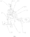
- a clapping type electromagnetic tripping system comprises an iron core 107 with a U-shaped structure, an armature 101, a heating element 103, a bimetallic element 102 and a connecting plate 106, wherein a bracket 104 extends into a U-shaped groove of the iron core 107 and is fixedly connected with the iron core 107, and a wire 105 connecting the heating element 103 and the connecting plate 106 surrounds the iron core 107 and the bracket 104 at least one lap; the bracket 104 which surrounded by at least one lap of the wire 105, is fixedly connected with the middle part of the heating element 103, the bottom end of the heating element 103 and the bottom end of the bimetallic element 102 are fixedly connected with a supporting member 108 together, and the armature 101 is hung on the bracket 104 which is surrounded by at least one lap of the wire 105; and the armature 101 and the iron core 107 surrounded by at least one
- the armature 101 comprises a sheet attracting portion 1011, a first hanging pillar 1013 and a second hanging pillar 1014 which are connected with the attracting portion 1011, and bending portions 1012 which are arranged at positions where the attracting portion 1011 is connected with the first hanging pillar 1013 and the second hanging pillar 1014, and extend towards the iron core 107; and a pair of projections 1015 which are in mounting fit to the bracket 104 are disposed on the first hanging pillar 1013 and the second hanging pillar 1014, and a propping portion 1016 which is used for triggering a tripping action and is bent in a direction away from the iron core 107 is disposed at the end portion of the first hanging pillar 1013.
- the iron core 107 is of a U-shaped structure composed of two sides 1071 and a bottom surface 1072, the two sides 1071 are uniform in shape and symmetrically arranged, and a bevel edge 1073 which can increase a swing range of the armature 101 along a movement direction of the armature 101 which is being attracted is disposed on each of the two sides.
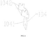
- the bracket 104 comprises a sheet assisting portion 1041 which extends into the U-shaped groove of the iron core 107 and is fixedly connected with a bottom surface 1072 of the iron core 107, a pair of armature supporting arms 1042 which extend towards the armature 101 are disposed at the upper end of the assisting portion 1041 which is fixedly connected with the bottom surface 1072 of the iron core 107, and each of the pair of armature supporting arms 1042 is provided with a groove which is mounting fit to the iron core 107.
- the middle part of the bottom end of the attracting portion 1011 of the armature 101 is recessed, and a pair of bottom legs 1017 are disposed at two sides of the attracting portion 1011.
- the iron core 107 is disposed opposite to the attracting portion 1011 of the armature 101, and a width W2 of the core iron 107 is equal to a width W1 of the attracting portion 1011 of the armature 1011.
- a height H2 of the iron core 107 is equal to a height H1 of the attracting portion 1011 of the armature 101
- the supporting member 108 comprises a supporting member connecting sheet 1082 which is disposed under a recess in the middle part of the bottom end of the armature 101, and a connecting member fixing portion 1081 which is fixedly connected with the bottom end of a bimetallic sheet, and the conjunction between the supporting member fixing portion 1081 and the supporting member connecting sheet 1082 is of a vertical structure.
- a second wire 109 which does not surround the bracket 104 and the heating element 103 with lap(s), and the second wire 109 is connected to the wire 105 in parallel, and is also connected between the heating element 103 and the connecting plate 106
- the wire 105 which surrounds the iron core 107 and the bracket 104 at least one lap is an enameled wire or a flexible connecting wire.
- the clapping type electromagnetic tripping system disclosed by the present invention-creation is simple and reasonable in structure and can enable the armature to be attracted reliably.
- the clapping type electromagnetic tripping system is suitable for use in a low-current molded case circuit breaker with a clapping type electromagnetic structure, and in particular in a clapping type electromagnetic tripping system of a specification of 63A or less.
- a clapping type electromagnetic tripping system of the present invention-creation comprises an iron core 107 with a U-shaped structure, a bracket 104, an armature 101, a heating element 103, a bimetallic element 102, a wire 105, a supporting member 108 and a connecting plate 106.
- the bracket 104 extends into a U-shaped groove of the iron core 107 and is fixedly connected with the iron core 107, a pair of grooves in which the armature 101 is mounted are formed in two sides of the upper end of the bracket 104, and the wire 105 connecting the heating element 103 and the connecting plate 106 surrounds the iron core 107 and the bracket 104 with at least one lap.
- the bracket 104 surrounded by at least one lap of the wire 105, and bracket 104 is fixedly connected with the middle part of the heating element 103, and the bottom end of the heating element 103 and the bottom end of the bimetallic element 102 are fixedly connected with the supporting member 108 together; a pair of projections 1015 which are matched with a pair of grooves in the bracket 104 are disposed on corresponding positions on two sides of the armature 101, and the armature 101 is hung on the bracket 104 through the pair of projections 1015; and the armature 101 and the iron core 107 are arranged oppositely to form a magnetic loop, and one end of the armature 101 is attracted towards the iron core 107 so as to swing during short-circuiting.
- the clapping type electromagnetic tripping system disclosed by the present invention-creation is simple and reasonable in structure , can enable the armature to be attracted reliably and is suitable for use in a low-current molded case circuit breaker with a clapping type electromagnetic structure, and in particular in a clapping type electromagnetic tripping system of a specification of 63A or less.
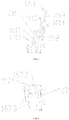
- FIG. 3 is a structural view of another embodiment of the clapping type electromagnetic system of the present invention-creation, and the embodiment as shown in FIG. 3 differs from the embodiment as shown in FIG. 1 in that: a second wire 109 which is connected with the wire 105 in parallel and does not surround the bracket 104 and the heating element 103 with any lap, and the second wire 109 is also connected between the heating element 103 and the connecting plate 106, and sectional areas of the wire 105 and the second wire 109 are reasonably allocated to ensure sufficient magnetic field force generated from current flowing through the wire 105.
- the structure of the armature of the present invention-creation is as shown in FIG. 4 .
- the armature 101 comprises a sheet attracting portion 1011, a first hanging pillar 1013 and a second hanging pillar 1014 which are connected with the attracting portion 1011, and bending portions 1012 which are arranged at positions where the attracting portion 1011 is connected with the first hanging pillar 1013 and the second hanging pillar 1014, and extend towards the iron core 107, wherein the bending portions 1012 can increase a swing range of the armature effectively.
- a pair of projections 1015 which are in mounting fit to a pair of grooves of the bracket 104 are disposed on the first hanging pillar 1013 and second hanging pillar 1014, and a propping portion 1016 which is used for triggering a tripping action is disposed at the end portion of the first hanging pillar 1013 and is bent toward a direction away from the iron core 107 such that the reliability of triggering the tripping action is improved.
- the middle part of the bottom end of the attracting portion 1011 is recessed, a pair of bottom legs 1017 are disposed at two sides of the attracting portion 1011, the supporting member 108 is disposed under a recess of the middle part of the bottom end of the attracting portion 1011 to facilitate reduction of a volume of the electromagnetic tripping system, and the recess in the middle part of the bottom end of the attracting portion 1011 facilitates reduction of the weight of the armature; and a pair of bottom legs 1017 at two sides of the bottom end of the attracting portion 1011 are also very important, and the pair of bottom legs 1017 and two sides 1071 of the iron core 107 are arranged oppositely such that a suction force generated by a magnetic loop can be sufficiently utilized.
- the structure of the supporting member 108 under the recess in the middle part of the bottom end of the attracting portion 1011 is as shown in FIG. 2 , and the supporting member 108 comprises a supporting member connecting sheet 1082 disposed under the recess in the middle part of the bottom end of the armature 101, and a supporting member fixing portion 1081 which is fixedly connected with the bottom end of the bimetallic sheet, wherein the conjunction between the supporting member fixing portion 1081 and the supporting member connecting sheet 1082 is of a vertical structure.
- the structure of the iron core of the present invention-creation is as shown in FIG. 5 .
- the iron core 107 is of a U-shaped structure composed of two sides 1071 and a bottom surface 1072, wherein the two sides 1071 are uniform in shape and disposed symmetrically, and a bevel edge 1073 which can increase a swing range of the armature 101 along a movement direction of the armature 101 which is being attracted is disposed on each of the two sides.
- the iron core 107 and the attracting portion 1011 of the armature 101 are arranged oppositely such that the suction force generated by the magnetic loop can be utilized reasonably to ensure the reliability of triggering a tripping action.
- a width W2 of the iron core 107 is equal to a width W1 of the attracting portion 1011.
- a height H2 of the iron core 107 is equal to a height H1 of the attracting portion 1011, and the uniform heights are just a further preferred embodiment.
- the bracket 104 comprises a sheet assisting portion 1041 which extends into the U-shaped groove of the iron core 107 and is fixedly connected with a bottom surface 1072 of the iron core 107, and the assisting portion 1041 can increase the thickness of the iron core effectively; and a pair of armature supporting arms 1042 which extend toward the armature 101 are disposed at the upper end of the assisting portion 1041 which is fixedly connected with the bottom surface 1072 of the iron core 107 and can increase a swing range of the armature, and each of the armature supporting arms 1042 is provided with a groove which is mounting fit to the iron core 107.
- a current flowing through a magnetic loop composed of the armature 101 and the iron core 107 increases sharply during short-circuiting to break a balance of the electromagnetic tripping system; the attracting portion 1011 of the armature 101 is attracted toward the iron core 107, and the armature 101 swings around a pair of grooves of the bracket 104; and a propping portion 1016 moves along a direction away from the iron core 107 to trigger tripping of the current breaker to realize protection to a load.
- each of the iron core 107, the bracket 104 and the heating element 103 is provided with a connecting hole, and the connecting holes can be riveted once together.
- the bottom end of the heating element 103 and the bottom end of the bimetallic element 102 are fixedly connected with the supporting member 108 through welding.
- the wire 105 which surrounds the iron core 107 and the bracket 104 with at least one lap, is an enameled wire or a flexible connecting wire.
- the present invention-creation is not limited to above-mentioned technical solutions.
Landscapes
- Physics & Mathematics (AREA)
- Electromagnetism (AREA)
- Breakers (AREA)
- General Induction Heating (AREA)
Claims (10)
- Un système d'arrêt électromagnétique du type à clapet, comprenant un noyau en fer (107) ayant une structure en forme de U, une armature (101), un élément de chauffage (103), un élément bimétallique (102) et une plaque de connexion (106), dans lequel un support de fixation (104) s'étend dans une rainure en forme de U du noyau de fer (107) et est connectée de manière fixe au noyau de fer (107), et à un câble (105) connectant l'élément de chauffage (103) à la plaque de connexion (106), caractérisé en ce que le câble (105) entoure le noyau de fer (107) et le support de fixation (104) avec au moins enroulement ; le support de fixation (104) entourée par au moins un enroulement du câble (105) est connectée de manière fixe à la partie centrale de l'élément de chauffage (103), l'extrémité inférieure de l'élément de chauffage (103) et l'extrémité inférieure de l'élément bimétallique (102) sont connectés de manière fixe ensemble avec un organe de support (108), et l'armature (101) est suspendue au support de fixation (104) qui est entourée par au moins un enroulement du câble (105) ; et l'armature (101) et le noyau de fer (107) entouré par au moins un enroulement du câble (105) sont agencés face à face pour former une boucle magnétique, et une extrémité de l'armature (101) est attirée par le noyau de fer (107) de manière à osciller lorsqu'un courant de court-circuit est généré.
- Le système d'arrêt électromagnétique à clapet selon la revendication 1, dans lequel l'armature (101) comprend une partie d'attraction de feuille (1011), une première tige de suspension (1013) et une seconde tige de suspension (1014) qui sont connectées à la partie d'attraction (1011), et des parties de courbure (1012) qui sont agencées à des endroits où la partie d'attraction (1011) est connectée avec la première tige de suspension (1013) et la seconde tige de suspension (1014), et s'étend vers le noyau de fer (107) ; et une paire de protubérances (1015) qui sont ajustées pour un montage sur le support de fixation (104) sont disposées sur la première tige de suspension (1013) et la seconde tige de suspension (1014), et une partie de soutènement (1016) qui est utilisée pour déclencher une action d'arrêt et est courbée dans une direction s'éloignant du noyau de fer (107) est disposée au niveau de la partie d'extrémité du premier pilier de suspension (1013).
- Le système d'arrêt électromagnétique du type à clapet selon la revendication 1, dans lequel, le noyau de fer (107) est constitué d'une structure en forme de U composée de deux côtés (1071) et d'une surface inférieure (1072), les deux côtés (1071) sont identiques en forme et disposés symétriquement, et un bord biseauté (1073) qui peut augmenter une amplitude d'oscillation de l'armature (101) le long d'une direction de déplacement de l'armature (101) qui est en train d'être attirée, est disposé sur chacun des deux côtés.
- Le système d'arrêt électromagnétique du type à clapet selon la revendication 1, dans lequel le support de fixation (104) comprend une partie complémentaire en forme de feuille (1041) qui s'étend dans la rainure en forme de U du noyau de fer (107) et est connectée de manière fixe à une surface inférieure (1072) du noyau de fer (107), une paire de bras de support d'armature (1042) qui s'étendent vers l'armature (101) est disposée à l'extrémité supérieure de la partie complémentaire (1041) qui est connectée de manière fixe à la surface inférieure (1072) du noyau de fer (107), et chacun des bras de la paire de bras de support d'armature (1042) est pourvu d'une rainure qui est ajustée pour un montage avec le noyau de fer (107).
- Le système d'arrêt électromagnétique du type à clapet selon la revendication 2, dans lequel la partie centrale de l'extrémité inférieure de la partie d'attraction (1011) de l'armature (101) est évidée et une paire de jambes inférieures (1017) sont disposées des deux côtés de la partie d'attraction (1011).
- Le système d'arrêt électromagnétique du type à clapet selon la revendication 2, dans lequel le noyau de fer (107) est disposé en face de la partie d'attraction (1011) de l'armature (101) et la largeur W2 du noyau en fer (107) est égale à la largeur W1 de la partie d'attraction (1011) de l'armature (1011).
- Le système d'arrêt électromagnétique du type à clapet selon la revendication 6, dans lequel la hauteur H2 du noyau de fer (107) est égale à la hauteur H1 de la partie d'attraction (1011) de l'armature (101).
- Le système d'arrêt électromagnétique du type à clapet selon la revendication 5, dans lequel l'organe de support (108) comprend une feuille de connexion d'organe de support (1082) qui est disposée sous un évidement dans la partie centrale de la partie inférieure de l'armature (101), et une partie de fixation d'organe de connexion (1081) qui est connectée de manière fixe à l'extrémité inférieure d'une feuille bimétallique, et la jonction entre la partie de fixation d'organe de support (1081) et la feuille de connexion d'organe de support (1082) est constituée d'une structure verticale.
- Le système d'arrêt électromagnétique du type à clapet selon la revendication 1, dans lequel un second câble (109), qui n'entoure pas le support de fixation (4) d'un enroulement ni l'élément de chauffage (103) et est connecté au câble (105) en parallèle est également connecté entre l'élément de chauffage (103) et la plaque de connexion (106).
- Le système d'arrêt électromagnétique du type à arrêt selon la revendication 1, dans lequel le câble (105) qui entoure le noyau de fer (107) et le support de fixation (104) d'au moins un enroulement, est un câble émaillé ou un câble de connexion flexible.
Applications Claiming Priority (2)
| Application Number | Priority Date | Filing Date | Title |
|---|---|---|---|
| CN201420027740.XU CN203746773U (zh) | 2014-01-17 | 2014-01-17 | 拍合式电磁脱扣系统 |
| PCT/CN2015/070829 WO2015106709A1 (fr) | 2014-01-17 | 2015-01-16 | Système d'arrêt électromagnétique de type à clapet |
Publications (3)
| Publication Number | Publication Date |
|---|---|
| EP3096340A1 EP3096340A1 (fr) | 2016-11-23 |
| EP3096340A4 EP3096340A4 (fr) | 2017-08-30 |
| EP3096340B1 true EP3096340B1 (fr) | 2018-06-06 |
Family
ID=51346538
Family Applications (1)
| Application Number | Title | Priority Date | Filing Date |
|---|---|---|---|
| EP15737547.8A Active EP3096340B1 (fr) | 2014-01-17 | 2015-01-16 | Système d'arrêt électromagnétique de type à clapet |
Country Status (5)
| Country | Link |
|---|---|
| US (1) | US9640356B2 (fr) |
| EP (1) | EP3096340B1 (fr) |
| CN (1) | CN203746773U (fr) |
| ES (1) | ES2685573T3 (fr) |
| WO (1) | WO2015106709A1 (fr) |
Families Citing this family (8)
| Publication number | Priority date | Publication date | Assignee | Title |
|---|---|---|---|---|
| CN203746773U (zh) * | 2014-01-17 | 2014-07-30 | 浙江正泰电器股份有限公司 | 拍合式电磁脱扣系统 |
| CN107154325B (zh) * | 2016-03-02 | 2020-06-30 | 浙江正泰电器股份有限公司 | 断路器的过载报警不脱扣装置 |
| EP3373319B1 (fr) * | 2017-03-09 | 2021-11-10 | LSIS Co., Ltd. | Disjoncteur comportant un mécanisme de déclenchement instantané |
| CN108878229B (zh) * | 2017-05-15 | 2024-02-27 | 上海良信电器股份有限公司 | 一种小型热磁脱扣器 |
| CN109449064B (zh) * | 2018-12-15 | 2024-05-14 | 浙江正泰电器股份有限公司 | 电磁脱扣装置及断路器 |
| JP6921422B2 (ja) | 2019-03-20 | 2021-08-18 | テンパール工業株式会社 | 回路遮断器 |
| CN111769013B (zh) * | 2020-06-06 | 2022-04-19 | 武汉船用电力推进装置研究所(中国船舶重工集团公司第七一二研究所) | 一种塑壳用大范围可调短路电磁脱扣器 |
| CN118398451A (zh) * | 2024-07-01 | 2024-07-26 | 浙江天正电气股份有限公司 | 一种塑壳断路器 |
Family Cites Families (4)
| Publication number | Priority date | Publication date | Assignee | Title |
|---|---|---|---|---|
| EP0143022B1 (fr) | 1983-10-21 | 1988-06-01 | Merlin Gerin | Déclencheur magnétothermique de disjoncteur |
| US5872495A (en) | 1997-12-10 | 1999-02-16 | Siemens Energy & Automation, Inc. | Variable thermal and magnetic structure for a circuitbreaker trip unit |
| CN201204168Y (zh) * | 2008-06-06 | 2009-03-04 | 常熟开关制造有限公司(原常熟开关厂) | 拍合式可调电磁脱扣器 |
| CN203746773U (zh) * | 2014-01-17 | 2014-07-30 | 浙江正泰电器股份有限公司 | 拍合式电磁脱扣系统 |
-
2014
- 2014-01-17 CN CN201420027740.XU patent/CN203746773U/zh not_active Expired - Lifetime
-
2015
- 2015-01-16 WO PCT/CN2015/070829 patent/WO2015106709A1/fr not_active Ceased
- 2015-01-16 EP EP15737547.8A patent/EP3096340B1/fr active Active
- 2015-01-16 US US15/112,342 patent/US9640356B2/en active Active
- 2015-01-16 ES ES15737547.8T patent/ES2685573T3/es active Active
Non-Patent Citations (1)
| Title |
|---|
| None * |
Also Published As
| Publication number | Publication date |
|---|---|
| US20160336135A1 (en) | 2016-11-17 |
| EP3096340A1 (fr) | 2016-11-23 |
| WO2015106709A1 (fr) | 2015-07-23 |
| US9640356B2 (en) | 2017-05-02 |
| EP3096340A4 (fr) | 2017-08-30 |
| CN203746773U (zh) | 2014-07-30 |
| ES2685573T3 (es) | 2018-10-10 |
Similar Documents
| Publication | Publication Date | Title |
|---|---|---|
| EP3096340B1 (fr) | Système d'arrêt électromagnétique de type à clapet | |
| CN104465249B (zh) | 可调式电磁脱扣器 | |
| CN103426687A (zh) | 一种拍合式电磁继电器 | |
| RU2015120703A (ru) | Разъемный электрический соединитель с контактной поверхностью | |
| CN102881520A (zh) | 拍合式继电器磁保持双稳态机构 | |
| CN104217897B (zh) | 可控制两种电路的弹片式断电复位温控开关 | |
| CN206697427U (zh) | 一种易于自动化生产的小型断路器 | |
| CN206422024U (zh) | 小型断路器 | |
| CN204067192U (zh) | 可控制两种电路的弹片式断电复位温控开关 | |
| CN213519779U (zh) | 继电器双触点结构 | |
| CN104217895A (zh) | 可控制多负载电路的弹片式断电复位温控开关 | |
| CN204155889U (zh) | 一种断路器的引弧板安装结构 | |
| CN104134578B (zh) | 一种过热过流保护器 | |
| CN203406234U (zh) | 拍合式电磁继电器 | |
| CN202931094U (zh) | 发电机出线盒 | |
| CN206022288U (zh) | 快速拆装式熔断器 | |
| CN202772060U (zh) | 拍合式继电器磁保持双稳态机构 | |
| CN106876220A (zh) | 断路器的热过载报警不脱扣装置 | |
| CN205863114U (zh) | 一种加长型双重脱扣结构的断路器 | |
| CN104269324B (zh) | 可控制两种负载电路的断电复位温控开关 | |
| CN207038454U (zh) | 一种热磁式断路器过载报警、故障类型以及相位判别指示装置 | |
| CN209150523U (zh) | 一种环保气体绝缘环网柜 | |
| CN107154325A (zh) | 断路器的过载报警不脱扣装置 | |
| CN204029719U (zh) | 一种具有灭弧功能的交流接触器 | |
| CN206022290U (zh) | 熔断器 |
Legal Events
| Date | Code | Title | Description |
|---|---|---|---|
| PUAI | Public reference made under article 153(3) epc to a published international application that has entered the european phase |
Free format text: ORIGINAL CODE: 0009012 |
|
| 17P | Request for examination filed |
Effective date: 20160805 |
|
| AK | Designated contracting states |
Kind code of ref document: A1 Designated state(s): AL AT BE BG CH CY CZ DE DK EE ES FI FR GB GR HR HU IE IS IT LI LT LU LV MC MK MT NL NO PL PT RO RS SE SI SK SM TR |
|
| AX | Request for extension of the european patent |
Extension state: BA ME |
|
| DAX | Request for extension of the european patent (deleted) | ||
| A4 | Supplementary search report drawn up and despatched |
Effective date: 20170727 |
|
| RIC1 | Information provided on ipc code assigned before grant |
Ipc: H01H 71/40 20060101AFI20170721BHEP Ipc: H01H 71/16 20060101ALI20170721BHEP Ipc: H01H 71/24 20060101ALI20170721BHEP |
|
| GRAP | Despatch of communication of intention to grant a patent |
Free format text: ORIGINAL CODE: EPIDOSNIGR1 |
|
| STAA | Information on the status of an ep patent application or granted ep patent |
Free format text: STATUS: GRANT OF PATENT IS INTENDED |
|
| INTG | Intention to grant announced |
Effective date: 20180109 |
|
| GRAS | Grant fee paid |
Free format text: ORIGINAL CODE: EPIDOSNIGR3 |
|
| GRAA | (expected) grant |
Free format text: ORIGINAL CODE: 0009210 |
|
| STAA | Information on the status of an ep patent application or granted ep patent |
Free format text: STATUS: THE PATENT HAS BEEN GRANTED |
|
| AK | Designated contracting states |
Kind code of ref document: B1 Designated state(s): AL AT BE BG CH CY CZ DE DK EE ES FI FR GB GR HR HU IE IS IT LI LT LU LV MC MK MT NL NO PL PT RO RS SE SI SK SM TR |
|
| REG | Reference to a national code |
Ref country code: GB Ref legal event code: FG4D |
|
| REG | Reference to a national code |
Ref country code: CH Ref legal event code: EP Ref country code: AT Ref legal event code: REF Ref document number: 1006976 Country of ref document: AT Kind code of ref document: T Effective date: 20180615 |
|
| REG | Reference to a national code |
Ref country code: IE Ref legal event code: FG4D |
|
| REG | Reference to a national code |
Ref country code: DE Ref legal event code: R096 Ref document number: 602015011991 Country of ref document: DE |
|
| REG | Reference to a national code |
Ref country code: NO Ref legal event code: T2 Effective date: 20180606 |
|
| REG | Reference to a national code |
Ref country code: ES Ref legal event code: FG2A Ref document number: 2685573 Country of ref document: ES Kind code of ref document: T3 Effective date: 20181010 Ref country code: NL Ref legal event code: MP Effective date: 20180606 |
|
| REG | Reference to a national code |
Ref country code: LT Ref legal event code: MG4D |
|
| PG25 | Lapsed in a contracting state [announced via postgrant information from national office to epo] |
Ref country code: SE Free format text: LAPSE BECAUSE OF FAILURE TO SUBMIT A TRANSLATION OF THE DESCRIPTION OR TO PAY THE FEE WITHIN THE PRESCRIBED TIME-LIMIT Effective date: 20180606 Ref country code: FI Free format text: LAPSE BECAUSE OF FAILURE TO SUBMIT A TRANSLATION OF THE DESCRIPTION OR TO PAY THE FEE WITHIN THE PRESCRIBED TIME-LIMIT Effective date: 20180606 Ref country code: BG Free format text: LAPSE BECAUSE OF FAILURE TO SUBMIT A TRANSLATION OF THE DESCRIPTION OR TO PAY THE FEE WITHIN THE PRESCRIBED TIME-LIMIT Effective date: 20180906 Ref country code: LT Free format text: LAPSE BECAUSE OF FAILURE TO SUBMIT A TRANSLATION OF THE DESCRIPTION OR TO PAY THE FEE WITHIN THE PRESCRIBED TIME-LIMIT Effective date: 20180606 Ref country code: CY Free format text: LAPSE BECAUSE OF FAILURE TO SUBMIT A TRANSLATION OF THE DESCRIPTION OR TO PAY THE FEE WITHIN THE PRESCRIBED TIME-LIMIT Effective date: 20180606 |
|
| PG25 | Lapsed in a contracting state [announced via postgrant information from national office to epo] |
Ref country code: GR Free format text: LAPSE BECAUSE OF FAILURE TO SUBMIT A TRANSLATION OF THE DESCRIPTION OR TO PAY THE FEE WITHIN THE PRESCRIBED TIME-LIMIT Effective date: 20180907 Ref country code: RS Free format text: LAPSE BECAUSE OF FAILURE TO SUBMIT A TRANSLATION OF THE DESCRIPTION OR TO PAY THE FEE WITHIN THE PRESCRIBED TIME-LIMIT Effective date: 20180606 Ref country code: HR Free format text: LAPSE BECAUSE OF FAILURE TO SUBMIT A TRANSLATION OF THE DESCRIPTION OR TO PAY THE FEE WITHIN THE PRESCRIBED TIME-LIMIT Effective date: 20180606 Ref country code: LV Free format text: LAPSE BECAUSE OF FAILURE TO SUBMIT A TRANSLATION OF THE DESCRIPTION OR TO PAY THE FEE WITHIN THE PRESCRIBED TIME-LIMIT Effective date: 20180606 |
|
| REG | Reference to a national code |
Ref country code: AT Ref legal event code: MK05 Ref document number: 1006976 Country of ref document: AT Kind code of ref document: T Effective date: 20180606 |
|
| PG25 | Lapsed in a contracting state [announced via postgrant information from national office to epo] |
Ref country code: NL Free format text: LAPSE BECAUSE OF FAILURE TO SUBMIT A TRANSLATION OF THE DESCRIPTION OR TO PAY THE FEE WITHIN THE PRESCRIBED TIME-LIMIT Effective date: 20180606 |
|
| PG25 | Lapsed in a contracting state [announced via postgrant information from national office to epo] |
Ref country code: CZ Free format text: LAPSE BECAUSE OF FAILURE TO SUBMIT A TRANSLATION OF THE DESCRIPTION OR TO PAY THE FEE WITHIN THE PRESCRIBED TIME-LIMIT Effective date: 20180606 Ref country code: RO Free format text: LAPSE BECAUSE OF FAILURE TO SUBMIT A TRANSLATION OF THE DESCRIPTION OR TO PAY THE FEE WITHIN THE PRESCRIBED TIME-LIMIT Effective date: 20180606 Ref country code: SK Free format text: LAPSE BECAUSE OF FAILURE TO SUBMIT A TRANSLATION OF THE DESCRIPTION OR TO PAY THE FEE WITHIN THE PRESCRIBED TIME-LIMIT Effective date: 20180606 Ref country code: AT Free format text: LAPSE BECAUSE OF FAILURE TO SUBMIT A TRANSLATION OF THE DESCRIPTION OR TO PAY THE FEE WITHIN THE PRESCRIBED TIME-LIMIT Effective date: 20180606 Ref country code: IS Free format text: LAPSE BECAUSE OF FAILURE TO SUBMIT A TRANSLATION OF THE DESCRIPTION OR TO PAY THE FEE WITHIN THE PRESCRIBED TIME-LIMIT Effective date: 20181006 Ref country code: EE Free format text: LAPSE BECAUSE OF FAILURE TO SUBMIT A TRANSLATION OF THE DESCRIPTION OR TO PAY THE FEE WITHIN THE PRESCRIBED TIME-LIMIT Effective date: 20180606 Ref country code: PL Free format text: LAPSE BECAUSE OF FAILURE TO SUBMIT A TRANSLATION OF THE DESCRIPTION OR TO PAY THE FEE WITHIN THE PRESCRIBED TIME-LIMIT Effective date: 20180606 |
|
| PG25 | Lapsed in a contracting state [announced via postgrant information from national office to epo] |
Ref country code: SM Free format text: LAPSE BECAUSE OF FAILURE TO SUBMIT A TRANSLATION OF THE DESCRIPTION OR TO PAY THE FEE WITHIN THE PRESCRIBED TIME-LIMIT Effective date: 20180606 |
|
| REG | Reference to a national code |
Ref country code: DE Ref legal event code: R097 Ref document number: 602015011991 Country of ref document: DE |
|
| PLBE | No opposition filed within time limit |
Free format text: ORIGINAL CODE: 0009261 |
|
| STAA | Information on the status of an ep patent application or granted ep patent |
Free format text: STATUS: NO OPPOSITION FILED WITHIN TIME LIMIT |
|
| 26N | No opposition filed |
Effective date: 20190307 |
|
| PG25 | Lapsed in a contracting state [announced via postgrant information from national office to epo] |
Ref country code: DK Free format text: LAPSE BECAUSE OF FAILURE TO SUBMIT A TRANSLATION OF THE DESCRIPTION OR TO PAY THE FEE WITHIN THE PRESCRIBED TIME-LIMIT Effective date: 20180606 Ref country code: SI Free format text: LAPSE BECAUSE OF FAILURE TO SUBMIT A TRANSLATION OF THE DESCRIPTION OR TO PAY THE FEE WITHIN THE PRESCRIBED TIME-LIMIT Effective date: 20180606 |
|
| PG25 | Lapsed in a contracting state [announced via postgrant information from national office to epo] |
Ref country code: MC Free format text: LAPSE BECAUSE OF FAILURE TO SUBMIT A TRANSLATION OF THE DESCRIPTION OR TO PAY THE FEE WITHIN THE PRESCRIBED TIME-LIMIT Effective date: 20180606 |
|
| REG | Reference to a national code |
Ref country code: CH Ref legal event code: PL |
|
| PG25 | Lapsed in a contracting state [announced via postgrant information from national office to epo] |
Ref country code: LU Free format text: LAPSE BECAUSE OF NON-PAYMENT OF DUE FEES Effective date: 20190116 |
|
| REG | Reference to a national code |
Ref country code: BE Ref legal event code: MM Effective date: 20190131 |
|
| REG | Reference to a national code |
Ref country code: IE Ref legal event code: MM4A |
|
| PG25 | Lapsed in a contracting state [announced via postgrant information from national office to epo] |
Ref country code: FR Free format text: LAPSE BECAUSE OF NON-PAYMENT OF DUE FEES Effective date: 20190131 |
|
| PG25 | Lapsed in a contracting state [announced via postgrant information from national office to epo] |
Ref country code: AL Free format text: LAPSE BECAUSE OF FAILURE TO SUBMIT A TRANSLATION OF THE DESCRIPTION OR TO PAY THE FEE WITHIN THE PRESCRIBED TIME-LIMIT Effective date: 20180606 Ref country code: BE Free format text: LAPSE BECAUSE OF NON-PAYMENT OF DUE FEES Effective date: 20190131 |
|
| PG25 | Lapsed in a contracting state [announced via postgrant information from national office to epo] |
Ref country code: LI Free format text: LAPSE BECAUSE OF NON-PAYMENT OF DUE FEES Effective date: 20190131 Ref country code: CH Free format text: LAPSE BECAUSE OF NON-PAYMENT OF DUE FEES Effective date: 20190131 |
|
| PG25 | Lapsed in a contracting state [announced via postgrant information from national office to epo] |
Ref country code: IE Free format text: LAPSE BECAUSE OF NON-PAYMENT OF DUE FEES Effective date: 20190116 |
|
| PG25 | Lapsed in a contracting state [announced via postgrant information from national office to epo] |
Ref country code: MT Free format text: LAPSE BECAUSE OF NON-PAYMENT OF DUE FEES Effective date: 20190116 Ref country code: PT Free format text: LAPSE BECAUSE OF FAILURE TO SUBMIT A TRANSLATION OF THE DESCRIPTION OR TO PAY THE FEE WITHIN THE PRESCRIBED TIME-LIMIT Effective date: 20181008 |
|
| PG25 | Lapsed in a contracting state [announced via postgrant information from national office to epo] |
Ref country code: HU Free format text: LAPSE BECAUSE OF FAILURE TO SUBMIT A TRANSLATION OF THE DESCRIPTION OR TO PAY THE FEE WITHIN THE PRESCRIBED TIME-LIMIT; INVALID AB INITIO Effective date: 20150116 |
|
| PG25 | Lapsed in a contracting state [announced via postgrant information from national office to epo] |
Ref country code: MK Free format text: LAPSE BECAUSE OF FAILURE TO SUBMIT A TRANSLATION OF THE DESCRIPTION OR TO PAY THE FEE WITHIN THE PRESCRIBED TIME-LIMIT Effective date: 20180606 |
|
| REG | Reference to a national code |
Ref country code: DE Ref legal event code: R082 Ref document number: 602015011991 Country of ref document: DE Representative=s name: SONNENBERG HARRISON PARTNERSCHAFT MBB PATENT- , DE |
|
| PGFP | Annual fee paid to national office [announced via postgrant information from national office to epo] |
Ref country code: GB Payment date: 20260126 Year of fee payment: 12 |
|
| PGFP | Annual fee paid to national office [announced via postgrant information from national office to epo] |
Ref country code: ES Payment date: 20260210 Year of fee payment: 12 |
|
| PGFP | Annual fee paid to national office [announced via postgrant information from national office to epo] |
Ref country code: NO Payment date: 20260120 Year of fee payment: 12 Ref country code: DE Payment date: 20260127 Year of fee payment: 12 |
|
| PGFP | Annual fee paid to national office [announced via postgrant information from national office to epo] |
Ref country code: IT Payment date: 20251212 Year of fee payment: 12 |
|
| PGFP | Annual fee paid to national office [announced via postgrant information from national office to epo] |
Ref country code: TR Payment date: 20260107 Year of fee payment: 12 |