EP3096407A1 - Erdungsklemme - Google Patents
Erdungsklemme Download PDFInfo
- Publication number
- EP3096407A1 EP3096407A1 EP16165919.8A EP16165919A EP3096407A1 EP 3096407 A1 EP3096407 A1 EP 3096407A1 EP 16165919 A EP16165919 A EP 16165919A EP 3096407 A1 EP3096407 A1 EP 3096407A1
- Authority
- EP
- European Patent Office
- Prior art keywords
- clamping
- ground terminal
- clamping device
- base
- clamping plate
- Prior art date
- Legal status (The legal status is an assumption and is not a legal conclusion. Google has not performed a legal analysis and makes no representation as to the accuracy of the status listed.)
- Granted
Links
Images


Classifications
-
- H—ELECTRICITY
- H01—ELECTRIC ELEMENTS
- H01R—ELECTRICALLY-CONDUCTIVE CONNECTIONS; STRUCTURAL ASSOCIATIONS OF A PLURALITY OF MUTUALLY-INSULATED ELECTRICAL CONNECTING ELEMENTS; COUPLING DEVICES; CURRENT COLLECTORS
- H01R4/00—Electrically-conductive connections between two or more conductive members in direct contact, i.e. touching one another; Means for effecting or maintaining such contact; Electrically-conductive connections having two or more spaced connecting locations for conductors and using contact members penetrating insulation
- H01R4/58—Electrically-conductive connections between two or more conductive members in direct contact, i.e. touching one another; Means for effecting or maintaining such contact; Electrically-conductive connections having two or more spaced connecting locations for conductors and using contact members penetrating insulation characterised by the form or material of the contacting members
- H01R4/64—Connections between or with conductive parts having primarily a non-electric function, e.g. frame, casing, rail
- H01R4/643—Connections between or with conductive parts having primarily a non-electric function, e.g. frame, casing, rail for rigid cylindrical bodies
-
- H—ELECTRICITY
- H01—ELECTRIC ELEMENTS
- H01R—ELECTRICALLY-CONDUCTIVE CONNECTIONS; STRUCTURAL ASSOCIATIONS OF A PLURALITY OF MUTUALLY-INSULATED ELECTRICAL CONNECTING ELEMENTS; COUPLING DEVICES; CURRENT COLLECTORS
- H01R4/00—Electrically-conductive connections between two or more conductive members in direct contact, i.e. touching one another; Means for effecting or maintaining such contact; Electrically-conductive connections having two or more spaced connecting locations for conductors and using contact members penetrating insulation
- H01R4/28—Clamped connections, spring connections
- H01R4/38—Clamped connections, spring connections utilising a clamping member acted on by screw or nut
- H01R4/40—Pivotable clamping member
-
- H—ELECTRICITY
- H01—ELECTRIC ELEMENTS
- H01R—ELECTRICALLY-CONDUCTIVE CONNECTIONS; STRUCTURAL ASSOCIATIONS OF A PLURALITY OF MUTUALLY-INSULATED ELECTRICAL CONNECTING ELEMENTS; COUPLING DEVICES; CURRENT COLLECTORS
- H01R4/00—Electrically-conductive connections between two or more conductive members in direct contact, i.e. touching one another; Means for effecting or maintaining such contact; Electrically-conductive connections having two or more spaced connecting locations for conductors and using contact members penetrating insulation
- H01R4/28—Clamped connections, spring connections
- H01R4/38—Clamped connections, spring connections utilising a clamping member acted on by screw or nut
- H01R4/46—Clamping area between two screws placed side by side
-
- H—ELECTRICITY
- H01—ELECTRIC ELEMENTS
- H01R—ELECTRICALLY-CONDUCTIVE CONNECTIONS; STRUCTURAL ASSOCIATIONS OF A PLURALITY OF MUTUALLY-INSULATED ELECTRICAL CONNECTING ELEMENTS; COUPLING DEVICES; CURRENT COLLECTORS
- H01R4/00—Electrically-conductive connections between two or more conductive members in direct contact, i.e. touching one another; Means for effecting or maintaining such contact; Electrically-conductive connections having two or more spaced connecting locations for conductors and using contact members penetrating insulation
- H01R4/28—Clamped connections, spring connections
- H01R4/30—Clamped connections, spring connections utilising a screw or nut clamping member
- H01R4/34—Conductive members located under head of screw
-
- H—ELECTRICITY
- H01—ELECTRIC ELEMENTS
- H01R—ELECTRICALLY-CONDUCTIVE CONNECTIONS; STRUCTURAL ASSOCIATIONS OF A PLURALITY OF MUTUALLY-INSULATED ELECTRICAL CONNECTING ELEMENTS; COUPLING DEVICES; CURRENT COLLECTORS
- H01R4/00—Electrically-conductive connections between two or more conductive members in direct contact, i.e. touching one another; Means for effecting or maintaining such contact; Electrically-conductive connections having two or more spaced connecting locations for conductors and using contact members penetrating insulation
- H01R4/58—Electrically-conductive connections between two or more conductive members in direct contact, i.e. touching one another; Means for effecting or maintaining such contact; Electrically-conductive connections having two or more spaced connecting locations for conductors and using contact members penetrating insulation characterised by the form or material of the contacting members
- H01R4/64—Connections between or with conductive parts having primarily a non-electric function, e.g. frame, casing, rail
- H01R4/646—Connections between or with conductive parts having primarily a non-electric function, e.g. frame, casing, rail for cables or flexible cylindrical bodies
Definitions
- the invention relates to a ground terminal for the equipotential bonding and / or grounding of electrical equipment, lightning protection systems or other equipment.
- Earthing terminals are used, inter alia, for establishing a potential equalization of electrical installations in buildings. They are also used in lightning protection systems. Various ground terminals are known from the prior art.
- US2010227483 was released on 09.09.2010 in the name of Mike Vernica and shows a ground terminal.
- This comprises two bow-shaped clamping elements, which are connected to each other via two screws, that the distance of the clamping elements can be reduced by rotation of the screws, for example, to clamp a pipe arranged therebetween.
- a disadvantage of this earthing clamp is that one of the two screw connections must be completely loosened for their installation on a pipe. On the one hand there is the danger that the free screw will be lost. On the other hand, the subsequent restoration of the screw connection with limited accessibility at the installation site may be difficult.
- EP1398850 A1 was published on March 17, 2004 in the name of AGRO AG and shows a grounded wire braid made of bent sheet metal. This will be fixed with a clamp to a pipe of a pipeline.
- this earth conductor has a clamping element which has a plate as a clamping element rotatable about the axis of a central clamping screw. This forms two passages for a longitudinal circuit and two passages for a transverse circuit.
- the clamp comprises two parts, wherein one of the two clamp parts has an extension beyond the clamping member, which carries the contact terminal for connection of a grounding line.
- the lower clamp member is formed as a flat bar with a transverse to its longitudinal direction retaining groove.
- the upper clamp member is bent substantially angularly and has a plurality of recesses for engaging a bent tongue of the lower clamp member in its in the assembled state a pipe engaging behind leg. A screw allows the earthing clamp to be clamped on a pipeline.
- Grounding electrode such as a water pipe.
- This comprises an upper part with a mounting surface and a curved saddle and a lower part with at least one U-bolt which has a thread at both ends.
- a crimped cable end can be fastened in several angular positions relative to the water pipe by means of a screw connection.
- the U-bolt together with the bent saddle, includes the grounding electrode, the two ends of the U-bolt passing through holes in the bent saddle and bolted thereto by nuts and washers. Due to the large number of screws, nuts and washers, the installation of such systems is relatively cumbersome and there is the latent risk that lost or forgotten parts. Therefore, such systems are only limited for mounting in hard to reach places. Likewise, under some circumstances, such systems may find it difficult to maintain long-term contact force necessary for safe grounding.
- An object of the invention is to show a ground terminal which is easier to mount and has better values than the prior art.
- Another object of the invention is to show a ground terminal which is suitable for different pipe diameters.
- a ground terminal generally has an upper part with a base body and a clamping device for at least one grounding line. Furthermore, the ground terminal comprises a likewise curved in the mounted state arcuate lower part, which is operatively connected via a first and a second operative connection means with the upper part. In an operatively connected state, the upper part and the lower part form an advantageously at least partially round receiving opening, which serves to receive a cylindrical tube or a rod.
- the upper part and / or the lower part may be arcuately curved or even kinked.
- the upper part may have a curved and / or kinked base body, which forms part of the receiving opening. Other configurations and cross-sectional shapes are possible.
- the first and the second operative connection means are advantageously arranged substantially diametrically opposite one another with respect to the receiving opening.
- the lower part is less rigid compared to the upper part in the circumferential direction, such that it deforms more than the upper part when it is applied to a cylindrical counter body depending on its diameter.
- the lower part of sheet metal and / or wire and / or plastic may be formed.
- the upper part serves primarily for the transmission of electrical currents. It has for this purpose at least one lying in the interior of the receiving opening contact surface, which serves for contacting the cylindrical tube or the rod (hereinafter generalized also counter-body).
- the contact surface is advantageously designed so that a sufficiently large common electrical contact surface between the upper part and to be contacted counter-body of different dimensions is ensured. This can be achieved for example by a specially selected constant or by a variable curvature of the contact surface, which is aligned for example on the diameter of the most common piping.
- a particularly good alignment of a ground terminal relative to the counter body can be achieved if the lower part comprises two straps spaced apart from each other.
- the main body of the upper part is advantageously made of a material with a good electrical conductivity. Good results are achieved with brass and / or bronze and / or aluminum.
- the lower part which serves primarily for fastening the upper part can be made of a material having a lower electrical conductivity. In general, such materials are cheaper, which has a positive effect on the manufacturing cost.
- the main body of the upper part can be produced in an extrusion process and / or a casting process.
- the upper part and the lower part are operatively connected to each other via an operative connection means, which comprises a hook and a loop-shaped counterpart.
- the clamping device which is arranged on the upper part and serves for clamping a grounding line or the like, has, in a preferred embodiment, a clamping base and a clamping plate fastened to the clamping base by means of a clamping screw.
- a clamp does not have to be plate-shaped, but may for example also be arcuate.
- the clamping plate may comprise a support element which cooperates in the assembled state with a stop of the clamping base, so that when clamping a grounding line or the like tilting of the clamping plate relative to the clamping base is prevented.
- the clamping plate can be rotated about the clamping screw from a first to a second position, such that grounding lines can be clamped in at least two different directions.
- the clamping device may comprise a spring which serves as a restoring element and presses the clamping plate away from the clamping base.
- a spring which serves as a restoring element and presses the clamping plate away from the clamping base.
- the spring may for example be a coil spring, respectively a coil spring, whereby a simple production of the ground terminal is possible.
- Other types of springs, such as spiral springs, are possible. Details of the design and the operation will be explained in more detail below.
- the clamping plate may comprise a bent sheet metal part.
- a clamping socket may comprise at least one notch.
- a notch can be the positioning / alignment of a grounding line to be clamped improve and on the other hand also improve the electrical contact between a grounding line and a clamping device.
- the notch can be arranged directly in the body.
- the clamping base may have a plurality of notches.
- the clamping base comprises two notches, wherein the first notch is aligned substantially parallel to the longitudinal axis of a counter body to be contacted and the second notch is substantially perpendicular to the first notch.
- the present invention is not limited to such number and alignment of notches.
- a clamping plate may also have at least one notch.
- An easily manufactured earthing terminal with an electrically advantageous contacting can be achieved if the main body of the upper part and the clamping base are integrally formed.
- the clamping plate can have an if necessary releasable anti-rotation device, which prevents rotation of the clamping plate to the clamping screw.
- a desired relative orientation of the clamping plate to the clamping base can be ensured, both before a grounding line is clamped, and during the generation of such a clamping.
- it can be ensured that the clamping plate is not rotated when screwing a clamping screw.
- a particularly efficient and at the same time simple rotation lock can be generated if a support element simultaneously acts as a rotation lock.
- a simple production can be achieved if the lower part is at least partially made of a metal sheet.
- parts in large quantities can be inexpensively, e.g. be produced by punching and bending processes.
- Both good electrical properties and high chemical resistance and ease of manufacture can be achieved if the upper part or its base body is made of a brass alloy.
- the invention is not limited to these materials and it is also a production of copper, bronze, aluminum or other suitable materials possible.
- coatings are also possible, e.g. with tin.
- Particularly user-friendly earthing clamps can be achieved if the upper part and the lower part with a hook connection and a screw connection with a clamping screw are operatively connected to each other, as explained in more detail below.
- a ground terminal can be mounted relatively quickly, and the individual parts remain connected to each other during the entire assembly process captive.
- a good adaptability to counter-bodies of different shapes can be achieved if the upper part and the lower part are operatively connected to each other via a hook connection, wherein one of the two parts has a plurality of hooks and the other has at least one hook in these hooks crosspiece.
- a ground terminal can be placed around a counter body during assembly in a particularly simple manner and adapted to the cross section, as will be explained in more detail below.
- a ground terminal can also have a plurality of transverse webs, which can be connected to one or more hooks.
- the upper part and the lower part are operatively connected to one another by at least one tensioning screw, which is mounted in a longitudinal opening.
- a longitudinal opening may also be a single-sided passage opening.
- a particularly good anchoring of a clamping screw on the lower part can be achieved if it is mounted on the lower part in an operatively connected to this mother.
- Such a nut may be welded, soldered, pressed or glued to the lower part, for example. Combinations of such joining methods are also possible.
- grounding terminals according to the invention can be used, for example, in the context of lightning protection systems, for instance for contacting downpipes.
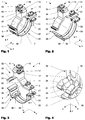
- the Figures 1-4 show a first variant of a ground terminal 1.
- the FIG. 5 shows a variant of an active compound.
- the Figures 6-7 show a second and a third variant of a ground terminal 1.
- the FIGS. 8 and 9 show a fourth variant of a ground terminal 1.
- Die FIGS. 10 to 12 show a variant of a clamping device 6.
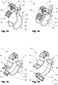
- Die Figures 13-14 show a fifth variant of a ground terminal 1.
- the FIGS. 15-16 a sixth variant of a ground terminal 1.
- a ground terminal 1 comprises, as in the Figures 1-3 . 6-9 and 13-16 shown, usually a top 10, which has a circumferentially a receiving opening 7 at least partially curved and / or kinked body 11.
- a clamping base 12 forms in the variants shown an integral part of the upper part 10.
- a clamping plate 14 is operatively connected via a clamping screw 13 with the clamping base 12.
- the clamping base 12 has a threaded hole 27, which in the sectional view according to FIG. 7 is apparent.
- a spring 15 (coil spring) which is disposed between the clamping base 12 and the clamping plate 14, pushes the clamping plate 14 away from the clamping base 12.
- other types of springs may be used, such as bending springs.
- the clamping base 13 has a bore 16 which has a larger diameter than the spring 15 and which extends over a certain length along the clamping screw 13. The bore 16 serves to receive the spring 15 when the clamping plate 14 rests on the clamping base 12. The arrangement is best in FIG.
- the clamping base 13 has in the embodiment shown two at an angle of 90 ° to each other aligned notches 17, which serve for better positioning of the grounding line 5 when clamping.
- the clamping plate 14 has a central part 24, which has a bore 25 for the clamping screw 13. Furthermore, the clamping plate 13 comprises a support element 18, which can simultaneously serve as anti-rotation.
- the support member 18 is arranged at a right angle to the central part and extends in the mounted state parallel to a side surface 19 of the clamping base 12.
- the side surface 19 serves as a stop for the support element 18.
- the interaction of the support element 18 and the side surface 19 can be prevented be that the clamping plate 14 tilts when connecting the grounding line 5 in an inadvertent manner to the rear and so the clamping is impaired.
- the clamping plate 14 also includes an obliquely downwardly projecting clamping fingers 26, which prevents the terminals of the grounding line 5 that this slips laterally from the clamping base 12.
- FIG. 10 illustrated initial state
- the support member 18 rests on the stopper 19, so that rotation of the clamping plate 14 about the axis of the clamping screw 13, relative to the clamping base 6 is prevented.
- the support element 18 acts as anti-rotation.
- the clamping plate 14 can be tilted relative to the clamping base 6.
- FIG. 11 the fit between the bore 25 and the clamping screw 13 disposed therein dimensioned so that the necessary for tipping game is guaranteed, as in FIG. 11 is illustrated.
- one of the force applied by the spring 15 opposite force must be exerted. After the clamping plate 14 is tilted enough, it can be rotated about the axis of the clamping screw 13 without the rotation of the support element 18 is blocked. After the clamping plate 14 has been rotated to the desired position, the tilting as in FIG. 12 shown terminated (indicated by the dashed arrow).
- the support member 18 By the force applied by the spring 15, the support member 18 is then pressed against a stop 19, which causes a defined alignment between the clamping plate 14 and the clamping base 6.
- the support element 18 also serves as a type of alignment element which ensures a defined alignment of the clamping plate 14 with the two notches 17 of the clamping base 12.
- the main body 11 of the upper part 10 of the ground terminal 1 generally has at least one contact surface 20, which in the assembled state for electrical contacting of a tube 4 (see. FIG. 8 ) serves. If necessary, the main body 10 can be configured deformable.
- the earthing terminal 1 comprises, in addition to the upper part 10 mentioned above, a bow-shaped lower part 30 which, in the embodiments shown, consists of a sheet-metal strip (cf. Figures 1-9 ), a wire (cf. Figures 13-14 ) or by injection molding or extrusion of plastic or metal is made (see. FIGS. 15-16 ). Together with the upper part 10, the lower part 30 encloses a receiving space for a cylindrical body, such as a pipe or a rod or the like. By tightening the operative connection means, the upper part 10 and the lower part 30 can be fixed on the cylindrical body shown.
- the base 30 is less rigid in the circumferential direction as compared to the top 10, i. it has a greater flexibility in comparison to the upper part 10, such that when it is fitted around a cylindrical counter-body 4, such as e.g. the tube 4, in the circumferential direction stronger deformed compared to the upper part 10 as the thus operatively connected upper part 10th
- the lower part 30 has two straps 39 spaced apart from each other, which, when the operative connection means 2, 3 are put on, form around the counterbody and provide a secure hold. If necessary, the two straps 39 can also be operatively connected by one or more transverse webs.
- the upper part 10 and the lower part 30 are operatively connected to each other via a first and a second operative connection means 2, 3.
- the operative connection means 2, 3 may have different configurations depending on the field of application.
- a first operative connection means 2 is designed as a hook connection.
- one or more hooks 22 are formed on the upper part 10.
- At least one loop-shaped counterpart 34 which has one or more holding rungs 35, is formed on the lower part 30. This can be hung on the hook 22 during assembly.
- the Lower part 30 may have a chamfered end portion 36, which facilitates the mounting of the two parts during assembly.
- the opposite second operative connection means 3 is designed as a screw connection.
- a clamping screw 31 is mounted on the upper part 10 in a formed as a hole or thread 21 abutment and on the lower part 30 in an operatively connected with this nut 33.
- the second operative connection means 3 advantageously offers sufficient freedom that the hook connection of the first operative connection means 2 between the upper part 10 and the lower part 30 can be easily released or suspended.
- This relative displaceability is increased in particular by a hole 21 designed as an elongated hole, which enables a displacement and tilting of the clamping screw 31 relative to the upper part 10 during assembly.
- FIG. 4 In detail, an advantageous mounting of a nut 33 on a lower part 30.
- a square nut 33 is clamped between retaining tabs 38 and beads 32 in the variant shown that relative displacements and rotations between the square nut 33 and the rest of the lower part 30 are largely locked.
- Such storage can be made particularly simple and inexpensive, since no additional joining agents are necessary.
- Other fixings are possible.
- FIG. 5 shows another variant for supporting a clamping screw 31 in the lower part 30, in which a nut 33 welded to the lower part 30, or is pressed.
- a nut can also be glued or threaded directly be formed on the lower part 30. Combinations of different joining methods or means are also possible.
- the upper part 10 and the lower part 30 are mechanically connected to each other via first and a second formed as a screw connection active connection means 2, 3.
- one side of the upper part 10 is provided with a slot 22 and the other side with a longitudinal opening 23, which serves as a one-sided aligned passage opening.
- the ground terminal 1 can be mounted on a device, without having to be completely solved for one of the two screw 2, 3.
- FIGS. 8 and 9 show on pipes 4 with different diameters mounted grounding terminals 1, wherein in each case a grounding line 5 in transverse ( FIG. 8 ), or in longitudinal circuit ( FIG. 9 ) connected. As also shown, with the clamping device 12 according to the invention, grounding lines 5 with different diameters can be contacted electrically well.
- the grounding terminals 1 each have a plurality of transverse webs 35, whereby the same embodiment can be used for connection to pipes 4 of very different diameters.
- FIGS. 13 and 14 show a variant of a ground terminal 1 according to the present invention, in which the lower part 30 is formed in the manner of a wire bracket. On the upper part 10 more than one type of saw teeth formed hooks 22 are arranged, in which the transverse web of the lower part 30 -. suitable for the diameter of the relocating pipe - can be hung as in FIG. 14 will be shown.
- FIGS. 15 and 16 show a variant of a ground terminal 1 according to the present invention, in which the lower part 30 has been produced by means of an extrusion process and is shaped so that it can be hooked on one side at a corresponding end of the upper part 2.
- the upper part 10 comprises a longitudinal opening 23 which is formed as a one-sided aligned passage opening into which the clamping screw 31 can be switched on or off (indicated by the dashed arrow in FIG FIG. 16 ).
- the clamping screw 31 is mounted in a nut 33. This has in the embodiment shown on a U-shape, which can at least partially surround the lower part 30.
- the lower part 30 has an elongated opening in which the clamping screw 31 is mounted. Thereby, the clamping screw 31 can be angled relative to the lower part 30, which facilitates hanging in the longitudinal opening 23.
Landscapes
- Clamps And Clips (AREA)
- Supports For Pipes And Cables (AREA)
- Elimination Of Static Electricity (AREA)
Abstract
Description
- Die Erfindung betrifft eine Erdungsklemme für den Potentialausgleich und/oder für die Erdung elektrischer Anlagen, Blitzschutzanlagen oder anderer Anlagen.
- Erdungsklemmen werden unter anderem zur Herstellung eines Potentialausgleichs elektrischer Installationen in Gebäuden verwendet. Ebenso finden sie Verwendung bei Blitzschutzanlagen. Aus dem Stand der Technik sind diverse Erdungsklemmen bekannt.
-
US2010227483 wurde am 09.09.2010 im Namen von Mike Vernica veröffentlicht und zeigt eine Erdungsklemme. Diese umfasst zwei bügelförmige Spannelemente, die über zwei Schrauben so miteinander verbunden sind, dass sich die Distanz der Spannelemente durch Drehung der Schrauben verringern lässt, um z.B. ein dazwischen angeordnetes Rohr zu klemmen. Ein Nachteil dieser Erdungsklemme besteht darin, dass zu ihrer Montage auf einem Rohr eine der beiden Schraubverbindungen komplett gelöst werden muss. Dadurch besteht einerseits die Gefahr, dass die freie Schraube verloren geht. Andererseits kann die anschliessende Wiederherstellung der Schraubverbindung bei eingeschränkter Zugänglichkeit am Montageort u.U. schwierig sein. -
EP1398850 A1 wurde am 17.03.2004 im Namen der AGRO AG publiziert und zeigt eine aus gebogenem Blech gefertigte Erdleitungsbride. Diese wird mit einer Schelle an einem Rohr einer Rohrleitung befestigt werden. Um Erdungsdrähte sowohl in Quer- als auch in Längsschaltung anschliessen zu können verfügt diese Erdleitungsbride über ein Klemmelement, das eine Platte als um die Achse einer mittigen Klemmschraube drehbares Klemmelement aufweist. Dieses bildet zwei Durchgänge für eine Längsbeschaltung und zwei Durchgänge für eine Querbeschaltung. -
DE7638349 U1 wurde am 31.03.1976 im Namen der Firma Hermann Kleinhuis veröffentlicht und zeigt eine Erdungsrohrschelle, die mit Rohrleitungen unterschiedlicher Durchmesser fest verbunden werden kann und sowohl geschnittene, als auch durchlaufende ungeschnittene Erdungsleitungen anschliessen soll. Die Schelle umfasst dazu zwei Teile, wobei eines der beiden Schellenteile eine über das Klemmorgan hinausgehende Verlängerung aufweist, welche die Kontaktklemme zum Anschluss einer Erdungsleitung trägt. Der untere Schellenteil ist als Flachstab mit einer quer zu seiner Längsrichtung verlaufenden Halterinne ausgebildet. Der obere Schellenteil ist im Wesentlichen winkelförmig abgebogen und hat in seinem in montiertem Zustand ein Rohr hintergreifenden Schenkel mehrere Ausnehmungen zum Eingriff einer abgekröpften Zunge des unteren Schellenteils. Durch eine Schraube lässt sich die Erdungsrohschelle auf einer Rohrleitung festklemmen. -
US5281761 wurde am 25.01.1994 im Namen der Burndy Corporation veröffentlicht und zeigt ein System zur Erdung eines elektrischen Kabels an einer - Erdungselektrode, wie etwa einer Wasserleitung. Dieses umfasst einen Oberteil mit einer Montagefläche und einem gebogenem Sattel und einen Unterteil mit mindestens einem U-Bolzen der an beiden Enden jeweils ein Gewinde aufweist. Auf der Montagefläche kann ein gecrimptes Kabelende in mehreren Winkelstellungen relativ zur Wasserleitung mittels einer Schraubverbindung befestigt werden. In auf einer Erdungselektrode montiertem Zustand umfasst der U-Bolzen gemeinsam mit dem gebogenen Sattel die Erdungselektrode, wobei die beiden Enden des U-Bolzens durch Bohrungen in dem gebogenen Sattel hindurchgehen und mittels Muttern und Unterlegscheiben mit diesem verschraubt sind. Aufgrund der Vielzahl an Schrauben, Muttern und Unterlegscheiben ist die Montage solcher Systeme relativ umständlich und es besteht die latente Gefahr, dass dabei Teile verloren oder vergessen gehen. Deshalb eignen sich solche Systeme nur beschränkt zur Montage an schlecht zugänglichen Stellen. Ebenso kann es bei solchen Systemen unter gewissen Umständen schwierig sein langfristig die für eine sichere Erdung notwendige Kontaktkraft aufrecht zu halten.
- Eine Aufgabe der Erfindung besteht darin, eine Erdungsklemme zu zeigen, welche im Vergleich zum Stand der Technik einfacher montiert werden kann und bessere Werte aufweist. Eine weitere Aufgabe der Erfindung besteht darin eine Erdungsklemme zu zeigen, welche sich für unterschiedliche Rohrdurchmesser eignet.
- Eine erfindungsgemässe Erdungsklemme weist in der Regel ein Oberteil mit einem Grundkörper und einer Klemmvorrichtung für wenigstens eine Erdungsleitung auf. Weiterhin umfasst die Erdungsklemme ein ebenfalls gekrümmtes im montierten Zustand bogenförmiges Unterteil auf, welches über ein erstes und ein zweites Wirkverbindungsmittel mit dem Oberteil wirkverbindbar ist. In wirkverbundenem Zustand bilden das Oberteil und das Unterteil eine mit Vorteil zumindest bereichsweise rundliche Aufnahmeöffnung, welche zur Aufnahme eines zylindrischen Rohres oder einer Stange dient. Das Oberteil und/oder das Unterteil können bogenförmig gekrümmt oder auch geknickt sein. Insbesondere kann das Oberteil einen gekrümmten und/oder geknickten Grundkörper aufweisen, welcher einen Teil der Aufnahmeöffnung bildet. Andere Ausgestaltungen und Querschnittsformen sind möglich. Das erste und das zweite Wirkverbindungsmittel sind sich in Bezug auf die Aufnahmeöffnung mit Vorteil im Wesentlichen diametral gegenüberliegend angeordnet. In gewissen Ausführungsformen ist das Unterteil im Vergleich zum Oberteil in Umfangsrichtung weniger steif ausgebildet, derart, dass es sich beim Anlegen um einen zylindrischen Gegenkörper abhängig von dessen Durchmesser stärker deformiert als das Oberteil.
- Je nach Ausführungsform kann das Unterteil aus Metallblech und/oder Draht und/oder Kunststoff geformt sein. Das Oberteil dient primär zur Übertragung von elektrischen Strömen. Es weist zu diesem Zweck mindestens eine im Innern der Aufnahmeöffnung liegende Kontaktfläche auf, welche zum Kontaktieren des zylindrischen Rohres oder der Stange (nachfolgend verallgemeinernd auch Gegenkörper genannt) dient. Um die zur Kontaktierung der üblichen Gegenkörper notwendige Variantenvielfalt von Erdungsklemmen zu reduzieren, ist die Kontaktfläche mit Vorteil so gestaltet, dass eine ausreichend grosse gemeinsame elektrische Kontaktfläche zwischen dem Oberteil und zu kontaktierenden Gegenkörper unterschiedlicher Dimensionen sichergestellt wird. Dies kann beispielsweise durch eine speziell gewählte konstante oder durch eine veränderliche Krümmung der Kontaktfläche, die z.B. auf die Durchmesser der gängigsten Rohrleitungen ausgerichtet ist, erzielt werden. Eine besonders gute Ausrichtung einer Erdungsklemme relativ zum Gegenkörper kann erreicht werden, wenn das Unterteil zwei zueinander beabstandete Gurten umfasst.
- Der Grundkörper des Oberteils ist mit Vorteil aus einem Material mit einer guten elektrischen Leitfähigkeit hergestellt. Gute Resultate werden mit Messing und/oder Bronze und/oder Aluminium erreicht. Das Unterteil, welches primär zur Befestigung des Oberteils dient kann aus einem Material mit einer geringeren elektrischen Leitfähigkeit hergestellt sein. In der Regel sind solche Materialien kostengünstiger, was sich positiv auf die Herstellungskosten auswirkt. Der Grundkörper des Oberteils kann in einem Strangpressverfahren und/oder einem Giessverfahren hergestellt werden. In einer bevorzugten Ausführungsform sind das Oberteil und das Unterteil über ein Wirkverbindungsmittel miteinander wirkverbunden, welches einen Haken und ein ösenförmiges Gegenstück umfasst.
- Die Klemmvorrichtung welche am Oberteil angeordnet ist und zur Klemmung einer Erdungsleitung oder dergleichen dient, weist in einer bevorzugten Ausführungsvariante einen Klemmsockel und eine mittels einer Klemmschraube am Klemmsockel befestigte Klemmplatte auf. Eine solche Klemmplatte muss nicht plattenförmig sein, sondern kann z.B. auch bogenförmig sein. Die Klemmplatte kann ein Abstützelement umfassen, welches in montiertem Zustand mit einem Anschlag des Klemmsockels zusammenwirkt, so dass beim Klemmen einer Erdungsleitung oder dergleichen ein Abkippen der Klemmplatte gegenüber dem Klemmsockel verhindert wird. In einer Variante kann die Klemmplatte um die Klemmschraube von einer ersten in eine zweite Position gedreht werden, derart, dass Erdungsleitungen in mindestens zwei unterschiedlichen Richtungen klemmbar sind. Die Klemmvorrichtung kann eine Feder aufweisen, welche als Rückstellelement dient und die Klemmplatte vom Klemmsockel wegdrückt. Eine solche Ausgestaltung der Erfindung kann vorteilhaft sein, da so sichergestellt wird, dass die Klemmplatte und der Klemmsockel bis zur eigentlichen Klemmung voneinander getrennt bleiben, so dass eine Erdungsleitung einfach eingeführt werden kann. Die Feder kann z.B. eine Spiralfeder, respektive eine Schraubenfeder sein, wodurch eine einfache Fertigung der Erdungsklemme möglich wird. Andere Federtypen, wie z.B. Biegefedern, sind möglich. Details zur Ausgestaltung und der Funktionsweise werden nachfolgend näher erläutert.
- Falls gewünscht, so kann die Klemmplatte ein gebogenes Blechteil umfassen. Dadurch können einerseits die Herstellungskosten gesenkt werden und andererseits kann ein zuverlässiger elektrischer Anschluss sichergestellt werden, da so u.a. auf einfache Weise ein Aufspleissen verseilter oder verlitzter Erdungsleitungen beim Klemmen weitgehend reduziert werden kann.
- Ein Klemmsockel kann wenigstens eine Kerbe umfassen. Eine solche Kerbe kann einerseits die Positionierung/Ausrichtung einer zu klemmenden Erdungsleitung verbessern und andererseits auch den elektrischen Kontakt zwischen einer Erdungsleitung und einer Klemmvorrichtung verbessern. Die Kerbe kann dazu direkt im Grundkörper angeordnet sein.
- In einer Variante der Erfindung kann der Klemmsockel mehrere Kerben aufweisen. In einer Variante der Erfindung umfasst die Klemmsockel zwei Kerben, wobei die erste Kerbe im Wesentlichen parallel zur Längsachse eines zu kontaktierenden Gegenkörpers ausgerichtet ist und die zweite Kerbe im Wesentlichen senkrecht auf die erste Kerbe steht. Jedoch ist die vorliegende Erfindung nicht auf eine solche Anzahl und Ausrichtung von Kerben beschränkt. Ebenso kann auch eine Klemmplatte wenigstens eine Kerbe aufweisen.
- Eine einfach herstellbare Erdungsklemme mit einer elektrisch vorteilhaften Kontaktierung kann erzielt werden, wenn der Grundkörper des Oberteils und der Klemmsockel einstückig ausgebildet sind.
- Um die Klemmung einer Erdungsleitung zu vereinfachen kann die Klemmplatte eine bei Bedarf lösbare Verdrehsicherung aufweisen, die eine Drehung der Klemmplatte um die Klemmschraube verhindert. Dadurch kann eine gewünschte relative Ausrichtung der Klemmplatte zum Klemmsockel sichergestellt werden, sowohl bevor eine Erdungsleitung geklemmt wird, als auch während der Erzeugung einer solchen Klemmung. Insbesondere kann so sichergestellt werden, dass die Klemmplatte beim Eindrehen einer Klemmschraube nicht mitgedreht wird. Eine besonders effiziente und gleichzeitig einfache Verdrehsicherung kann erzeugt werden, wenn ein Abstützelement gleichzeitig als Verdrehsicherung wirkt. Durch die Verwendung eines im Vergleich zum Oberteil einfacher deformierbaren Unterteils kann verhindert werden, dass die Erdungsklemme bei plötzlich auftretenden hohen elektrischen Strömen wegen der resultierenden Ausdehnung aufgrund der jouleschen Wärme mechanisch beschädigt wird, da ein solches Unterteil die auftretenden Verformungen aufnehmen kann ohne beschädigt zu werden. Solch hohe Ströme können beispielsweise bei Blitzschutzanlagen auftreten.
- Eine einfache Herstellung kann erreicht werden, wenn das Unterteil wenigstens teilweise aus einem Blech hergestellt wird. Dadurch können Unterteile in grosser Stückzahl kostengünstig z.B. mittels Stanz- und Biegeprozessen hergestellt werden. Sowohl gute elektrische Eigenschaften als auch eine hohe chemische Beständigkeit und einfache Fertigung kann erreicht werden, wenn das Oberteil, bzw. sein Grundkörper, aus einer Messinglegierung hergestellt wird. Die Erfindung ist jedoch nicht auf diese Materialien beschränkt und es ist auch eine Fertigung aus Kupfer, Bronze, Aluminium oder anderen geeigneten Materialien möglich. Um z.B. die Korrosionsbeständigkeit zu erhöhen sind auch Beschichtungen möglich, z.B. mit Zinn.
- Besonders bedienfreundliche Erdungsklemmen können erzielt werden, wenn das Oberteil und das Unterteil mit einer Hakenverbindung sowie einer Schraubenverbindung mit einer Spannschraube miteinander wirkverbunden werden, wie nachfolgend genauer erläutert ist. Auf diese Weise kann eine Erdungsklemme relativ rasch montiert werden, und die einzelnen Teile bleiben während des ganzen Montagevorgangs verliersicher miteinander verbunden. Eine gute Adaptierbarkeit auf Gegenkörper unterschiedlicher Formen kann erreicht werden, wenn das Oberteil und das Unterteil über eine Hakenverbindung miteinander wirkverbunden werden, wobei eines der beiden Teile über mehrere Haken verfügt und das andere wenigstens einen in diese Haken einhängbaren Quersteg aufweist. Auf diese Weise kann eine Erdungsklemme bei der Montage auf besonders einfache Weise um einen Gegenkörper gelegt und an dessen Querschnitt angepasst werden, wie nachfolgend noch genauer erläutert ist.
- Alternativ oder in Ergänzung kann eine Erdungsklemme auch mehrere Querstege aufweisen, die mit einem oder mit mehreren Haken verbunden werden können.
- Für besondere Anwendungen ist es erfindungsgemäss vorteilhaft, wenn das Oberteil und das Unterteil durch wenigstens eine Spannschraube, welche in einer Längsöffnung gelagert ist, miteinander wirkverbunden sind. Dadurch kann eine besonders hohe Verstellbarkeit zwischen dem ersten und dem Unterteils erreicht werden. Eine solche Längsöffnung kann auch eine einseitig fluchtende Durchtrittsöffnung sein.
- Eine besonders gute Verankerung einer Spannschraube am Unterteil kann erreicht werden, wenn diese am Unterteil in einer mit diesem wirkverbundenen Mutter gelagert ist. Eine solche Mutter kann mit dem Unterteil z.B. verschweisst, verlötet , verpresst oder verklebt sein. Es sind auch Kombinationen solcher Fügeverfahren möglich.
- Die hierin beschriebene Erfindung ist nicht auf die Verwendung zur Kontaktierung von Rohren beschränkt, sondern kann auch zur Kontaktierung anderer Gegenstände, wie etwa von Profilen, verwendet werden. Ebenso können die erfindungsgemässen Erdungsklemmen insbesondere im Rahmen von Blitzschutzanlagen etwa zur Kontaktierung von Fallrohren verwendet werden.
- Anhand der in den nachfolgenden Figuren gezeigten Ausführungsbeispiele und der dazugehörigen Beschreibung werden Aspekte der Erfindung näher erläutert. Es zeigen:
- Fig. 1
- eine erste Ausführungsform einer Erdungsklemme in geschlossenem Zustand;
- Fig. 2
- die Erdungsklemme aus
Fig. 1 in geöffnetem Zustand; - Fig. 3
- die Erdungsklemme aus
Fig. 2 in einer anderen Ansicht; - Fig. 4
- eine Ausführungsform eines Wirkverbindungsmittels;
- Fig. 5
- eine erste Ausführungsform eines Wirkverbindungsmittels;
- Fig. 6
- eine zweite Ausführungsform einer Erdungsklemme;
- Fig. 7
- eine dritte Ausführungsform einer Erdungsklemme in einer teilweise geschnittenen Darstellung;
- Fig. 8
- eine vierte Ausführungsform einer Erdungsklemme montiert an einem ersten Rohr;
- Fig. 9
- die Erdungsklemme gemäss
Figur 8 montiert an einem zweiten Rohr mit einem kleineren Durchmesser; - Fig. 10
- eine Ausführungsform einer Klemmvorrichtung für ein Kabel in einem ersten Zustand;
- Fig. 11
- die Klemmvorrichtung aus
Fig. 10 in einem teilweise gedrehten Zustand; - Fig. 12
- die Klemmvorrichtung aus
Fig. 10 in einem zweiten Zustand; - Fig. 13
- eine fünfte Ausführungsform einer Erdungsklemme in geöffnetem Zustand;
- Fig. 14
- die Erdungsklemme aus
Fig. 13 in geschlossenem Zustand; - Fig. 15
- eine sechste Ausführungsform einer Erdungsklemme in geschlossenem Zustand;
- Fig. 16
- die Erdungsklemme aus
Fig. 15 in geöffnetem Zustand. - In den nachfolgenden Figuren und der dazugehörigen Beschreibung sind sich entsprechende Teile, soweit nichts anderes vermerkt ist, mit gleichen Bezugszeichen versehen.
- Die
Figuren 1-4 zeigen eine erste Variante einer Erdungsklemme 1. DieFigur 5 zeigt eine Variante eines Wirkverbindungsmittels. DieFiguren 6-7 zeigen eine zweite und eine dritte Variante einer Erdungsklemme 1. DieFiguren 8 und9 zeigen eine vierte Variante einer Erdungsklemme 1. DieFiguren 10 bis 12 zeigen eine Variante einer Klemmvorrichtung 6. DieFiguren 13-14 zeigen eine fünfte Variante einer Erdungsklemme 1. DieFiguren 15-16 eine sechste Variante einer Erdungsklemme 1. - Eine Erdungsklemme 1 umfasst, wie in den
Figuren 1-3 ,6-9 und13-16 gezeigt, in der Regel ein Oberteil 10, welches einen in Umfangsrichtung einer Aufnahmeöffnung 7 zumindest bereichsweise gekrümmten und/oder geknickten Grundkörper 11 aufweist. Ein Klemmsockel 12 bildet in den gezeigten Varianten einen integralen Bestandteil des Oberteils 10. Eine Klemmplatte 14 ist über eine Klemmschraube 13 mit dem Klemmsockel 12 wirkverbunden. Der Klemmsockel 12 weist ein Gewindeloch 27 auf, welches in der Schnittdarstellung gemässFigur 7 ersichtlich ist. Der Klemmsockel 12 und die Klemmplatte 14 bilden zusammen mit der Klemmschraube 13 Teil einer Klemmvorrichtung 6 für mindestens eine Erdungsleitung 5. Mittels Drehung der Klemmschraube 13 kann der Abstand zwischen dem Klemmsockel 12 und der Klemmplatte 14 verstellt werden, so dass eine Erdungsleitung 5 dazwischen eingeklemmt werden kann (vgl.Figuren 8- 12). Eine Feder 15 (Schraubenfeder) welche zwischen dem Klemmsockel 12 und der Klemmplatte 14 angeordnet ist, drückt die Klemmplatte 14 weg vom Klemmsockel 12. Alternativ können bei einer Erdungsklemme der gezeigten Ausführungsform auch andere Arten von Federn verwendet werden, wie z.B. Biegefedern. Dadurch wird die Montage erleichtert, da der Klemmsockel 12 und die Klemmplatte 14 vor dem Einbringen einer Erdungsleitung 5 nicht von Hand auseinandergerückt werden müssen. Der Klemmsockel 13 weist eine Bohrung 16 auf, die einen grösseren Durchmesser als die Feder 15 aufweist und welche sich über eine gewisse Länger entlang der Klemmschraube 13 erstreckt. Die Bohrung 16 dient zur Aufnahme der Feder 15, wenn die Klemmplatte 14 auf dem Klemmsockel 12 aufliegt. Die Anordnung ist am besten inFigur 7 ersichtlich, wo die Klemmvorrichtung 6 teilweise geschnitten dargestellt ist, damit das Innenleben sichtbar wird. Der Klemmsockel 13 weist in der gezeigten Ausführungsform zwei in einem Winkel von 90° zueinander ausgerichtete Kerben 17 auf, welche zur besseren Positionierung der Erdungsleitung 5 beim Klemmen dienen. Die Klemmplatte 14 weist ein Mittelteil 24 auf, welches eine Bohrung 25 für die Klemmschraube 13 aufweist. Weiterhin umfasst die Klemmplatte 13 ein Abstützelement 18, welches gleichzeitig als Verdrehsicherung dienen kann. Das Abstützelement 18 ist gegenüber dem Mittelteil in einem rechten Winkel angeordnet und erstreckt sich im montierten Zustand parallel zu einer Seitenfläche 19 des Klemmsockels 12. Die Seitenfläche 19 dient als Anschlag für das Abstützelement 18. Durch das Zusammenwirken des Abstützelementes 18 und der Seitenfläche 19 kann verhindert werden, dass die Klemmplatte 14 beim Klemmen der Erdungsleitung 5 in ungewollter Weise nach hinten abkippt und so die Klemmung beeinträchtigt. In der gezeigten Variante umfasst die Klemmplatte 14 zudem einen schräg nach unten abstehenden Klemmfinger 26, welcher beim Klemmen der Erdungsleitung 5 verhindert, dass diese vom Klemmsockel 12 seitlich abrutscht. - Ein Vorteil der gezeigten Klemmvorrichtung 6 besteht darin, dass diese zur Klemmung von Erdungsleitungen in unterschiedlichen Richtungen (x- und y-Richtung) geeignet ist. In den
Figuren 10-12 wird schematisch gezeigt, wie eine Klemmvorrichtung 6 von einem ersten Zustand, der beispielsweise eine Längsschaltung von einer Erdungsleitung 5 ermöglicht, in einen zweiten Zustand, der beispielsweise eine Querschaltung ermöglicht, gebracht werden kann. Im inFigur 10 dargestellten Ausgangszustand liegt das Abstützelement 18 auf dem Anschlag 19 auf, so dass eine Drehung der Klemmplatte 14 um die Achse der Klemmschraube 13, relativ zum Klemmsockel 6 verhindert wird. Damit wirkt das Abstützelement 18 als Verdrehsicherung. Wie durch den gestrichelten Pfeil angedeutet ist, kann die Klemmplatte 14 gegenüber dem Klemmsockel 6 abgekippt werden. Um eine solche Abkippung zu ermöglichen kann wie gezeigt z.B. die Passung zwischen der Bohrung 25 und der darin angeordneten Klemmschraube 13 so dimensioniert werden, dass das zum Abkippen notwendige Spiel gewährleistet ist, wie inFigur 11 illustriert ist. Um die Klemmplatte 14 abkippen zu können, muss eine der von der Feder 15 aufgebrachten Kraft entgegen gesetzte Kraft ausgeübt werden. Nachdem die Klemmplatte 14 genügend abgekippt ist, kann sie um die Achse der Klemmschraube 13 gedreht werden, ohne dass die Drehung vom Abstützelement 18 blockiert wird. Nachdem die Klemmplatte 14 bis in die gewünschte Stellung gedreht wurde kann die Abkippung wie inFigur 12 gezeigt beendet werden (angedeutet durch den gestrichelten Pfeil). Durch die von der Feder 15 aufgebrachte Kraft wird das Abstützelement 18 danach an einen Anschlag 19 gedrückt, was eine definierte Ausrichtung zwischen der Klemmplatte 14 und dem Klemmsockel 6 bewirkt. Somit dient das Abstützelement 18 in der gezeigten Ausführungsform auch als eine Art von Ausrichtungselement, das eine definierte Ausrichtung der Klemmplatte 14 zu den beiden Kerben 17 des Klemmsockels 12 sicherstellt. - Der Grundkörper 11 des Oberteils 10 der Erdungsklemme 1 weist in der Regel mindestens eine Kontaktfläche 20 auf, die in montiertem Zustand zur elektrischen Kontaktierung eines Rohres 4 (vgl.
Figur 8 ) dient. Bei Bedarf kann der Grundkörper 10 deformierbar ausgestaltet sein. Die Erdungsklemme 1 umfasst neben dem eingangs erwähnten Oberteil 10 ein bügelförmiges Unterteil 30, das in den gezeigten Ausführungsformen aus einem Blechstreifen (vgl.Figuren 1-9 ), einem Draht (vgl.Figuren 13-14 ) oder durch Spritzgiessen oder Strangpressen aus Kunststoff oder Metall hergestellt ist (vgl.Figuren 15-16 ). Gemeinsam mit dem Oberteil 10 umschliesst das Unterteil 30 einen Aufnahmeraum für einen zylindrischen Körper, wie z.B. ein Rohr oder eine Stange oder dergleichen. Durch Anziehen der Wirkverbindungsmittel können das Oberteil 10 und das Unterteil 30 auf dem gezeigten zylindrischen Körper befestigt werden. - In gewissen Anwendungsgebieten werden gute Resultate erreicht, wenn das Unterteil 30 in Umgangsrichtung im Vergleich zum Oberteil 10 weniger steif ausgebildet, d.h. es weist im Vergleich zum Oberteil 10 eine grössere Flexibilität auf, derart, dass sich dieses beim Anlegen um einen zylindrischen Gegenkörper 4, wie z.B. das Rohr 4, im Vergleich zum Oberteil 10 in Umfangsrichtung stärker deformiert als das damit wirkverbundene Oberteil 10.
- In einer bevorzugten Ausführungsform weist das Unterteil 30 zwei zueinander beabstandete Gurten 39 auf, welche beim Anziehen der Wirkverbindungsmittel 2, 3 sich um den Gegenkörper anlegen und einen sicheren Halt bieten. Bei Bedarf können die beiden Gurten 39 auch durch einen oder mehrere Querstege wirkverbunden sein.
- Das Oberteil 10 und das Unterteil 30 werden über ein erstes und ein zweites Wirkverbindungsmittel 2, 3 miteinander wirkverbunden. Wie in den Figuren ersichtlich können die Wirkverbindungsmittel 2, 3 je nach Anwendungsgebiet unterschiedliche Ausgestaltungen aufweisen.
- Für eine besonders einfache Montage ist ein erste Wirkverbindungsmittel 2 als Hakenverbindung ausgebildet ist. Bei den Ausführungsformen gemäss den
Figuren 1-4 ,8 und9 sowie denFiguren 13-14 sind einer oder mehrere Haken 22 am Oberteil 10 ausgebildet. Am Unterteil 30 ist mindestens ein ösenförmiges Gegenstück 34 ausgebildet, welches eine oder mehrere Haltesprossen 35 aufweist. Dieses kann bei der Montage am Haken 22 eingehängt werden. Das Unterteil 30 kann einen angefasten Endbereich 36 aufweisen, der während der Montage das Einhängen der beiden Teile erleichtert. - Eine einfache Montage wird möglich, wenn das gegenüberliegende zweite Wirkverbindungsmittel 3 als Schraubverbindung ausgebildet ist. Dazu ist eine Spannschraube 31 am Oberteil 10 in einem als Loch oder Gewinde 21 ausgebildeten Widerlager und am Unterteil 30 in einer mit diesem wirkverbundenen Mutter 33 gelagert. Das zweite Wirkverbindungsmittel 3 bietet im gelösten Zustand mit Vorteil ausreichend Spielraum, dass die Hakenverbindung des ersten Wirkverbindungsmittels 2 zwischen dem Oberteil 10 und dem Unterteil 30 einfach gelöst, bzw. eingehängt werden können. Diese relative Verschiebbarkeit wird insbesondere durch ein als Langloch ausgebildetes Loch 21 erhöht, die bei der Montage ein Verschieben und Abkippen der Spannschraube 31 gegenüber dem Oberteil 10 ermöglicht.
- Die
Figur 4 zeigt im Detail eine vorteilhafte Lagerung einer Mutter 33 an einem Unterteil 30. Dazu ist bei der gezeigten Variante eine Vierkantmutter 33 so zwischen Haltelaschen 38 und Sicken 32 eingeklemmt, dass relative Verschiebungen und Drehungen zwischen der Vierkantmutter 33 und dem restlichen Unterteil 30 weitgehend gesperrt sind. Eine solche Lagerung kann besonders einfach und kostengünstig hergestellt werden, da keine zusätzlichen Fügemittel notwendig sind. Andere Befestigungen sind möglich.Figur 5 zeigt eine andere Variante zur Lagerung einer Spannschraube 31 im Unterteil 30, bei der eine Mutter 33 mit dem Unterteil 30 verschweisst, bzw. verpresst ist. Alternativ kann eine Mutter auch geklebt werden oder ein Gewinde kann direkt am Unterteil 30 angeformt sein. Es sind auch Kombinationen unterschiedlicher Fügeverfahren, bzw. -mittel, möglich. DieFiguren 6 und 7 zeigen weitere Varianten von ersten und zweiten Wirkverbindungsmitteln 2, 3. Das Oberteil 10 und das Unterteil 30 sind über erste und eine zweite als Schraubverbindungen ausgebildete Wirkverbindungsmittel 2, 3 mechanisch miteinander wirkverbunden. Bei der inFigur 7 dargestellten Ausführungsform 1 ist eine Seite des Oberteils 10 mit einem Langloch 22 und die andere Seite mit einer Längsöffnung 23 versehen, welche als einseitig fluchtende Durchtrittsöffnung dient. Dadurch kann die Erdungsklemme 1 auf einer Vorrichtung montiert werden, ohne dass dafür eine der beiden Schraubverbindungen 2, 3 ganz gelöst werden muss. - Die
Figuren 8 und9 zeigen auf Rohrleitungen 4 mit unterschiedlichen Durchmessern montierte Erdungsklemmen 1, wobei jeweils eine Erdungsleitung 5 in Quer- (Figur 8 ), bzw. in Längsschaltung (Figur 9 ) angeschlossen ist. Wie ebenfalls gezeigt ist, können mit der erfindungsgemässen Klemmvorrichtung 12 Erdungsleitungen 5 mit unterschiedlichem Durchmesser gut elektrisch kontaktiert werden. Die Erdungsklemmen 1 verfügen jeweils über mehrere Querstege 35, wodurch dieselbe Ausführungsform zum Anschluss an Rohre 4 sehr unterschiedlicher Durchmesser verwendet werden kann. - Die
Figuren 13 und 14 zeigen eine Variante einer Erdungsklemme 1 gemäss der vorliegenden Erfindung, bei welcher das Unterteil 30 in der Art eines Drahtbügels ausgebildet ist. Auf dem Oberteil 10 sind mehrere als eine Art Sägezähne ausgebildete Haken 22 angeordnet, in welche der Quersteg des Unterteils 30 - passend zum Durchmesser des umzugreifenden Rohrs - eingehängt werden kann, wie inFigur 14 gezeigt wird. - Die
Figuren 15 und 16 zeigen eine Variante einer Erdungsklemme 1 gemäss der vorliegenden Erfindung, bei welcher das Unterteil 30 mittels eines Strangpressverfahrens hergestellt wurde und so geformt ist, dass es einseitig an einem korrespondierenden Ende des Oberteils 2 eingehängt werden kann. Das Oberteil 10 umfasst eine Längsöffnung 23, welche als einseitig fluchtende Durchtrittsöffnung ausgebildet ist, in welche die Spannschraube 31 ein- bzw. ausgehängt werden kann (angedeutet mit dem gestrichelten Pfeil inFigur 16 ). Am Unterteil 30 ist die Spannschraube 31 in einer Mutter 33 gelagert. Diese weist in der gezeigten Ausführungsform eine U-Form auf, welche das Unterteil 30 wenigstens teilweise umgreifen kann. Dadurch kann ein Formschluss zwischen Unterteil 30 und Mutter 33 erzeugt werden, der beim Ein-, bzw. Ausschrauben, der Spannschraube 31 eine Mitrotieren der Mutter 33 verhindert. Ebenfalls weist das Unterteil 30 eine längliche Öffnung auf, in der die Spannschraube 31 gelagert ist. Dadurch kann die Spannschraube 31 gegenüber dem Unterteil 30 abgewinkelt werden, was das Einhängen in der Längsöffnung 23 erleichtert.BEZUGSZEICHEN 1 Erdungsklemme 22 Haken 2 Erstes Wirkverbindungsmittel 23 Längsöffnung 3 Zweites Wirkverbindungsmittel 24 Mittelteil (Klemmplatte) 4 Rohr (Gegenkörper) 25 Bohrung (Klemmplatte) 5 Erdungsleitung 26 Klemmfinger (Klemmplatte) 6 Klemmvorrichtung 27 Gewindeloch 7 Aufnahmeöffnung 30 Unterteil 10 Oberteil 31 Spannschraube 11 Grundkörper 32 Sicke 12 Klemmsockel 33 Mutter 13 Klemmschraube 34 Ösenförmiges Gegenstück 14 Klemmplatte 35 Quersteg (Sprossen, Öffnung für Haken) 15 Feder 16 Bohrung 36 Endbereich 17 Kerbe 37 Öffnung für Hacken 18 Abstützelement / Verdrehsicherung 38 Haltelaschen (Mutter) 39 Gurten (Unterteil) 19 Anschlag 20 Kontaktfläche 21 Loch (Langloch)
Claims (14)
- Erdungsklemme (1) mita. einem Oberteil (10) mit einen Grundkörper (11) und einer Klemmvorrichtung (6) für wenigstens eine Erdungsleitung (5) sowieb. einem Unterteil (30), welches über ein erstes und ein zweites Wirkverbindungsmittel (2, 3) mit dem Oberteil (10) wirkverbindbar ist, wobeic. das Oberteil (10) und das Unterteil (30) in wirkverbundenem Zustand eine Aufnahmeöffnung umschliessen.
- Erdungsklemme (1) nach Anspruch 1, dadurch gekennzeichnet, dass das Unterteil (30) im Vergleich zum Oberteil (10) in Umfangsrichtung weniger steif ausgebildet ist, derart, dass es sich beim Anlegen um einen zylindrischen Gegenkörper (4) abhängig von dessen Durchmesser stärker deformiert als das Oberteil (30).
- Erdungsklemme (1) nach einem der vorangehenden Patentansprüche, dadurch gekennzeichnet, dass das Oberteil (10) einen gekrümmten und/oder geknickten Grundkörper (11) aufweist, welcher einen Teil der Aufnahmeöffnung bildet.
- Erdungsklemme (1) nach einem der vorangehenden Patentansprüche, dadurch gekennzeichnet, dass das Unterteil (30) aus Metallblech und/oder Draht und/oder Kunststoff geformt ist.
- Erdungsklemme (1) nach einem der vorangehenden Patentansprüche, dadurch gekennzeichnet, dass das Unterteil (30) zwei zueinander beabstandete Gurten (39) umfasst.
- Erdungsklemme (1) nach einem der vorangehenden Patentansprüche, dadurch gekennzeichnet, dass das Oberteil (10) aus Messing und/oder Bronze und/oder Aluminium besteht.
- Erdungsklemme (1) nach einem der vorangehenden Ansprüche, dadurch gekennzeichnet, dass das Oberteil (10) mindestens eine Kontaktfläche (20) zum Kontaktieren des Gegenkörpers (4) aufweist.
- Erdungsklemme (1) nach einem der vorangehenden Ansprüche, dadurch gekennzeichnet, dass das der Grundkörper (11) in einem Strangpressverfahren und/oder einem Giessverfahren hergestellt ist.
- Erdungsklemme (1) nach einem der vorangehenden Ansprüche, dadurch gekennzeichnet, dass das Oberteil (10) und das Unterteil (30) zumindest auf einer Seite ein Wirkverbindungsmittel (2) aufweist, welches einen Haken (22) und ein ösenförmiges Gegenstück (34) umfasst.
- Klemmvorrichtung (6) für eine Erdungsklemme (1) nach einem der vorangehenden Ansprüche, dadurch gekennzeichnet, dass die Klemmvorrichtung (6) einen Klemmsockel (12) und eine mittels einer Klemmschraube (13) am Klemmsockel (12) befestigte Klemmplatte (14) aufweist.
- Klemmvorrichtung (6) nach Anspruch 10, dadurch gekennzeichnet, dass die Klemmplatte (14) ein Abstützelement (18) umfasst, welches in montiertem Zustand mit einem Anschlag (19) des Klemmsockels (12) zusammenwirkt, so dass ein Abkippen der Klemmplatte (14) gegenüber dem Klemmsockel (12) verhindert wird.
- Klemmvorrichtung (6) nach Anspruch 10 oder 11, dadurch gekennzeichnet, dass die Klemmplatte (14) um die Klemmschraube (13) von einer ersten in eine zweite Position drehbar ist, derart, dass Erdungsleitungen (5) in mindestens zwei unterschiedlichen Richtungen klemmbar sind.
- Klemmvorrichtung (6) nach einem der Ansprüche 10 bis 12, dadurch gekennzeichnet, dass die Klemmvorrichtung (6) eine Feder (15) aufweist, welche die Klemmplatte (14) vom Klemmsockel (12) wegdrückt.
- Erdungsklemme (1) mit einer Klemmvorrichtung nach einem der Ansprüche 10 bis 13.
Priority Applications (1)
| Application Number | Priority Date | Filing Date | Title |
|---|---|---|---|
| PL16165919T PL3096407T3 (pl) | 2015-05-20 | 2016-04-19 | Zacisk uziemiający |
Applications Claiming Priority (1)
| Application Number | Priority Date | Filing Date | Title |
|---|---|---|---|
| CH00700/15A CH711109B1 (de) | 2015-05-20 | 2015-05-20 | Klemmvorrichtung für eine Erdungsklemme und Erdungsklemme. |
Publications (2)
| Publication Number | Publication Date |
|---|---|
| EP3096407A1 true EP3096407A1 (de) | 2016-11-23 |
| EP3096407B1 EP3096407B1 (de) | 2018-06-06 |
Family
ID=56026641
Family Applications (1)
| Application Number | Title | Priority Date | Filing Date |
|---|---|---|---|
| EP16165919.8A Active EP3096407B1 (de) | 2015-05-20 | 2016-04-19 | Erdungsklemme |
Country Status (4)
| Country | Link |
|---|---|
| EP (1) | EP3096407B1 (de) |
| CH (1) | CH711109B1 (de) |
| DE (1) | DE202016008620U1 (de) |
| PL (1) | PL3096407T3 (de) |
Cited By (5)
| Publication number | Priority date | Publication date | Assignee | Title |
|---|---|---|---|---|
| CN106848645A (zh) * | 2017-04-19 | 2017-06-13 | 广州番禺电缆集团有限公司 | 一种销接式电表接线夹 |
| CN109616783A (zh) * | 2019-01-22 | 2019-04-12 | 天津市管道工程集团有限公司 | 一种钢管接地线机构 |
| CN112531361A (zh) * | 2020-10-23 | 2021-03-19 | 广西电网有限责任公司北海供电局 | 一种新型圆管母线接地线挂接装置 |
| CN112750650A (zh) * | 2021-01-07 | 2021-05-04 | 余姚市超力电力电器有限公司 | 一种户外隔离开关的接地装置 |
| CN114322574A (zh) * | 2021-12-22 | 2022-04-12 | 芜湖福记恒机械有限公司 | 一种闪速炉中的异形铜水套及其浇铸成型工艺 |
Families Citing this family (2)
| Publication number | Priority date | Publication date | Assignee | Title |
|---|---|---|---|---|
| CN109449618B (zh) * | 2018-11-07 | 2023-10-20 | 云南电网有限责任公司曲靖供电局 | 接地线组件 |
| US11649910B2 (en) | 2020-03-06 | 2023-05-16 | Erico International Corporation | Systems and methods for a clamp |
Citations (6)
| Publication number | Priority date | Publication date | Assignee | Title |
|---|---|---|---|---|
| US2533897A (en) * | 1946-05-10 | 1950-12-12 | Morris D Reddock | Ground clamp |
| DE7638349U1 (de) | 1976-12-08 | 1977-03-31 | Fa. Herman Kleinhuis, 5880 Luedenscheid | Erdungsrohrschelle |
| US5281761A (en) | 1992-02-25 | 1994-01-25 | Burndy Corporation | Grounding pipe/water pipe with compression connectors |
| EP1398850A1 (de) | 2002-09-05 | 2004-03-17 | Agro Ag | Erdleitungsbride |
| US7780461B1 (en) * | 2009-03-03 | 2010-08-24 | Mike Vernica | Midpoint cable electrical ground clamp |
| US20120088380A1 (en) * | 2010-10-07 | 2012-04-12 | Smith Lawrence J | Electric ground clamp with pivoted jaws and single attached adjusting bolt and terminal block |
Family Cites Families (1)
| Publication number | Priority date | Publication date | Assignee | Title |
|---|---|---|---|---|
| CH705346A2 (de) * | 2011-08-04 | 2013-02-15 | Agro Ag | Erdungsklemme. |
-
2015
- 2015-05-20 CH CH00700/15A patent/CH711109B1/de unknown
-
2016
- 2016-04-19 DE DE202016008620.1U patent/DE202016008620U1/de not_active Expired - Lifetime
- 2016-04-19 PL PL16165919T patent/PL3096407T3/pl unknown
- 2016-04-19 EP EP16165919.8A patent/EP3096407B1/de active Active
Patent Citations (7)
| Publication number | Priority date | Publication date | Assignee | Title |
|---|---|---|---|---|
| US2533897A (en) * | 1946-05-10 | 1950-12-12 | Morris D Reddock | Ground clamp |
| DE7638349U1 (de) | 1976-12-08 | 1977-03-31 | Fa. Herman Kleinhuis, 5880 Luedenscheid | Erdungsrohrschelle |
| US5281761A (en) | 1992-02-25 | 1994-01-25 | Burndy Corporation | Grounding pipe/water pipe with compression connectors |
| EP1398850A1 (de) | 2002-09-05 | 2004-03-17 | Agro Ag | Erdleitungsbride |
| US7780461B1 (en) * | 2009-03-03 | 2010-08-24 | Mike Vernica | Midpoint cable electrical ground clamp |
| US20100227483A1 (en) | 2009-03-03 | 2010-09-09 | Mike Vernica | Midpoint cable electrical ground clamp |
| US20120088380A1 (en) * | 2010-10-07 | 2012-04-12 | Smith Lawrence J | Electric ground clamp with pivoted jaws and single attached adjusting bolt and terminal block |
Cited By (8)
| Publication number | Priority date | Publication date | Assignee | Title |
|---|---|---|---|---|
| CN106848645A (zh) * | 2017-04-19 | 2017-06-13 | 广州番禺电缆集团有限公司 | 一种销接式电表接线夹 |
| CN106848645B (zh) * | 2017-04-19 | 2023-02-28 | 广州番禺电缆集团有限公司 | 一种销接式电表接线夹 |
| CN109616783A (zh) * | 2019-01-22 | 2019-04-12 | 天津市管道工程集团有限公司 | 一种钢管接地线机构 |
| CN109616783B (zh) * | 2019-01-22 | 2023-08-29 | 天津市管道工程集团有限公司 | 一种钢管接地线机构 |
| CN112531361A (zh) * | 2020-10-23 | 2021-03-19 | 广西电网有限责任公司北海供电局 | 一种新型圆管母线接地线挂接装置 |
| CN112750650A (zh) * | 2021-01-07 | 2021-05-04 | 余姚市超力电力电器有限公司 | 一种户外隔离开关的接地装置 |
| CN114322574A (zh) * | 2021-12-22 | 2022-04-12 | 芜湖福记恒机械有限公司 | 一种闪速炉中的异形铜水套及其浇铸成型工艺 |
| CN114322574B (zh) * | 2021-12-22 | 2023-12-12 | 芜湖福记恒机械有限公司 | 一种闪速炉中的异形铜水套及其浇铸成型工艺 |
Also Published As
| Publication number | Publication date |
|---|---|
| DE202016008620U1 (de) | 2018-09-13 |
| PL3096407T3 (pl) | 2019-02-28 |
| EP3096407B1 (de) | 2018-06-06 |
| CH711109A2 (de) | 2016-11-30 |
| CH711109B1 (de) | 2020-03-13 |
Similar Documents
| Publication | Publication Date | Title |
|---|---|---|
| EP3096407B1 (de) | Erdungsklemme | |
| DE69815744T2 (de) | Rotierende Erdungskupplung zum äusseren Erden von Gehäusen | |
| DE4142642C2 (de) | Rohr/Draht-Klemmanordnung | |
| WO2012072318A1 (de) | Haltevorrichtung zum halten eines kabels | |
| DE202012102394U1 (de) | Befestigungselement | |
| EP2200122A2 (de) | Anschlussvorrichtung zum Anschluss eines Mehrlitzenleiters | |
| DE202015102037U1 (de) | Konstruktionsklemme | |
| DE102011050212A1 (de) | Kompensationsklemme | |
| DE102011108123A1 (de) | Kabelanschlussbauteil sowie Kabelanschlusseinrichtung und Kabelverbindungseinrichtung mit einem Kabelanschlussbauteil | |
| EP3539183B1 (de) | Kontaktelement mit einem klemmenden anschluss für litzenleiter | |
| DE202018104252U1 (de) | Blitzschutz- und Erdungsklemme | |
| EP2037164B1 (de) | Rohrschelle | |
| DE3044007A1 (de) | Verbindungsvorrichtung zur verankerung und befestigung von leitungen, heizkoerpern von schwerkraftwarmwasserheizungsanlagen u.dgl. an mauerwerken, wie waenden, decken u.dgl. | |
| DE102007052935B4 (de) | Steckelement zum mechanischen Fixieren von Rohren an einem Gehäuse sowie zum Bereitstellen eines Anschlusses für die Kontaktierung eines Schutzleiters | |
| DE102010017440A1 (de) | Kabeldurchführung für einen Durchbruch in einer Wandung | |
| DE102012202240A1 (de) | Klemmkörper für eine Anschlussklemme | |
| EP3602697B1 (de) | Halterahmen mit pe-kontakt | |
| DE29806397U1 (de) | Kabelschuh | |
| DE102017129345A1 (de) | Erdungsklammer für metallische Rohrleitungselemente, und Rohrleitungssystem mit selbiger | |
| DE102015120002A1 (de) | Verbindungsvorrichtung und Verbindungsverfahren | |
| EP3084860B1 (de) | Batterieklemme | |
| EP4687222A1 (de) | Blitzschutzleiterklemme | |
| DE29704312U1 (de) | Stecker mit Überwurfmutter | |
| DE29815378U1 (de) | Schirmverbinder | |
| EP1710880A1 (de) | Kabeldurchführung |
Legal Events
| Date | Code | Title | Description |
|---|---|---|---|
| REG | Reference to a national code |
Ref country code: DE Ref legal event code: R138 Ref document number: 202016008620 Country of ref document: DE Free format text: GERMAN DOCUMENT NUMBER IS 502016001141 |
|
| PUAI | Public reference made under article 153(3) epc to a published international application that has entered the european phase |
Free format text: ORIGINAL CODE: 0009012 |
|
| AK | Designated contracting states |
Kind code of ref document: A1 Designated state(s): AL AT BE BG CH CY CZ DE DK EE ES FI FR GB GR HR HU IE IS IT LI LT LU LV MC MK MT NL NO PL PT RO RS SE SI SK SM TR |
|
| AX | Request for extension of the european patent |
Extension state: BA ME |
|
| STAA | Information on the status of an ep patent application or granted ep patent |
Free format text: STATUS: REQUEST FOR EXAMINATION WAS MADE |
|
| 17P | Request for examination filed |
Effective date: 20170519 |
|
| RBV | Designated contracting states (corrected) |
Designated state(s): AL AT BE BG CH CY CZ DE DK EE ES FI FR GB GR HR HU IE IS IT LI LT LU LV MC MK MT NL NO PL PT RO RS SE SI SK SM TR |
|
| STAA | Information on the status of an ep patent application or granted ep patent |
Free format text: STATUS: EXAMINATION IS IN PROGRESS |
|
| 17Q | First examination report despatched |
Effective date: 20170731 |
|
| GRAP | Despatch of communication of intention to grant a patent |
Free format text: ORIGINAL CODE: EPIDOSNIGR1 |
|
| STAA | Information on the status of an ep patent application or granted ep patent |
Free format text: STATUS: GRANT OF PATENT IS INTENDED |
|
| INTG | Intention to grant announced |
Effective date: 20171211 |
|
| GRAS | Grant fee paid |
Free format text: ORIGINAL CODE: EPIDOSNIGR3 |
|
| GRAA | (expected) grant |
Free format text: ORIGINAL CODE: 0009210 |
|
| STAA | Information on the status of an ep patent application or granted ep patent |
Free format text: STATUS: THE PATENT HAS BEEN GRANTED |
|
| AK | Designated contracting states |
Kind code of ref document: B1 Designated state(s): AL AT BE BG CH CY CZ DE DK EE ES FI FR GB GR HR HU IE IS IT LI LT LU LV MC MK MT NL NO PL PT RO RS SE SI SK SM TR |
|
| REG | Reference to a national code |
Ref country code: GB Ref legal event code: FG4D Free format text: NOT ENGLISH |
|
| REG | Reference to a national code |
Ref country code: CH Ref legal event code: EP Ref country code: AT Ref legal event code: REF Ref document number: 1007070 Country of ref document: AT Kind code of ref document: T Effective date: 20180615 |
|
| REG | Reference to a national code |
Ref country code: IE Ref legal event code: FG4D Free format text: LANGUAGE OF EP DOCUMENT: GERMAN |
|
| REG | Reference to a national code |
Ref country code: DE Ref legal event code: R096 Ref document number: 502016001141 Country of ref document: DE |
|
| REG | Reference to a national code |
Ref country code: CH Ref legal event code: NV Representative=s name: RENTSCH PARTNER AG, CH |
|
| REG | Reference to a national code |
Ref country code: NL Ref legal event code: FP |
|
| REG | Reference to a national code |
Ref country code: LT Ref legal event code: MG4D |
|
| PG25 | Lapsed in a contracting state [announced via postgrant information from national office to epo] |
Ref country code: CY Free format text: LAPSE BECAUSE OF FAILURE TO SUBMIT A TRANSLATION OF THE DESCRIPTION OR TO PAY THE FEE WITHIN THE PRESCRIBED TIME-LIMIT Effective date: 20180606 Ref country code: LT Free format text: LAPSE BECAUSE OF FAILURE TO SUBMIT A TRANSLATION OF THE DESCRIPTION OR TO PAY THE FEE WITHIN THE PRESCRIBED TIME-LIMIT Effective date: 20180606 Ref country code: BG Free format text: LAPSE BECAUSE OF FAILURE TO SUBMIT A TRANSLATION OF THE DESCRIPTION OR TO PAY THE FEE WITHIN THE PRESCRIBED TIME-LIMIT Effective date: 20180906 Ref country code: ES Free format text: LAPSE BECAUSE OF FAILURE TO SUBMIT A TRANSLATION OF THE DESCRIPTION OR TO PAY THE FEE WITHIN THE PRESCRIBED TIME-LIMIT Effective date: 20180606 Ref country code: SE Free format text: LAPSE BECAUSE OF FAILURE TO SUBMIT A TRANSLATION OF THE DESCRIPTION OR TO PAY THE FEE WITHIN THE PRESCRIBED TIME-LIMIT Effective date: 20180606 Ref country code: FI Free format text: LAPSE BECAUSE OF FAILURE TO SUBMIT A TRANSLATION OF THE DESCRIPTION OR TO PAY THE FEE WITHIN THE PRESCRIBED TIME-LIMIT Effective date: 20180606 Ref country code: NO Free format text: LAPSE BECAUSE OF FAILURE TO SUBMIT A TRANSLATION OF THE DESCRIPTION OR TO PAY THE FEE WITHIN THE PRESCRIBED TIME-LIMIT Effective date: 20180906 |
|
| PG25 | Lapsed in a contracting state [announced via postgrant information from national office to epo] |
Ref country code: LV Free format text: LAPSE BECAUSE OF FAILURE TO SUBMIT A TRANSLATION OF THE DESCRIPTION OR TO PAY THE FEE WITHIN THE PRESCRIBED TIME-LIMIT Effective date: 20180606 Ref country code: RS Free format text: LAPSE BECAUSE OF FAILURE TO SUBMIT A TRANSLATION OF THE DESCRIPTION OR TO PAY THE FEE WITHIN THE PRESCRIBED TIME-LIMIT Effective date: 20180606 Ref country code: GR Free format text: LAPSE BECAUSE OF FAILURE TO SUBMIT A TRANSLATION OF THE DESCRIPTION OR TO PAY THE FEE WITHIN THE PRESCRIBED TIME-LIMIT Effective date: 20180907 Ref country code: HR Free format text: LAPSE BECAUSE OF FAILURE TO SUBMIT A TRANSLATION OF THE DESCRIPTION OR TO PAY THE FEE WITHIN THE PRESCRIBED TIME-LIMIT Effective date: 20180606 |
|
| REG | Reference to a national code |
Ref country code: SK Ref legal event code: T3 Ref document number: E 28567 Country of ref document: SK |
|
| PG25 | Lapsed in a contracting state [announced via postgrant information from national office to epo] |
Ref country code: RO Free format text: LAPSE BECAUSE OF FAILURE TO SUBMIT A TRANSLATION OF THE DESCRIPTION OR TO PAY THE FEE WITHIN THE PRESCRIBED TIME-LIMIT Effective date: 20180606 Ref country code: IS Free format text: LAPSE BECAUSE OF FAILURE TO SUBMIT A TRANSLATION OF THE DESCRIPTION OR TO PAY THE FEE WITHIN THE PRESCRIBED TIME-LIMIT Effective date: 20181006 Ref country code: EE Free format text: LAPSE BECAUSE OF FAILURE TO SUBMIT A TRANSLATION OF THE DESCRIPTION OR TO PAY THE FEE WITHIN THE PRESCRIBED TIME-LIMIT Effective date: 20180606 |
|
| PG25 | Lapsed in a contracting state [announced via postgrant information from national office to epo] |
Ref country code: SM Free format text: LAPSE BECAUSE OF FAILURE TO SUBMIT A TRANSLATION OF THE DESCRIPTION OR TO PAY THE FEE WITHIN THE PRESCRIBED TIME-LIMIT Effective date: 20180606 |
|
| REG | Reference to a national code |
Ref country code: DE Ref legal event code: R097 Ref document number: 502016001141 Country of ref document: DE |
|
| PLBE | No opposition filed within time limit |
Free format text: ORIGINAL CODE: 0009261 |
|
| STAA | Information on the status of an ep patent application or granted ep patent |
Free format text: STATUS: NO OPPOSITION FILED WITHIN TIME LIMIT |
|
| 26N | No opposition filed |
Effective date: 20190307 |
|
| PG25 | Lapsed in a contracting state [announced via postgrant information from national office to epo] |
Ref country code: SI Free format text: LAPSE BECAUSE OF FAILURE TO SUBMIT A TRANSLATION OF THE DESCRIPTION OR TO PAY THE FEE WITHIN THE PRESCRIBED TIME-LIMIT Effective date: 20180606 Ref country code: DK Free format text: LAPSE BECAUSE OF FAILURE TO SUBMIT A TRANSLATION OF THE DESCRIPTION OR TO PAY THE FEE WITHIN THE PRESCRIBED TIME-LIMIT Effective date: 20180606 |
|
| PG25 | Lapsed in a contracting state [announced via postgrant information from national office to epo] |
Ref country code: AL Free format text: LAPSE BECAUSE OF FAILURE TO SUBMIT A TRANSLATION OF THE DESCRIPTION OR TO PAY THE FEE WITHIN THE PRESCRIBED TIME-LIMIT Effective date: 20180606 |
|
| PG25 | Lapsed in a contracting state [announced via postgrant information from national office to epo] |
Ref country code: MC Free format text: LAPSE BECAUSE OF FAILURE TO SUBMIT A TRANSLATION OF THE DESCRIPTION OR TO PAY THE FEE WITHIN THE PRESCRIBED TIME-LIMIT Effective date: 20180606 |
|
| PG25 | Lapsed in a contracting state [announced via postgrant information from national office to epo] |
Ref country code: TR Free format text: LAPSE BECAUSE OF FAILURE TO SUBMIT A TRANSLATION OF THE DESCRIPTION OR TO PAY THE FEE WITHIN THE PRESCRIBED TIME-LIMIT Effective date: 20180606 |
|
| PG25 | Lapsed in a contracting state [announced via postgrant information from national office to epo] |
Ref country code: IE Free format text: LAPSE BECAUSE OF NON-PAYMENT OF DUE FEES Effective date: 20190419 |
|
| PG25 | Lapsed in a contracting state [announced via postgrant information from national office to epo] |
Ref country code: PT Free format text: LAPSE BECAUSE OF FAILURE TO SUBMIT A TRANSLATION OF THE DESCRIPTION OR TO PAY THE FEE WITHIN THE PRESCRIBED TIME-LIMIT Effective date: 20181008 |
|
| GBPC | Gb: european patent ceased through non-payment of renewal fee |
Effective date: 20200419 |
|
| PG25 | Lapsed in a contracting state [announced via postgrant information from national office to epo] |
Ref country code: GB Free format text: LAPSE BECAUSE OF NON-PAYMENT OF DUE FEES Effective date: 20200419 |
|
| PGFP | Annual fee paid to national office [announced via postgrant information from national office to epo] |
Ref country code: LU Payment date: 20210420 Year of fee payment: 6 |
|
| PG25 | Lapsed in a contracting state [announced via postgrant information from national office to epo] |
Ref country code: HU Free format text: LAPSE BECAUSE OF FAILURE TO SUBMIT A TRANSLATION OF THE DESCRIPTION OR TO PAY THE FEE WITHIN THE PRESCRIBED TIME-LIMIT; INVALID AB INITIO Effective date: 20160419 Ref country code: MT Free format text: LAPSE BECAUSE OF FAILURE TO SUBMIT A TRANSLATION OF THE DESCRIPTION OR TO PAY THE FEE WITHIN THE PRESCRIBED TIME-LIMIT Effective date: 20180606 |
|
| PGFP | Annual fee paid to national office [announced via postgrant information from national office to epo] |
Ref country code: IT Payment date: 20210427 Year of fee payment: 6 Ref country code: CZ Payment date: 20210419 Year of fee payment: 6 Ref country code: FR Payment date: 20210423 Year of fee payment: 6 Ref country code: SK Payment date: 20210414 Year of fee payment: 6 |
|
| PGFP | Annual fee paid to national office [announced via postgrant information from national office to epo] |
Ref country code: PL Payment date: 20210408 Year of fee payment: 6 |
|
| PG25 | Lapsed in a contracting state [announced via postgrant information from national office to epo] |
Ref country code: MK Free format text: LAPSE BECAUSE OF FAILURE TO SUBMIT A TRANSLATION OF THE DESCRIPTION OR TO PAY THE FEE WITHIN THE PRESCRIBED TIME-LIMIT Effective date: 20180606 |
|
| REG | Reference to a national code |
Ref country code: SK Ref legal event code: MM4A Ref document number: E 28567 Country of ref document: SK Effective date: 20220419 |
|
| PG25 | Lapsed in a contracting state [announced via postgrant information from national office to epo] |
Ref country code: SK Free format text: LAPSE BECAUSE OF NON-PAYMENT OF DUE FEES Effective date: 20220419 Ref country code: LU Free format text: LAPSE BECAUSE OF NON-PAYMENT OF DUE FEES Effective date: 20220419 Ref country code: FR Free format text: LAPSE BECAUSE OF NON-PAYMENT OF DUE FEES Effective date: 20220430 Ref country code: CZ Free format text: LAPSE BECAUSE OF NON-PAYMENT OF DUE FEES Effective date: 20220419 |
|
| PG25 | Lapsed in a contracting state [announced via postgrant information from national office to epo] |
Ref country code: IT Free format text: LAPSE BECAUSE OF NON-PAYMENT OF DUE FEES Effective date: 20220419 |
|
| P01 | Opt-out of the competence of the unified patent court (upc) registered |
Effective date: 20230513 |
|
| PG25 | Lapsed in a contracting state [announced via postgrant information from national office to epo] |
Ref country code: PL Free format text: LAPSE BECAUSE OF NON-PAYMENT OF DUE FEES Effective date: 20220419 |
|
| PGFP | Annual fee paid to national office [announced via postgrant information from national office to epo] |
Ref country code: NL Payment date: 20250418 Year of fee payment: 10 |
|
| PGFP | Annual fee paid to national office [announced via postgrant information from national office to epo] |
Ref country code: DE Payment date: 20250422 Year of fee payment: 10 |
|
| PGFP | Annual fee paid to national office [announced via postgrant information from national office to epo] |
Ref country code: BE Payment date: 20250418 Year of fee payment: 10 |
|
| PGFP | Annual fee paid to national office [announced via postgrant information from national office to epo] |
Ref country code: CH Payment date: 20250501 Year of fee payment: 10 |
|
| PGFP | Annual fee paid to national office [announced via postgrant information from national office to epo] |
Ref country code: AT Payment date: 20250423 Year of fee payment: 10 |
|
| REG | Reference to a national code |
Ref country code: DE Ref legal event code: R082 Ref document number: 502016001141 Country of ref document: DE Representative=s name: RENTSCH LEGAL PARTNERS GMBH, DE |