EP3096407B1 - Borne de mise a la terre - Google Patents
Borne de mise a la terre Download PDFInfo
- Publication number
- EP3096407B1 EP3096407B1 EP16165919.8A EP16165919A EP3096407B1 EP 3096407 B1 EP3096407 B1 EP 3096407B1 EP 16165919 A EP16165919 A EP 16165919A EP 3096407 B1 EP3096407 B1 EP 3096407B1
- Authority
- EP
- European Patent Office
- Prior art keywords
- clamping
- earth terminal
- clamping plate
- ground terminal
- screw
- Prior art date
- Legal status (The legal status is an assumption and is not a legal conclusion. Google has not performed a legal analysis and makes no representation as to the accuracy of the status listed.)
- Active
Links
Images


Classifications
-
- H—ELECTRICITY
- H01—ELECTRIC ELEMENTS
- H01R—ELECTRICALLY-CONDUCTIVE CONNECTIONS; STRUCTURAL ASSOCIATIONS OF A PLURALITY OF MUTUALLY-INSULATED ELECTRICAL CONNECTING ELEMENTS; COUPLING DEVICES; CURRENT COLLECTORS
- H01R4/00—Electrically-conductive connections between two or more conductive members in direct contact, i.e. touching one another; Means for effecting or maintaining such contact; Electrically-conductive connections having two or more spaced connecting locations for conductors and using contact members penetrating insulation
- H01R4/58—Electrically-conductive connections between two or more conductive members in direct contact, i.e. touching one another; Means for effecting or maintaining such contact; Electrically-conductive connections having two or more spaced connecting locations for conductors and using contact members penetrating insulation characterised by the form or material of the contacting members
- H01R4/64—Connections between or with conductive parts having primarily a non-electric function, e.g. frame, casing, rail
- H01R4/643—Connections between or with conductive parts having primarily a non-electric function, e.g. frame, casing, rail for rigid cylindrical bodies
-
- H—ELECTRICITY
- H01—ELECTRIC ELEMENTS
- H01R—ELECTRICALLY-CONDUCTIVE CONNECTIONS; STRUCTURAL ASSOCIATIONS OF A PLURALITY OF MUTUALLY-INSULATED ELECTRICAL CONNECTING ELEMENTS; COUPLING DEVICES; CURRENT COLLECTORS
- H01R4/00—Electrically-conductive connections between two or more conductive members in direct contact, i.e. touching one another; Means for effecting or maintaining such contact; Electrically-conductive connections having two or more spaced connecting locations for conductors and using contact members penetrating insulation
- H01R4/28—Clamped connections, spring connections
- H01R4/38—Clamped connections, spring connections utilising a clamping member acted on by screw or nut
- H01R4/40—Pivotable clamping member
-
- H—ELECTRICITY
- H01—ELECTRIC ELEMENTS
- H01R—ELECTRICALLY-CONDUCTIVE CONNECTIONS; STRUCTURAL ASSOCIATIONS OF A PLURALITY OF MUTUALLY-INSULATED ELECTRICAL CONNECTING ELEMENTS; COUPLING DEVICES; CURRENT COLLECTORS
- H01R4/00—Electrically-conductive connections between two or more conductive members in direct contact, i.e. touching one another; Means for effecting or maintaining such contact; Electrically-conductive connections having two or more spaced connecting locations for conductors and using contact members penetrating insulation
- H01R4/28—Clamped connections, spring connections
- H01R4/38—Clamped connections, spring connections utilising a clamping member acted on by screw or nut
- H01R4/46—Clamping area between two screws placed side by side
-
- H—ELECTRICITY
- H01—ELECTRIC ELEMENTS
- H01R—ELECTRICALLY-CONDUCTIVE CONNECTIONS; STRUCTURAL ASSOCIATIONS OF A PLURALITY OF MUTUALLY-INSULATED ELECTRICAL CONNECTING ELEMENTS; COUPLING DEVICES; CURRENT COLLECTORS
- H01R4/00—Electrically-conductive connections between two or more conductive members in direct contact, i.e. touching one another; Means for effecting or maintaining such contact; Electrically-conductive connections having two or more spaced connecting locations for conductors and using contact members penetrating insulation
- H01R4/28—Clamped connections, spring connections
- H01R4/30—Clamped connections, spring connections utilising a screw or nut clamping member
- H01R4/34—Conductive members located under head of screw
-
- H—ELECTRICITY
- H01—ELECTRIC ELEMENTS
- H01R—ELECTRICALLY-CONDUCTIVE CONNECTIONS; STRUCTURAL ASSOCIATIONS OF A PLURALITY OF MUTUALLY-INSULATED ELECTRICAL CONNECTING ELEMENTS; COUPLING DEVICES; CURRENT COLLECTORS
- H01R4/00—Electrically-conductive connections between two or more conductive members in direct contact, i.e. touching one another; Means for effecting or maintaining such contact; Electrically-conductive connections having two or more spaced connecting locations for conductors and using contact members penetrating insulation
- H01R4/58—Electrically-conductive connections between two or more conductive members in direct contact, i.e. touching one another; Means for effecting or maintaining such contact; Electrically-conductive connections having two or more spaced connecting locations for conductors and using contact members penetrating insulation characterised by the form or material of the contacting members
- H01R4/64—Connections between or with conductive parts having primarily a non-electric function, e.g. frame, casing, rail
- H01R4/646—Connections between or with conductive parts having primarily a non-electric function, e.g. frame, casing, rail for cables or flexible cylindrical bodies
Definitions
- the invention relates to a ground terminal for the equipotential bonding and / or grounding of electrical equipment, lightning protection systems or other equipment.
- Earthing terminals are used, inter alia, for establishing a potential equalization of electrical installations in buildings. They are also used in lightning protection systems. Various ground terminals are known from the prior art.
- US2010227483 was released on 09.09.2010 in the name of Mike Vernica and shows a ground terminal.
- This comprises two bow-shaped clamping elements, which are connected to each other via two screws, that the distance of the clamping elements can be reduced by rotation of the screws, for example, to clamp a pipe arranged therebetween.
- a disadvantage of this earthing clamp is that one of the two screw connections must be completely loosened for their installation on a pipe. On the one hand there is the danger that the free screw will be lost. On the other hand, the subsequent restoration of the screw connection with limited accessibility at the installation site may be difficult.
- EP1398850 A1 was published on March 17, 2004 in the name of AGRO AG and shows a grounded wire braid made of bent sheet metal. This will be fixed with a clamp to a pipe of a pipeline.
- this earth conductor has a clamping element which has a plate as a clamping element rotatable about the axis of a central clamping screw. This forms two passages for a longitudinal circuit and two passages for a transverse circuit.
- the clamp comprises two parts, wherein one of the two clamp parts has an extension beyond the clamping member, which carries the contact terminal for connection of a grounding line.
- the lower clamp member is formed as a flat bar with a transverse to its longitudinal direction retaining groove.
- the upper clamp member is bent substantially angularly and has a plurality of recesses for engaging a bent tongue of the lower clamp member in its in the assembled state a pipe engaging behind leg. A screw allows the earthing clamp to be clamped on a pipeline.
- US5281761 was published on January 25, 1994 in the name of Burndy Corporation and shows a system for grounding an electrical cable to a Grounding electrode, such as a water pipe.
- a Grounding electrode such as a water pipe.
- This comprises an upper part with a mounting surface and a curved saddle and a lower part with at least one U-bolt which has a thread at both ends.
- a crimped cable end can be fastened in several angular positions relative to the water pipe by means of a screw connection.
- the U-bolt together with the bent saddle, includes the grounding electrode, the two ends of the U-bolt passing through holes in the bent saddle and bolted thereto by nuts and washers.
- EP2555331A1 was published on 06.02.2013 in the name of AGRO AG and discloses a grounding clamp 1 with a band clamp 5 with lock 13 and tension band 14 on a pipe 6 to be grounded.
- a ground terminal according to the invention generally has an upper part with a base body and a clamping device for at least one grounding line. Furthermore, the ground terminal comprises a likewise curved in the mounted state arcuate lower part, which is operatively connected via a first and a second operative connection means with the upper part. In an operatively connected state, the upper part and the lower part form an advantageously at least partially round receiving opening, which serves to receive a cylindrical tube or a rod.
- the upper part and / or the lower part may be arcuately curved or even kinked.
- the upper part may have a curved and / or kinked base body, which forms part of the receiving opening.
- Other configurations and cross-sectional shapes are possible.
- the first and the second operative connection means are advantageously arranged substantially diametrically opposite one another with respect to the receiving opening.
- the lower part is less rigid compared to the upper part in the circumferential direction, such that it deforms more when it is applied to a cylindrical counter body depending on its diameter than the upper part.
- the lower part of sheet metal and / or wire and / or plastic may be formed.
- the upper part serves primarily for the transmission of electrical currents. It has for this purpose at least one lying in the interior of the receiving opening contact surface, which serves for contacting the cylindrical tube or the rod (hereinafter generalized also counter-body).
- the contact surface is advantageously designed so that a sufficiently large common electrical contact surface between the upper part and to be contacted counter-body of different dimensions is ensured. This can be achieved for example by a specially selected constant or by a variable curvature of the contact surface, which is aligned for example on the diameter of the most common piping.
- a particularly good alignment of a ground terminal relative to the counter body can be achieved if the lower part comprises two straps spaced apart from each other.
- the main body of the upper part is advantageously made of a material with a good electrical conductivity. Good results are achieved with brass and / or bronze and / or aluminum.
- the lower part which serves primarily for fastening the upper part can be made of a material having a lower electrical conductivity. In general, such materials are cheaper, which has a positive effect on the manufacturing cost.
- the main body of the upper part can be produced in an extrusion process and / or a casting process. According to the invention, the upper part and the lower part are operatively connected to each other via an operative connection means which comprises a hook and a loop-shaped counterpart.
- the clamping device which is arranged on the upper part and serves for clamping a grounding line or the like, has, in a preferred embodiment, a clamping base and a clamping plate fastened to the clamping base by means of a clamping screw.
- a clamp does not have to be plate-shaped, but may for example also be arcuate.
- the clamping plate may comprise a support element which cooperates in the assembled state with a stop of the clamping base, so that when clamping a grounding line or the like tilting of the clamping plate relative to the clamping base is prevented.
- the clamping plate can be rotated about the clamping screw from a first to a second position, such that grounding lines can be clamped in at least two different directions.
- the clamping device may comprise a spring which serves as a restoring element and presses the clamping plate away from the clamping base.
- a spring which serves as a restoring element and presses the clamping plate away from the clamping base.
- the spring may for example be a coil spring, respectively a coil spring, whereby a simple production of the ground terminal is possible.
- Other types of springs, such as spiral springs, are possible. Details of the design and the operation will be explained in more detail below.
- the clamping plate may comprise a bent sheet metal part.
- a clamping socket may comprise at least one notch.
- a notch can be the positioning / alignment of a grounding line to be clamped improve and on the other hand also improve the electrical contact between a grounding line and a clamping device.
- the notch can be arranged directly in the body.
- the clamping base may have a plurality of notches.
- the clamping base comprises two notches, wherein the first notch is aligned substantially parallel to the longitudinal axis of a counter body to be contacted and the second notch is substantially perpendicular to the first notch.
- the present invention is not limited to such number and alignment of notches.
- a clamping plate may also have at least one notch.
- An easily manufactured earthing terminal with an electrically advantageous contacting can be achieved if the main body of the upper part and the clamping base are integrally formed.
- the clamping plate can have an if necessary releasable anti-rotation device, which prevents rotation of the clamping plate to the clamping screw.
- a desired relative orientation of the clamping plate to the clamping base can be ensured, both before a grounding line is clamped, and during the generation of such a clamping.
- it can be ensured that the clamping plate is not rotated when screwing a clamping screw.
- a particularly efficient and at the same time simple rotation lock can be generated if a support element simultaneously acts as a rotation lock.
- a simple production can be achieved if the lower part is at least partially made of a metal sheet.
- parts in large quantities can be inexpensively, e.g. be produced by punching and bending processes.
- Both good electrical properties and high chemical resistance and ease of manufacture can be achieved if the upper part or its base body is made of a brass alloy.
- the invention is not limited to these materials and it is also a production of copper, bronze, aluminum or other suitable materials possible.
- coatings are also possible, e.g. with tin.
- Particularly user-friendly earthing clamps can be achieved if the upper part and the lower part with a hook connection and a screw connection with a clamping screw are operatively connected to each other, as explained in more detail below. In this way, a ground terminal can be mounted relatively quickly, and the individual parts remain connected to each other during the entire assembly process captive.
- a ground terminal can also have a plurality of transverse webs, which can be connected to one or more hooks.
- the upper part and the lower part are operatively connected to one another by at least one tensioning screw, which is mounted in a longitudinal opening.
- a longitudinal opening may also be a single-sided passage opening.
- a particularly good anchoring of a clamping screw on the lower part can be achieved if it is mounted on the lower part in an operatively connected to this mother.
- Such a nut may be welded, soldered, pressed or glued to the lower part, for example. Combinations of such joining methods are also possible.
- grounding terminals according to the invention can be used, for example, in the context of lightning protection systems, for instance for contacting downpipes.
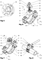
- the Figures 1-4 show a first variant of a ground terminal 1.
- the FIG. 5 shows a variant of an active compound.
- the Figures 6-7 show a second and a third variant of a ground terminal 1.
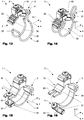
- the FIGS. 8 and 9 show a fourth variant of a ground terminal 1.
- Die FIGS. 10 to 12 show a variant of a clamping device 6.
- Die Figures 13-14 show a fifth variant of a ground terminal 1.
- the FIGS. 15-16 a sixth variant of a ground terminal 1.
- a ground terminal 1 comprises, as in the Figures 1-3 . 6-9 and 13-16 shown, usually a top 10, which has a circumferentially a receiving opening 7 at least partially curved and / or kinked body 11.
- a clamping base 12 forms in the variants shown an integral part of the upper part 10.
- a clamping plate 14 is operatively connected via a clamping screw 13 with the clamping base 12.
- the clamping base 12 has a threaded hole 27, which in the sectional view according to FIG. 7 is apparent.
- a spring 15 (coil spring) which is disposed between the clamping base 12 and the clamping plate 14, pushes the clamping plate 14 away from the clamping base 12.
- other types of springs may be used, such as bending springs.
- the clamping base 13 has a bore 16 which has a larger diameter than the spring 15 and which extends over a certain length along the clamping screw 13. The bore 16 serves to receive the spring 15 when the clamping plate 14 rests on the clamping base 12. The arrangement is best in FIG.
- the clamping base 13 has in the embodiment shown two at an angle of 90 ° to each other aligned notches 17, which serve for better positioning of the grounding line 5 when clamping.
- the clamping plate 14 has a central part 24, which has a bore 25 for the clamping screw 13. Furthermore, the clamping plate 13 comprises a support element 18, which can simultaneously serve as anti-rotation.
- the support member 18 is arranged at a right angle to the central part and extends in the mounted state parallel to a side surface 19 of the clamping base 12.
- the side surface 19 serves as a stop for the support element 18.
- the interaction of the support element 18 and the side surface 19 can be prevented be that the clamping plate 14 tilts when connecting the grounding line 5 in an inadvertent manner to the rear and so the clamping is impaired.
- the clamping plate 14 also includes an obliquely downwardly projecting clamping fingers 26, which prevents the terminals of the grounding line 5 that this slips laterally from the clamping base 12.
- FIG. 10 illustrated initial state
- the support member 18 rests on the stopper 19, so that rotation of the clamping plate 14 about the axis of the clamping screw 13, relative to the clamping base 6 is prevented.
- the support element 18 acts as anti-rotation.
- the clamping plate 14 can be tilted relative to the clamping base 6.
- FIG. 11 the fit between the bore 25 and the clamping screw 13 disposed therein dimensioned so that the necessary for tipping game is guaranteed, as in FIG. 11 is illustrated.
- one of the force applied by the spring 15 opposite force must be exerted. After the clamping plate 14 is tilted enough, it can be rotated about the axis of the clamping screw 13 without the rotation of the support element 18 is blocked. After the clamping plate 14 has been rotated to the desired position, the tilting as in FIG. 12 shown terminated (indicated by the dashed arrow).
- the support member 18 By the force applied by the spring 15, the support member 18 is then pressed against a stop 19, which causes a defined alignment between the clamping plate 14 and the clamping base 6.
- the support element 18 also serves as a type of alignment element which ensures a defined alignment of the clamping plate 14 with the two notches 17 of the clamping base 12.
- the main body 11 of the upper part 10 of the ground terminal 1 generally has at least one contact surface 20, which in the assembled state for electrical contacting of a tube 4 (see. FIG. 8 ) serves. If necessary, the main body 10 can be configured deformable.
- the earthing terminal 1 comprises, in addition to the upper part 10 mentioned above, a bow-shaped lower part 30 which, in the embodiments shown, consists of a sheet-metal strip (cf. Figures 1-9 ), a wire (cf. Figures 13-14 ) or by injection molding or extrusion of plastic or metal is made (see. FIGS. 15-16 ). Together with the upper part 10, the lower part 30 encloses a receiving space for a cylindrical body, such as a pipe or a rod or the like. By tightening the operative connection means, the upper part 10 and the lower part 30 can be fixed on the cylindrical body shown.
- the base 30 is less rigid in the circumferential direction as compared to the top 10, i. it has a greater flexibility in comparison to the upper part 10, such that when it is fitted around a cylindrical counter-body 4, such as e.g. the tube 4, in the circumferential direction stronger deformed compared to the upper part 10 as the thus operatively connected upper part 10th
- the lower part 30 has two straps 39 spaced apart from one another, which rest when the active connecting means 2, 3 are tightened around the counterbody and provide a secure hold. If necessary, the two straps 39 can also be operatively connected by one or more transverse webs.
- the upper part 10 and the lower part 30 are operatively connected to each other via a first and a second operative connection means 2, 3.
- the operative connection means 2, 3 may have different configurations depending on the field of application.
- a first operative connection means 2 is designed as a hook connection.
- one or more hooks 22 are formed on the upper part 10.
- At least one loop-shaped counterpart 34 which has one or more holding rungs 35, is formed on the lower part 30. This can be hung on the hook 22 during assembly.
- the Lower part 30 may have a chamfered end portion 36, which facilitates the mounting of the two parts during assembly.
- the opposite second operative connection means 3 is designed as a screw connection.
- a clamping screw 31 is mounted on the upper part 10 in a formed as a hole or thread 21 abutment and on the lower part 30 in an operatively connected with this nut 33.
- the second operative connection means 3 advantageously offers sufficient freedom that the hook connection of the first operative connection means 2 between the upper part 10 and the lower part 30 can be easily released or suspended.
- This relative displaceability is increased in particular by a hole 21 designed as an elongated hole, which enables a displacement and tilting of the clamping screw 31 relative to the upper part 10 during assembly.
- FIG. 4 In detail, an advantageous mounting of a nut 33 on a lower part 30.
- a square nut 33 is clamped between retaining tabs 38 and beads 32 in the variant shown that relative displacements and rotations between the square nut 33 and the rest of the lower part 30 are largely locked.
- Such storage can be made particularly simple and inexpensive, since no additional joining agents are necessary.
- Other fixings are possible.
- FIG. 5 shows another variant for supporting a clamping screw 31 in the lower part 30, in which a nut 33 welded to the lower part 30, or is pressed.
- a nut can also be glued or threaded directly be formed on the lower part 30. Combinations of different joining methods or means are also possible.
- the upper part 10 and the lower part 30 are mechanically connected to each other via first and a second formed as a screw connection active connection means 2, 3.
- one side of the upper part 10 is provided with a slot 22 and the other side with a longitudinal opening 23, which serves as a one-sided aligned passage opening.
- the ground terminal 1 can be mounted on a device, without having to be completely solved for one of the two screw 2, 3.
- FIGS. 8 and 9 show on pipes 4 with different diameters mounted grounding terminals 1, wherein in each case a grounding line 5 in transverse ( FIG. 8 ), or in longitudinal circuit ( FIG. 9 ) connected. As also shown, with the clamping device 12 according to the invention, grounding lines 5 with different diameters can be contacted electrically well.
- the grounding terminals 1 each have a plurality of transverse webs 35, whereby the same embodiment can be used for connection to pipes 4 of very different diameters.
- FIGS. 13 and 14 show a variant of a ground terminal 1 according to the present invention, in which the lower part 30 is formed in the manner of a wire bracket. On the upper part 10 more than one type of saw teeth formed hooks 22 are arranged, in which the transverse web of the lower part 30 -. suitable for the diameter of the relocating pipe - can be hung as in FIG. 14 will be shown.
- FIGS. 15 and 16 show a variant of a ground terminal 1 according to the present invention, in which the lower part 30 has been produced by means of an extrusion process and is shaped so that it can be hooked on one side at a corresponding end of the upper part 2.
- the upper part 10 comprises a longitudinal opening 23 which is formed as a one-sided aligned passage opening into which the clamping screw 31 can be switched on or off (indicated by the dashed arrow in FIG FIG. 16 ).
- the clamping screw 31 is mounted in a nut 33. This has in the embodiment shown on a U-shape, which can at least partially surround the lower part 30.
- the lower part 30 has an elongated opening in which the clamping screw 31 is mounted. Thereby, the clamping screw 31 can be angled relative to the lower part 30, which facilitates hanging in the longitudinal opening 23.
Landscapes
- Clamps And Clips (AREA)
- Supports For Pipes And Cables (AREA)
- Elimination Of Static Electricity (AREA)
Claims (11)
- Borne de terre (1) comportant
une partie supérieure (10) comportant un corps de base (11) et un dispositif de serrage (6) pour au moins une ligne de mise à la terre (5) ainsi que
une partie inférieure (30), laquelle peut être liée activement avec la partie supérieure (10) par l'intermédiaire d'un premier et d'un second moyen de liaison active (2, 3), la partie supérieure (10) et la partie inférieure (30) entourant en état de liaison active une ouverture de réception, caractérisée en ce que
la partie inférieure (30), en direction circonférentielle, est formée de manière moins rigide par rapport à la partie supérieure (10), de sorte qu'elle se déforme plus que la partie supérieure (30) lors de la pose autour d'un contre-corps (4) cylindrique en fonction de son diamètre, le premier moyen de liaison active (2) étant agencé en tant que liaison à crochet, la partie supérieure (10) comprenant au moins un crochet (22) et la partie inférieure (30) comportant au moins une contre-pièce en forme d'oeillets. - Borne de terre (1) selon l'une des revendications précédentes, caractérisée en ce que la partie supérieure (10) présente un corps de base (11) courbé et/ou plié, lequel forme une partie de l'ouverture de réception.
- Borne de terre (1) selon l'une des revendications précédentes, caractérisée en ce que la partie inférieure (30) est formée en plaque métallique et/ou en fil et/ou en plastique.
- Borne de terre (1) selon l'une des revendications précédentes, caractérisée en ce que la partie inférieure (30) comprend deux sangles (39) écartées l'une de l'autre.
- Borne de terre (1) selon l'une des revendications précédentes, caractérisée en ce que la partie supérieure (10) est constituée de laiton et/ou de bronze et/ou d'aluminium.
- Borne de terre (1) selon l'une des revendications précédentes, caractérisée en ce que la partie supérieure (10) présente au moins une surface de contact (20) pour mettre en contact le contre-corps (4).
- Borne de terre (1) selon l'une des revendications précédentes, caractérisée en ce que le corps de base (11) est fabriqué dans un procédé d'extrusion et/ou un procédé de moulage.
- Borne de terre (1) selon l'une des revendications précédentes, caractérisée en ce que la borne de terre comprend un dispositif de pince (6), le dispositif de serrage (6) présentant un socle de serrage (12) et une plaque de serrage (14) fixée au socle de serrage (12) à l'aide d'une vis de serrage (13).
- Borne de terre (1) selon la revendication 8, caractérisée en ce que la plaque de serrage (14) comprend un élément de support (18), lequel, en état monté, interagit avec une butée (19) du socle de serrage (12), de sorte qu'un basculement de la plaque de serrage (14) par rapport au socle de pince (12) est empêché.
- Borne de terre (1) selon la revendication 8 ou 9, caractérisée en ce que la plaque de serrage (14) peut tourner autour de la vis de serrage (13) d'une première position à une seconde position, de sorte que les lignes de mise à la terre (5) peuvent être serrées dans au moins deux directions différentes.
- Borne de terre (1) selon l'une des revendications 8 à 10, caractérisée en ce que le dispositif de serrage (6) présente un ressort (15), lequel repousse la plaque de serrage (14) du socle de serrage (12).
Priority Applications (1)
| Application Number | Priority Date | Filing Date | Title |
|---|---|---|---|
| PL16165919T PL3096407T3 (pl) | 2015-05-20 | 2016-04-19 | Zacisk uziemiający |
Applications Claiming Priority (1)
| Application Number | Priority Date | Filing Date | Title |
|---|---|---|---|
| CH00700/15A CH711109B1 (de) | 2015-05-20 | 2015-05-20 | Klemmvorrichtung für eine Erdungsklemme und Erdungsklemme. |
Publications (2)
| Publication Number | Publication Date |
|---|---|
| EP3096407A1 EP3096407A1 (fr) | 2016-11-23 |
| EP3096407B1 true EP3096407B1 (fr) | 2018-06-06 |
Family
ID=56026641
Family Applications (1)
| Application Number | Title | Priority Date | Filing Date |
|---|---|---|---|
| EP16165919.8A Active EP3096407B1 (fr) | 2015-05-20 | 2016-04-19 | Borne de mise a la terre |
Country Status (4)
| Country | Link |
|---|---|
| EP (1) | EP3096407B1 (fr) |
| CH (1) | CH711109B1 (fr) |
| DE (1) | DE202016008620U1 (fr) |
| PL (1) | PL3096407T3 (fr) |
Families Citing this family (7)
| Publication number | Priority date | Publication date | Assignee | Title |
|---|---|---|---|---|
| CN106848645B (zh) * | 2017-04-19 | 2023-02-28 | 广州番禺电缆集团有限公司 | 一种销接式电表接线夹 |
| CN109449618B (zh) * | 2018-11-07 | 2023-10-20 | 云南电网有限责任公司曲靖供电局 | 接地线组件 |
| CN109616783B (zh) * | 2019-01-22 | 2023-08-29 | 天津市管道工程集团有限公司 | 一种钢管接地线机构 |
| US11649910B2 (en) | 2020-03-06 | 2023-05-16 | Erico International Corporation | Systems and methods for a clamp |
| CN112531361A (zh) * | 2020-10-23 | 2021-03-19 | 广西电网有限责任公司北海供电局 | 一种新型圆管母线接地线挂接装置 |
| CN112750650B (zh) * | 2021-01-07 | 2022-11-11 | 余姚市超力电力电器有限公司 | 一种户外隔离开关的接地装置 |
| CN114322574B (zh) * | 2021-12-22 | 2023-12-12 | 芜湖福记恒机械有限公司 | 一种闪速炉中的异形铜水套及其浇铸成型工艺 |
Citations (2)
| Publication number | Priority date | Publication date | Assignee | Title |
|---|---|---|---|---|
| DE7638349U1 (de) * | 1976-12-08 | 1977-03-31 | Fa. Herman Kleinhuis, 5880 Luedenscheid | Erdungsrohrschelle |
| EP2555331A1 (fr) * | 2011-08-04 | 2013-02-06 | Agro Ag | Borne de mise à la terre |
Family Cites Families (5)
| Publication number | Priority date | Publication date | Assignee | Title |
|---|---|---|---|---|
| US2533897A (en) * | 1946-05-10 | 1950-12-12 | Morris D Reddock | Ground clamp |
| US5281761A (en) | 1992-02-25 | 1994-01-25 | Burndy Corporation | Grounding pipe/water pipe with compression connectors |
| DE50203970D1 (de) | 2002-09-05 | 2005-09-22 | Agro Ag Hunzenschwil | Erdleitungsbride |
| US7780461B1 (en) | 2009-03-03 | 2010-08-24 | Mike Vernica | Midpoint cable electrical ground clamp |
| US8449308B2 (en) * | 2010-10-07 | 2013-05-28 | Bridgeport Fittings, Inc. | Electric ground clamp with pivoted jaws and single attached adjusting bolt and terminal block |
-
2015
- 2015-05-20 CH CH00700/15A patent/CH711109B1/de unknown
-
2016
- 2016-04-19 DE DE202016008620.1U patent/DE202016008620U1/de not_active Expired - Lifetime
- 2016-04-19 PL PL16165919T patent/PL3096407T3/pl unknown
- 2016-04-19 EP EP16165919.8A patent/EP3096407B1/fr active Active
Patent Citations (2)
| Publication number | Priority date | Publication date | Assignee | Title |
|---|---|---|---|---|
| DE7638349U1 (de) * | 1976-12-08 | 1977-03-31 | Fa. Herman Kleinhuis, 5880 Luedenscheid | Erdungsrohrschelle |
| EP2555331A1 (fr) * | 2011-08-04 | 2013-02-06 | Agro Ag | Borne de mise à la terre |
Also Published As
| Publication number | Publication date |
|---|---|
| DE202016008620U1 (de) | 2018-09-13 |
| PL3096407T3 (pl) | 2019-02-28 |
| EP3096407A1 (fr) | 2016-11-23 |
| CH711109A2 (de) | 2016-11-30 |
| CH711109B1 (de) | 2020-03-13 |
Similar Documents
| Publication | Publication Date | Title |
|---|---|---|
| EP3096407B1 (fr) | Borne de mise a la terre | |
| DE69815744T2 (de) | Rotierende Erdungskupplung zum äusseren Erden von Gehäusen | |
| DE4214508C2 (de) | Anordnung zur Masseanbindung an eine innere Blitzschutzanlage | |
| DE4142642C2 (de) | Rohr/Draht-Klemmanordnung | |
| WO2012072318A1 (fr) | Dispositif de fixation pour la fixation d'un câble | |
| DE202012102394U1 (de) | Befestigungselement | |
| DE202015102037U1 (de) | Konstruktionsklemme | |
| DE102011050212A1 (de) | Kompensationsklemme | |
| DE102011108123A1 (de) | Kabelanschlussbauteil sowie Kabelanschlusseinrichtung und Kabelverbindungseinrichtung mit einem Kabelanschlussbauteil | |
| DE202013104621U1 (de) | Batterieklemme | |
| EP3539183B1 (fr) | Élément de contact à raccordement par serrage pour conducteur multibrin | |
| DE202018104252U1 (de) | Blitzschutz- und Erdungsklemme | |
| EP2037164B1 (fr) | Collier de serrage | |
| DE3044007A1 (de) | Verbindungsvorrichtung zur verankerung und befestigung von leitungen, heizkoerpern von schwerkraftwarmwasserheizungsanlagen u.dgl. an mauerwerken, wie waenden, decken u.dgl. | |
| DE3909548C2 (fr) | ||
| DE102007052935B4 (de) | Steckelement zum mechanischen Fixieren von Rohren an einem Gehäuse sowie zum Bereitstellen eines Anschlusses für die Kontaktierung eines Schutzleiters | |
| DE102010017440A1 (de) | Kabeldurchführung für einen Durchbruch in einer Wandung | |
| EP3602697B1 (fr) | Cadre de connecteur avec contact pe | |
| DE29806397U1 (de) | Kabelschuh | |
| DE102017129345A1 (de) | Erdungsklammer für metallische Rohrleitungselemente, und Rohrleitungssystem mit selbiger | |
| DE102015120002A1 (de) | Verbindungsvorrichtung und Verbindungsverfahren | |
| EP3084860B1 (fr) | Borne de batterie | |
| DE102008049377B4 (de) | Massekontaktbaugruppe zur Anordnung an einem Massebolzen | |
| DE102009040222A1 (de) | Batteriepolklemme mit Feder | |
| EP4687222A1 (fr) | Borne de conducteur de protection contre la foudre |
Legal Events
| Date | Code | Title | Description |
|---|---|---|---|
| REG | Reference to a national code |
Ref country code: DE Ref legal event code: R138 Ref document number: 202016008620 Country of ref document: DE Free format text: GERMAN DOCUMENT NUMBER IS 502016001141 |
|
| PUAI | Public reference made under article 153(3) epc to a published international application that has entered the european phase |
Free format text: ORIGINAL CODE: 0009012 |
|
| AK | Designated contracting states |
Kind code of ref document: A1 Designated state(s): AL AT BE BG CH CY CZ DE DK EE ES FI FR GB GR HR HU IE IS IT LI LT LU LV MC MK MT NL NO PL PT RO RS SE SI SK SM TR |
|
| AX | Request for extension of the european patent |
Extension state: BA ME |
|
| STAA | Information on the status of an ep patent application or granted ep patent |
Free format text: STATUS: REQUEST FOR EXAMINATION WAS MADE |
|
| 17P | Request for examination filed |
Effective date: 20170519 |
|
| RBV | Designated contracting states (corrected) |
Designated state(s): AL AT BE BG CH CY CZ DE DK EE ES FI FR GB GR HR HU IE IS IT LI LT LU LV MC MK MT NL NO PL PT RO RS SE SI SK SM TR |
|
| STAA | Information on the status of an ep patent application or granted ep patent |
Free format text: STATUS: EXAMINATION IS IN PROGRESS |
|
| 17Q | First examination report despatched |
Effective date: 20170731 |
|
| GRAP | Despatch of communication of intention to grant a patent |
Free format text: ORIGINAL CODE: EPIDOSNIGR1 |
|
| STAA | Information on the status of an ep patent application or granted ep patent |
Free format text: STATUS: GRANT OF PATENT IS INTENDED |
|
| INTG | Intention to grant announced |
Effective date: 20171211 |
|
| GRAS | Grant fee paid |
Free format text: ORIGINAL CODE: EPIDOSNIGR3 |
|
| GRAA | (expected) grant |
Free format text: ORIGINAL CODE: 0009210 |
|
| STAA | Information on the status of an ep patent application or granted ep patent |
Free format text: STATUS: THE PATENT HAS BEEN GRANTED |
|
| AK | Designated contracting states |
Kind code of ref document: B1 Designated state(s): AL AT BE BG CH CY CZ DE DK EE ES FI FR GB GR HR HU IE IS IT LI LT LU LV MC MK MT NL NO PL PT RO RS SE SI SK SM TR |
|
| REG | Reference to a national code |
Ref country code: GB Ref legal event code: FG4D Free format text: NOT ENGLISH |
|
| REG | Reference to a national code |
Ref country code: CH Ref legal event code: EP Ref country code: AT Ref legal event code: REF Ref document number: 1007070 Country of ref document: AT Kind code of ref document: T Effective date: 20180615 |
|
| REG | Reference to a national code |
Ref country code: IE Ref legal event code: FG4D Free format text: LANGUAGE OF EP DOCUMENT: GERMAN |
|
| REG | Reference to a national code |
Ref country code: DE Ref legal event code: R096 Ref document number: 502016001141 Country of ref document: DE |
|
| REG | Reference to a national code |
Ref country code: CH Ref legal event code: NV Representative=s name: RENTSCH PARTNER AG, CH |
|
| REG | Reference to a national code |
Ref country code: NL Ref legal event code: FP |
|
| REG | Reference to a national code |
Ref country code: LT Ref legal event code: MG4D |
|
| PG25 | Lapsed in a contracting state [announced via postgrant information from national office to epo] |
Ref country code: CY Free format text: LAPSE BECAUSE OF FAILURE TO SUBMIT A TRANSLATION OF THE DESCRIPTION OR TO PAY THE FEE WITHIN THE PRESCRIBED TIME-LIMIT Effective date: 20180606 Ref country code: LT Free format text: LAPSE BECAUSE OF FAILURE TO SUBMIT A TRANSLATION OF THE DESCRIPTION OR TO PAY THE FEE WITHIN THE PRESCRIBED TIME-LIMIT Effective date: 20180606 Ref country code: BG Free format text: LAPSE BECAUSE OF FAILURE TO SUBMIT A TRANSLATION OF THE DESCRIPTION OR TO PAY THE FEE WITHIN THE PRESCRIBED TIME-LIMIT Effective date: 20180906 Ref country code: ES Free format text: LAPSE BECAUSE OF FAILURE TO SUBMIT A TRANSLATION OF THE DESCRIPTION OR TO PAY THE FEE WITHIN THE PRESCRIBED TIME-LIMIT Effective date: 20180606 Ref country code: SE Free format text: LAPSE BECAUSE OF FAILURE TO SUBMIT A TRANSLATION OF THE DESCRIPTION OR TO PAY THE FEE WITHIN THE PRESCRIBED TIME-LIMIT Effective date: 20180606 Ref country code: FI Free format text: LAPSE BECAUSE OF FAILURE TO SUBMIT A TRANSLATION OF THE DESCRIPTION OR TO PAY THE FEE WITHIN THE PRESCRIBED TIME-LIMIT Effective date: 20180606 Ref country code: NO Free format text: LAPSE BECAUSE OF FAILURE TO SUBMIT A TRANSLATION OF THE DESCRIPTION OR TO PAY THE FEE WITHIN THE PRESCRIBED TIME-LIMIT Effective date: 20180906 |
|
| PG25 | Lapsed in a contracting state [announced via postgrant information from national office to epo] |
Ref country code: LV Free format text: LAPSE BECAUSE OF FAILURE TO SUBMIT A TRANSLATION OF THE DESCRIPTION OR TO PAY THE FEE WITHIN THE PRESCRIBED TIME-LIMIT Effective date: 20180606 Ref country code: RS Free format text: LAPSE BECAUSE OF FAILURE TO SUBMIT A TRANSLATION OF THE DESCRIPTION OR TO PAY THE FEE WITHIN THE PRESCRIBED TIME-LIMIT Effective date: 20180606 Ref country code: GR Free format text: LAPSE BECAUSE OF FAILURE TO SUBMIT A TRANSLATION OF THE DESCRIPTION OR TO PAY THE FEE WITHIN THE PRESCRIBED TIME-LIMIT Effective date: 20180907 Ref country code: HR Free format text: LAPSE BECAUSE OF FAILURE TO SUBMIT A TRANSLATION OF THE DESCRIPTION OR TO PAY THE FEE WITHIN THE PRESCRIBED TIME-LIMIT Effective date: 20180606 |
|
| REG | Reference to a national code |
Ref country code: SK Ref legal event code: T3 Ref document number: E 28567 Country of ref document: SK |
|
| PG25 | Lapsed in a contracting state [announced via postgrant information from national office to epo] |
Ref country code: RO Free format text: LAPSE BECAUSE OF FAILURE TO SUBMIT A TRANSLATION OF THE DESCRIPTION OR TO PAY THE FEE WITHIN THE PRESCRIBED TIME-LIMIT Effective date: 20180606 Ref country code: IS Free format text: LAPSE BECAUSE OF FAILURE TO SUBMIT A TRANSLATION OF THE DESCRIPTION OR TO PAY THE FEE WITHIN THE PRESCRIBED TIME-LIMIT Effective date: 20181006 Ref country code: EE Free format text: LAPSE BECAUSE OF FAILURE TO SUBMIT A TRANSLATION OF THE DESCRIPTION OR TO PAY THE FEE WITHIN THE PRESCRIBED TIME-LIMIT Effective date: 20180606 |
|
| PG25 | Lapsed in a contracting state [announced via postgrant information from national office to epo] |
Ref country code: SM Free format text: LAPSE BECAUSE OF FAILURE TO SUBMIT A TRANSLATION OF THE DESCRIPTION OR TO PAY THE FEE WITHIN THE PRESCRIBED TIME-LIMIT Effective date: 20180606 |
|
| REG | Reference to a national code |
Ref country code: DE Ref legal event code: R097 Ref document number: 502016001141 Country of ref document: DE |
|
| PLBE | No opposition filed within time limit |
Free format text: ORIGINAL CODE: 0009261 |
|
| STAA | Information on the status of an ep patent application or granted ep patent |
Free format text: STATUS: NO OPPOSITION FILED WITHIN TIME LIMIT |
|
| 26N | No opposition filed |
Effective date: 20190307 |
|
| PG25 | Lapsed in a contracting state [announced via postgrant information from national office to epo] |
Ref country code: SI Free format text: LAPSE BECAUSE OF FAILURE TO SUBMIT A TRANSLATION OF THE DESCRIPTION OR TO PAY THE FEE WITHIN THE PRESCRIBED TIME-LIMIT Effective date: 20180606 Ref country code: DK Free format text: LAPSE BECAUSE OF FAILURE TO SUBMIT A TRANSLATION OF THE DESCRIPTION OR TO PAY THE FEE WITHIN THE PRESCRIBED TIME-LIMIT Effective date: 20180606 |
|
| PG25 | Lapsed in a contracting state [announced via postgrant information from national office to epo] |
Ref country code: AL Free format text: LAPSE BECAUSE OF FAILURE TO SUBMIT A TRANSLATION OF THE DESCRIPTION OR TO PAY THE FEE WITHIN THE PRESCRIBED TIME-LIMIT Effective date: 20180606 |
|
| PG25 | Lapsed in a contracting state [announced via postgrant information from national office to epo] |
Ref country code: MC Free format text: LAPSE BECAUSE OF FAILURE TO SUBMIT A TRANSLATION OF THE DESCRIPTION OR TO PAY THE FEE WITHIN THE PRESCRIBED TIME-LIMIT Effective date: 20180606 |
|
| PG25 | Lapsed in a contracting state [announced via postgrant information from national office to epo] |
Ref country code: TR Free format text: LAPSE BECAUSE OF FAILURE TO SUBMIT A TRANSLATION OF THE DESCRIPTION OR TO PAY THE FEE WITHIN THE PRESCRIBED TIME-LIMIT Effective date: 20180606 |
|
| PG25 | Lapsed in a contracting state [announced via postgrant information from national office to epo] |
Ref country code: IE Free format text: LAPSE BECAUSE OF NON-PAYMENT OF DUE FEES Effective date: 20190419 |
|
| PG25 | Lapsed in a contracting state [announced via postgrant information from national office to epo] |
Ref country code: PT Free format text: LAPSE BECAUSE OF FAILURE TO SUBMIT A TRANSLATION OF THE DESCRIPTION OR TO PAY THE FEE WITHIN THE PRESCRIBED TIME-LIMIT Effective date: 20181008 |
|
| GBPC | Gb: european patent ceased through non-payment of renewal fee |
Effective date: 20200419 |
|
| PG25 | Lapsed in a contracting state [announced via postgrant information from national office to epo] |
Ref country code: GB Free format text: LAPSE BECAUSE OF NON-PAYMENT OF DUE FEES Effective date: 20200419 |
|
| PGFP | Annual fee paid to national office [announced via postgrant information from national office to epo] |
Ref country code: LU Payment date: 20210420 Year of fee payment: 6 |
|
| PG25 | Lapsed in a contracting state [announced via postgrant information from national office to epo] |
Ref country code: HU Free format text: LAPSE BECAUSE OF FAILURE TO SUBMIT A TRANSLATION OF THE DESCRIPTION OR TO PAY THE FEE WITHIN THE PRESCRIBED TIME-LIMIT; INVALID AB INITIO Effective date: 20160419 Ref country code: MT Free format text: LAPSE BECAUSE OF FAILURE TO SUBMIT A TRANSLATION OF THE DESCRIPTION OR TO PAY THE FEE WITHIN THE PRESCRIBED TIME-LIMIT Effective date: 20180606 |
|
| PGFP | Annual fee paid to national office [announced via postgrant information from national office to epo] |
Ref country code: IT Payment date: 20210427 Year of fee payment: 6 Ref country code: CZ Payment date: 20210419 Year of fee payment: 6 Ref country code: FR Payment date: 20210423 Year of fee payment: 6 Ref country code: SK Payment date: 20210414 Year of fee payment: 6 |
|
| PGFP | Annual fee paid to national office [announced via postgrant information from national office to epo] |
Ref country code: PL Payment date: 20210408 Year of fee payment: 6 |
|
| PG25 | Lapsed in a contracting state [announced via postgrant information from national office to epo] |
Ref country code: MK Free format text: LAPSE BECAUSE OF FAILURE TO SUBMIT A TRANSLATION OF THE DESCRIPTION OR TO PAY THE FEE WITHIN THE PRESCRIBED TIME-LIMIT Effective date: 20180606 |
|
| REG | Reference to a national code |
Ref country code: SK Ref legal event code: MM4A Ref document number: E 28567 Country of ref document: SK Effective date: 20220419 |
|
| PG25 | Lapsed in a contracting state [announced via postgrant information from national office to epo] |
Ref country code: SK Free format text: LAPSE BECAUSE OF NON-PAYMENT OF DUE FEES Effective date: 20220419 Ref country code: LU Free format text: LAPSE BECAUSE OF NON-PAYMENT OF DUE FEES Effective date: 20220419 Ref country code: FR Free format text: LAPSE BECAUSE OF NON-PAYMENT OF DUE FEES Effective date: 20220430 Ref country code: CZ Free format text: LAPSE BECAUSE OF NON-PAYMENT OF DUE FEES Effective date: 20220419 |
|
| PG25 | Lapsed in a contracting state [announced via postgrant information from national office to epo] |
Ref country code: IT Free format text: LAPSE BECAUSE OF NON-PAYMENT OF DUE FEES Effective date: 20220419 |
|
| P01 | Opt-out of the competence of the unified patent court (upc) registered |
Effective date: 20230513 |
|
| PG25 | Lapsed in a contracting state [announced via postgrant information from national office to epo] |
Ref country code: PL Free format text: LAPSE BECAUSE OF NON-PAYMENT OF DUE FEES Effective date: 20220419 |
|
| PGFP | Annual fee paid to national office [announced via postgrant information from national office to epo] |
Ref country code: NL Payment date: 20250418 Year of fee payment: 10 |
|
| PGFP | Annual fee paid to national office [announced via postgrant information from national office to epo] |
Ref country code: DE Payment date: 20250422 Year of fee payment: 10 |
|
| PGFP | Annual fee paid to national office [announced via postgrant information from national office to epo] |
Ref country code: BE Payment date: 20250418 Year of fee payment: 10 |
|
| PGFP | Annual fee paid to national office [announced via postgrant information from national office to epo] |
Ref country code: CH Payment date: 20250501 Year of fee payment: 10 |
|
| PGFP | Annual fee paid to national office [announced via postgrant information from national office to epo] |
Ref country code: AT Payment date: 20250423 Year of fee payment: 10 |
|
| REG | Reference to a national code |
Ref country code: DE Ref legal event code: R082 Ref document number: 502016001141 Country of ref document: DE Representative=s name: RENTSCH LEGAL PARTNERS GMBH, DE |