EP3096457B1 - Détecteur de proximité - Google Patents
Détecteur de proximité Download PDFInfo
- Publication number
- EP3096457B1 EP3096457B1 EP16170295.6A EP16170295A EP3096457B1 EP 3096457 B1 EP3096457 B1 EP 3096457B1 EP 16170295 A EP16170295 A EP 16170295A EP 3096457 B1 EP3096457 B1 EP 3096457B1
- Authority
- EP
- European Patent Office
- Prior art keywords
- tank circuit
- active
- passive
- resonant tank
- circuit
- Prior art date
- Legal status (The legal status is an assumption and is not a legal conclusion. Google has not performed a legal analysis and makes no representation as to the accuracy of the status listed.)
- Active
Links
Images

Classifications
-
- G—PHYSICS
- G01—MEASURING; TESTING
- G01D—MEASURING NOT SPECIALLY ADAPTED FOR A SPECIFIC VARIABLE; ARRANGEMENTS FOR MEASURING TWO OR MORE VARIABLES NOT COVERED IN A SINGLE OTHER SUBCLASS; TARIFF METERING APPARATUS; MEASURING OR TESTING NOT OTHERWISE PROVIDED FOR
- G01D5/00—Mechanical means for transferring the output of a sensing member; Means for converting the output of a sensing member to another variable where the form or nature of the sensing member does not constrain the means for converting; Transducers not specially adapted for a specific variable
- G01D5/12—Mechanical means for transferring the output of a sensing member; Means for converting the output of a sensing member to another variable where the form or nature of the sensing member does not constrain the means for converting; Transducers not specially adapted for a specific variable using electric or magnetic means
- G01D5/14—Mechanical means for transferring the output of a sensing member; Means for converting the output of a sensing member to another variable where the form or nature of the sensing member does not constrain the means for converting; Transducers not specially adapted for a specific variable using electric or magnetic means influencing the magnitude of a current or voltage
- G01D5/20—Mechanical means for transferring the output of a sensing member; Means for converting the output of a sensing member to another variable where the form or nature of the sensing member does not constrain the means for converting; Transducers not specially adapted for a specific variable using electric or magnetic means influencing the magnitude of a current or voltage by varying inductance, e.g. by a movable armature
-
- G—PHYSICS
- G01—MEASURING; TESTING
- G01B—MEASURING LENGTH, THICKNESS OR SIMILAR LINEAR DIMENSIONS; MEASURING ANGLES; MEASURING AREAS; MEASURING IRREGULARITIES OF SURFACES OR CONTOURS
- G01B7/00—Measuring arrangements characterised by the use of electric or magnetic techniques
- G01B7/14—Measuring arrangements characterised by the use of electric or magnetic techniques for measuring distance or clearance between spaced objects or spaced apertures
-
- G—PHYSICS
- G01—MEASURING; TESTING
- G01B—MEASURING LENGTH, THICKNESS OR SIMILAR LINEAR DIMENSIONS; MEASURING ANGLES; MEASURING AREAS; MEASURING IRREGULARITIES OF SURFACES OR CONTOURS
- G01B7/00—Measuring arrangements characterised by the use of electric or magnetic techniques
-
- H—ELECTRICITY
- H03—ELECTRONIC CIRCUITRY
- H03K—PULSE TECHNIQUE
- H03K17/00—Electronic switching or gating, i.e. not by contact-making and –breaking
- H03K17/94—Electronic switching or gating, i.e. not by contact-making and –breaking characterised by the way in which the control signals are generated
- H03K17/945—Proximity switches
- H03K17/95—Proximity switches using a magnetic detector
- H03K17/952—Proximity switches using a magnetic detector using inductive coils
- H03K17/9537—Proximity switches using a magnetic detector using inductive coils in a resonant circuit
- H03K17/954—Proximity switches using a magnetic detector using inductive coils in a resonant circuit controlled by an oscillatory signal
Definitions
- Proximity sensing devices are devices that produce an output based upon a distance between two or more sensors or objects.
- Proximity sensors typically contain electrical circuits having an electrical, mechanical, or optical distance sensing portion.
- Electromechanical sensors are often used to establish contact between two objects, such as an end switch, and electrical sensors are frequently used when a distance measurement is desired.
- Electrical proximity sensors commonly include inductance sensors, which rely on unique electrical properties of inductance circuits to detect the proximity of a target object.
- Proximity sensors are prevalent in several industries, such as process management, automotive, and aviation. Their applications span a large range from traffic control to linkage actuation control. For example, proximity sensing devices are an integral and indispensable component of a modern aircraft. Knowledge that a moving surface has reached a particular location in its travel can promote proper and safe operation of various aircraft systems.
- US 2005/007239 A1 relates to a remote monitoring system.
- a proximity sensor is provided as claimed in claim 1.
- a proximity sensor system is provided as claimed in claim 7..
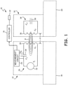
- FIG. 1 is a schematic view of proximity sensor system 10, which includes active sensor 12, passive target 14, controller 16, first structure 18, second structure 20, and system components 22.
- Active sensor 12 includes measurement circuit 24 and active resonant tank circuit 26.
- Active resonant tank circuit 26 includes capacitor 28, inductor 30, and excitation source 32.
- Passive target 14 includes passive resonant tank circuit 34, which includes inductor 36 and capacitor 38. Also shown in FIG. 1 are distance d, capacitance C 1 , capacitance C 2 , inductance L 1 , Inductance L 2 , drive signal voltage V s , sensor output voltage V o , and magnetic field B.
- Active sensor 12 is physically connected to first structure 18 by welding, riveting, screwing, co-molding, or another fastening means. Also, active sensor 12 can be enclosed by a housing (not shown) which can then be attached to first structure 18. Similarly, passive target 14 is physically connected to second structure 20 by welding, riveting, screwing, co-molding, or another fastening means. Also, passive target 14 can be enclosed by a housing (not shown) which can then be attached to second structure 20. Active sensor 12 and passive target 14 are fixed to first structure 18 and second structure 20, respectively. However, active sensor 12 and passive target 14 can move relative to one another, as first structure 18 and second structure 20 can move with respect to each other. Distance d represents the physical distance between inductor 30 and inductor 36.
- inductor 30 is a component of active sensor 12, which is attached to first structure 18, distance d between inductors 30 and 36 can be easily correlated to other distances, such as a distance between active sensor 12 and passive target 14, and their respective components.
- first structure 18 and second structure 20 can be connected to each other but still free to move relative to each other, for example as parts of a linkage assembly.
- Measurement circuit 24 can be physically attached to first structure 18 by welding, riveting, screwing, co-molding, or another fastening means. Additionally, measurement 24 can be on a common printed circuit board with active sensor 12 or can otherwise be integrated into active sensor 12. For example, measurement circuit 24 and active resonant tank circuit 26 can be within a common housing within active sensor 12. Controller 16 can be mounted to first structure 18 or second structure 20; however, in many examples controller 16 can be mounted physically remotely from first structure 18 and second structure 20.
- Capacitor 28 of active resonant tank circuit 26 is electrically connected in series with inductor 30 and excitation source 32.
- Capacitor 28 has a capacitance C 1
- inductor 30 has an inductance L 1 .
- Excitation source 32 produces a drive signal voltage Vs.
- Capacitor 38 of passive resonant tank circuit 34 is connected with inductor 36 in parallel.
- Capacitor 38 has a capacitance C 2
- inductor 36 has an inductance L 2 .
- Capacitors 28 and 38 can be a ceramic capacitor, film capacitor, or any type of capacitor capable of storing electrical energy and having sufficient quality factor Q to operate effectively in a resonant circuit.
- Inductors 30 and 36 can be a ferromagnetic inductor, an air core inductor, or any other type of inductor having sufficient quality factor Q to operate effectively in a resonant circuit.
- Excitation source 32 can be an alternating current (AC) power supply for producing a current or excitation pulse.
- AC alternating current
- Active resonant tank circuit 26 and its components create an active series resonator circuit, also known as a tank circuit, resonant circuit, or tuned circuit.
- Passive resonant tank circuit 34 and its components create a passive parallel resonator circuit, also known as a tank circuit, resonant circuit, or tuned circuit.
- Measurement circuit 24 is connected to active resonant tank circuit 26 across capacitor 28. Measurement circuit 24 measures sensor output voltage V o . Measurement circuit 24 is also electrically connected to controller 16, which further electrically connects to system components 22.
- System components 22 can be any system component capable of being moved or articulated. For example, first structure 18 and second structure 20 could be system components 22.
- excitation source 32 sends a current to capacitor 28, which stores charge and ultimately discharges the current to inductor 30.
- Excitation source 32 provides continuous power to active resonant tank circuit 26 creating continuous oscillations of magnetic field B at the natural frequency of active resonant tank circuit 26, creating resonance.
- Passive resonant tank circuit 34 is tuned to the same or similar resonant frequency of active circuit 32, where the product of capacitor 28 and inductor 30 can be approximately equal to the product of capacitor 38 and inductor 36.
- passive resonant tank circuit 34 When passive resonant tank circuit 34 is within range of magnetic field B , passive resonant tank circuit 34 and active resonant tank circuit 26 become magnetically coupled. When coupled, magnetic field B will induce a current through inductor 36, which will flow in passive resonant tank circuit 34. In response to this current flow, Lenz's law dictates that inductor 36 will produce a magnetic field in a direction opposite of that created by inductor 30. The magnetic field response by inductor 36 is received by inductor 30 of active resonant tank circuit 26. The reflected load can create a coupled resonant frequency response ⁇ c1 , or an electrical response, in active resonant tank circuit 26.
- the electrical response in active resonant tank circuit 26 is detectible by measuring and analyzing the current through or the voltage across a component of active resonant tank circuit 26.
- measurement circuit 24 measures the voltage across capacitor 28 to observe coupled resonant frequency responses ⁇ c1 and ⁇ c 2 through active resonant tank circuit 26.
- measurement circuit 24 can measure the voltage across any component of active resonant tank circuit 26.
- Measurement circuit 24 can include an oscillator, demodulator, and other components to obtain an accurate measurement of coupled resonant frequency responses ⁇ c1 and ⁇ c 2 .
- a unique, easily detectible response can be observed through a measurement of coupled resonant frequency response ⁇ c1 ; however, for the response to be unique, easily detectible, and useful as a proximity sensor, some conditions can be met.
- the first condition is that a circuit quality factor Q is greater than 1 for both circuits, or: Q 1 > 1 and Q 2 > 1
- Q 1 is the quality factor of active resonant tank circuit 26 and Q 2 is the quality factor of passive resonant tank circuit 34.
- quality factors Q 1 and Q 2 are much greater than one (in many embodiments, at least one order of magnitude, i.e. ten times greater), or: Q 1 ⁇ 1 and Q 2 ⁇ 1
- R 1 is the resistance of active resonant tank circuit 26.
- the quality factor of passive resonant tank circuit 34 is given by the equation
- R 2 is the resistance of passive resonant tank circuit 34.
- R 1 and R 2 can be only the parasitic resistance of their respective circuit, because the circuit contains no added resistor component, as it is desired to maintain a high quality factor in each circuit.
- a second condition that can be met is that resonant frequencies or both circuits ⁇ R1 and of ⁇ R2 can be approximately equal.
- the resonant frequency for each circuit is determined by the equations:
- the third condition that can be met is that a coefficient of coupling k between active resonant tank circuit 26 and passive resonant tank circuit 34 can be greater than a critical coefficient of coupling k c between active resonant tank circuit 26 and passive resonant tank circuit 34.
- the coefficient of coupling k is the magnetic coupling coefficient between circuits, which ranges from zero to one, or 0 ⁇ k ⁇ 1, and is defined by
- M is the mutual inductance of inductors L 1 and L 2 or inductors 30 and 36.
- the mutual inductance M of inductors 30 and 36 correlates directly and varies with distance d.
- the coupled resonant frequency responses ⁇ c1 and ⁇ c2 of active resonant tank circuit 26 and the passive resonant tank circuit 34 can be determined by the equations
- the coupled resonant frequency responses ⁇ c1 and ⁇ c2 of active resonant tank circuit 26 and passive resonant tank circuit 34, respectively, are dependent only on the uncoupled resonant frequencies ⁇ R1 and ⁇ R2 , respectively, and the coefficient of coupling k between active resonant tank circuit 26 and passive resonant tank circuit 34. Because the uncoupled resonant frequency will be fixed by the inductance L and capacitance C of each circuit, the coupled resonant frequency responses ⁇ c1 and ⁇ c2 are primarily dependent on the coefficient of coupling k.
- the coupled resonant frequency response ⁇ c1 of active resonant tank circuit 26 is primarily dependent on the coefficient of coupling k between active resonant tank circuit 26 and passive resonant tank circuit 34.
- the coefficient of coupling k between active resonant tank circuit 26 and passive resonant tank circuit 34 is given by Equation 5 above, where M is the mutual inductance of inductors L 1 and L 2 or inductors 30 and 36.
- the mutual inductance M of inductors 30 and 36 is primarily dependent on distance d, the distance between inductors 30 and 36.
- the coefficient of coupling k is primarily dependent on distance d, and that the coupled resonant frequency responses ⁇ c1 and ⁇ c2 are then primarily dependent on distance d. Therefore, with active resonant tank circuit 26 and passive resonant tank circuit 34 meeting the exemplary conditions, the electrical response, or the coupled resonant frequency response ⁇ c1 in active resonant tank circuit 26 caused by an interaction with passive resonant tank circuit 34 becomes a function primarily dependent on distance d between inductors 30 and 36.
- the coupled resonant frequency response ⁇ c1 or electrical response can be measured by measurement circuit 24 and transformed into a measured distance output to be used by, for example, controller 16.
- active resonant tank circuit 26 and passive resonant tank circuit 34 to be used to sense proximity or distance.
- the electrical response can be correlated to the separation in distance d between active sensor 12 and passive target 14.
- Distance d represents the physical distance between inductor 30 and inductor 36. Because inductor is a component of active sensor 12 and inductor 36 is a component of first structure 18, distance d between inductors 30 and 36 can be easily correlated to other distances between active sensor 12 and first structure 18, and their respective components.
- the prior art includes proximity sensors that can include an active tank circuit of an active sensor and a ferromagnetic passive target. While a ferromagnetic target does produce an electrical response in the active circuit by affecting the magnetic field of the tank circuit's inductor, the application has some drawbacks. First, these sensors can have a small physical operating range, or struggle to operate over a large distance d . This imposes tight calibration requirements to allow the desired signal to be detected by the active sensor. Therefore, the electronic signature produced by this type of system can, in some examples, vary by only a few percent between a near condition (when the target is very close to the active sensor) and the far condition (when the target is relatively distant from the active sensor).
- the active sensor is designed to interact with ferromagnetic passive targets impacting the magnetic field of the active circuit
- the circuit is susceptible to ambient noise and interference. To account for such interference, can require a complicated design of the signal conditioning and measurement electronics interacting with the active portion of the sensor. This can increase the cost and complexity of the devices.
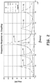
- FIG. 2 is a graph illustrating one embodiment of frequency response versus the coefficient of coupling k of active resonant tank circuit 26 and passive resonant tank circuit 34 FIG. 1 .
- Frequency ⁇ is displayed on the x-axis of the graph and magnitude Mag is displayed on the y-axis of the graph.
- magnitude Mag is displayed on the y-axis of the graph.
- Also displayed on the graph are four response curves, curve 40, curve 42, curve 44, and curve 46.
- Magnitude Mag has a range on the y-axis of 0 decibels (dB) to magnitude Mag of 140 dB, with intermediate markers along the y-axis denoting steps of 20 dB.
- Frequency ⁇ moves from the left to the right side of its axis, ranging from 4.4 x 10 5 Hertz (Hz) to 5.8 x 10 5 Hz at its maximum, with increments of 0.2 x 10 5 Hz denoted.
- curve 40 is a response curve where the coefficient of coupling k between active resonant tank circuit 26 and passive resonant tank circuit 34 is 0.001
- curve 42 is a response curve where the coefficient of coupling k between active resonant tank circuit 26 and passive resonant tank circuit 34 is 0.01
- curve 44 is a response curve where the coefficient between coupling k of active resonant tank circuit 26 and passive resonant tank circuit 34 is 0.1
- curve 46 is a response curve where the coefficient of coupling k between active resonant tank circuit 26 and passive resonant tank circuit 34 is 0.2. Detecting or observing these responses in active resonant tank circuit 26 can be performed using any standard technique.
- Curves 40, 42, 44, and 46 represent the signature of the electrical response signal in active resonant tank circuit 26 based on the coefficient of coupling k , showing how much of the signal is within each frequency.
- Curve 40 which represents a coefficient of coupling k of 0.001, has a single discernable resonant frequency signature having a single peak amplitude in the displayed range.
- Curve 40 displays a frequency response having a coefficient of coupling k of 0.001, which is so low that the coupled frequency responses ⁇ c1 and ⁇ c2 are nearly equal to resonant frequency ⁇ R1 of active resonant tank circuit 26. This is given by the equation: ⁇ c 1 ⁇ ⁇ c 2 ⁇ ⁇ R 1
- Curve 42 which represents a coefficient of coupling k of 0.01, depicts a curve showing a split frequency response.
- Curve 42 has a signature having coupled frequency responses ⁇ c1 and ⁇ c2 separated by 0.05 x 10 5 Hz as curve 42 has a split peak amplitude (or double hump curve), having a trough at the same frequency of the peak of curve 40.
- the coupled frequency response ⁇ c1 of curve 42 occurs at approximately 5.0 x 10 5 Hz and coupled frequency response ⁇ c2 occurs at approximately 5.05 x 10 5 Hz.
- Curve 44 which represents a coefficient of coupling k of 0.1, has a signature with coupled frequency responses ⁇ c1 and ⁇ c2 at approximately 4.8 x 10 5 Hz and 5.3 x 10 5 Hz.
- the separation in peaks of curve 44 is 0.5 x 10 5 Hz, which is significantly greater than the separation between peaks in curve 42, which is approximately 0.05 x 10 5 Hz.
- This resonant frequency response separation effect is even greater in curve 46, which has peaks at approximately 4.6 x 10 5 Hz and 5.65 x 10 5 Hz. Also, the magnitudes of the peaks in curve 46 differ.
- the magnitude of the 4.6 x 10 5 Hz peak is approximately 70 dB, while the magnitude of the 5.65 x 10 5 Hz peak is approximately 58 dB, a difference of 12 dB.
- Curve 44 has a difference of approximately 3 dB in peak magnitude.
- distance d between components of active resonant tank circuit 26 and passive resonant tank circuit 34 can be determined based on its proportionality to the distance, or the difference, between the coupled frequency responses ⁇ c1 and ⁇ c2 . This is given by equations:
- distance d between components of active resonant tank circuit 26 and passive resonant tank circuit 34 can be determined based on its proportionality to the difference or distance between either coupled frequency response ⁇ c1 and f c2 and resonant frequency ⁇ R1 of active resonant tank circuit 26, given by equations:
- a frequency response can be over many frequency ranges and many magnitude ranges.
- FIGS. 3A-3D are graphs of four embodiments illustrating time domain responses versus the coefficient of coupling k of active resonant tank circuit 26 and passive resonant tank circuit 34 of FIG. 1 .
- FIGS. 3A-3D are discussed concurrently.
- time t is displayed on the x-axis of each graph and magnitude Mag is displayed on the y-axis of each graph.
- Time t ranges from 0 seconds to 2.5 x 10 -4 seconds at its maximum, with increments of 0.5 x 10 -4 seconds denoted.
- the magnitude mag spans from -20 dB to 20 dB on the y-axis, with intermediate markers denoting steps of 5 dB.
- FIGS. 3A-3D display a time domain response of an impulse excitation measured in active resonant tank circuit 26.
- Each of FIGS. 3A-3D displays a response at a different coefficient of coupling k between active resonant tank circuit 26 and passive resonant tank circuit 34.
- FIG. 3A shows response curve 48 where the coefficient of coupling k between active resonant tank circuit 26 and passive resonant tank circuit 34 is 0.001.
- FIG. 3B shows response curve 50 where the coefficient of coupling k between active resonant tank circuit 26 and passive resonant tank circuit 34 is 0.01.
- FIG. 3C shows response curve 52 where the coefficient between coupling k of active resonant tank circuit 26 and passive resonant tank circuit 34 is 0.1
- FIG. 3D shows response curve 54 where the coefficient between coupling k of active resonant tank circuit 26 and passive resonant tank circuit 34 is 0.2.
- Curves 48, 50, 52, and 54 vary significantly in their signature in many ways.
- the amplitude of curve 48 begins at approximately 40 dB and slowly decays to near 0 dB over the time domain while its frequency remains constant.
- the amplitude of curve 50 begins at approximately 40 dB and decays to nearly 0 dB at 1 x 10 -4 seconds before beginning to increase again.
- the amplitude of curve 52 decays quickly and then rapidly increases, but its original amplitude decreases in each successive cycle, decaying with time as it oscillates.
- Curve 54 is similar to curve 52, but the amplitude cycle of curve 52 occurs at a higher frequency than that of curve 54.
- distance d between components of active resonant tank circuit 26 and passive resonant tank circuit 34 can be determined using an envelope detection method, where the detected frequency ⁇ det is proportional to the coefficient of coupling k and distance d. In one embodiment, detected frequency f det increases as the coefficient of coupling k increases.
- a Fourier transform can be performed on the detected curve, where the resultant curve, or data set, can be analyzed in the frequency domain as described in FIG. 2 .
- the resultant curve, or data set can be analyzed in the frequency domain as described in FIG. 2 .
- a frequency response can be over many time domain ranges and many magnitude ranges.
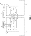
- FIG. 4 is a schematic view of proximity sensor system 10a, which includes active sensor 12, passive target 14, controller 16, first structure 18, second structure 20, system components 22, and measurement circuit 24.
- Active sensor 12 includes active resonant tank circuit 26, which includes capacitor 28, inductor 30, excitation source 32, and current sense resistor 56.
- Passive target 14 includes passive resonant tank circuit 34, which includes capacitor 38and inductor 36. Also shown in FIG. 1 are distance d and magnetic field B.
- Measurement circuit 24 is not physically connected to active object 18 and is not a component of active sensor 12. Additionally, measurement circuit 24 is electrically connected to active resonant tank circuit 26 across current sense resistor 56, which has a resistance R s . However, measurement circuit 24 is still electrically connected to controller 16.
- measurement circuit 24 measures the current across current sense resistor 56.
- Current sense resistor 56 can be either a fixed or variable resistor that enables current measurement. This measurement allows for the electrical response generated by the magnetic coupling of active resonant tank circuit 26 and passive resonant tank circuit 34 to be analyzed in the frequency domain and time domain. In other embodiments, the current can be measured at other parts of active resonant tank circuit 26.
- controller 16 can control system components 22, which can be first structure 18 or second structure 20, based on the measured distance output from measurement circuit 24. Current measurement can also be accomplished by measuring the current through other components of active sensor 12.
- a proximity sensor 2 according to claim 1.
- the proximity sensor of the preceding paragraph can optionally include, additionally and/or alternatively, any one or more of the following features, configurations and/or additional components.
- the active resonant tank circuit and the passive resonant tank circuit can be tuned to substantially equal resonant frequencies.
- the coupled resonant frequency response can be determined by analyzing a voltage across a component of the active resonant tank circuit.
- the coupled resonant frequency response can be determined by analyzing a current through the active resonant tank circuit.
- the measurement circuit can determine a distance between the active sensor and the passive target by analyzing the coupled resonant frequency response versus a coefficient of coupling.
- the measurement circuit can determine a distance between the active sensor and the passive target by analyzing the coupled resonant frequency response in a time domain versus a coefficient of coupling.
- the system of the preceding paragraph can optionally include, additionally and/or alternatively, any one or more of the following features, configurations and/or additional components.
- the active resonant tank circuit and the passive resonant tank circuit can be tuned to substantially equal resonant frequencies.
- the measurement circuit can determine a distance between the active sensor and the passive target by analyzing one of the coupled resonant frequency response versus a coefficient of coupling or the coupled resonant frequency response in a time domain versus a coefficient of coupling.
- a sensing object can attach the active sensor.
- a target object can attach the passive target, and the target object and the sensing object can be movable with respect to one another.
- the controller can control one of the sensing object or the target object based on the measured distance output.
- a method of sensing proximity according to claim 10.
- the method of the preceding paragraph can optionally include, additionally and/or alternatively, any one or more of the following features, configurations and/or additional components, or steps.
- the active resonant tank circuit and the passive resonant tank circuit can be tuned to substantially equal resonant frequencies.
- the measured distance output can be sent to a controller.
- a system component can be controlled based on the measured distance output.
Landscapes
- Physics & Mathematics (AREA)
- General Physics & Mathematics (AREA)
- Measurement Of Length, Angles, Or The Like Using Electric Or Magnetic Means (AREA)
Claims (13)
- Détecteur de proximité, comprenant :un détecteur actif comprenant un circuit réservoir résonnant actif (26) qui comporte une source d'excitation, un premier condensateur et un premier inducteur ;une cible passive (14) comprenant un circuit réservoir résonnant passif (34) qui comporte un second condensateur et un second inducteur, dans lequel le couplage magnétique entre le premier inducteur et le second inducteur varie en fonction de la distance de séparation entre le premier inducteur et le second inducteur en parallèle avec le second condensateur ; etun circuit de mesure (24) conçu pour mesurer une valeur analogique de la réponse en fréquence de résonance couplée dans le circuit réservoir résonnant actif (26) et fournir une sortie de distance mesurée sur la base de la valeur analogique de la réponse en fréquence de résonance couplée, dans lequelle circuit réservoir actif (26) et le circuit réservoir passif ont chacun un facteur de qualité, et dans lequel le circuit réservoir actif (26) a un facteur de qualité Q1 supérieur à un et dans lequel le circuit réservoir passif a un facteur de qualité Q2 supérieur à un,dans lequel la valeur analogique de la réponse en fréquence de résonance couplée varie en fonction de la distance de séparation, etdans lequel la sortie de distance mesurée est un signal qui représente la distance de séparation.
- Détecteur de proximité selon la revendication 1, dans lequel le circuit réservoir résonant actif (26) et le circuit réservoir résonant passif sont accordés à des fréquences de résonance sensiblement égales.
- Détecteur de proximité selon une quelconque revendication précédente, dans lequel la réponse en fréquence de résonance couplée est déterminée en analysant une tension aux bornes d'un composant du circuit réservoir résonant actif.
- Détecteur de proximité selon une quelconque revendication précédente, dans lequel la réponse en fréquence de résonance couplée est déterminée en analysant un courant traversant le circuit réservoir résonant actif (26).
- Détecteur de proximité selon une quelconque revendication précédente, dans lequel le circuit de mesure (24) détermine une distance entre le détecteur actif (12) et la cible passive (14) en analysant la réponse en fréquence de résonance couplée par rapport à un coefficient de couplage.
- Détecteur de proximité selon une quelconque revendication précédente, dans lequel le circuit de mesure (24) détermine une distance entre le détecteur actif (12) et la cible passive (14) en analysant la réponse en fréquence de résonance couplée dans un domaine temporel par rapport à un coefficient de couplage.
- Système de détecteur de proximité comprenant :
le détecteur de proximité selon une quelconque revendication précédente, comprenant en outre :
un dispositif de commande connecté au circuit de mesure pour commander un composant du système sur la base de la sortie de distance mesurée. - Système de détecteur de proximité selon la revendication 7 et comprenant en outre un objet de détection pour fixer le capteur actif, et comprenant de préférence en outre un objet cible pour fixer la cible passive, dans lequel l'objet cible et l'objet de détection sont mobiles l'un par rapport à l'autre.
- Système de capteur de proximité selon la revendication 8, dans lequel le dispositif de commande commande l'un de l'objet de détection ou de l'objet cible sur la base de la sortie de distance mesurée.
- Procédé de détermination de la distance de séparation entre un premier inducteur et un second inducteur, le procédé comprenant :l'alimentation d'un capteur actif comprenant un circuit réservoir résonant actif (26) qui est couplé magnétiquement à un circuit réservoir résonant passif (34) d'une cible passive (14), et dans lequel le couplage magnétique entre le circuit réservoir résonant actif (26) et le circuit réservoir résonnant passif (34) varie en fonction de la distance de séparation entre les circuits réservoirs résonnants actif et passif ;la mesure d'une réponse en fréquence de résonance couplée dans le circuit actif qui est fonction du couplage magnétique entre le circuit réservoir résonant actif (26) et le circuit réservoir résonant passif (34), dans lequel la réponse en fréquence de résonance couplée varie en fonction de la distance de séparation ; etla production d'une sortie de distance mesurée sur la base de la réponse en fréquence de résonance couplée ; dans lequelle circuit réservoir actif (26) et le circuit réservoir passif (34) ont chacun un facteur de qualité, et dans lequel le circuit réservoir actif (26) a un facteur de qualité Q1 supérieur à un et dans lequel le circuit réservoir passif (34) a un facteur de qualité Q2 supérieur à un, et dans lequel la sortie de distance mesurée est un signal qui représente la distance de séparation.
- Procédé de détermination de proximité selon la revendication 10, dans lequel le circuit réservoir résonant actif (26) et le circuit réservoir résonant passif (34) sont accordés à des fréquences de résonance sensiblement égales.
- Procédé de détermination de proximité selon la revendication 10 ou 11, comportant :
l'envoi de la sortie de distance mesurée à un dispositif de commande. - Procédé de détermination de proximité selon l'une quelconque des revendications 10 à 12, comportant :
la commande d'un composant du système sur la base de la sortie de distance mesurée.
Applications Claiming Priority (1)
| Application Number | Priority Date | Filing Date | Title |
|---|---|---|---|
| US14/717,460 US9945695B2 (en) | 2015-05-20 | 2015-05-20 | Proximity sensor |
Publications (2)
| Publication Number | Publication Date |
|---|---|
| EP3096457A1 EP3096457A1 (fr) | 2016-11-23 |
| EP3096457B1 true EP3096457B1 (fr) | 2022-03-23 |
Family
ID=56080251
Family Applications (1)
| Application Number | Title | Priority Date | Filing Date |
|---|---|---|---|
| EP16170295.6A Active EP3096457B1 (fr) | 2015-05-20 | 2016-05-19 | Détecteur de proximité |
Country Status (4)
| Country | Link |
|---|---|
| US (1) | US9945695B2 (fr) |
| EP (1) | EP3096457B1 (fr) |
| BR (1) | BR102016009261B1 (fr) |
| CA (1) | CA2923887C (fr) |
Families Citing this family (6)
| Publication number | Priority date | Publication date | Assignee | Title |
|---|---|---|---|---|
| GB2570533B (en) | 2017-12-20 | 2021-09-22 | Sonuus Ltd | Keyboard sensor systems and methods |
| GB2584763B (en) * | 2018-08-07 | 2023-03-29 | Sonuus Ltd | Computer input devices |
| US11801946B2 (en) * | 2019-04-25 | 2023-10-31 | The Boeing Company | System for sensing miniature gaps by inductive coupling |
| US10976837B2 (en) | 2019-08-20 | 2021-04-13 | Sigmasense, Llc. | User input passive device for use with an interactive display device |
| US11513630B2 (en) * | 2019-08-27 | 2022-11-29 | Samsung Electro-Mechanics Co., Ltd. | Touch operation sensing device using impedance change caused by touch operation |
| US11796577B2 (en) * | 2020-09-09 | 2023-10-24 | Ningbo Aura Semiconductor Co., Limited | Making determination of inductance-change immune to changes in environmental conditions |
Citations (2)
| Publication number | Priority date | Publication date | Assignee | Title |
|---|---|---|---|---|
| US3484787A (en) * | 1967-06-12 | 1969-12-16 | Itt | Folded monopole antenna with top loading and lumped inductance at bottom |
| WO2014156276A1 (fr) * | 2013-03-25 | 2014-10-02 | アズビル株式会社 | Système de capteur de proximité |
Family Cites Families (10)
| Publication number | Priority date | Publication date | Assignee | Title |
|---|---|---|---|---|
| US3609527A (en) | 1969-05-26 | 1971-09-28 | James F Ellis | Noncontacting proximity gage utilizing induced eddy currents,having improved dynamic response and interference discrimination |
| US4005359A (en) * | 1975-11-07 | 1977-01-25 | Smoot William N | Resonant frequency measuring device for gauging coating thickness |
| US5515041A (en) * | 1993-06-14 | 1996-05-07 | Simmonds Precision Products Inc. | Composite shaft monitoring system |
| US7042228B2 (en) * | 2001-04-27 | 2006-05-09 | Oceana Sensor Technologies, Inc. | Transducer in-situ testing apparatus and method |
| US7086593B2 (en) | 2003-04-30 | 2006-08-08 | The United States Of America As Represented By The Administrator Of The National Aeronautics And Space Administration | Magnetic field response measurement acquisition system |
| US7920316B2 (en) * | 2006-02-13 | 2011-04-05 | ISPACE Artlab LLC | Systems and methods for sensory stimulation |
| WO2009068758A1 (fr) | 2007-11-26 | 2009-06-04 | Commissariat A L'energie Atomique | Architecture de telemesure en champ proche pour capteur passif distant de type {r,l,c} |
| US8188730B2 (en) | 2008-09-10 | 2012-05-29 | Rockwell Automation Technologies, Inc. | Method and system for inductive proximity sensing that includes mounting effect compensation |
| US8258777B2 (en) | 2009-09-04 | 2012-09-04 | Weihua Chen | Inductive proximity sensor |
| EP2651036B1 (fr) * | 2012-04-13 | 2014-09-17 | Sick AG | Détecteur d'approximation inductif |
-
2015
- 2015-05-20 US US14/717,460 patent/US9945695B2/en active Active
-
2016
- 2016-03-15 CA CA2923887A patent/CA2923887C/fr active Active
- 2016-04-26 BR BR102016009261-2A patent/BR102016009261B1/pt active IP Right Grant
- 2016-05-19 EP EP16170295.6A patent/EP3096457B1/fr active Active
Patent Citations (2)
| Publication number | Priority date | Publication date | Assignee | Title |
|---|---|---|---|---|
| US3484787A (en) * | 1967-06-12 | 1969-12-16 | Itt | Folded monopole antenna with top loading and lumped inductance at bottom |
| WO2014156276A1 (fr) * | 2013-03-25 | 2014-10-02 | アズビル株式会社 | Système de capteur de proximité |
Non-Patent Citations (1)
| Title |
|---|
| ISRAEL BUIUM: "Two inductively coupled RLC circuits", 8 October 2013 (2013-10-08), XP055462624, Retrieved from the Internet <URL:https://web.archive.org/web/20131008113816/http://www.ee.bgu.ac.il/~intrlab/lab_number_7/Two%20inductively%20coupled%20RLC%20circuits.pdf#expand> [retrieved on 20180326] * |
Also Published As
| Publication number | Publication date |
|---|---|
| US9945695B2 (en) | 2018-04-17 |
| EP3096457A1 (fr) | 2016-11-23 |
| BR102016009261B1 (pt) | 2023-04-04 |
| US20160341572A1 (en) | 2016-11-24 |
| BR102016009261A2 (pt) | 2016-11-22 |
| CA2923887C (fr) | 2023-02-28 |
| CA2923887A1 (fr) | 2016-11-20 |
Similar Documents
| Publication | Publication Date | Title |
|---|---|---|
| US9945695B2 (en) | Proximity sensor | |
| US8008909B2 (en) | Analysis and compensation circuit for an inductive displacement sensor | |
| EP3702738B1 (fr) | Procédé d'amélioration de la précision de mesure de position à l'aide d'un capteur de position inductif | |
| EP2338032B1 (fr) | Détecteur de position | |
| JP5631186B2 (ja) | 媒体に封入されたオブジェクトの検出方法、ならびに該検出方法を実施するための測定装置 | |
| US20100090688A1 (en) | Method and sensor arrangement for determining the position and/or change of position of a measured object relative to a sensor | |
| US11460287B2 (en) | Inductive analysis of metal objects | |
| US6474158B2 (en) | Apparatus for measuring displacement and method of use thereof | |
| EP3376171B1 (fr) | Capteur de position de course étendue | |
| EP1988409A2 (fr) | Dispositif et procédé de détection d'objets ferrites et non ferrites | |
| US11567229B2 (en) | Detector for detecting electrically conductive material | |
| JPH0257984A (ja) | 薄層のオーム抵抗の非破壊測定用の誘導性および容量性装置の結合された適用のための回路装置 | |
| US20080129276A1 (en) | Method for Locating Objects Enclosed in a Medium, and Measuring Device for Carrying Out the Method | |
| Jagiella et al. | New magneto-inductive sensing principle and its implementation in sensors for industrial applications | |
| JP4398911B2 (ja) | 変位センサ | |
| US20220020519A1 (en) | Method and device for controlling an armature solenoid | |
| US12442904B2 (en) | Compensation for an ultrasonic transducer with a variable compensation inductance | |
| US11713982B2 (en) | Proximity sensor and method of use | |
| US6538428B1 (en) | Measuring method for mechatronics | |
| US20200256907A1 (en) | Inductive sensor and method for the operation thereof | |
| JPH06334507A (ja) | 高周波発振型近接センサ | |
| US12181312B2 (en) | Linear position sensing components | |
| CN106895774A (zh) | 用于确定相对偏移的装置和方法 | |
| JP2005214762A (ja) | 位置検出装置 |
Legal Events
| Date | Code | Title | Description |
|---|---|---|---|
| PUAI | Public reference made under article 153(3) epc to a published international application that has entered the european phase |
Free format text: ORIGINAL CODE: 0009012 |
|
| AK | Designated contracting states |
Kind code of ref document: A1 Designated state(s): AL AT BE BG CH CY CZ DE DK EE ES FI FR GB GR HR HU IE IS IT LI LT LU LV MC MK MT NL NO PL PT RO RS SE SI SK SM TR |
|
| AX | Request for extension of the european patent |
Extension state: BA ME |
|
| STAA | Information on the status of an ep patent application or granted ep patent |
Free format text: STATUS: REQUEST FOR EXAMINATION WAS MADE |
|
| 17P | Request for examination filed |
Effective date: 20170518 |
|
| RBV | Designated contracting states (corrected) |
Designated state(s): AL AT BE BG CH CY CZ DE DK EE ES FI FR GB GR HR HU IE IS IT LI LT LU LV MC MK MT NL NO PL PT RO RS SE SI SK SM TR |
|
| STAA | Information on the status of an ep patent application or granted ep patent |
Free format text: STATUS: EXAMINATION IS IN PROGRESS |
|
| 17Q | First examination report despatched |
Effective date: 20180403 |
|
| GRAP | Despatch of communication of intention to grant a patent |
Free format text: ORIGINAL CODE: EPIDOSNIGR1 |
|
| STAA | Information on the status of an ep patent application or granted ep patent |
Free format text: STATUS: GRANT OF PATENT IS INTENDED |
|
| INTG | Intention to grant announced |
Effective date: 20211108 |
|
| GRAS | Grant fee paid |
Free format text: ORIGINAL CODE: EPIDOSNIGR3 |
|
| GRAA | (expected) grant |
Free format text: ORIGINAL CODE: 0009210 |
|
| STAA | Information on the status of an ep patent application or granted ep patent |
Free format text: STATUS: THE PATENT HAS BEEN GRANTED |
|
| AK | Designated contracting states |
Kind code of ref document: B1 Designated state(s): AL AT BE BG CH CY CZ DE DK EE ES FI FR GB GR HR HU IE IS IT LI LT LU LV MC MK MT NL NO PL PT RO RS SE SI SK SM TR |
|
| REG | Reference to a national code |
Ref country code: GB Ref legal event code: FG4D |
|
| REG | Reference to a national code |
Ref country code: CH Ref legal event code: EP |
|
| REG | Reference to a national code |
Ref country code: IE Ref legal event code: FG4D |
|
| REG | Reference to a national code |
Ref country code: DE Ref legal event code: R096 Ref document number: 602016070198 Country of ref document: DE |
|
| REG | Reference to a national code |
Ref country code: AT Ref legal event code: REF Ref document number: 1478147 Country of ref document: AT Kind code of ref document: T Effective date: 20220415 |
|
| REG | Reference to a national code |
Ref country code: FR Ref legal event code: PLFP Year of fee payment: 7 |
|
| REG | Reference to a national code |
Ref country code: LT Ref legal event code: MG9D |
|
| REG | Reference to a national code |
Ref country code: NL Ref legal event code: MP Effective date: 20220323 |
|
| PG25 | Lapsed in a contracting state [announced via postgrant information from national office to epo] |
Ref country code: SE Free format text: LAPSE BECAUSE OF FAILURE TO SUBMIT A TRANSLATION OF THE DESCRIPTION OR TO PAY THE FEE WITHIN THE PRESCRIBED TIME-LIMIT Effective date: 20220323 Ref country code: RS Free format text: LAPSE BECAUSE OF FAILURE TO SUBMIT A TRANSLATION OF THE DESCRIPTION OR TO PAY THE FEE WITHIN THE PRESCRIBED TIME-LIMIT Effective date: 20220323 Ref country code: NO Free format text: LAPSE BECAUSE OF FAILURE TO SUBMIT A TRANSLATION OF THE DESCRIPTION OR TO PAY THE FEE WITHIN THE PRESCRIBED TIME-LIMIT Effective date: 20220623 Ref country code: LT Free format text: LAPSE BECAUSE OF FAILURE TO SUBMIT A TRANSLATION OF THE DESCRIPTION OR TO PAY THE FEE WITHIN THE PRESCRIBED TIME-LIMIT Effective date: 20220323 Ref country code: HR Free format text: LAPSE BECAUSE OF FAILURE TO SUBMIT A TRANSLATION OF THE DESCRIPTION OR TO PAY THE FEE WITHIN THE PRESCRIBED TIME-LIMIT Effective date: 20220323 Ref country code: BG Free format text: LAPSE BECAUSE OF FAILURE TO SUBMIT A TRANSLATION OF THE DESCRIPTION OR TO PAY THE FEE WITHIN THE PRESCRIBED TIME-LIMIT Effective date: 20220623 |
|
| REG | Reference to a national code |
Ref country code: AT Ref legal event code: MK05 Ref document number: 1478147 Country of ref document: AT Kind code of ref document: T Effective date: 20220323 |
|
| PG25 | Lapsed in a contracting state [announced via postgrant information from national office to epo] |
Ref country code: LV Free format text: LAPSE BECAUSE OF FAILURE TO SUBMIT A TRANSLATION OF THE DESCRIPTION OR TO PAY THE FEE WITHIN THE PRESCRIBED TIME-LIMIT Effective date: 20220323 Ref country code: GR Free format text: LAPSE BECAUSE OF FAILURE TO SUBMIT A TRANSLATION OF THE DESCRIPTION OR TO PAY THE FEE WITHIN THE PRESCRIBED TIME-LIMIT Effective date: 20220624 Ref country code: FI Free format text: LAPSE BECAUSE OF FAILURE TO SUBMIT A TRANSLATION OF THE DESCRIPTION OR TO PAY THE FEE WITHIN THE PRESCRIBED TIME-LIMIT Effective date: 20220323 |
|
| PG25 | Lapsed in a contracting state [announced via postgrant information from national office to epo] |
Ref country code: NL Free format text: LAPSE BECAUSE OF FAILURE TO SUBMIT A TRANSLATION OF THE DESCRIPTION OR TO PAY THE FEE WITHIN THE PRESCRIBED TIME-LIMIT Effective date: 20220323 |
|
| PG25 | Lapsed in a contracting state [announced via postgrant information from national office to epo] |
Ref country code: SM Free format text: LAPSE BECAUSE OF FAILURE TO SUBMIT A TRANSLATION OF THE DESCRIPTION OR TO PAY THE FEE WITHIN THE PRESCRIBED TIME-LIMIT Effective date: 20220323 Ref country code: SK Free format text: LAPSE BECAUSE OF FAILURE TO SUBMIT A TRANSLATION OF THE DESCRIPTION OR TO PAY THE FEE WITHIN THE PRESCRIBED TIME-LIMIT Effective date: 20220323 Ref country code: RO Free format text: LAPSE BECAUSE OF FAILURE TO SUBMIT A TRANSLATION OF THE DESCRIPTION OR TO PAY THE FEE WITHIN THE PRESCRIBED TIME-LIMIT Effective date: 20220323 Ref country code: PT Free format text: LAPSE BECAUSE OF FAILURE TO SUBMIT A TRANSLATION OF THE DESCRIPTION OR TO PAY THE FEE WITHIN THE PRESCRIBED TIME-LIMIT Effective date: 20220725 Ref country code: ES Free format text: LAPSE BECAUSE OF FAILURE TO SUBMIT A TRANSLATION OF THE DESCRIPTION OR TO PAY THE FEE WITHIN THE PRESCRIBED TIME-LIMIT Effective date: 20220323 Ref country code: EE Free format text: LAPSE BECAUSE OF FAILURE TO SUBMIT A TRANSLATION OF THE DESCRIPTION OR TO PAY THE FEE WITHIN THE PRESCRIBED TIME-LIMIT Effective date: 20220323 Ref country code: CZ Free format text: LAPSE BECAUSE OF FAILURE TO SUBMIT A TRANSLATION OF THE DESCRIPTION OR TO PAY THE FEE WITHIN THE PRESCRIBED TIME-LIMIT Effective date: 20220323 Ref country code: AT Free format text: LAPSE BECAUSE OF FAILURE TO SUBMIT A TRANSLATION OF THE DESCRIPTION OR TO PAY THE FEE WITHIN THE PRESCRIBED TIME-LIMIT Effective date: 20220323 |
|
| PG25 | Lapsed in a contracting state [announced via postgrant information from national office to epo] |
Ref country code: PL Free format text: LAPSE BECAUSE OF FAILURE TO SUBMIT A TRANSLATION OF THE DESCRIPTION OR TO PAY THE FEE WITHIN THE PRESCRIBED TIME-LIMIT Effective date: 20220323 Ref country code: IS Free format text: LAPSE BECAUSE OF FAILURE TO SUBMIT A TRANSLATION OF THE DESCRIPTION OR TO PAY THE FEE WITHIN THE PRESCRIBED TIME-LIMIT Effective date: 20220723 Ref country code: AL Free format text: LAPSE BECAUSE OF FAILURE TO SUBMIT A TRANSLATION OF THE DESCRIPTION OR TO PAY THE FEE WITHIN THE PRESCRIBED TIME-LIMIT Effective date: 20220323 |
|
| REG | Reference to a national code |
Ref country code: CH Ref legal event code: PL |
|
| REG | Reference to a national code |
Ref country code: DE Ref legal event code: R097 Ref document number: 602016070198 Country of ref document: DE |
|
| REG | Reference to a national code |
Ref country code: BE Ref legal event code: MM Effective date: 20220531 |
|
| PLBE | No opposition filed within time limit |
Free format text: ORIGINAL CODE: 0009261 |
|
| STAA | Information on the status of an ep patent application or granted ep patent |
Free format text: STATUS: NO OPPOSITION FILED WITHIN TIME LIMIT |
|
| PG25 | Lapsed in a contracting state [announced via postgrant information from national office to epo] |
Ref country code: MC Free format text: LAPSE BECAUSE OF FAILURE TO SUBMIT A TRANSLATION OF THE DESCRIPTION OR TO PAY THE FEE WITHIN THE PRESCRIBED TIME-LIMIT Effective date: 20220323 Ref country code: LU Free format text: LAPSE BECAUSE OF NON-PAYMENT OF DUE FEES Effective date: 20220519 Ref country code: LI Free format text: LAPSE BECAUSE OF NON-PAYMENT OF DUE FEES Effective date: 20220531 Ref country code: DK Free format text: LAPSE BECAUSE OF FAILURE TO SUBMIT A TRANSLATION OF THE DESCRIPTION OR TO PAY THE FEE WITHIN THE PRESCRIBED TIME-LIMIT Effective date: 20220323 Ref country code: CH Free format text: LAPSE BECAUSE OF NON-PAYMENT OF DUE FEES Effective date: 20220531 |
|
| 26N | No opposition filed |
Effective date: 20230102 |
|
| PG25 | Lapsed in a contracting state [announced via postgrant information from national office to epo] |
Ref country code: IE Free format text: LAPSE BECAUSE OF NON-PAYMENT OF DUE FEES Effective date: 20220519 |
|
| PG25 | Lapsed in a contracting state [announced via postgrant information from national office to epo] |
Ref country code: SI Free format text: LAPSE BECAUSE OF FAILURE TO SUBMIT A TRANSLATION OF THE DESCRIPTION OR TO PAY THE FEE WITHIN THE PRESCRIBED TIME-LIMIT Effective date: 20220323 Ref country code: BE Free format text: LAPSE BECAUSE OF NON-PAYMENT OF DUE FEES Effective date: 20220531 |
|
| PG25 | Lapsed in a contracting state [announced via postgrant information from national office to epo] |
Ref country code: IT Free format text: LAPSE BECAUSE OF FAILURE TO SUBMIT A TRANSLATION OF THE DESCRIPTION OR TO PAY THE FEE WITHIN THE PRESCRIBED TIME-LIMIT Effective date: 20220323 |
|
| PG25 | Lapsed in a contracting state [announced via postgrant information from national office to epo] |
Ref country code: HU Free format text: LAPSE BECAUSE OF FAILURE TO SUBMIT A TRANSLATION OF THE DESCRIPTION OR TO PAY THE FEE WITHIN THE PRESCRIBED TIME-LIMIT; INVALID AB INITIO Effective date: 20160519 |
|
| PG25 | Lapsed in a contracting state [announced via postgrant information from national office to epo] |
Ref country code: MK Free format text: LAPSE BECAUSE OF FAILURE TO SUBMIT A TRANSLATION OF THE DESCRIPTION OR TO PAY THE FEE WITHIN THE PRESCRIBED TIME-LIMIT Effective date: 20220323 Ref country code: CY Free format text: LAPSE BECAUSE OF FAILURE TO SUBMIT A TRANSLATION OF THE DESCRIPTION OR TO PAY THE FEE WITHIN THE PRESCRIBED TIME-LIMIT Effective date: 20220323 |
|
| PG25 | Lapsed in a contracting state [announced via postgrant information from national office to epo] |
Ref country code: MT Free format text: LAPSE BECAUSE OF FAILURE TO SUBMIT A TRANSLATION OF THE DESCRIPTION OR TO PAY THE FEE WITHIN THE PRESCRIBED TIME-LIMIT Effective date: 20220323 |
|
| PG25 | Lapsed in a contracting state [announced via postgrant information from national office to epo] |
Ref country code: TR Free format text: LAPSE BECAUSE OF FAILURE TO SUBMIT A TRANSLATION OF THE DESCRIPTION OR TO PAY THE FEE WITHIN THE PRESCRIBED TIME-LIMIT Effective date: 20220323 |
|
| PGFP | Annual fee paid to national office [announced via postgrant information from national office to epo] |
Ref country code: GB Payment date: 20260518 Year of fee payment: 11 |
|
| PGFP | Annual fee paid to national office [announced via postgrant information from national office to epo] |
Ref country code: DE Payment date: 20260512 Year of fee payment: 11 |
|
| PGFP | Annual fee paid to national office [announced via postgrant information from national office to epo] |
Ref country code: FR Payment date: 20260521 Year of fee payment: 11 |