EP3096809B1 - Dialysegerät mit einem dialysator - Google Patents
Dialysegerät mit einem dialysator Download PDFInfo
- Publication number
- EP3096809B1 EP3096809B1 EP15700184.3A EP15700184A EP3096809B1 EP 3096809 B1 EP3096809 B1 EP 3096809B1 EP 15700184 A EP15700184 A EP 15700184A EP 3096809 B1 EP3096809 B1 EP 3096809B1
- Authority
- EP
- European Patent Office
- Prior art keywords
- type
- capillary
- blood
- adapter
- dialyzer
- Prior art date
- Legal status (The legal status is an assumption and is not a legal conclusion. Google has not performed a legal analysis and makes no representation as to the accuracy of the status listed.)
- Active
Links
- 238000000502 dialysis Methods 0.000 title claims description 23
- 210000001601 blood-air barrier Anatomy 0.000 claims description 48
- 239000008280 blood Substances 0.000 claims description 27
- 210000004369 blood Anatomy 0.000 claims description 27
- 239000011148 porous material Substances 0.000 claims description 21
- 230000017531 blood circulation Effects 0.000 claims description 14
- 230000004087 circulation Effects 0.000 claims 2
- 239000012528 membrane Substances 0.000 description 9
- 238000000108 ultra-filtration Methods 0.000 description 7
- 241000894006 Bacteria Species 0.000 description 5
- 241000700605 Viruses Species 0.000 description 5
- 238000001631 haemodialysis Methods 0.000 description 4
- 230000000322 hemodialysis Effects 0.000 description 4
- 238000000034 method Methods 0.000 description 4
- 238000011282 treatment Methods 0.000 description 4
- 210000000245 forearm Anatomy 0.000 description 3
- 238000010521 absorption reaction Methods 0.000 description 2
- 239000007844 bleaching agent Substances 0.000 description 2
- DDRJAANPRJIHGJ-UHFFFAOYSA-N creatinine Chemical compound CN1CC(=O)NC1=N DDRJAANPRJIHGJ-UHFFFAOYSA-N 0.000 description 2
- 238000009792 diffusion process Methods 0.000 description 2
- 230000000694 effects Effects 0.000 description 2
- 239000002158 endotoxin Substances 0.000 description 2
- 210000003734 kidney Anatomy 0.000 description 2
- 238000012958 reprocessing Methods 0.000 description 2
- XLYOFNOQVPJJNP-UHFFFAOYSA-N water Substances O XLYOFNOQVPJJNP-UHFFFAOYSA-N 0.000 description 2
- 206010019280 Heart failures Diseases 0.000 description 1
- XSQUKJJJFZCRTK-UHFFFAOYSA-N Urea Chemical compound NC(N)=O XSQUKJJJFZCRTK-UHFFFAOYSA-N 0.000 description 1
- 239000003146 anticoagulant agent Substances 0.000 description 1
- 229940127219 anticoagulant drug Drugs 0.000 description 1
- 230000010100 anticoagulation Effects 0.000 description 1
- 102000015736 beta 2-Microglobulin Human genes 0.000 description 1
- 108010081355 beta 2-Microglobulin Proteins 0.000 description 1
- 238000004061 bleaching Methods 0.000 description 1
- 239000003130 blood coagulation factor inhibitor Substances 0.000 description 1
- 239000004202 carbamide Substances 0.000 description 1
- 238000003889 chemical engineering Methods 0.000 description 1
- 229940109239 creatinine Drugs 0.000 description 1
- 239000000385 dialysis solution Substances 0.000 description 1
- 230000007717 exclusion Effects 0.000 description 1
- 239000000284 extract Substances 0.000 description 1
- 238000003780 insertion Methods 0.000 description 1
- 230000037431 insertion Effects 0.000 description 1
- 239000000463 material Substances 0.000 description 1
- 239000000203 mixture Substances 0.000 description 1
- 229920002492 poly(sulfone) Polymers 0.000 description 1
- 229920000642 polymer Polymers 0.000 description 1
- 238000012959 renal replacement therapy Methods 0.000 description 1
- 238000009256 replacement therapy Methods 0.000 description 1
- 238000001179 sorption measurement Methods 0.000 description 1
- 230000000087 stabilizing effect Effects 0.000 description 1
- 239000000126 substance Substances 0.000 description 1
- 229920001059 synthetic polymer Polymers 0.000 description 1
- 231100000331 toxic Toxicity 0.000 description 1
- 230000002588 toxic effect Effects 0.000 description 1
- 239000003053 toxin Substances 0.000 description 1
- 231100000765 toxin Toxicity 0.000 description 1
- 108700012359 toxins Proteins 0.000 description 1
- 230000002485 urinary effect Effects 0.000 description 1
- 230000002792 vascular Effects 0.000 description 1
- 238000005406 washing Methods 0.000 description 1
- 239000002699 waste material Substances 0.000 description 1
Images


Classifications
-
- A—HUMAN NECESSITIES
- A61—MEDICAL OR VETERINARY SCIENCE; HYGIENE
- A61M—DEVICES FOR INTRODUCING MEDIA INTO, OR ONTO, THE BODY; DEVICES FOR TRANSDUCING BODY MEDIA OR FOR TAKING MEDIA FROM THE BODY; DEVICES FOR PRODUCING OR ENDING SLEEP OR STUPOR
- A61M1/00—Suction or pumping devices for medical purposes; Devices for carrying-off, for treatment of, or for carrying-over, body-liquids; Drainage systems
- A61M1/14—Dialysis systems; Artificial kidneys; Blood oxygenators ; Reciprocating systems for treatment of body fluids, e.g. single needle systems for hemofiltration or pheresis
- A61M1/16—Dialysis systems; Artificial kidneys; Blood oxygenators ; Reciprocating systems for treatment of body fluids, e.g. single needle systems for hemofiltration or pheresis with membranes
- A61M1/1621—Constructional aspects thereof
- A61M1/1623—Disposition or location of membranes relative to fluids
- A61M1/1625—Dialyser of the outside perfusion type, i.e. blood flow outside hollow membrane fibres or tubes
-
- A—HUMAN NECESSITIES
- A61—MEDICAL OR VETERINARY SCIENCE; HYGIENE
- A61M—DEVICES FOR INTRODUCING MEDIA INTO, OR ONTO, THE BODY; DEVICES FOR TRANSDUCING BODY MEDIA OR FOR TAKING MEDIA FROM THE BODY; DEVICES FOR PRODUCING OR ENDING SLEEP OR STUPOR
- A61M1/00—Suction or pumping devices for medical purposes; Devices for carrying-off, for treatment of, or for carrying-over, body-liquids; Drainage systems
- A61M1/36—Other treatment of blood in a by-pass of the natural circulatory system, e.g. temperature adaptation, irradiation ; Extra-corporeal blood circuits
- A61M1/3672—Means preventing coagulation
-
- B—PERFORMING OPERATIONS; TRANSPORTING
- B01—PHYSICAL OR CHEMICAL PROCESSES OR APPARATUS IN GENERAL
- B01D—SEPARATION
- B01D63/00—Apparatus in general for separation processes using semi-permeable membranes
- B01D63/02—Hollow fibre modules
- B01D63/04—Hollow fibre modules comprising multiple hollow fibre assemblies
-
- B—PERFORMING OPERATIONS; TRANSPORTING
- B01—PHYSICAL OR CHEMICAL PROCESSES OR APPARATUS IN GENERAL
- B01D—SEPARATION
- B01D69/00—Semi-permeable membranes for separation processes or apparatus characterised by their form, structure or properties; Manufacturing processes specially adapted therefor
- B01D69/02—Semi-permeable membranes for separation processes or apparatus characterised by their form, structure or properties; Manufacturing processes specially adapted therefor characterised by their properties
-
- B—PERFORMING OPERATIONS; TRANSPORTING
- B01—PHYSICAL OR CHEMICAL PROCESSES OR APPARATUS IN GENERAL
- B01D—SEPARATION
- B01D69/00—Semi-permeable membranes for separation processes or apparatus characterised by their form, structure or properties; Manufacturing processes specially adapted therefor
- B01D69/08—Hollow fibre membranes
-
- A—HUMAN NECESSITIES
- A61—MEDICAL OR VETERINARY SCIENCE; HYGIENE
- A61M—DEVICES FOR INTRODUCING MEDIA INTO, OR ONTO, THE BODY; DEVICES FOR TRANSDUCING BODY MEDIA OR FOR TAKING MEDIA FROM THE BODY; DEVICES FOR PRODUCING OR ENDING SLEEP OR STUPOR
- A61M2205/00—General characteristics of the apparatus
- A61M2205/75—General characteristics of the apparatus with filters
- A61M2205/7509—General characteristics of the apparatus with filters for virus
-
- A—HUMAN NECESSITIES
- A61—MEDICAL OR VETERINARY SCIENCE; HYGIENE
- A61M—DEVICES FOR INTRODUCING MEDIA INTO, OR ONTO, THE BODY; DEVICES FOR TRANSDUCING BODY MEDIA OR FOR TAKING MEDIA FROM THE BODY; DEVICES FOR PRODUCING OR ENDING SLEEP OR STUPOR
- A61M2205/00—General characteristics of the apparatus
- A61M2205/75—General characteristics of the apparatus with filters
- A61M2205/7518—General characteristics of the apparatus with filters bacterial
-
- B—PERFORMING OPERATIONS; TRANSPORTING
- B01—PHYSICAL OR CHEMICAL PROCESSES OR APPARATUS IN GENERAL
- B01D—SEPARATION
- B01D2325/00—Details relating to properties of membranes
- B01D2325/02—Details relating to pores or porosity of the membranes
- B01D2325/022—Asymmetric membranes
-
- B—PERFORMING OPERATIONS; TRANSPORTING
- B01—PHYSICAL OR CHEMICAL PROCESSES OR APPARATUS IN GENERAL
- B01D—SEPARATION
- B01D2325/00—Details relating to properties of membranes
- B01D2325/02—Details relating to pores or porosity of the membranes
- B01D2325/0283—Pore size
- B01D2325/02832—1-10 nm
-
- B—PERFORMING OPERATIONS; TRANSPORTING
- B01—PHYSICAL OR CHEMICAL PROCESSES OR APPARATUS IN GENERAL
- B01D—SEPARATION
- B01D2325/00—Details relating to properties of membranes
- B01D2325/02—Details relating to pores or porosity of the membranes
- B01D2325/0283—Pore size
- B01D2325/02833—Pore size more than 10 and up to 100 nm
Definitions
- the invention relates to a dialysis machine according to claim 1 having a dialyzer with a bundle of capillary membranes each having an outer surface and an inner surface and having a larger average pore size in the region of the outer surface than in the region of the inner surface of a blood circulation and a Dialysat Vietnameselaufes.
- dialyzers with capillary membranes are used for the most part, which remove the low-molecular toxic urinary substances, such as urea and creatinine, from the blood in the basic treatment by so-called "low-flux dialyzers".
- high-flux membranes additionally allow some of the medium molecular weight rententionstoxins to pass through, e.g. B. ⁇ 2-microglobulin ( ⁇ 2-M).
- B. ⁇ 2-microglobulin ( ⁇ 2-M) ⁇ 2-microglobulin
- high-flux dialysis not only benefits from the large pore sizes but also from convective (filtrate-tow-solvent-drag) processes.
- capillary membranes made of polysulfone show a thin, about one micron thick membrane structure, which is mechanically strengthened by a 40 ⁇ m thick, stabilizing and increasingly porous support structure. Due to its polymer composition, this supporting layer is able to absorb various molecules, including endotoxins, bacteria and viruses.
- WO 2013/106109 A1 is a hemofilter disclosed for the treatment of heart failure.
- the blood circulation is guided around capillary membranes on the outside. From the blood, leucocytes deposit on the membrane wall.
- an adapter is disclosed.
- the adapter is used to disinfect a dialyzer between different treatments.
- the invention is a dialysis machine according to claim 1 and makes use of the idea to reverse the conventional ultrafiltration direction along the capillary membranes of the dialyzer.
- the invention Blood circulation passed along the outer surface of the capillary and the dialysate run along the inner surfaces of the Kapillarmembranen.
- the blood thus flows along the outer surface provided with larger pores.
- viruses, bacteria and endotoxins can become entangled in the course of an ultrafiltration from the outside in, thereby removing the patient's blood by adsorption or size exclusion.
- the actual dialysis process which takes place via the inner surface with a small pore size, takes place in principle in a conventional manner.
- an average pore size on an outer surface of the capillary membrane is between 1-4 microns and, conveniently, an average pore size of an inner surface of a capillary membrane is less than 5 nm.
- Bacteria and viruses are between 40 nm and a few microns in size, thus entering the interior the capillary membrane wall over the large pores of the outer surface and get caught there. They therefore do not remain in the bloodstream as in conventional dialysis, but are absorbed from it.
- the capillary membranes have a circular inner surface and a circular outer surface in a cross section perpendicular to a longitudinal direction, preferably the Kapillarmembranen along their entire longitudinal extension tubular and formed along its entire longitudinal extent in cross section in both the inner and in the outer surface circular.
- the capillary membranes are easy to produce.
- the capillary membranes are part of a dialyzer, which is externally formed by a housing.
- the bundle is arranged on capillary membranes.
- the capillary membranes are preferably arranged parallel to one another and cast into a holder at their open ends, whereby a blood compartment, which is part of the blood circulation, is formed between the outer surface of the capillary membranes and the inner wall of the housing, while lumens of the capillaries form and form a section of the dialysate circuit Form dialysate compartment.
- Dialysate compartment and blood compartment are separated from each other by the semipermeable capillary membranes. Through the capillary membranes, the actual ultrafiltration process takes place.
- the bundle of capillary membranes is arranged to extend longitudinally, and the blood compartment has two second types of mother connector and the dialysate compartment has two second ones Father connector types, which are each arranged at opposite ends in the longitudinal direction of the respective compartment.
- the two types of mother connectors each cooperate with a blood circulation connector which is arranged at each end of a blood circulation tube.
- two second father connectors are arranged on the housing of the dialyzer, and a second adapter type is placed on each of the two second parent connectors, each having a free after insertion second mother connector, which is intended for connection to a blood circulation adapter, and the housing of the dialyzer two second mother connectors arranged, and on the two second mother connectors each have a first adapter type is placed, each having a free second Vaterkonnketortyp which is intended for connection to a dialysate.
- the blood circulation adapter and the dialysate circuit adapter of the conventional dialysis machines can be maintained, and at the same time the blood compartment and dialysate compartment are interchanged to achieve the essential reversal of the ultrafiltration direction according to the invention.
- Fig. 1 schematically shows the basic structure of a dialysis machine for performing hemodialysis on a patient.
- blood 10 of the patient is washed extracorporeally.
- Fig. 1 shows a forearm 1 of the patient.
- the blood 10 is removed via an access 2 on the forearm 1 of the patient by means of a vascular access and conveyed by means of a blood pump 3 via the access 2 and fed to a dialyzer 4.
- the blood 10 removed from the patient is additionally supplied with a coagulation inhibitor in a feeding device 5, and the blood 10 enriched with the anticoagulant is pumped into the dialyzer 4 and washed in the dialyzer 4.
- the dialyzer 4 serves as the actual "artificial kidney” washes the waste products from the flowing blood 10 of the patient and the water flowing through 10 extracts water.
- the dialyzer 4 comprises a section of an extracorporeal blood circuit 6 and a section of a dialysate circuit 7 separated therefrom.
- the dialyzer is supplied with blood 10 through the blood circulation 6 and through the dialysate circuit 7 with dialysis fluid, also called dialysate.
- the section of the circulatory system 6 and the section of the dialysate circuit 7 are in opposite directions in the dialyzer 4 and separated from each other by semipermeable capillary membranes 8.
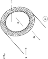
- the semipermeable capillary membranes 8 are in Fig. 2 shown in a perspective view. In Fig. 1 the capillary membranes 8 are represented by three continuous lines marked with a flow direction. In the dialyzer about 10,000 Kapillarmembarnen are next to each other, arranged mainly parallel to each other. Each of the capillary membranes 8 is lapped by the blood 10 of the portion of the bloodstream 6.
- the dialyzer 4 is according to Fig. 1 essentially of the multiplicity of capillary membranes 8 arranged parallel to each other in a longitudinal direction L.
- Capillary membranes 8 are small diameter hair-thin tubes having an inside diameter of between 150 ⁇ m and 240 ⁇ m and an outside diameter of between 200 ⁇ m and larger than 300 ⁇ m ,
- the capillary membranes 8 are arranged parallel to one another, preferably without direct contact with one another in the dialyzer 4.
- a lumen 11 of each of the capillary membranes 8, that is, through the respective free inner tube of the capillary 8 flows a dialysate 9 of the dialysate 7 in the longitudinal direction L of each of the capillary 8.
- each of the Kapillarmembranen 8 flows in the opposite direction, ie opposite to the longitudinal direction L, the blood 10 in the bloodstream 6 at the Kapillarmembranen 8 outside.
- the capillary membranes 8 are each formed semipermeable.
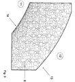
- the Fig. 3 shows a section of the wall of the capillary 8 in Fig. 2
- the wall of the capillary membrane 8 is preferably made of fully synthetic polymers and is constructed asymmetrically in the radial direction. In the longitudinal direction L, however, the capillary membrane 8 is formed substantially translationally invariant.
- the capillary membranes 8 have an outer surface 13 and an inner surface 14, wherein the inner surface 14 has a very fine membrane structure, ie a low membrane thickness of about 1 micron and a pore size of ⁇ 5nm on average, while the Kapillarmembranwand 8 toward the outer surface 13 an increasing has larger pore size and the pore size here is preferably 1 - 4 microns.
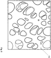
- the inner surface 14 of the capillary membrane 8 is also mechanically strengthened by the increasingly porous support structure. The different pore sizes of the outer surface 13 and inner surface 14 are shown by a comparison of the same scale Figures 3 and 4 clear.
- the blood circulation 6 and the dialysate 7 are reversed.
- the blood 10 is passed through the lumen 11 of the capillary membranes 8 and the dialyzate 9 in countercurrent to the outside around the capillary membranes 8.
- the procedure is exactly the reverse, in that the dialysate 9 flows through the lumen 11 of the capillary membranes 8 and the blood 10 flows around the capillary membrane 8 from the outside.
- the direction of the ultrafiltration is reversed and takes place from the outside in the direction of the lumen 11 of the capillary 8.
- the very large inner surface of the capillary membrane 8 formed by the pores is estimated to be determined.
- the large absorption surface in the wall of the capillary membrane 8 can be used for the removal of large molecular toxins, bacteria or viruses, which as it were stuck in the pores of the capillary 8 during ultrafiltration, since the porosity is fine from the outside in.
- dialysis in the capillary membranes 8 continues to take place by diffusion and convection, depending on the type of dialyzer and method.
- a conventional dialyzer 4 can be used as a component of the dialysis machine according to the invention.
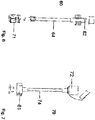
- the dialyzer 4 by two first and two second adapter types 60, 70 in the Fig. 6 or 7 extended.
- the dialyzer 4 has two second mother connector types 61, which in Fig. 1 are provided on the front sides of the dialyzer 4 and in liquid-conducting connection with the lumen 11 of the Kapillarmambranen eighth stand.
- the dialyzer 4 has two second father connector types 71 on the cylindrical outer wall.
- the first adapter type 60 has a first father connector type 62 and a second father connector type 71.
- First father connector type 62 and second father connector type 71 are disposed at different ends of a first tube 64 and face each other.
- the second adapter type 70 has a first mother connector type 72 and a second mother connector type 61.
- First nut connector type 72 and second nut connector type 61 are disposed opposite each other at different ends of a second tube 74.
- the second father connector types 71 which are arranged on the outer wall of the dialyzer 4, and the second father connector types 71 on the first adapter type 60 are not necessarily identical, but only functionally identical, in the sense that they form a fluid-tight connection with a first mother connector type 72 , The same applies to the second mother connector type 61, which must form a fluid-tight connection with the first father connector type 62.
- a first adapter type 60 with its first father connector type 62 is attached in each case.
- the second type of mother connector 61 is an internal thread
- the first type of connector connector 62 is an external thread.
- a second adapter type 70 with its first mother connector type 72 is attached to the second father connector type 71 in each case. This is a plug connection.
- the two second mother connector types 61 which depart from the second adapter type 70, are each connected to a blood circulation adapter 80.
- the two second father connector types 71 are each connected to a dialysate circuit adapter 81.
- the two adapter types 60, 70 thus exchange the connector types of conventional dialyzers 4.
Landscapes
- Health & Medical Sciences (AREA)
- Heart & Thoracic Surgery (AREA)
- Vascular Medicine (AREA)
- Urology & Nephrology (AREA)
- Chemical Kinetics & Catalysis (AREA)
- Chemical & Material Sciences (AREA)
- Animal Behavior & Ethology (AREA)
- Engineering & Computer Science (AREA)
- Anesthesiology (AREA)
- Biomedical Technology (AREA)
- Hematology (AREA)
- Life Sciences & Earth Sciences (AREA)
- General Health & Medical Sciences (AREA)
- Public Health (AREA)
- Veterinary Medicine (AREA)
- Emergency Medicine (AREA)
- Cardiology (AREA)
- External Artificial Organs (AREA)
Description
- Die Erfindung betrifft ein Dialysegerät nach Anspruch 1 mit einem Dialysator mit einem Bündel Kapillarmembranen mit jeweils einer Außenfläche und einer Innenfläche und mit einer im Bereich der Außenfläche größeren durchschnittlichen Porengröße als im Bereich der Innenfläche eines Blutkreislaufes und eines Dialysatkreislaufes.
- Dialysegeräte sind im Stand der Technik natürlich hinlänglich bekannt. Weltweit verdanken zurzeit ca. 2,5 Mio. Dialysepatienten einer Nierenersatztherapie ihr Leben. Zur Durchführung der Nierenersatztherapie werden zum größten Teil Dialysatoren mit Kapillarmembranen eingesetzt, die bei der Basisbehandlung durch sogenannte "Low-Flux-Dialysatoren" die niedermolekularen toxischen harnpflichtigen Substanzen, wie beispielsweise Harnstoff und Kreatinin, aus dem Blut entfernen.
- Alternativ dazu lassen High-Flux-Membranen wegen ihrer größeren Porengrößen in der Membranstruktur zusätzlich einen Teil der Rententionstoxine mit mittleren Molekulargewichten passieren, z. B. β2-Mikroglobulin (β2-M). Während bei der Low-Flux-Dialyse die Blutwäsche hauptsächlich auf Basis von diffusiven Prozessen stattfindet, profitiert die High-Flux-Dialyse neben den großen Porengrößen besonders von konvektiven (Filtratschleppe - solvent-drag) Prozessen.
- Die Wand moderner vollsynthetischer Kapillarmembranen ist asymmetrisch aufgebaut. Kapillarmembranen aus Polysulfon zeigen auf der Innenseite eine dünne, etwa einen Mikrometer dicke Membranstruktur, die von einer ca. 40 µm dicken stabilsierenden und nach außen zunehmend poröseren Stützstruktur mechanisch gefestigt wird. Diese stützende Schicht ist aufgrund ihrer Polymerzusammensetzung in der Lage, verschiedene Moleküle bis hin zu Endotoxinen, Bakterien und Viren zu absorbieren.
- In der
WO 2013/106109 A1 ist ein Hämofilter zur Behandlung von Herzversagen offenbart. Dabei ist der Blutkreislauf außen um Kapillarmembranen herumgeführt. Aus dem Blut lagern sich Leukozyten an der Membranwand ab. - In der
US 6,309,543 B1 ist ein Adapter offenbart. Der Adapter dient dazu, einen Dialysator zwischen verschiedenen Behandlungen zu desinfizieren. - In der
EP 2 540 327 A1 werden verschiedene Anschlüsse für einen Dialysator beschrieben. - Im Artikel "Effects of Bleach Reprocessing on Hemodialysis Membranes" (Wolff, Susanne H., Zydney, Andrew L., "Effects of Bleach Reprocessing on Hemodialysis Membranes". The Pennsylvania State University, Dept. of Chemical Engineering, University Park, 2003, Vol. 752, Materials Research Society.) wird eine Hämodialyse Membran beschrieben, die durch Bleichen eine größere Porengröße erreicht.
- Herkömmliche Dialysegeräte filtern nachteiligerweise und wegen deren entsprechender Größe keine Viren und Bakterien aus dem Blut heraus.
- Es ist Aufgabe der Erfindung, ein Dialysegerät zur Verfügung zu stellen, das den oben genannten Nachteil vermeidet.
- Die Erfindung ist ein Dialysegerät nach Anspruch 1 und macht von der Idee Gebrauch, die herkömmliche Ultrafitrationsrichtung entlang der Kapillarmembranen des Dialysators umzukehren. Dazu wird erfindungsgemäß der
Blutkreislauf entlang der Außenfläche der Kapillarmembran geführt und der Dialysatkreislauf entlang der Innenflächen der Kapillarmembranen geführt. Vorteilhafterweise strömt das Blut somit entlang der mit größeren Poren versehenen Außenfläche. In den größeren Poren können sich im Verlauf einer Ultrafiltration von außen nach innen Viren, Bakterien und Endotoxine verfangen und so durch Adsorption oder Größenausschluss dem Blut des Patienten entzogen werden. Der eigentliche Dialysevorgang, der über die Innenfläche mit geringer Porengröße stattfindet, erfolgt im Prinzip in herkömmlicher Weise. - Günstigerweise beträgt eine durchschnittliche Porengröße an einer Außenfläche der Kapillarmembran zwischen 1 - 4 µm, und günstigerweise beträgt eine durchschnittliche Porengröße einer Innenfläche einer Kapillarmembran weniger als 5 nm. Bakterien und Viren haben eine Größe zwischen 40 nm und einigen wenigen µm und gelangen somit in das Innere der Kapillarmembranwand über die großen Poren der Außenfläche und verfangen sich dort. Sie verbleiben also nicht wie bei der herkömmlichen Dialyse im Blutkreislauf, sondern werden aus diesem absorbiert.
- Günstigerweise weisen die Kapillarmembranen in einem Querschnitt senkrecht zu einer Längsrichtung eine kreisförmige Innenfläche und eine kreisförmige Außenfläche auf, vorzugsweise sind die Kapillarmembranen entlang ihrer gesamten Längsausdehnung röhrenförmig ausgebildet und entlang ihrer gesamten Längsausdehnung im Querschnitt sowohl in der Innen- als auch in der Außenfläche kreisförmig ausgebildet. Die Kapillarmembranen sind leicht herstellbar.
- Die Kapillarmembranen sind Teil eines Dialysators, der außen von einem Gehäuse gebildet ist. In dem Gehäuse, das in Längsrichtung röhrenförmig ausgeformt ist, ist das Bündel an Kapillarmembranen angeordnet. Die Kapillarmembranen sind vorzugsweise parallel zueinander angeordnet und an ihren offenen Enden in eine Halterung eingegossen, wodurch zwischen der Außenfläche der Kapillarmembranen und der Innenwandung des Gehäuses ein Blutkompartment mitausgebildet wird, das Teil des Blutkreislaufes ist, während Lumen der Kapillaren einen Abschnitt des Dialysatkreislaufes ausbilden und ein Dialysatkompartment bilden. Dialysatkompartment und Blutkompartment sind voneinander durch die semipermeablen Kapillarmembranen getrennt. Durch die Kapillarmembranen findet der eigentliche Ultrafiltrationsvorgang statt.
- Vorzugsweise ist in dem sich in Längsrichtung erstreckenden Gehäuse das Bündel Kapillarmembrane in Längsrichtung verlaufend angeordnet, und das Blutkompartment weist zwei zweite Mutterkonnektortypen und das Dialysatkompartment zwei zweite Vaterkonnektortypen auf, die jeweils an sich gegenüberliegenden Enden in Längsrichtung des jeweiligen Kompartments angeordnet sind. Die zwei Mutterkonnektortypen wirken mit jeweils einem Blutkreislaufkonnektor zusammen, der jeweils an einem Ende eines Blutkreislaufschlauches angeordnet ist.
- Erfindungsgemäß sind am Gehäuse des Dialysators zwei zweite Vaterkonnektoren angeordnet, und auf die zwei zweiten Vaterkonnektoren ist jeweils ein zweiter Adaptertyp aufgesetzt, der jeweils einen nach dem Aufsetzen freien zweiten Mutterkonnektor aufweist, der zum Anschluss an einen Blutkreislaufadapter bestimmt ist, und am Gehäuse des Dialysators sind zwei zweite Mutterkonnektoren angeordnet, und auf die zwei zweiten Mutterkonnektoren ist jeweils ein erster Adaptertyp aufgesetzt, der jeweils einen freien zweiten Vaterkonnketortyp aufweist, der zum Anschluss an einen Dialysatkreislauf bestimmt ist.
- Durch den ersten und den zweiten Adaptertyp können die Blutkreislaufadapter und die Dialysatkreislaufadapter der herkömmlichen Dialysiermaschinen beibehalten werden, und gleichzeitig werden Blutkompartment und Dialysatkompartment miteinander vertauscht, um die erfindungswesesentliche Umkehrung der Ultrafiltrationsrichtung zu erzielen.
- Die Erfindung wird anhand eines Ausführungsbeispiels in sieben Figuren beispielhaft beschrieben, dabei zeigen:
- Fig. 1
- an einen Patienten angeschlossenen erfindungsgemäßen Dialysator,
- Fig. 2
- perspektivische Ansicht einer Kapillarmembran,
- Fig. 3
- Ausschnitt der Kapillarmembranwand mit asymmetrisch verteilten Poren,
- Fig. 4
- Ansicht einer Innenfläche der Kapillarmembran in
Fig. 2 , - Fig. 5
- Ansicht einer Außenfläche der Kapillarmembran im gleichen Maßstab wie
Fig. 4 und - Fig. 6
- einen Adapter eines ersten Typs und
- Fig. 7
- einen Adapter eines zweiten Typs.
-
Fig. 1 zeigt schematisch den prinzipiellen Aufbau eines Dialysegerätes zur Durchführung einer Hämodialyse an einem Patienten. Dabei wird Blut 10 des Patienten extrakorporal gewaschen.Fig. 1 zeigt einen Unterarm 1 des Patienten. Das Blut 10 wird über einen Zugang 2 am Unterarm 1 des Patienten mittels eines Gefäßzugangs entnommen und mittels einer Blutpumpe 3 über den Zugang 2 gefördert und einem Dialysator 4 zugeführt. Dem dem Patienten entnommenen Blut 10 wird in einer Zuführeinrichtung 5 ein Gerinnungshemmer zusätzlich zugeführt, und das mit dem Gerinnungshemmer angereicherte Blut 10 wird in den Dialysator 4 gepumpt und im Dialysator 4 gewaschen. Der Dialysator 4 dient als die eigentliche "künstliche Niere", die Abfallprodukte aus dem durchfließenden Blut 10 des Patienten wäscht sowie dem durchfließenden Blut 10 Wasser entzieht. - Der Dialysator 4 umfasst einen Abschnitt eines extrakorporalen Blutkreislaufs 6 und einen Abschnitt eines davon separierten Dialysatkreislaufs 7. Dem Dialysator wird durch den Blutkreislauf 6 Blut 10 und durch den Dialysatkreislauf 7 Dialysierflüssigkeit, auch Dialysat genannt, zugeführt. Der Abschnitt des Blutkreislaufs 6 und der Abschnitt des Dialysatkreislaufs 7 sind im Dialysator 4 gegenläufig und durch semipermeable Kapillarmembranen 8 voneinander getrennt. Die semipermeablen Kapillarmembranen 8 sind in
Fig. 2 in einer perspektivischen Ansicht dargestellt. InFig. 1 sind die Kapillarmembranen 8 durch drei durchgehende mit einer Fließrichtung gekennzeichnete Striche dargestellt. In dem Dialysator sind ca 10.000 Kapillarmembarnen nebeneinander, vorwiegend parallel zueinander angeordnet. Jede der Kapillarmembranen 8 wird vom Blut 10 des Abschnitts des Blutkreislaufs 6 umspült. - Der Dialysator 4 besteht gemäß
Fig. 1 im Wesentlichen aus der Vielzahl der parallel nebeneinander in einer Längsrichtung L angeordneter Kapillarmembranen 8. Unter Kapillarmembranen 8 sind im Durchmesser kleine haarfeine Röhrchen zu verstehen, die einen Innendurchmesser von zwischen 150 µm und 240 µm und einen Außendurchmesser zwischen 200 µm und größer als 300 µm aufweisen. Die Kapillarmembranen 8 sind parallel nebeneinander, vorzugsweise ohne direkten Kontakt zueinander in dem Dialysator 4 angeordnet. Durch jeweils ein Lumen 11 jeder der Kapillarmembranen 8, d. h. durch die jeweils freie Innenröhre der Kapillarmembranen 8 fließt ein Dialysat 9 des Dialysatkreislaufes 7 in Längsrichtung L jeder der Kapillarmembranen 8. In einem die Kapillarmembran 8 umgebenden Außenraum 12, der in denFign. 2 ,3 dargestellt ist, jeder der Kapillarmembranen 8 fließt in die entgegengesetzte Richtung, also entgegen der Längsrichtung L, das Blut 10 im Blutkreislauf 6 an den Kapillarmembranen 8 außen vorbei. Die Kapillarmembranen 8 sind alle jeweils semipermeabel ausgebildet. - Die
Fig. 3 zeigt einen Ausschnitt der Wand der Kapillarmembran 8 inFig. 2 . Die Wand der Kapillarmembran 8 besteht vorzugsweise aus voll synthetischen Polymeren und ist in radialer Richtung asymmetrisch aufgebaut. In Längsrichtung L ist die Kapillarmembran 8 hingegen im Wesentlichen translationsinvariant ausgebildet. Die Kapillarmembranen 8 weisen eine Außenfläche 13 und eine Innenfläche 14 auf, wobei die Innenfläche 14 eine sehr feine Membranstruktur, d. h. eine geringe Membrandicke von etwa 1 µm und einer Porengröße von <5nm im Durchschnitt aufweist, während die Kapillarmembranwand 8 in Richtung Außenoberfläche 13 eine zunehmend größere Porengröße aufweist und die Porengröße hier vorzugsweise 1 - 4 µm beträgt. Die Innenfläche 14 der Kapillarmembran 8 wird auch durch die zunehmend porösere Stützstruktur mechanisch gefestigt. Die unterschiedlichen Porengrößen der Außenfläche 13 und Innenfläche 14 werden durch einen Vergleich der im gleichen Maßstab dargestelltenFiguren 3 und4 deutlich. - Im Gegensatz zu herkömmlichen Dialysegeräten sind erfindungsgemäß der Blutkreislauf 6 und der Dialysatkreislauf 7 vertauscht. Bei einer herkömmlichen Dialysebehandlung werden bekanntlich das Blut 10 durch das Lumen 11 der Kapillarmembranen 8 und das Dialysat 9 im Gegenstrom außen um die Kapillarmembranen 8 geleitet. Erfindungsgemäß wird genau umgekehrt verfahren, indem das Dialysat 9 durch das Lumen 11 der Kapilllarmembranen 8 fließt und das Blut 10 die Kapillarmembran 8 von außen umströmt. Dabei wird auch die Richtung der Ultrafiltration umgekehrt und findet von außen in Richtung des Lumens 11 der Kapillarmembran 8 statt. Als Konsequenz der umgekehrten Richtung der Ultrafiltration steht eine im Vergleich zur herkömmlichen Dialyse größere Absorptionsfläche von ca. 1.500 m2 zur Verfügung. Dazu wird die durch die Poren gebildete sehr große Innenfläche der Kapillarmembran 8 schätzungsweise bestimmt. Die große Absorptionsfläche in der Wand der Kapillarmembran 8 kann für das Entfernen von großmolekularen Toxinen, Bakterien oder Viren genutzt werden, die während der Ultrafiltration gleichsam in den Poren der Kapillarmembran 8 steckenbleiben, da die Porosität von außen nach innen feiner wird. Gleichzeitig findet nach wie vor eine Dialyse in den Kapillarmembranen 8 durch Diffusion und Konvektion, je nach Dialysatortyp und Verfahren, statt.
- Vorteilhafterweise kann ein herkömmlicher Dialysator 4 als Bauteil des erfindungsgemäßen Dialysegrätes Verwendung finden. Dazu wird der Dialysator 4 durch zwei erste und zwei zweite Adaptertypen 60, 70 in den
Fig. 6 bzw. 7 erweitert. Der Dialysator 4 weist zwei zweite Mutterkonnektortypen 61 auf, die inFig. 1 an den Stirnseiten des Dialysators 4 vorgesehen sind und in flüssigkeitsleitender Verbindung mit den Lumen 11 der Kapillarmambranen 8 stehen. Der Dialysator 4 weist an der zylindrischen Außenwandung zwei zweite Vaterkonnektortypen 71 auf. - Der erste Adaptertyp 60 weist einen ersten Vaterkonnektortyp 62 und einen zweiten Vaterkonnektortyp 71 auf. Erster Vaterkonnektortyp 62 und zweiter Vaterkonnektortyp 71 sind an verschiedenen Enden eines ersten Schlauches 64 angeordnet und liegen sich gegenüber.
- Der zweite Adaptertyp 70 weist einen ersten Mutterkonnektortyp 72 und einen zweiten Mutterkonnektortyp 61 auf. Erster Mutterkonnektortyp 72 und zweiter Mutterkonnektortyp 61 sind an verschiedenen Enden eines zweiten Schlauches 74 sich gegenüberliegend angeordnet.
- Die zweiten Vaterkonnektortypen 71, die an der Außenwandung des Dialysators 4 angeordnet sind, und die zweiten Vaterkonnektortypen 71 am ersten Adapterertyp 60 sind nicht notwendigerweise baugleich, sondern lediglich funktionsgleich, und zwar in dem Sinne, dass sie mit einem ersten Mutterkonnektortyp 72 eine flüssigkeitsdichte Verbindung ausbilden. Entsprechendes gilt für den zweiten Mutterkonnektortyp 61, der eine flüssigkeitsdichte Verbindung mit dem ersten Vaterkonnektortyp 62 ausbilden muss.
- An die zweiten Mutterkonnektortypen 61 des Dialysators 4 ist jeweils ein erster Adaptertyp 60 mit seinem ersten Vaterkonnektortyp 62 aufgesetzt. Bei dem zweiten Mutterkonnektortyp 61 handelt es sich um ein Innengewinde, beim ersten Vaterkonnektortyp 62 um ein Außengewinde.
- Auf den zweiten Vaterkonnektortyp 71 ist jeweils ein zweiter Adaptertyp 70 mit seinem ersten Mutterkonnektortyp 72 aufgesetzt. Dabei liegt eine Steckverbindung vor.
- Die beiden zweiten Mutterkonnektortypen 61, die vom zweiten Adaptertyp 70 abgehen, sind jeweils mit einem Blutkreislaufadapter 80 verbunden. Die beiden zweiten Vaterkonnektortypen 71 sind jeweils mit einem Dialysatkreislaufadapter 81 verbunden. Die beiden Adaptertypen 60, 70 vertauschen damit die Konnektortypen herkömmlicher Dialysatoren 4.
-
- L
- Längsrichtung
- 1
- Unterarm
- 2
- Zugang
- 3
- Blutpumpe
- 4
- Dialysator
- 5
- Zuführeinrichtung für Antikoagulation
- 6
- Blutkreislauf
- 7
- Dialysatkreislauf
- 8
- Kapillarmembranen
- 9
- Dialysat
- 10
- Blut
- 11
- Lumen
- 12
- Außenraum
- 13
- Außenfläche
- 14
- Innenfläche
- 60
- erster Adaptertyp
- 61
- Mutterkonnektor zweiten Typs
- 62
- Vaterkonnektor ersten Typs
- 64
- erster Schlauch
- 70
- zweiter Adaptertyp
- 71
- Vaterkonnektor zweiten Typs
- 72
- Mutterkonnektor ersten Typs
- 74
- zweiter Schlauch
- 80
- Blutkreislaufadapter
- 81
- Dialysatkreislaufadapter
Claims (5)
- Dialysegerät mit einem Dialysator (4) mit einem Bündel an Kapillarmembranen (8) mit jeweils einer Außenfläche (13) und einer Innenfläche (14) und mit einer im Bereich der Außenfläche (13) größeren durchschnittlichen Porengröße als im Bereich der Innenfläche (14), einem Blutkreislauf (6) und einem Dialysatkreislauf (7),
wobei der Blutkreislauf (6) entlang der Außenflächen (13) vorgesehen ist und der Dialysatkreislauf (7) entlang der Innenflächen (14) vorgesehen ist und die Kapillarmembranen (8) Lumen (11) umgeben, die Teil des Dialysatkompartments sind und ein die Kapillarmembranen (8) außen umgebender Raum (12) Teil des Blutkompartments ist und
die Kapillarmembran eine von der Kapillarinnenfläche (14) zur Kapillaraußenfläche (13) zunehmend größere Porengröße aufweist, dadurch gekennzeichnet, dass am Gehäuse zwei zweite Vaterkonnektortypen (71) angeordnet sind, die mit dem Blutkompartment verbunden sind, und außen auf die zwei zweiten Vaterkonnektortypen (71) jeweils ein Adapter zweiten Typs (70) gesetzt ist und am Gehäuse zwei zweite Mutterkonnektortypen (61) angeordnet sind, die mit dem Dialysatkompartment verbunden sind, und auf die zwei zweiten Mutterkonnektortypen (61) jeweils ein Adapter ersten Typs (60) gesetzt ist und
der Adapter ersten Typs (60) einen ersten Vaterkonnektortyp (62) und einen zweiten Vaterkonnektortyp (71) aufweist und
der Adapter zweiten Typs (70) einen ersten Mutterkonnektortyp (72) und einen zweiten Mutterkonnektortyp (61) aufweist. - Dialysegerät nach Anspruch 1,
dadurch gekennzeichnet, dass eine durchschnittliche Porengröße an der Kapillaraußenfläche (13) zwischen 1 - 4 µm beträgt. - Dialysegerät nach Anspruch 1 oder 2,
dadurch gekennzeichnet, dass eine durchschnittliche Porengröße an der Kapillarinnenfläche (14) weniger als 5 nm beträgt. - Dialysegerät nach Anspruch 1, 2 oder 3,
dadurch gekennzeichnet, dass die Kapillarmembranen (8) in einem Querschnitt eine kreisförmige Innenfläche (14) und eine kreisförmige Außenfläche (13) aufweisen. - Dialysegerät nach einem der vorstehenden Ansprüche,
gekennzeichnet durch ein sich in einer Längsrichtung (L) erstreckendes Gehäuse, in dem das Bündel Kapillarmembranen (8) in Längsrichtung (L) verlaufend angeordnet ist, und das Blutkompartment weist zwei zweite Mutterkonnektortypen (61) und das Dialysatkompartment zwei zweite Vaterkonnektortypen (71) auf.
Applications Claiming Priority (2)
| Application Number | Priority Date | Filing Date | Title |
|---|---|---|---|
| DE102014000737 | 2014-01-21 | ||
| PCT/EP2015/050083 WO2015110277A1 (de) | 2014-01-21 | 2015-01-06 | Dialysegerät mit einem dialysator |
Publications (2)
| Publication Number | Publication Date |
|---|---|
| EP3096809A1 EP3096809A1 (de) | 2016-11-30 |
| EP3096809B1 true EP3096809B1 (de) | 2019-03-06 |
Family
ID=52345221
Family Applications (1)
| Application Number | Title | Priority Date | Filing Date |
|---|---|---|---|
| EP15700184.3A Active EP3096809B1 (de) | 2014-01-21 | 2015-01-06 | Dialysegerät mit einem dialysator |
Country Status (6)
| Country | Link |
|---|---|
| US (1) | US20170000937A1 (de) |
| EP (1) | EP3096809B1 (de) |
| JP (1) | JP6598082B2 (de) |
| CN (1) | CN106102794B (de) |
| RU (1) | RU2661275C2 (de) |
| WO (1) | WO2015110277A1 (de) |
Families Citing this family (15)
| Publication number | Priority date | Publication date | Assignee | Title |
|---|---|---|---|---|
| ES2909788T3 (es) | 2010-10-15 | 2022-05-10 | Seastar Medical Inc | Cartucho de citaféresis y uso del mismo |
| EP2802367A4 (de) | 2012-01-09 | 2015-12-16 | H David Humes | Patrone und verfahren zur erhöhung der herzmuskelfunktion |
| US10376845B2 (en) | 2016-04-14 | 2019-08-13 | Lockheed Martin Corporation | Membranes with tunable selectivity |
| US10653824B2 (en) | 2012-05-25 | 2020-05-19 | Lockheed Martin Corporation | Two-dimensional materials and uses thereof |
| TW201504140A (zh) | 2013-03-12 | 2015-02-01 | Lockheed Corp | 形成具有均勻孔尺寸之多孔石墨烯之方法 |
| US9572918B2 (en) | 2013-06-21 | 2017-02-21 | Lockheed Martin Corporation | Graphene-based filter for isolating a substance from blood |
| CN106029596A (zh) | 2014-01-31 | 2016-10-12 | 洛克希德马丁公司 | 采用多孔非牺牲性支撑层的二维材料形成复合结构的方法 |
| JP2017534311A (ja) | 2014-09-02 | 2017-11-24 | ロッキード・マーチン・コーポレーション | 二次元膜材料をベースとする血液透析膜および血液濾過膜、ならびにそれを用いた方法 |
| JP2018528144A (ja) | 2015-08-05 | 2018-09-27 | ロッキード・マーチン・コーポレーション | グラフェン系材料の穿孔可能なシート |
| WO2017023377A1 (en) | 2015-08-06 | 2017-02-09 | Lockheed Martin Corporation | Nanoparticle modification and perforation of graphene |
| EP3442697A4 (de) | 2016-04-14 | 2020-03-18 | Lockheed Martin Corporation | Selektive grenzflächenminderung von graphendefekten |
| KR20180133430A (ko) | 2016-04-14 | 2018-12-14 | 록히드 마틴 코포레이션 | 결함 형성 또는 힐링의 인 시츄 모니터링 및 제어를 위한 방법 |
| EP3442739A4 (de) | 2016-04-14 | 2020-03-04 | Lockheed Martin Corporation | Verfahren zur behandlung von graphenfolien für grossflächigen transfer mittels free-float-verfahren |
| WO2017180134A1 (en) | 2016-04-14 | 2017-10-19 | Lockheed Martin Corporation | Methods for in vivo and in vitro use of graphene and other two-dimensional materials |
| EP3442786A4 (de) | 2016-04-14 | 2020-03-18 | Lockheed Martin Corporation | Zweidimensionale membranstrukturen mit strömungskanälen |
Family Cites Families (13)
| Publication number | Priority date | Publication date | Assignee | Title |
|---|---|---|---|---|
| EP0842694A4 (de) * | 1996-03-21 | 2000-01-05 | Kaneka Corp | Hohlgarnmembran verwendet zur reinigung von blut und blutreiniger |
| FR2758990B1 (fr) * | 1996-09-19 | 1999-05-28 | Hospal Ind | Appareil pour le traitement du sang par circulation extracorporelle et procede de fabrication |
| US6309543B1 (en) * | 1999-07-27 | 2001-10-30 | Minntech Corporation | Dialyzer coupling device |
| DE60120761T3 (de) * | 2000-12-11 | 2010-02-18 | Nephros, Inc. | Hämodiafiltration/hämofiltrations-patronen |
| CN100421771C (zh) * | 2003-04-23 | 2008-10-01 | 旭化成可乐丽医疗株式会社 | 空心纤维膜型流体处理装置 |
| JP4166728B2 (ja) * | 2004-06-02 | 2008-10-15 | 株式会社パルメディカル | ダイアライザーの接続具 |
| JP2007014666A (ja) * | 2005-07-11 | 2007-01-25 | Toyobo Co Ltd | 外部灌流型血液浄化器 |
| WO2007089855A2 (en) * | 2006-01-30 | 2007-08-09 | The Regents Of The University Of California | Peritoneal dialysis methods and apparatus |
| US8596467B2 (en) * | 2006-10-18 | 2013-12-03 | Gambro Lundia Ab | Hollow fiber membrane and method for manufacturing thereof |
| US8535537B2 (en) * | 2006-10-19 | 2013-09-17 | Joanneum Research Forschungsgesellschaft Mbh | Devices for and methods of monitoring a parameter of a fluidic sample by microdialysis |
| CA2682544C (en) * | 2007-03-30 | 2012-09-25 | Jms Co., Ltd. | Blood circuit, blood purification control apparatus, and priming method |
| CN102770169B (zh) * | 2010-02-22 | 2015-08-26 | 旭化成医疗株式会社 | 医疗用具及中空纤维膜型医疗用具 |
| EP2802367A4 (de) * | 2012-01-09 | 2015-12-16 | H David Humes | Patrone und verfahren zur erhöhung der herzmuskelfunktion |
-
2015
- 2015-01-06 EP EP15700184.3A patent/EP3096809B1/de active Active
- 2015-01-06 JP JP2016547011A patent/JP6598082B2/ja not_active Expired - Fee Related
- 2015-01-06 CN CN201580014556.9A patent/CN106102794B/zh not_active Expired - Fee Related
- 2015-01-06 RU RU2016134010A patent/RU2661275C2/ru not_active IP Right Cessation
- 2015-01-06 WO PCT/EP2015/050083 patent/WO2015110277A1/de not_active Ceased
- 2015-01-06 US US15/113,162 patent/US20170000937A1/en not_active Abandoned
Non-Patent Citations (1)
| Title |
|---|
| None * |
Also Published As
| Publication number | Publication date |
|---|---|
| RU2016134010A (ru) | 2018-03-02 |
| RU2016134010A3 (de) | 2018-03-02 |
| CN106102794B (zh) | 2018-07-13 |
| US20170000937A1 (en) | 2017-01-05 |
| JP6598082B2 (ja) | 2019-10-30 |
| JP2017512508A (ja) | 2017-05-25 |
| CN106102794A (zh) | 2016-11-09 |
| WO2015110277A1 (de) | 2015-07-30 |
| EP3096809A1 (de) | 2016-11-30 |
| RU2661275C2 (ru) | 2018-07-13 |
Similar Documents
| Publication | Publication Date | Title |
|---|---|---|
| EP3096809B1 (de) | Dialysegerät mit einem dialysator | |
| DE102011008329B4 (de) | Blutbehandlungseinheit für eine extrakorporale Blutbehandlungsvorrichtung | |
| DE3101159C2 (de) | Verfahren zur Reinigung von Blut und künstliche Niere zur Durchführung des Verfahrens | |
| DE3901446C2 (de) | Hemodiafiltrationspatrone | |
| DE60123770T2 (de) | Spezifische hohlfasermembranen für die in-vivo-plasmapherese und ultrafiltration | |
| DE2642535C2 (de) | Blutbehandlungssystem | |
| EP1218040B1 (de) | Membranmodul zur hemodiafiltration mit integrierter vor- oder nachverdünnung des bluts | |
| DE102007009208B4 (de) | Hohlfaser, Hohlfaserbündel, Filter sowie Verfahren zur Herstellung einer Hohlfaser oder eines Hohlfaserbündels | |
| DE69124206T2 (de) | Hochwirksame Abtrennung von lipoproteinischem Cholesterol niedriger Dichte aus Vollblut | |
| WO2018104498A9 (de) | Hohlfasermembran mit verbesserter trennleistung und herstellung einer hohlfasermembran mit verbesserter trennleistung | |
| AT12003U1 (de) | Permselektive asymmetrische hohlfasermembran für die abtrennung toxischer mediatoren aus blut | |
| DE2646459A1 (de) | Verteilvorrichtung und mit dieser versehene blutdialysevorrichtung | |
| EP3595800B1 (de) | Hohlfasermembran mit verbesserten diffusionseigenschaften | |
| WO2014177697A1 (de) | Dialysator für die blutwäsche mit kapillarmembranen, spinnanlage für kapillaren und verfahren zur herstellung von kapillaren | |
| DE2138615A1 (de) | Dialysiergerat, insbesondere kunst liehe Niere und Verfahren zum Durchfuhren einer Dialyse mit einem solchen Gerat | |
| EP2440265B1 (de) | Dialysevorrichtung | |
| DE68910587T2 (de) | Hohlfaser-Blutreinigungsvorrichtung. | |
| DE102015100070A1 (de) | Dialysegerät | |
| EP3354331B1 (de) | Dialysator mit verbesserter interner filtration und verfahren zu dessen herstellung | |
| EP3902578B1 (de) | Dialysemaschine enthaltend eine vorrichtung zur aufbereitung von flüssigkeiten, insbesondere wasser, und verfahren zur überwachung der vorrichtung auf kontamination | |
| EP3150273A1 (de) | Filtermodul einer extrakorporalen blutbehandlungsmaschine | |
| EP4337372A1 (de) | Hohlfasermembranfilter mit verbesserten trenneigenschaften | |
| WO2022238374A1 (de) | Hohlfasermembranfilter mit verbesserten trenneigenschaften | |
| WO2025119759A1 (de) | Hohlfasermembran mit hoher biokompatibilität und geringem albuminverlust |
Legal Events
| Date | Code | Title | Description |
|---|---|---|---|
| PUAI | Public reference made under article 153(3) epc to a published international application that has entered the european phase |
Free format text: ORIGINAL CODE: 0009012 |
|
| 17P | Request for examination filed |
Effective date: 20160713 |
|
| AK | Designated contracting states |
Kind code of ref document: A1 Designated state(s): AL AT BE BG CH CY CZ DE DK EE ES FI FR GB GR HR HU IE IS IT LI LT LU LV MC MK MT NL NO PL PT RO RS SE SI SK SM TR |
|
| AX | Request for extension of the european patent |
Extension state: BA ME |
|
| DAX | Request for extension of the european patent (deleted) | ||
| GRAP | Despatch of communication of intention to grant a patent |
Free format text: ORIGINAL CODE: EPIDOSNIGR1 |
|
| STAA | Information on the status of an ep patent application or granted ep patent |
Free format text: STATUS: GRANT OF PATENT IS INTENDED |
|
| RIC1 | Information provided on ipc code assigned before grant |
Ipc: A61M 1/16 20060101AFI20180326BHEP Ipc: B01D 69/08 20060101ALI20180326BHEP Ipc: B01D 63/02 20060101ALI20180326BHEP Ipc: B01D 69/02 20060101ALI20180326BHEP |
|
| INTG | Intention to grant announced |
Effective date: 20180417 |
|
| GRAS | Grant fee paid |
Free format text: ORIGINAL CODE: EPIDOSNIGR3 |
|
| GRAJ | Information related to disapproval of communication of intention to grant by the applicant or resumption of examination proceedings by the epo deleted |
Free format text: ORIGINAL CODE: EPIDOSDIGR1 |
|
| GRAL | Information related to payment of fee for publishing/printing deleted |
Free format text: ORIGINAL CODE: EPIDOSDIGR3 |
|
| STAA | Information on the status of an ep patent application or granted ep patent |
Free format text: STATUS: REQUEST FOR EXAMINATION WAS MADE |
|
| GRAP | Despatch of communication of intention to grant a patent |
Free format text: ORIGINAL CODE: EPIDOSNIGR1 |
|
| STAA | Information on the status of an ep patent application or granted ep patent |
Free format text: STATUS: GRANT OF PATENT IS INTENDED |
|
| INTC | Intention to grant announced (deleted) | ||
| INTG | Intention to grant announced |
Effective date: 20180917 |
|
| GRAA | (expected) grant |
Free format text: ORIGINAL CODE: 0009210 |
|
| STAA | Information on the status of an ep patent application or granted ep patent |
Free format text: STATUS: THE PATENT HAS BEEN GRANTED |
|
| AK | Designated contracting states |
Kind code of ref document: B1 Designated state(s): AL AT BE BG CH CY CZ DE DK EE ES FI FR GB GR HR HU IE IS IT LI LT LU LV MC MK MT NL NO PL PT RO RS SE SI SK SM TR |
|
| REG | Reference to a national code |
Ref country code: GB Ref legal event code: FG4D Free format text: NOT ENGLISH |
|
| REG | Reference to a national code |
Ref country code: CH Ref legal event code: EP Ref country code: AT Ref legal event code: REF Ref document number: 1103686 Country of ref document: AT Kind code of ref document: T Effective date: 20190315 |
|
| REG | Reference to a national code |
Ref country code: DE Ref legal event code: R096 Ref document number: 502015008219 Country of ref document: DE |
|
| REG | Reference to a national code |
Ref country code: IE Ref legal event code: FG4D Free format text: LANGUAGE OF EP DOCUMENT: GERMAN |
|
| REG | Reference to a national code |
Ref country code: NL Ref legal event code: MP Effective date: 20190306 |
|
| REG | Reference to a national code |
Ref country code: LT Ref legal event code: MG4D |
|
| PG25 | Lapsed in a contracting state [announced via postgrant information from national office to epo] |
Ref country code: NO Free format text: LAPSE BECAUSE OF FAILURE TO SUBMIT A TRANSLATION OF THE DESCRIPTION OR TO PAY THE FEE WITHIN THE PRESCRIBED TIME-LIMIT Effective date: 20190606 Ref country code: LT Free format text: LAPSE BECAUSE OF FAILURE TO SUBMIT A TRANSLATION OF THE DESCRIPTION OR TO PAY THE FEE WITHIN THE PRESCRIBED TIME-LIMIT Effective date: 20190306 Ref country code: SE Free format text: LAPSE BECAUSE OF FAILURE TO SUBMIT A TRANSLATION OF THE DESCRIPTION OR TO PAY THE FEE WITHIN THE PRESCRIBED TIME-LIMIT Effective date: 20190306 Ref country code: FI Free format text: LAPSE BECAUSE OF FAILURE TO SUBMIT A TRANSLATION OF THE DESCRIPTION OR TO PAY THE FEE WITHIN THE PRESCRIBED TIME-LIMIT Effective date: 20190306 |
|
| PG25 | Lapsed in a contracting state [announced via postgrant information from national office to epo] |
Ref country code: LV Free format text: LAPSE BECAUSE OF FAILURE TO SUBMIT A TRANSLATION OF THE DESCRIPTION OR TO PAY THE FEE WITHIN THE PRESCRIBED TIME-LIMIT Effective date: 20190306 Ref country code: BG Free format text: LAPSE BECAUSE OF FAILURE TO SUBMIT A TRANSLATION OF THE DESCRIPTION OR TO PAY THE FEE WITHIN THE PRESCRIBED TIME-LIMIT Effective date: 20190606 Ref country code: RS Free format text: LAPSE BECAUSE OF FAILURE TO SUBMIT A TRANSLATION OF THE DESCRIPTION OR TO PAY THE FEE WITHIN THE PRESCRIBED TIME-LIMIT Effective date: 20190306 Ref country code: GR Free format text: LAPSE BECAUSE OF FAILURE TO SUBMIT A TRANSLATION OF THE DESCRIPTION OR TO PAY THE FEE WITHIN THE PRESCRIBED TIME-LIMIT Effective date: 20190607 Ref country code: HR Free format text: LAPSE BECAUSE OF FAILURE TO SUBMIT A TRANSLATION OF THE DESCRIPTION OR TO PAY THE FEE WITHIN THE PRESCRIBED TIME-LIMIT Effective date: 20190306 Ref country code: NL Free format text: LAPSE BECAUSE OF FAILURE TO SUBMIT A TRANSLATION OF THE DESCRIPTION OR TO PAY THE FEE WITHIN THE PRESCRIBED TIME-LIMIT Effective date: 20190306 |
|
| PG25 | Lapsed in a contracting state [announced via postgrant information from national office to epo] |
Ref country code: ES Free format text: LAPSE BECAUSE OF FAILURE TO SUBMIT A TRANSLATION OF THE DESCRIPTION OR TO PAY THE FEE WITHIN THE PRESCRIBED TIME-LIMIT Effective date: 20190306 Ref country code: AL Free format text: LAPSE BECAUSE OF FAILURE TO SUBMIT A TRANSLATION OF THE DESCRIPTION OR TO PAY THE FEE WITHIN THE PRESCRIBED TIME-LIMIT Effective date: 20190306 Ref country code: PT Free format text: LAPSE BECAUSE OF FAILURE TO SUBMIT A TRANSLATION OF THE DESCRIPTION OR TO PAY THE FEE WITHIN THE PRESCRIBED TIME-LIMIT Effective date: 20190706 Ref country code: SK Free format text: LAPSE BECAUSE OF FAILURE TO SUBMIT A TRANSLATION OF THE DESCRIPTION OR TO PAY THE FEE WITHIN THE PRESCRIBED TIME-LIMIT Effective date: 20190306 Ref country code: RO Free format text: LAPSE BECAUSE OF FAILURE TO SUBMIT A TRANSLATION OF THE DESCRIPTION OR TO PAY THE FEE WITHIN THE PRESCRIBED TIME-LIMIT Effective date: 20190306 Ref country code: IT Free format text: LAPSE BECAUSE OF FAILURE TO SUBMIT A TRANSLATION OF THE DESCRIPTION OR TO PAY THE FEE WITHIN THE PRESCRIBED TIME-LIMIT Effective date: 20190306 Ref country code: EE Free format text: LAPSE BECAUSE OF FAILURE TO SUBMIT A TRANSLATION OF THE DESCRIPTION OR TO PAY THE FEE WITHIN THE PRESCRIBED TIME-LIMIT Effective date: 20190306 Ref country code: CZ Free format text: LAPSE BECAUSE OF FAILURE TO SUBMIT A TRANSLATION OF THE DESCRIPTION OR TO PAY THE FEE WITHIN THE PRESCRIBED TIME-LIMIT Effective date: 20190306 |
|
| PG25 | Lapsed in a contracting state [announced via postgrant information from national office to epo] |
Ref country code: PL Free format text: LAPSE BECAUSE OF FAILURE TO SUBMIT A TRANSLATION OF THE DESCRIPTION OR TO PAY THE FEE WITHIN THE PRESCRIBED TIME-LIMIT Effective date: 20190306 Ref country code: SM Free format text: LAPSE BECAUSE OF FAILURE TO SUBMIT A TRANSLATION OF THE DESCRIPTION OR TO PAY THE FEE WITHIN THE PRESCRIBED TIME-LIMIT Effective date: 20190306 |
|
| REG | Reference to a national code |
Ref country code: DE Ref legal event code: R097 Ref document number: 502015008219 Country of ref document: DE |
|
| PG25 | Lapsed in a contracting state [announced via postgrant information from national office to epo] |
Ref country code: IS Free format text: LAPSE BECAUSE OF FAILURE TO SUBMIT A TRANSLATION OF THE DESCRIPTION OR TO PAY THE FEE WITHIN THE PRESCRIBED TIME-LIMIT Effective date: 20190706 |
|
| PLBE | No opposition filed within time limit |
Free format text: ORIGINAL CODE: 0009261 |
|
| STAA | Information on the status of an ep patent application or granted ep patent |
Free format text: STATUS: NO OPPOSITION FILED WITHIN TIME LIMIT |
|
| PG25 | Lapsed in a contracting state [announced via postgrant information from national office to epo] |
Ref country code: DK Free format text: LAPSE BECAUSE OF FAILURE TO SUBMIT A TRANSLATION OF THE DESCRIPTION OR TO PAY THE FEE WITHIN THE PRESCRIBED TIME-LIMIT Effective date: 20190306 |
|
| 26N | No opposition filed |
Effective date: 20191209 |
|
| PG25 | Lapsed in a contracting state [announced via postgrant information from national office to epo] |
Ref country code: SI Free format text: LAPSE BECAUSE OF FAILURE TO SUBMIT A TRANSLATION OF THE DESCRIPTION OR TO PAY THE FEE WITHIN THE PRESCRIBED TIME-LIMIT Effective date: 20190306 |
|
| PG25 | Lapsed in a contracting state [announced via postgrant information from national office to epo] |
Ref country code: TR Free format text: LAPSE BECAUSE OF FAILURE TO SUBMIT A TRANSLATION OF THE DESCRIPTION OR TO PAY THE FEE WITHIN THE PRESCRIBED TIME-LIMIT Effective date: 20190306 |
|
| REG | Reference to a national code |
Ref country code: DE Ref legal event code: R119 Ref document number: 502015008219 Country of ref document: DE |
|
| PG25 | Lapsed in a contracting state [announced via postgrant information from national office to epo] |
Ref country code: MC Free format text: LAPSE BECAUSE OF FAILURE TO SUBMIT A TRANSLATION OF THE DESCRIPTION OR TO PAY THE FEE WITHIN THE PRESCRIBED TIME-LIMIT Effective date: 20190306 |
|
| REG | Reference to a national code |
Ref country code: CH Ref legal event code: PL |
|
| GBPC | Gb: european patent ceased through non-payment of renewal fee |
Effective date: 20200106 |
|
| REG | Reference to a national code |
Ref country code: BE Ref legal event code: MM Effective date: 20200131 |
|
| PG25 | Lapsed in a contracting state [announced via postgrant information from national office to epo] |
Ref country code: LU Free format text: LAPSE BECAUSE OF NON-PAYMENT OF DUE FEES Effective date: 20200106 Ref country code: DE Free format text: LAPSE BECAUSE OF NON-PAYMENT OF DUE FEES Effective date: 20200801 Ref country code: FR Free format text: LAPSE BECAUSE OF NON-PAYMENT OF DUE FEES Effective date: 20200131 Ref country code: GB Free format text: LAPSE BECAUSE OF NON-PAYMENT OF DUE FEES Effective date: 20200106 |
|
| PG25 | Lapsed in a contracting state [announced via postgrant information from national office to epo] |
Ref country code: LI Free format text: LAPSE BECAUSE OF NON-PAYMENT OF DUE FEES Effective date: 20200131 Ref country code: CH Free format text: LAPSE BECAUSE OF NON-PAYMENT OF DUE FEES Effective date: 20200131 Ref country code: BE Free format text: LAPSE BECAUSE OF NON-PAYMENT OF DUE FEES Effective date: 20200131 |
|
| PG25 | Lapsed in a contracting state [announced via postgrant information from national office to epo] |
Ref country code: IE Free format text: LAPSE BECAUSE OF NON-PAYMENT OF DUE FEES Effective date: 20200106 |
|
| REG | Reference to a national code |
Ref country code: AT Ref legal event code: MM01 Ref document number: 1103686 Country of ref document: AT Kind code of ref document: T Effective date: 20200106 |
|
| PG25 | Lapsed in a contracting state [announced via postgrant information from national office to epo] |
Ref country code: AT Free format text: LAPSE BECAUSE OF NON-PAYMENT OF DUE FEES Effective date: 20200106 |
|
| PG25 | Lapsed in a contracting state [announced via postgrant information from national office to epo] |
Ref country code: MT Free format text: LAPSE BECAUSE OF FAILURE TO SUBMIT A TRANSLATION OF THE DESCRIPTION OR TO PAY THE FEE WITHIN THE PRESCRIBED TIME-LIMIT Effective date: 20190306 Ref country code: CY Free format text: LAPSE BECAUSE OF FAILURE TO SUBMIT A TRANSLATION OF THE DESCRIPTION OR TO PAY THE FEE WITHIN THE PRESCRIBED TIME-LIMIT Effective date: 20190306 |
|
| PG25 | Lapsed in a contracting state [announced via postgrant information from national office to epo] |
Ref country code: MK Free format text: LAPSE BECAUSE OF FAILURE TO SUBMIT A TRANSLATION OF THE DESCRIPTION OR TO PAY THE FEE WITHIN THE PRESCRIBED TIME-LIMIT Effective date: 20190306 |