EP3096821B1 - Miniaturisierter flüssigkeitsströmungsregler - Google Patents
Miniaturisierter flüssigkeitsströmungsregler Download PDFInfo
- Publication number
- EP3096821B1 EP3096821B1 EP15701518.1A EP15701518A EP3096821B1 EP 3096821 B1 EP3096821 B1 EP 3096821B1 EP 15701518 A EP15701518 A EP 15701518A EP 3096821 B1 EP3096821 B1 EP 3096821B1
- Authority
- EP
- European Patent Office
- Prior art keywords
- fluid flow
- flow
- regulating device
- end portion
- flow regulating
- Prior art date
- Legal status (The legal status is an assumption and is not a legal conclusion. Google has not performed a legal analysis and makes no representation as to the accuracy of the status listed.)
- Active
Links
Images
Classifications
-
- A—HUMAN NECESSITIES
- A61—MEDICAL OR VETERINARY SCIENCE; HYGIENE
- A61B—DIAGNOSIS; SURGERY; IDENTIFICATION
- A61B5/00—Measuring for diagnostic purposes; Identification of persons
- A61B5/08—Measuring devices for evaluating the respiratory organs
- A61B5/097—Devices for facilitating collection of breath or for directing breath into or through measuring devices
-
- A—HUMAN NECESSITIES
- A61—MEDICAL OR VETERINARY SCIENCE; HYGIENE
- A61B—DIAGNOSIS; SURGERY; IDENTIFICATION
- A61B5/00—Measuring for diagnostic purposes; Identification of persons
- A61B5/08—Measuring devices for evaluating the respiratory organs
- A61B5/082—Evaluation by breath analysis, e.g. determination of the chemical composition of exhaled breath
-
- G—PHYSICS
- G05—CONTROLLING; REGULATING
- G05D—SYSTEMS FOR CONTROLLING OR REGULATING NON-ELECTRIC VARIABLES
- G05D7/00—Control of flow
- G05D7/01—Control of flow without auxiliary power
- G05D7/0106—Control of flow without auxiliary power the sensing element being a flexible member, e.g. bellows, diaphragm, capsule
- G05D7/0113—Control of flow without auxiliary power the sensing element being a flexible member, e.g. bellows, diaphragm, capsule the sensing element acting as a valve
-
- G—PHYSICS
- G05—CONTROLLING; REGULATING
- G05D—SYSTEMS FOR CONTROLLING OR REGULATING NON-ELECTRIC VARIABLES
- G05D7/00—Control of flow
- G05D7/01—Control of flow without auxiliary power
- G05D7/0106—Control of flow without auxiliary power the sensing element being a flexible member, e.g. bellows, diaphragm, capsule
- G05D7/012—Control of flow without auxiliary power the sensing element being a flexible member, e.g. bellows, diaphragm, capsule the sensing element being deformable and acting as a valve
-
- G—PHYSICS
- G05—CONTROLLING; REGULATING
- G05D—SYSTEMS FOR CONTROLLING OR REGULATING NON-ELECTRIC VARIABLES
- G05D7/00—Control of flow
- G05D7/01—Control of flow without auxiliary power
- G05D7/0173—Control of flow without auxiliary power using pivoting sensing element acting as a valve mounted within the flow-path
-
- A—HUMAN NECESSITIES
- A61—MEDICAL OR VETERINARY SCIENCE; HYGIENE
- A61M—DEVICES FOR INTRODUCING MEDIA INTO, OR ONTO, THE BODY; DEVICES FOR TRANSDUCING BODY MEDIA OR FOR TAKING MEDIA FROM THE BODY; DEVICES FOR PRODUCING OR ENDING SLEEP OR STUPOR
- A61M15/00—Inhalators
- A61M15/0001—Details of inhalators; Constructional features thereof
- A61M15/002—Details of inhalators; Constructional features thereof with air flow regulating means
-
- A—HUMAN NECESSITIES
- A61—MEDICAL OR VETERINARY SCIENCE; HYGIENE
- A61M—DEVICES FOR INTRODUCING MEDIA INTO, OR ONTO, THE BODY; DEVICES FOR TRANSDUCING BODY MEDIA OR FOR TAKING MEDIA FROM THE BODY; DEVICES FOR PRODUCING OR ENDING SLEEP OR STUPOR
- A61M16/00—Devices for influencing the respiratory system of patients by gas treatment, e.g. ventilators; Tracheal tubes
- A61M16/08—Bellows; Connecting tubes ; Water traps; Patient circuits
- A61M16/0816—Joints or connectors
- A61M16/0841—Joints or connectors for sampling
- A61M16/085—Gas sampling
-
- A—HUMAN NECESSITIES
- A61—MEDICAL OR VETERINARY SCIENCE; HYGIENE
- A61M—DEVICES FOR INTRODUCING MEDIA INTO, OR ONTO, THE BODY; DEVICES FOR TRANSDUCING BODY MEDIA OR FOR TAKING MEDIA FROM THE BODY; DEVICES FOR PRODUCING OR ENDING SLEEP OR STUPOR
- A61M2205/00—General characteristics of the apparatus
- A61M2205/33—Controlling, regulating or measuring
- A61M2205/3331—Pressure; Flow
- A61M2205/3334—Measuring or controlling the flow rate
-
- A—HUMAN NECESSITIES
- A61—MEDICAL OR VETERINARY SCIENCE; HYGIENE
- A61M—DEVICES FOR INTRODUCING MEDIA INTO, OR ONTO, THE BODY; DEVICES FOR TRANSDUCING BODY MEDIA OR FOR TAKING MEDIA FROM THE BODY; DEVICES FOR PRODUCING OR ENDING SLEEP OR STUPOR
- A61M2230/00—Measuring parameters of the user
- A61M2230/40—Respiratory characteristics
- A61M2230/43—Composition of exhalation
- A61M2230/437—Composition of exhalation the anaesthetic agent concentration
Definitions
- the present invention relates generally to a miniaturized fluid flow regulating device, the use of such a fluid flow regulating device in a breath analysis device and a method of fabricating such a fluid flow regulating device
- Exhaled breath diagnostics as a clinical method is reaching more and more acceptance in a variety of different diseases.
- exhaled breath from patients should conform to certain protocols dictating the physical parameters (e.g. flow rate, pressure, temperature etc.) under which the test should be made.
- the physical parameters e.g. flow rate, pressure, temperature etc.
- a constant flow regulator device for maintaining a constant flow of fluid.
- the device comprises an inlet duct for incoming fluid, a housing, and a movable partition facing the inlet duct and being subjected to an elastic force.
- a fluid passage of variable cross section area is formed between the inlet duct and the movable partition.
- the housing and movable partition form an inner compartment in fluid communication with the inlet duct for establishing a fluid pressure inside the inner compartment approximately equal to the fluid pressure in the inlet duct.
- the size of the movable partition is significantly greater than the size of the inlet duct such that, in use, the partition is moved towards the inlet duct against the elastic force when the fluid pressure in the inlet duct increases to reduce said fluid passage cross section area, and vice versa, thereby maintaining constant fluid flow.
- WO 9505208 discloses a device for the administration of an inhalation medicament, including a body defining a through-going air pathway having a longitudinal axis, an air inlet, an air outlet forming a mouthpiece, means for dispensing medicament into the pathway and air flow regulating means, characterised in that the air flow regulating means includes a movable obstructing means adapted to reduce the cross-sectional area of the pathway at a location between the air inlet and the means for dispensing medicament, and biasing means, whereby the obstructing means is biased into a first resting position in which the cross-sectional area of the pathway is minimum and is adapted to move against the bias of the biasing means to a second position in which the cross-sectional area of the pathway is maximum in response to a pressure fall at the mouthpiece caused by inhalation and is adapted to move further to a third position in which the cross-sectional area of the pathway is less than maximum in response to a greater pressure fall at the mouthpiece caused by inhalation
- WO 2008016698 discloses a fluid flow regulating mechanism designed particularly for use in connection with aerosolized drug delivery devices is disclosed.
- the mechanism includes a housing, planar elastic element, regulating element and positioning component.
- the elements of the device are configured in a manner such that a flow channel through the housing is opened or closed depending on the flow rate of fluid through a flow channel.
- WO 9214199 discloses flow regulating device placed in a fluid path to passively compensate the fluctuations in the fluid pressure by deflection or displacement.
- An object of the present invention is to reduce the shortcomings of the above mentioned devices.
- a miniaturised fluid flow regulating device 1 comprising a fluid flow channel 2 with an inlet portion 3, an outlet portion 4 and a flow regulation passage 5 between the inlet portion and the outlet portion, an elongated beam element 10 arranged in the flow channel, such that a pressure difference over the inlet portion and the outlet portion causes the beam element to bend and regulate fluid flow in the flow regulation passage, wherein the elongated beam has a first end portion 13 and a second end portion 14 and extends from the inlet portion to the outlet portion of the flow channel, wherein the device comprises supporting means 19a, 19b, 20a, 20b, and wherein at least one of the first and second end portions are supported in the device by the supporting means.
- a breath analysis device comprising a miniaturised flow regulating device as described above for regulating a flow of exhaled breath to maintain a flow in the range of 10-300 ml/s, preferably maintaining a flow of 50 ⁇ 5 ml/s, and preferably over a pressure range of 1000 Pa.
- a miniaturised fluid flow regulating device as described above in a breath analysis device for regulating a flow of exhaled breath to maintain a flow in the range of 10-300 ml/s, preferably maintaining a flow of 50 ⁇ 5 ml/s, and preferably over a pressure range of 1000 Pa.
- the invention relates to a miniaturised fluid flow regulating device comprising a fluid flow channel with an inlet portion, an outlet portion and a flow regulation passage between the inlet portion and the outlet portion, an elongated beam element arranged in the flow channel, such that a pressure difference over the inlet portion and the outlet portion causes the beam element to bend and regulate fluid flow in the flow regulation passage.
- the elongated beam may comprise a first and a second face, and wherein the first face is subjected to fluid pressure communicating with the inlet portion of the fluid flow channel, such that a pressure difference acting on the first and a second face of the elongated beam causes the beam element to bend and regulate fluid flow in the flow regulation passage.
- the regulation may be achieved by simple means, to efficiently provide passive self-adjusting flow regulation where the spring force in the beam is balancing the pressure difference over the beam.
- the device may comprise a fluid space separated from the flow channel, communicating with the inlet portion of the fluid flow channel, and wherein the first face of the elongated beam defines a wall in the fluid space. Thereby the pressure at the inlet portion may be used to deflect the beam to regulate the flow.
- the elongated beam may be arranged such that there are leak passages formed from the fluid space separated from the flow channel, to lead fluid from the fluid space towards the outlet portion.
- the leak passages may be minimised or configured to provide a certain leak flow characteristic.
- the second face may define a wall in the flow regulation passage. Thereby the bending of the beam may directly regulate the flow in the flow regulation passage.
- the flow regulation passage may be configured to provide a pressure drop from the inlet portion to the outlet portion of the fluid flow channel. Thereby a pressure difference is achieved over the inlet and outlet portion, and thus over the elongated beam element.
- the elongated beam may be arranged having the direction of elongation along the fluid flow channel. Thereby a bending of the beam may cause a uniform regulation of the cross-sectional area of the flow regulation passage.
- the elongated beam has a first end portion and a second end portion and extends from the inlet portion to the outlet portion of the flow channel.
- the first end portion of the elongated beam may be supported in the device.
- the first end portion may be clamped in the device, whereby the elongated beam forms a cantilever.
- the second end portion may be free. Thus a large deflection of the beam may be achieved.
- the first end portion of the elongated beam may be directed towards the outlet portion of the fluid flow channel.
- the fluid space may be defined by the attachment of the first end portion in the device.
- the second end portion may be supported in the device, thus e.g. increasing the resonance frequency of the beam.
- the device comprises supporting means, and wherein at least one of the first and second end portions are supported in the device by the supporting means.
- the supporting means may be configured to provide support along the whole length of the simply supported end portion(s), at an intermediate position along the length of the simply supported end portion(s) and/or at the corners of the end portion(s). Thereby the support means may be configured to provide support depending on various dimensions of the elongated beam.
- the supporting means may be configured to provide support along the elongated beam with a support position along the beam dependent on the deflection of the beam.
- the pressure to flow dependency of the regulation may be fitted to a sought behaviour.
- the support position along the beam may be continuously dependent on the degree of deflection of the beam. Thereby the pressure to flow dependency of the regulation may be continuously fitted to a sought behaviour.
- the supporting means may be configured such that the support of the beam is moved towards the flow regulation passage upon deflection of the beam. Thereby the flow regulation passage is further throttled by the deflection of the beam and the position of the support of the beam cooperates with the deflection of the beam to reducing the cross-sectional area of the flow regulation passage in order to regulate the flow.
- the supporting means is thus configured to effectively shorten the unsupported length of the elongated beam upon increasing deflection of the beam, thereby stiffening the beam.
- the supporting means may comprise a ridge extending along the elongation of the beam and/or one or more discrete supports.
- the supporting means may comprise a first and a second ridge extending along the elongation of the beam, and arranged at a first and a second lateral side of the beam (lateral meaning pertaining to the side). Thereby stable support of the lateral sides of the beam may be provided.
- the first and second ridges may be curved, such that the position of the support along the elongated beam from the ridges is continuously dependent on the degree of deflection of the beam.
- the supporting means may be symmetrical with respect to the first and second end portions of the elongated beam.
- the elongated beam may have a length in the range of 5-20 mm, preferably 5-15 mm, and/or a width in the range of 2-10 mm, preferably 4-6 mm, and/or a thickness in the range of 10-500 ⁇ m, preferably 30-300 ⁇ m.
- the flow channel may have a width in the range of 2-10 mm, preferably 4-6 mm, and/or a height in the range of 0.1-2 mm, preferably 0.5-1 mm.
- the elongated beam may comprise silicon, germanium, silicon carbide, metal or a polymer material having a high level of fatigue strength, e.g. Polyimide, PEEK etc. Thereby the beam may be repeatedly bent with minimal risk of damage.
- a polymer material having a high level of fatigue strength e.g. Polyimide, PEEK etc.
- the invention further relates to a breath analysis device comprising a flow regulating device as disclosed herein for regulating a flow of exhaled breath to maintain a flow in the range of 10-300 ml/s, preferably maintaining a flow of 50 ⁇ 5 ml/s, and over a pressure range of 1000 Pa, preferably over 2000 Pa.
- the breath analysis device may comprise a sensor for analysing nitric oxide, NO, content in exhaled breath.
- the invention further relates to the use of a flow regulating device as disclosed herein in a breath analysis device for regulating a flow of exhaled breath to maintain a flow in the range of 10-300 ml/s, preferably maintaining a flow of 50 ⁇ 5 ml/s, and over a pressure range of 1000 Pa, preferably over 2000 Pa.
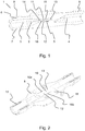
- a miniaturised fluid flow regulating device 1 is shown, cut in half.
- the device comprises a fluid flow channel 2 with an inlet portion 3, an outlet portion 4 and a flow regulation passage 5 between the inlet portion and the outlet portion.
- the device is assembled by a first 6 and a second 7 part of material, forming a housing of the device.
- the material may e.g. be a polymer material.
- the device may comprise a first 8 and second 9 connector for connecting the device to e.g. tubing.
- the flow regulating device comprises an elongated beam element 10 arranged in the flow channel 2 having the direction of elongation along the fluid flow channel.
- the elongated beam has a first end portion 13 and a second end portion 14 and extends between the inlet portion to the outlet portion of the flow channel.
- the elongated beam comprises a first 11 and a second 12 face.
- the second face 12 of the elongated beam defines a wall in the flow regulation passage.
- the first end portion 13 of the beam is clamped in the device, e.g. by integrally forming the elongated beam in the same piece of material as the device itself or by rigid attachment to the material of the device.
- the second end portion 14 of the beam not supported, forming a free end.
- the beam is formed as a cantilever.
- a fluid space 15 is formed in the device communicating with the inlet portion of the fluid flow channel.
- the first face 11 of the elongated beam defines a wall in the fluid space. The fluid space is further delimited by the attachment of the first end 13 of the elongated beam.
- Fig. 2 the first part of material 6 forming part of the fluid regulating device is shown.
- the elongated beam 10 is now shown with the second face 12 facing the viewer.
- the elongated beam is supported in the device by being integrally formed in the same piece of material as the first part 6.
- the lateral sides of the beam (perpendicular to the elongation of the beam) are free to move, and thus slits 16a and 16b are formed along the sides of the elongated beam.
- These slits provides for a controlled but minimised leakage flow from the fluid space into the flow channel and towards the outlet portion of the flow channel. This leakage flow may be limited by designing the slits and e.g. by providing a ridge under and/or over the elongated beam to increase the pressure drop over the slits.
- the first part of material 6 may be provided with protrusions 17 and/or indentions 18 to provide alignment and tight fitting of the first and second parts of material.
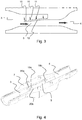
- Fig. 3 further shows the fluid regulating function of the device.
- the inlet portion 3, outlet portion 4 and flow regulation passage 5 of the flow channel is shown. From this drawing it is evident that the fluid space 15 is arranged such that the first face 11 of the beam 10 is subjected to fluid pressure communicating with the inlet portion 3 of the fluid flow channel.
- a pressure difference acting on the first 11 and second 12 face of the elongated beam causes the beam element to bend and regulate fluid flow in the flow regulation passage.
- a higher pressure in the inlet portion (and thus the fluid space 15) than in the flow regulation passage 5 causes the elongated beam to bend towards the flow regulation passage to decrease the cross-sectional area of the flow regulation passage. Thereby the flow resistance in the flow regulation passage is increased, limiting the flow speed of the fluid passing the flow regulation passage.
- FIG. 4 an embodiment of a miniaturised fluid flow regulating device is shown.
- the configuration and support of the elongated beam is shown.
- Fig. 4 shows a part 7 of the device with an inlet portion 3, an outlet portion 4 and a flow regulation passage 5 between the inlet portion and the outlet portion.
- the supporting means comprises a first 19a and a second 19b discrete support arranged in the middle of the flow channel, towards the inlet and outlet portion respectively.
- the supporting means comprises a first 20a and a second 20b ridge arranged along each side of the flow channel, to provide support along the lateral sides of the elongated beam.
- the ridges are also formed to limit the leak flow through slits formed between the elongated beam and lateral walls of the flow channel.
- the ridge supports may be provided with a shape that provides support along the elongated beam upon deflection of the beam.
- the shape of the ridge may be such that the support position along the beam is continuously dependent on the deflection of the beam thereby effectively shortening the unsupported length of the elongated beam upon increasing deflection of the beam. This has the effect to stiffening the beam gradually (or stepwise) upon deflection.
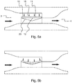
- Fig 5a and 5b the operation of the device is shown.
- the fluid space 15 is arranged such that the first face 11 of the beam 10 is subjected to fluid pressure communicating with the inlet portion of the fluid flow channel.
- the elongated beam is simply supported on the supporting means comprising a ridge 20.
- a pressure difference acting on the first 11 and second 12 face of the elongated beam causes the beam element to bend and regulate fluid flow in the flow regulation passage.
- the ridge is V-shaped. This has the effect that the elongated beam initially is simply supported at the first and second end portion until the deflection of the beam is such that they tangent the V-shaped support (as shown in Fig. 5b ). Thereafter any further deflection will result in the position of the support being moved towards the center of the V-shaped ridge. By moving the position of the support towards the center of the V-shaped ridge the effective length of the deflected beam will decrease, thereby increasing the stiffness of the beam.
- the shape of the supporting means may thus be adapted to provide an increasing stiffness upon deflection, thus adapting the flow regulation in the flow regulation passage to a desired pressure-flow behavior.
- the supporting means may be in the form of a ridge having a V-shape, a gull-wing shape, a curved shape, a sinusoidal shape etc, or in the form of distributed discrete supports of different heights adapted to provide support upon increasing deflection.
- the material of the beam may be selected to a material other than the material of the parts forming a housing, e.g. single crystalline silicon, metal etc.
- the material is preferably selected from a group of materials having a high fatigue strength.
- the device comprises a cantilever that constitutes one of the walls in the flow regulation channel, as can be seen in Fig. 1 .
- a pressure is applied at the inlet, the inlet pressure will act along the full length of the first face of the cantilever.
- a flow in the narrow flow regulation channel beneath the cantilever will result in a pressure drop resulting in a net force distribution along the length of the cantilever, causing it to bend down and restrict the flow in the channel, as can be seen in Fig. 3 .
- the spring force of the cantilever (the elongated beam) effectively balances against the flow induced downward bending forces acting on it, resulting in a predictable deflection at any inlet pressure.
- a leak flow occurs which may be utilized to avoid too much flow restriction.
- the total pressure drop in the device may be approximated and divided into three regions: a sudden contraction region where the flow meets the tip of the cantilever, a diffuser region along the length of the cantilever and a sudden expansion region at the exit, as shown Fig. 3 .
- ⁇ c p B 1 ⁇ C B 2 p
- B 1.4 ⁇ C p ⁇ 2
- a o 2 C L 4 ⁇ 21 ⁇ 4 C p 20 Eb 2 t 3 h 0 3
- L is the length of the cantilever
- E is the elastic modulus
- b and t are the width and thickness of the cantilever, respectively
- h 0 is the channel height at zero cantilever deflection.
Landscapes
- Health & Medical Sciences (AREA)
- Life Sciences & Earth Sciences (AREA)
- Engineering & Computer Science (AREA)
- Physics & Mathematics (AREA)
- Automation & Control Theory (AREA)
- General Physics & Mathematics (AREA)
- Medical Informatics (AREA)
- Animal Behavior & Ethology (AREA)
- Biomedical Technology (AREA)
- Heart & Thoracic Surgery (AREA)
- Biophysics (AREA)
- Molecular Biology (AREA)
- Surgery (AREA)
- Pathology (AREA)
- General Health & Medical Sciences (AREA)
- Public Health (AREA)
- Veterinary Medicine (AREA)
- Pulmonology (AREA)
- Physiology (AREA)
- Measuring Volume Flow (AREA)
- Sampling And Sample Adjustment (AREA)
- Investigating Or Analysing Biological Materials (AREA)
Claims (15)
- Miniaturisierte Fluidstrom-Regulierungsvorrichtung (1) zum Regulieren eines Stroms von ausgestoßenem Atem, um den Strom in dem Bereich von 10 bis 300 ml/s zu halten, wobei die Vorrichtung einen Fluidstromkanal (2) mit einem Einlassabschnitt (3), einem Auslassabschnitt (4) und einem Stromregulierungsdurchgang (5) zwischen dem Einlassabschnitt und dem Auslassabschnitt umfasst, wobei der Durchgang eine Querschnittsfläche aufweist, wobei ein längliches Balkenelement (10) derart in dem Stromkanal angeordnet ist, dass ein Druckunterschied über den Einlassabschnitt und den Auslassabschnitt bewirkt, dass das Balkenelement auslenkt und die Querschnittsfläche des Stromregulierungsdurchgangs verringert und dadurch den Fluidstrom in dem Stromregulierungsdurchgang reguliert,
dadurch gekennzeichnet, dass
der längliche Balken einen ersten Endabschnitt (13) und einen zweiten Endabschnitt (14) aufweist und sich von dem Einlassabschnitt bis zu dem Auslassabschnitt des Stromkanals erstreckt,
der längliche Balken einen Fluidraum (15) definiert, der mit dem Einlassabschnitt (3) in Verbindung steht und durch die Befestigung des ersten Endabschnitts begrenzt wird,
die Vorrichtung Stützmittel (19a, 19b, 20a, 20b) umfasst,
wenigstens einer von dem ersten und dem zweiten Endabschnitt in der Vorrichtung durch die Stützmittel gestützt wird und
die Stützmittel mit der Auslenkung des Balkens zusammenwirken, um die Querschnittsfläche des Stromregulierungsdurchgangs zu verringern, um den Strom zu regulieren. - Miniaturisierte Fluidstrom-Regulierungsvorrichtung nach Anspruch 1, dadurch gekennzeichnet, dass der erste Endabschnitt des länglichen Balkens in der Vorrichtung gestützt wird, und wobei der erste Endabschnitt des länglichen Balkens vorzugsweise zu dem Auslassabschnitt des Fluidstromkanals hin gerichtet ist.
- Miniaturisierte Fluidstrom-Regulierungsvorrichtung nach Anspruch 2, dadurch gekennzeichnet, dass der erste Endabschnitt in der Vorrichtung festgeklemmt ist, wodurch der längliche Balken einen Ausleger bildet.
- Miniaturisierte Fluidstrom-Regulierungsvorrichtung nach einem der Ansprüche 1 bis 3, dadurch gekennzeichnet, dass der zweite Endabschnitt frei ist.
- Miniaturisierte Fluidstrom-Regulierungsvorrichtung nach einem der Ansprüche 1 bis 2, dadurch gekennzeichnet, dass der zweite Endabschnitt in der Vorrichtung gestützt wird.
- Miniaturisierte Fluidstrom-Regulierungsvorrichtung nach einem der Ansprüche 1 bis 5, dadurch gekennzeichnet, dass die Stützmittel dafür konfiguriert sind, eine Stütze entlang der gesamten Länge des/der gestützten Endabschnitte(s), an einer Zwischenposition entlang der Länge des/der gestützten Endabschnitte(s) und/oder an den Ecken des/der Endabschnitte(s) bereitzustellen.
- Miniaturisierte Fluidstrom-Regulierungsvorrichtung nach einem der Ansprüche 1 bis 5, dadurch gekennzeichnet, dass die Stützmittel dafür konfiguriert sind, eine Stütze entlang des länglichen Balkens bereitzustellen, wobei eine Stützposition entlang des Balkens abhängig ist von der Auslenkung des Balkens.
- Miniaturisierte Fluidstrom-Regulierungsvorrichtung nach Anspruch 7, dadurch gekennzeichnet, dass die Stützposition entlang des Balkens kontinuierlich abhängig ist von dem Auslenkungsgrad des Balkens.
- Miniaturisierte Fluidstrom-Regulierungsvorrichtung nach Anspruch 7 oder 8, dadurch gekennzeichnet, dass die Stützmittel derart konfiguriert sind, dass die Stütze des Balkens auf eine Auslenkung des Balkens hin zu dem Stromregulierungsdurchgang hin bewegt wird, wobei die Stützmittel dafür konfiguriert sind, die ungestützte Länge des länglichen Balkens auf ein Zunehmen der Auslenkung des Balkens hin wirksam zu verkürzen, wodurch der Balken versteift wird.
- Miniaturisierte Fluidstrom-Regulierungsvorrichtung nach einem der Ansprüche 7 bis 9, dadurch gekennzeichnet, dass die Stützmittel einen Steg (20a, 20b) umfassen, der sich entlang der Längsausdehnung des Balkens erstreckt.
- Miniaturisierte Fluidstrom-Regulierungsvorrichtung nach einem der Ansprüche 7 bis 10, dadurch gekennzeichnet, dass die Stützmittel eine oder mehrere getrennte Stützen (19a, 19b) umfassen.
- Miniaturisierte Fluidstrom-Regulierungsvorrichtung nach einem der Ansprüche 7 bis 11, dadurch gekennzeichnet, dass die Stützmittel einen ersten und einen zweiten Steg umfassen, die sich entlang der Längsausdehnung des Balkens erstrecken und an einer ersten und einer zweiten seitlichen Seite des Balkens angeordnet sind, und wobei der erste und der zweite Steg derart gekrümmt sind, dass die Position der Stütze entlang des länglichen Balkens des Balkens von den Stegen kontinuierlich abhängig ist von dem Auslenkungsgrad des Balkens.
- Atemanalysevorrichtung, die eine miniaturisierte Fluidstrom-Regulierungsvorrichtung nach einem der Ansprüche 1 bis 12 zum Aufrechterhalten eines Stroms von 50 ± 5 ml/s, über einen Druckbereich von 1000 Pa, umfasst.
- Atemanalysevorrichtung nach Anspruch 13, die einen Sensor zum Analysieren der Konzentration von Stickstoffmonoxid, NO, in ausgestoßenem Atem umfasst.
- Verwendung einer miniaturisierten Fluidstrom-Regulierungsvorrichtung nach einem der Ansprüche 1 bis 12 in einer Atemanalysevorrichtung zum Regulieren eines Stroms von ausgestoßenem Atem, um den Strom über einen Druckbereich von 1000 Pa in dem Bereich von 50 ± 5 ml/s zu halten.
Applications Claiming Priority (2)
| Application Number | Priority Date | Filing Date | Title |
|---|---|---|---|
| SE1450070 | 2014-01-24 | ||
| PCT/EP2015/051340 WO2015110572A1 (en) | 2014-01-24 | 2015-01-23 | Miniaturized fluid flow regulating device |
Publications (2)
| Publication Number | Publication Date |
|---|---|
| EP3096821A1 EP3096821A1 (de) | 2016-11-30 |
| EP3096821B1 true EP3096821B1 (de) | 2019-11-13 |
Family
ID=52432805
Family Applications (1)
| Application Number | Title | Priority Date | Filing Date |
|---|---|---|---|
| EP15701518.1A Active EP3096821B1 (de) | 2014-01-24 | 2015-01-23 | Miniaturisierter flüssigkeitsströmungsregler |
Country Status (8)
| Country | Link |
|---|---|
| US (1) | US10433766B2 (de) |
| EP (1) | EP3096821B1 (de) |
| JP (1) | JP6556739B2 (de) |
| CN (1) | CN105916538B (de) |
| AU (1) | AU2015208121A1 (de) |
| CA (1) | CA2936462A1 (de) |
| ES (1) | ES2759275T3 (de) |
| WO (1) | WO2015110572A1 (de) |
Families Citing this family (7)
| Publication number | Priority date | Publication date | Assignee | Title |
|---|---|---|---|---|
| EP3393564B1 (de) * | 2015-12-21 | 2021-09-15 | Kindeva Drug Delivery L.P. | Durchflussregler zur verwendung in medizinischen inhalatoren |
| CN109288524B (zh) * | 2018-03-02 | 2021-05-18 | 微动互联(北京)科技有限公司 | 便携式鼻气流采集监测装置 |
| CN112533657B (zh) * | 2018-06-01 | 2024-12-17 | 安全袋瓣面罩公司 | 用于袋阀式面罩的压力安全装置 |
| US12543970B2 (en) | 2018-07-14 | 2026-02-10 | Arte Medical Technologies Ltd | Respiratory diagnostic tool and method |
| US12138081B2 (en) * | 2019-06-17 | 2024-11-12 | Caire Diagnostics Inc. | Asthma management system and method |
| US11119515B2 (en) * | 2019-11-07 | 2021-09-14 | GM Global Technology Operations LLC | Low profile pressure regulator |
| GB2616521B (en) * | 2020-12-22 | 2024-11-06 | Halliburton Energy Services Inc | Density constant flow device with flexible tube |
Family Cites Families (21)
| Publication number | Priority date | Publication date | Assignee | Title |
|---|---|---|---|---|
| US3057373A (en) * | 1959-10-19 | 1962-10-09 | Parker Hannifin Corp | Flow limiting valve |
| US3523559A (en) * | 1968-05-17 | 1970-08-11 | Crane Co | Fluid flow control device |
| US3646970A (en) * | 1970-06-01 | 1972-03-07 | Qualitrol Corp | Flow control unit for bellows controlled sudden pressure rise relay |
| US4230149A (en) | 1978-05-22 | 1980-10-28 | Eaton Corporation | Fluid flow regulating valve and system |
| US4253491A (en) * | 1980-02-25 | 1981-03-03 | Eaton Corporation | Fluid flow regulating valve and system |
| US5163920A (en) | 1991-01-30 | 1992-11-17 | Infusaid Inc. | Flow regulator damper element |
| US5582210A (en) * | 1992-09-21 | 1996-12-10 | Proprietary Technology, Inc. | Spring metal flow control apparatus |
| JP3545764B2 (ja) * | 1993-08-18 | 2004-07-21 | フアイソンズ・ピーエルシー | 吸息率制御器を備えた吸入装置 |
| US5906203A (en) * | 1994-08-01 | 1999-05-25 | Safety Equipment Sweden Ab | Breathing apparatus |
| US5941501A (en) * | 1996-09-06 | 1999-08-24 | Xerox Corporation | Passively addressable cantilever valves |
| US5970801A (en) * | 1997-12-30 | 1999-10-26 | Bear Medical Systems, Inc. | Variable orifice flow sensor |
| WO2002097865A2 (en) * | 2001-05-31 | 2002-12-05 | Rochester Institute Of Technology | Fluidic valves, agitators, and pumps and methods thereof |
| EP1841994A4 (de) | 2005-01-25 | 2012-11-14 | Aerocrine Ab | Konstantfluss-regulatorvorrichtung |
| US7481244B2 (en) * | 2006-06-05 | 2009-01-27 | Bioquiddity, Inc. | Fluid flow control device |
| CA2658095A1 (en) | 2006-08-01 | 2008-02-07 | Aradigm Corporation | Fluid flow regulating device |
| DK2210157T3 (da) * | 2007-11-15 | 2013-04-08 | Belimo Holding Ag | Gennemstrømningsbegrænser |
| FR2947887B1 (fr) * | 2009-07-10 | 2011-07-29 | Aldes Aeraulique | Conduit de section generale circulaire, equipe d?un dispositif de regulation du debit d?air |
| CN104379204A (zh) * | 2012-02-15 | 2015-02-25 | 费雪派克医疗保健有限公司 | 用于供应气体的系统、设备以及方法 |
| US8998838B2 (en) * | 2012-03-29 | 2015-04-07 | Alcon Research, Ltd. | Adjustable valve for IOP control with reed valve |
| JP6788503B2 (ja) * | 2014-03-20 | 2020-11-25 | キャップニア, インコーポレイテッド | 呼息中の一酸化窒素レベルを分析するための装置および方法 |
| US9752692B2 (en) * | 2016-01-13 | 2017-09-05 | Mueller International, Llc | Check valve with accelerated closure |
-
2015
- 2015-01-23 EP EP15701518.1A patent/EP3096821B1/de active Active
- 2015-01-23 CN CN201580004733.5A patent/CN105916538B/zh active Active
- 2015-01-23 AU AU2015208121A patent/AU2015208121A1/en not_active Abandoned
- 2015-01-23 WO PCT/EP2015/051340 patent/WO2015110572A1/en not_active Ceased
- 2015-01-23 CA CA2936462A patent/CA2936462A1/en not_active Abandoned
- 2015-01-23 US US15/111,888 patent/US10433766B2/en active Active
- 2015-01-23 ES ES15701518T patent/ES2759275T3/es active Active
- 2015-01-23 JP JP2016548173A patent/JP6556739B2/ja active Active
Non-Patent Citations (1)
| Title |
|---|
| None * |
Also Published As
| Publication number | Publication date |
|---|---|
| WO2015110572A1 (en) | 2015-07-30 |
| CN105916538B (zh) | 2019-12-13 |
| CN105916538A (zh) | 2016-08-31 |
| AU2015208121A1 (en) | 2016-07-21 |
| EP3096821A1 (de) | 2016-11-30 |
| CA2936462A1 (en) | 2015-07-30 |
| JP2017508953A (ja) | 2017-03-30 |
| US20160338619A1 (en) | 2016-11-24 |
| JP6556739B2 (ja) | 2019-08-07 |
| ES2759275T3 (es) | 2020-05-08 |
| US10433766B2 (en) | 2019-10-08 |
Similar Documents
| Publication | Publication Date | Title |
|---|---|---|
| US10433766B2 (en) | Miniaturized fluid flow regulating device | |
| EP2270441B1 (de) | Durchflussmesser | |
| CN105722558B (zh) | 具有非圆形的质心安装的呼气阀的呼吸器 | |
| US5038621A (en) | Variable area obstruction gas flow meter | |
| US4989456A (en) | Variable area obstruction gas flow meter | |
| CN104245051B (zh) | 带有多孔界膜的载气头盔 | |
| US8806955B2 (en) | Fluid flow conditioner | |
| KR101616662B1 (ko) | 초음파 유체 측정 장치 | |
| EP3316778B1 (de) | Vorrichtung zum auffangen von partikeln in ausatemluftstrom | |
| AU2006245224B2 (en) | Flow rate measuring device | |
| US7270143B2 (en) | Offset variable-orifice flow sensor | |
| JP4693905B2 (ja) | 流れシステム及び流れシステムを備えたマイクロ流体システム | |
| US20130116940A1 (en) | Flow sensor assemblies | |
| JP2018515194A (ja) | 低流量制御装置 | |
| CN111989633B (zh) | 流量调节器 | |
| CN107427654B (zh) | 流动构件 | |
| JP2023501701A (ja) | 方向調整機構を有するヘッドギア | |
| US10161772B1 (en) | Variable orifice flow sensor | |
| US9700235B2 (en) | Peak expiratory flow rate measurement apparatus | |
| KR20230065168A (ko) | 유량 맥동 조절 탄성 댐퍼, 이의 제조 방법 및 유량 맥동 저감 방법 | |
| EP2022717A2 (de) | Durchflussregelventil | |
| JP2002257614A (ja) | ガスメータ用の圧力変動緩和装置 | |
| Johansson et al. | A novel constant flow regulation principle for compact breath diagnostics | |
| Van Hirtum et al. | In-vitro study of pharyngeal pressure losses at the origin of obstructive sleep apnea |
Legal Events
| Date | Code | Title | Description |
|---|---|---|---|
| PUAI | Public reference made under article 153(3) epc to a published international application that has entered the european phase |
Free format text: ORIGINAL CODE: 0009012 |
|
| 17P | Request for examination filed |
Effective date: 20160714 |
|
| AK | Designated contracting states |
Kind code of ref document: A1 Designated state(s): AL AT BE BG CH CY CZ DE DK EE ES FI FR GB GR HR HU IE IS IT LI LT LU LV MC MK MT NL NO PL PT RO RS SE SI SK SM TR |
|
| AX | Request for extension of the european patent |
Extension state: BA ME |
|
| DAX | Request for extension of the european patent (deleted) | ||
| RAP1 | Party data changed (applicant data changed or rights of an application transferred) |
Owner name: CIRCASSIA AB |
|
| STAA | Information on the status of an ep patent application or granted ep patent |
Free format text: STATUS: EXAMINATION IS IN PROGRESS |
|
| 17Q | First examination report despatched |
Effective date: 20180926 |
|
| REG | Reference to a national code |
Ref country code: DE Ref legal event code: R079 Ref document number: 602015041562 Country of ref document: DE Free format text: PREVIOUS MAIN CLASS: A61M0015000000 Ipc: A61B0005080000 |
|
| GRAP | Despatch of communication of intention to grant a patent |
Free format text: ORIGINAL CODE: EPIDOSNIGR1 |
|
| STAA | Information on the status of an ep patent application or granted ep patent |
Free format text: STATUS: GRANT OF PATENT IS INTENDED |
|
| RIC1 | Information provided on ipc code assigned before grant |
Ipc: A61B 5/08 20060101AFI20190507BHEP Ipc: G05D 7/01 20060101ALI20190507BHEP |
|
| INTG | Intention to grant announced |
Effective date: 20190531 |
|
| GRAS | Grant fee paid |
Free format text: ORIGINAL CODE: EPIDOSNIGR3 |
|
| GRAA | (expected) grant |
Free format text: ORIGINAL CODE: 0009210 |
|
| STAA | Information on the status of an ep patent application or granted ep patent |
Free format text: STATUS: THE PATENT HAS BEEN GRANTED |
|
| AK | Designated contracting states |
Kind code of ref document: B1 Designated state(s): AL AT BE BG CH CY CZ DE DK EE ES FI FR GB GR HR HU IE IS IT LI LT LU LV MC MK MT NL NO PL PT RO RS SE SI SK SM TR |
|
| RIN1 | Information on inventor provided before grant (corrected) |
Inventor name: JOHANSSON, STAFFAN Inventor name: STEMME, GOERAN Inventor name: ROXHED, NICLAS |
|
| REG | Reference to a national code |
Ref country code: CH Ref legal event code: EP Ref country code: AT Ref legal event code: REF Ref document number: 1200835 Country of ref document: AT Kind code of ref document: T Effective date: 20191115 |
|
| REG | Reference to a national code |
Ref country code: DE Ref legal event code: R096 Ref document number: 602015041562 Country of ref document: DE |
|
| REG | Reference to a national code |
Ref country code: IE Ref legal event code: FG4D |
|
| REG | Reference to a national code |
Ref country code: NL Ref legal event code: MP Effective date: 20191113 |
|
| REG | Reference to a national code |
Ref country code: LT Ref legal event code: MG4D |
|
| PG25 | Lapsed in a contracting state [announced via postgrant information from national office to epo] |
Ref country code: PT Free format text: LAPSE BECAUSE OF FAILURE TO SUBMIT A TRANSLATION OF THE DESCRIPTION OR TO PAY THE FEE WITHIN THE PRESCRIBED TIME-LIMIT Effective date: 20200313 Ref country code: SE Free format text: LAPSE BECAUSE OF FAILURE TO SUBMIT A TRANSLATION OF THE DESCRIPTION OR TO PAY THE FEE WITHIN THE PRESCRIBED TIME-LIMIT Effective date: 20191113 Ref country code: LV Free format text: LAPSE BECAUSE OF FAILURE TO SUBMIT A TRANSLATION OF THE DESCRIPTION OR TO PAY THE FEE WITHIN THE PRESCRIBED TIME-LIMIT Effective date: 20191113 Ref country code: GR Free format text: LAPSE BECAUSE OF FAILURE TO SUBMIT A TRANSLATION OF THE DESCRIPTION OR TO PAY THE FEE WITHIN THE PRESCRIBED TIME-LIMIT Effective date: 20200214 Ref country code: BG Free format text: LAPSE BECAUSE OF FAILURE TO SUBMIT A TRANSLATION OF THE DESCRIPTION OR TO PAY THE FEE WITHIN THE PRESCRIBED TIME-LIMIT Effective date: 20200213 Ref country code: FI Free format text: LAPSE BECAUSE OF FAILURE TO SUBMIT A TRANSLATION OF THE DESCRIPTION OR TO PAY THE FEE WITHIN THE PRESCRIBED TIME-LIMIT Effective date: 20191113 Ref country code: NO Free format text: LAPSE BECAUSE OF FAILURE TO SUBMIT A TRANSLATION OF THE DESCRIPTION OR TO PAY THE FEE WITHIN THE PRESCRIBED TIME-LIMIT Effective date: 20200213 Ref country code: NL Free format text: LAPSE BECAUSE OF FAILURE TO SUBMIT A TRANSLATION OF THE DESCRIPTION OR TO PAY THE FEE WITHIN THE PRESCRIBED TIME-LIMIT Effective date: 20191113 Ref country code: PL Free format text: LAPSE BECAUSE OF FAILURE TO SUBMIT A TRANSLATION OF THE DESCRIPTION OR TO PAY THE FEE WITHIN THE PRESCRIBED TIME-LIMIT Effective date: 20191113 Ref country code: LT Free format text: LAPSE BECAUSE OF FAILURE TO SUBMIT A TRANSLATION OF THE DESCRIPTION OR TO PAY THE FEE WITHIN THE PRESCRIBED TIME-LIMIT Effective date: 20191113 |
|
| REG | Reference to a national code |
Ref country code: ES Ref legal event code: FG2A Ref document number: 2759275 Country of ref document: ES Kind code of ref document: T3 Effective date: 20200508 |
|
| PG25 | Lapsed in a contracting state [announced via postgrant information from national office to epo] |
Ref country code: HR Free format text: LAPSE BECAUSE OF FAILURE TO SUBMIT A TRANSLATION OF THE DESCRIPTION OR TO PAY THE FEE WITHIN THE PRESCRIBED TIME-LIMIT Effective date: 20191113 Ref country code: IS Free format text: LAPSE BECAUSE OF FAILURE TO SUBMIT A TRANSLATION OF THE DESCRIPTION OR TO PAY THE FEE WITHIN THE PRESCRIBED TIME-LIMIT Effective date: 20200313 Ref country code: RS Free format text: LAPSE BECAUSE OF FAILURE TO SUBMIT A TRANSLATION OF THE DESCRIPTION OR TO PAY THE FEE WITHIN THE PRESCRIBED TIME-LIMIT Effective date: 20191113 |
|
| PG25 | Lapsed in a contracting state [announced via postgrant information from national office to epo] |
Ref country code: AL Free format text: LAPSE BECAUSE OF FAILURE TO SUBMIT A TRANSLATION OF THE DESCRIPTION OR TO PAY THE FEE WITHIN THE PRESCRIBED TIME-LIMIT Effective date: 20191113 |
|
| PG25 | Lapsed in a contracting state [announced via postgrant information from national office to epo] |
Ref country code: EE Free format text: LAPSE BECAUSE OF FAILURE TO SUBMIT A TRANSLATION OF THE DESCRIPTION OR TO PAY THE FEE WITHIN THE PRESCRIBED TIME-LIMIT Effective date: 20191113 Ref country code: CZ Free format text: LAPSE BECAUSE OF FAILURE TO SUBMIT A TRANSLATION OF THE DESCRIPTION OR TO PAY THE FEE WITHIN THE PRESCRIBED TIME-LIMIT Effective date: 20191113 Ref country code: RO Free format text: LAPSE BECAUSE OF FAILURE TO SUBMIT A TRANSLATION OF THE DESCRIPTION OR TO PAY THE FEE WITHIN THE PRESCRIBED TIME-LIMIT Effective date: 20191113 Ref country code: DK Free format text: LAPSE BECAUSE OF FAILURE TO SUBMIT A TRANSLATION OF THE DESCRIPTION OR TO PAY THE FEE WITHIN THE PRESCRIBED TIME-LIMIT Effective date: 20191113 |
|
| REG | Reference to a national code |
Ref country code: DE Ref legal event code: R097 Ref document number: 602015041562 Country of ref document: DE |
|
| REG | Reference to a national code |
Ref country code: AT Ref legal event code: MK05 Ref document number: 1200835 Country of ref document: AT Kind code of ref document: T Effective date: 20191113 |
|
| PG25 | Lapsed in a contracting state [announced via postgrant information from national office to epo] |
Ref country code: SM Free format text: LAPSE BECAUSE OF FAILURE TO SUBMIT A TRANSLATION OF THE DESCRIPTION OR TO PAY THE FEE WITHIN THE PRESCRIBED TIME-LIMIT Effective date: 20191113 Ref country code: MC Free format text: LAPSE BECAUSE OF FAILURE TO SUBMIT A TRANSLATION OF THE DESCRIPTION OR TO PAY THE FEE WITHIN THE PRESCRIBED TIME-LIMIT Effective date: 20191113 Ref country code: SK Free format text: LAPSE BECAUSE OF FAILURE TO SUBMIT A TRANSLATION OF THE DESCRIPTION OR TO PAY THE FEE WITHIN THE PRESCRIBED TIME-LIMIT Effective date: 20191113 |
|
| REG | Reference to a national code |
Ref country code: CH Ref legal event code: PL |
|
| PLBE | No opposition filed within time limit |
Free format text: ORIGINAL CODE: 0009261 |
|
| STAA | Information on the status of an ep patent application or granted ep patent |
Free format text: STATUS: NO OPPOSITION FILED WITHIN TIME LIMIT |
|
| REG | Reference to a national code |
Ref country code: BE Ref legal event code: MM Effective date: 20200131 |
|
| 26N | No opposition filed |
Effective date: 20200814 |
|
| PG25 | Lapsed in a contracting state [announced via postgrant information from national office to epo] |
Ref country code: LU Free format text: LAPSE BECAUSE OF NON-PAYMENT OF DUE FEES Effective date: 20200123 |
|
| PG25 | Lapsed in a contracting state [announced via postgrant information from national office to epo] |
Ref country code: LI Free format text: LAPSE BECAUSE OF NON-PAYMENT OF DUE FEES Effective date: 20200131 Ref country code: SI Free format text: LAPSE BECAUSE OF FAILURE TO SUBMIT A TRANSLATION OF THE DESCRIPTION OR TO PAY THE FEE WITHIN THE PRESCRIBED TIME-LIMIT Effective date: 20191113 Ref country code: CH Free format text: LAPSE BECAUSE OF NON-PAYMENT OF DUE FEES Effective date: 20200131 Ref country code: AT Free format text: LAPSE BECAUSE OF FAILURE TO SUBMIT A TRANSLATION OF THE DESCRIPTION OR TO PAY THE FEE WITHIN THE PRESCRIBED TIME-LIMIT Effective date: 20191113 Ref country code: BE Free format text: LAPSE BECAUSE OF NON-PAYMENT OF DUE FEES Effective date: 20200131 |
|
| PG25 | Lapsed in a contracting state [announced via postgrant information from national office to epo] |
Ref country code: IE Free format text: LAPSE BECAUSE OF NON-PAYMENT OF DUE FEES Effective date: 20200123 Ref country code: IT Free format text: LAPSE BECAUSE OF FAILURE TO SUBMIT A TRANSLATION OF THE DESCRIPTION OR TO PAY THE FEE WITHIN THE PRESCRIBED TIME-LIMIT Effective date: 20191113 |
|
| REG | Reference to a national code |
Ref country code: ES Ref legal event code: FD2A Effective date: 20210603 |
|
| PG25 | Lapsed in a contracting state [announced via postgrant information from national office to epo] |
Ref country code: ES Free format text: LAPSE BECAUSE OF NON-PAYMENT OF DUE FEES Effective date: 20200124 |
|
| PG25 | Lapsed in a contracting state [announced via postgrant information from national office to epo] |
Ref country code: TR Free format text: LAPSE BECAUSE OF FAILURE TO SUBMIT A TRANSLATION OF THE DESCRIPTION OR TO PAY THE FEE WITHIN THE PRESCRIBED TIME-LIMIT Effective date: 20191113 Ref country code: MT Free format text: LAPSE BECAUSE OF FAILURE TO SUBMIT A TRANSLATION OF THE DESCRIPTION OR TO PAY THE FEE WITHIN THE PRESCRIBED TIME-LIMIT Effective date: 20191113 Ref country code: CY Free format text: LAPSE BECAUSE OF FAILURE TO SUBMIT A TRANSLATION OF THE DESCRIPTION OR TO PAY THE FEE WITHIN THE PRESCRIBED TIME-LIMIT Effective date: 20191113 |
|
| PG25 | Lapsed in a contracting state [announced via postgrant information from national office to epo] |
Ref country code: MK Free format text: LAPSE BECAUSE OF FAILURE TO SUBMIT A TRANSLATION OF THE DESCRIPTION OR TO PAY THE FEE WITHIN THE PRESCRIBED TIME-LIMIT Effective date: 20191113 |
|
| P01 | Opt-out of the competence of the unified patent court (upc) registered |
Effective date: 20230324 |
|
| PGFP | Annual fee paid to national office [announced via postgrant information from national office to epo] |
Ref country code: GB Payment date: 20260121 Year of fee payment: 12 |
|
| PGFP | Annual fee paid to national office [announced via postgrant information from national office to epo] |
Ref country code: DE Payment date: 20260122 Year of fee payment: 12 |
|
| PGFP | Annual fee paid to national office [announced via postgrant information from national office to epo] |
Ref country code: FR Payment date: 20260120 Year of fee payment: 12 |