EP3096861B1 - Filtre remplaçable d'un dispositif de filtration et dispositif de filtration - Google Patents
Filtre remplaçable d'un dispositif de filtration et dispositif de filtration Download PDFInfo
- Publication number
- EP3096861B1 EP3096861B1 EP15703238.4A EP15703238A EP3096861B1 EP 3096861 B1 EP3096861 B1 EP 3096861B1 EP 15703238 A EP15703238 A EP 15703238A EP 3096861 B1 EP3096861 B1 EP 3096861B1
- Authority
- EP
- European Patent Office
- Prior art keywords
- filter
- seal
- radially
- respect
- sheet metal
- Prior art date
- Legal status (The legal status is an assumption and is not a legal conclusion. Google has not performed a legal analysis and makes no representation as to the accuracy of the status listed.)
- Not-in-force
Links
Images


Classifications
-
- B—PERFORMING OPERATIONS; TRANSPORTING
- B01—PHYSICAL OR CHEMICAL PROCESSES OR APPARATUS IN GENERAL
- B01D—SEPARATION
- B01D29/00—Filters with filtering elements stationary during filtration, e.g. pressure or suction filters, not covered by groups B01D24/00 - B01D27/00; Filtering elements therefor
- B01D29/96—Filters with filtering elements stationary during filtration, e.g. pressure or suction filters, not covered by groups B01D24/00 - B01D27/00; Filtering elements therefor in which the filtering elements are moved between filtering operations; Particular measures for removing or replacing the filtering elements; Transport systems for filters
-
- B—PERFORMING OPERATIONS; TRANSPORTING
- B01—PHYSICAL OR CHEMICAL PROCESSES OR APPARATUS IN GENERAL
- B01D—SEPARATION
- B01D35/00—Filtering devices having features not specifically covered by groups B01D24/00 - B01D33/00, or for applications not specifically covered by groups B01D24/00 - B01D33/00; Auxiliary devices for filtration; Filter housing constructions
- B01D35/30—Filter housing constructions
-
- B—PERFORMING OPERATIONS; TRANSPORTING
- B01—PHYSICAL OR CHEMICAL PROCESSES OR APPARATUS IN GENERAL
- B01D—SEPARATION
- B01D27/00—Cartridge filters of the throw-away type
- B01D27/08—Construction of the casing
-
- B—PERFORMING OPERATIONS; TRANSPORTING
- B01—PHYSICAL OR CHEMICAL PROCESSES OR APPARATUS IN GENERAL
- B01D—SEPARATION
- B01D35/00—Filtering devices having features not specifically covered by groups B01D24/00 - B01D33/00, or for applications not specifically covered by groups B01D24/00 - B01D33/00; Auxiliary devices for filtration; Filter housing constructions
- B01D35/005—Filters specially adapted for use in internal-combustion engine lubrication or fuel systems
-
- B—PERFORMING OPERATIONS; TRANSPORTING
- B01—PHYSICAL OR CHEMICAL PROCESSES OR APPARATUS IN GENERAL
- B01D—SEPARATION
- B01D2201/00—Details relating to filtering apparatus
- B01D2201/30—Filter housing constructions
- B01D2201/301—Details of removable closures, lids, caps, filter heads
- B01D2201/304—Seals or gaskets
-
- B—PERFORMING OPERATIONS; TRANSPORTING
- B01—PHYSICAL OR CHEMICAL PROCESSES OR APPARATUS IN GENERAL
- B01D—SEPARATION
- B01D2201/00—Details relating to filtering apparatus
- B01D2201/34—Seals or gaskets for filtering elements
- B01D2201/347—Radial sealings
-
- B—PERFORMING OPERATIONS; TRANSPORTING
- B01—PHYSICAL OR CHEMICAL PROCESSES OR APPARATUS IN GENERAL
- B01D—SEPARATION
- B01D2201/00—Details relating to filtering apparatus
- B01D2201/40—Special measures for connecting different parts of the filter
- B01D2201/4015—Bayonet connecting means
Definitions
- the invention relates to an easy-change filter, in particular a spin-on filter, a filter device for fluid, in particular liquid, in particular oil or fuel, in particular an internal combustion engine, in particular a motor vehicle.
- the invention further relates to a filter device for fluid, in particular liquid, in particular oil or fuel, in particular an internal combustion engine, in particular a motor vehicle, with at least one easy-change filter, in particular spin-on filter.
- a filter device with a filter head and a filter cartridge is known.
- the filter cartridge is attached to the filter head.
- the filter head comprises a plurality of outwardly directed ascending projections which form a first component of a bayonet-like connection.
- the rising protrusions cooperate with similar protrusions of the filter cartridge to secure the filter cartridge to the filter head.
- a sealing ring is arranged between the filter head and the filter cartridge.
- an exchangeable filter which has a circumferential outer seal on the end face for bearing against a filter surface on the radially inward facing sealing surface.
- the outer seal is arranged in a seal receptacle that is open radially outward.
- the invention has for its object to design a spin-on filter and a filter device of the type mentioned, in which a realization of a connection between the spin-on filter and a filter head, in particular a realization of a seal on the spin-on filter, can be simplified and / or improved. In particular, a tightness of the assembled filter device to the environment is to be improved.
- the easy-change filter at least one filter element is arranged in the housing pot of the filter housing.
- the easy-change filter is completely replaced with the filter housing and the at least one filter element contained therein.
- Such spin-on filters can be designed as spin-on filters, spin-on filters, in particular screw-on filters.
- the at least one filter element can advantageously be arranged fixedly in the filter housing.
- at least one filter element can be exchangeably arranged in the filter housing.
- the easy-change filter can be easily detachably attached to the filter head with the connection device.
- the sheet metal part has at least one seal receiving groove for receiving at least one seal, in particular an outer seal that seals off from the surroundings.
- the at least one seal is received in the at least one seal receiving groove of the sheet metal part.
- the sheet metal part in turn, is connected to the front edge of the housing pot by means of the shaped flange. In this way, the at least one seal can be captively attached to the side of the easy-change filter.
- the at least one seal receiving groove and the corresponding seal can advantageously be arranged in the vicinity of the peripheral wall, in particular the outer wall, of the housing pot. In this way, the cross sections of areas radially inside the seal through which the fluid to be cleaned can flow can be enlarged.
- At least one seal can advantageously seal radially and / or axially between the filter head and the easy-change filter with respect to the connecting axis.
- the flow cross sections can be further enlarged radially within the seal.
- a radially acting seal can also be arranged in a position-tolerant manner in the axial direction. In this way, in particular, operational positional tolerances between the at least one radially acting seal and the corresponding sealing surface can be better compensated.
- Operational positional tolerances can be caused in particular by vibrations and / or pressure pulsations during operation.
- At least one seal can advantageously seal only in the radial direction with respect to the connecting axis. In this way, any compression of the at least one seal can be essentially independent of a degree of closure of the connecting device. Mechanical stress on the seal can thus be reduced.
- the free cross-section for a fluid flow in particular in the area of the fluid space, can be restricted less than with conventional easy-change filters.
- any pressure losses between the raw fluid side and the pure fluid side can be reduced.
- the easy-change filter according to the invention can be used in particular in filter devices, in particular pre-filters, in which a suction head of fluid pumps can be limited and / or outgassing and, in extreme cases, cavitation can also occur. In the case of such filter devices in particular, a pressure loss between the raw fluid side and the pure fluid side can be reduced with the easy-change filter according to the invention.
- the design of the at least one seal receiving groove allows great freedom of design in relation to the at least one seal used.
- a corresponding shape of the at least one seal receiving groove and / or a correspondingly suitable seal space can be selected.
- the at least one seal can advantageously have or be at least one sealing ring, in particular an O-ring seal.
- the at least one seal can have or be a differently shaped sealing ring, in particular with an angular and / or flat and / or high profile.
- At least one seal can also be designed as a flat (ring) seal.
- An O-ring seal has the advantage that it can simply slide along a corresponding radially inner and / or radially outer sealing surface during a plug-in movement in the direction of the connection axis. The radial sealing effect can be better defined and / or adjusted with the O-ring seal than with a flat (ring) seal.
- At least one seal can advantageously be at least partially elastic. In this way, the sealing function can be improved. In this way, the seal can also compensate for, in particular, production-related and / or operational tolerances and / or damping of operational-related vibrations.
- At least one seal can advantageously have at least one suitable holding means, in particular at least one holding lug, with which the seal can be held in the at least one seal receiving groove.
- At least one seal can advantageously bear radially on the outside on a corresponding surface, in particular a floor, of the corresponding at least one seal receiving groove with respect to the connection axis. Alternatively, it can also bear radially on the inside on a corresponding surface of the seal receiving groove.
- a bottom of the at least one seal receiving groove can advantageously serve as a radially acting counter bearing for the at least one seal, on which the seal can be supported.
- the sheet metal part can advantageously be formed from sheet metal by a deep-drawing process and / or hydroforming process or similar processes and / or a cold-forming process.
- the sheet metal part can be realized with an inner diameter that cannot be realized with other manufacturing methods, or at least is significantly more complex. Complex deformations radially on the inside, in particular seal receiving grooves that are open radially on the inside, can thus also be realized with the methods mentioned at the beginning.
- the sheet metal part can also be made from one piece, i.e. in one piece, with complex contours.
- the sheet metal formed part does not have to be composed of several parts, in particular welded or soldered, as is necessary for the production of complex contours, in particular undercuts, in manufacturing processes otherwise used in connection with exchangeable filters.
- the sheet metal part can advantageously be produced by a progressive tool according to the so-called hydroforming process.
- the sheet metal part can be manufactured with a relatively high degree of complexity due to its dimensions in a relatively small tool.
- deep drawing is defined as seamless and non-cutting metal forming.
- Thermoformed parts are produced by pressing a cut sheet into the desired shape using a die.
- a deep-drawing process can be used which is based on hydroforming or hydroforming.
- a cylindrical part in particular a metallic tube, can be formed in a closed mold by means of internal pressure.
- An internal pressure of up to 3000 bar and more can be built up in the mold, which also serves as a sealing device.
- This internal pressure presses the cylindrical part to be reshaped, in particular the round part, against the wall of the molding tool and thus forms the corresponding shapes. It is therefore also possible to realize undercuts, in particular radially open seal receiving grooves, in series production.
- the at least one filter-side connection part in particular with a thread and / or a connection element of a bayonet-type connection, is realized in connection with a separate cover component, in particular a housing cover.
- the thread is preferably a screw thread, in particular a single-start screw thread.
- the lid component is ring-shaped.
- the cover component has an annular disk section.
- the at least one filter-side connecting part is connected in one piece to the annular disk section.
- the cover component can advantageously have at least one front opening, in particular a push-through opening for a connection cylinder.
- the connection cylinder can advantageously at least also realize a central central opening and / or at least one fluid opening offset radially outward.
- the at least one filter-side connecting part, in particular the cover component can advantageously be molded in particular from plastic, in particular (injection-molded).
- the cover component is designed to close, in particular to at least partially close the housing of the easy-change filter.
- the connecting part on the filter side is connected in one piece to the cover component. In this way, an outlay on components can be reduced.
- both the separate cover component and at least one seal can be held on the housing pot.
- the at least one sheet metal part and at least one filter-side connection part can be movable relative to one another within a predeterminable play. In this way, component-related and / or assembly-related and / or operational-related position tolerances can be better compensated for.
- a shaped flange, in particular a flange can be realized using a forming and connection method in which the edges of the cylindrical parts to be connected, in particular the sheet metal part and the edge of the housing pot, are bent open. The material can be compressed. The edge areas of the parts to be connected are bent around one another, in particular folded. In this way, a tight connection between the parts can be realized.
- the parts to be connected can be bent radially around one another with respect to the connection axis. Alternatively, they can also be bent radially inwards. Combinations of bends radially outward and radially inward can also be made.
- At least one sealant or sealing material can additionally be arranged between the edge regions of the parts to be crimped before, during or after the shaping process. In this way, the tightness of the flare connection can be further improved.
- a stable connection between the at least one seal receiving groove - and thus the at least one seal - and the connection body can be realized by the form flare.
- the sheet metal part can easily be combined with common components, in particular housing pots and / or filter-side connecting parts and / or cover components, in particular housing cover. Such a combination can be easily implemented.
- the filter device in particular the easy-change filter, can advantageously be designed in such a way that the unfiltered fluid is fed in on one end face and the filtered fluid is discharged on the same end face.
- at least one inlet, in particular an inlet, and at least one outlet, in particular at least one outlet, can be arranged on the same end face of the easy-change filter.
- a central central opening can advantageously be a fluid outlet opening through which cleaned fluid can get out of the easy-change filter.
- At least one fluid opening that is offset radially outward with respect to the central central opening and / or with respect to the connecting axis can accordingly be a fluid inlet opening through which the fluid to be cleaned can get into the easy-change filter.
- the central central opening can be a fluid inlet opening
- the at least one offset fluid opening can be a fluid outlet opening.
- the central opening can be designed such that both the raw fluid and the pure fluid can flow through them into the easy-change filter or out of the easy-change filter.
- At least one seal receiving groove in particular at least one seal, can be arranged on the side of the shaped flange that faces axially towards the pot bottom of the housing pot.
- the at least one seal can be arranged protected inside the housing pot.
- an axial installation space of the easy-change filter can be reduced.
- At least one corresponding sealing face on the head side can be arranged on the side of the filter head, with which at least one seal, in particular the outer seal, can cooperate in a sealing manner.
- the at least one sealing surface can be located radially outside, inside and / or radially on the same width of the at least one seal.
- At least one head-side sealing surface can be implemented in connection with at least one head-side connecting part.
- at least one head-side sealing surface can be implemented on a radially outer and / or radially inner circumferential side and / or an end face of a hollow cylinder section.
- At least one head-side connecting part on a radially inner or radially outer peripheral side of a hollow cylindrical section can have at least one connecting element, in particular an internal thread / external thread and / or a connecting part of a bayonet-type connection.
- At least one head-side sealing surface can advantageously be arranged on a radially opposite side of a head-side connecting element of at least one head-side connecting part. In this way, radial forces, which act on the head-side connecting element when the replaceable filter is connected to the filter head, can be transmitted to the head-side sealing surface. In this way, a sealing function can be improved.
- the at least one seal in particular the outer seal, can advantageously be separated from the connecting parts, that is to say not directly connected to one of the connecting parts.
- the at least one seal and the connecting parts can each be optimized for their respective function.
- the at least one seal can be decoupled from mechanical forces which act on the connecting parts. Furthermore, any positional tolerances can be better compensated for.
- At least one further mechanical intermediate component namely an annular disk section of a housing cover, and a force transmission element of the easy-change filter are arranged between the shaped flange and the connecting parts.
- the at least one seal and the connecting parts are therefore separated by the at least one intermediate component.
- the at least one intermediate component can bring about mechanical decoupling between the at least one seal and at least one of the connecting parts.
- the at least one intermediate component can make it possible to increase the design freedom of both the connecting parts and the at least one seal.
- structural measures in particular to compensate for mechanical loads that act on the at least one seal, on the connecting parts and on the at least one intermediate component, and / or component-related or operational tolerances and / or operational vibrations can be improved separately from one another.
- the connecting parts can each be made from a single material or from a material mix.
- the connecting parts can advantageously be made of plastic, metal, in particular aluminum and / or sheet metal, or have such a material.
- the at least one connecting part on the head side and the at least one connecting part on the filter side can be made of the same material or different materials.
- the easy-change filter can advantageously have a round cross section.
- the easy-change filter can advantageously be coaxial with a filter axis.
- the filter axis can advantageously coincide with the connection axis. In this way, assembly can be simplified.
- the easy-change filter comprises at least one filter element.
- the filter element can advantageously have a circumferentially closed filter medium.
- the filter medium can advantageously be folded or bent in a star or zigzag shape.
- the filter medium can advantageously be tightly connected to at least one end face with an end body, in particular an end plate.
- the filter element can advantageously be coaxial with the filter axis.
- the filter element can advantageously have at least one support body.
- the support body can advantageously be a central tube.
- the support body can advantageously be located in an element interior of the filter element.
- the support body can extend between the end bodies.
- At least one end body can be axially supported on the at least one support body with respect to the filter axis. In this way, axially directed forces can be transmitted between the at least one end body and the at least one support body at least with respect to the connecting axis.
- the easy-change filter can additionally have at least one component of a separating device for separating water from the fluid, in particular fuel or oil.
- the easy-change filter can have at least one coalescing medium and / or at least one separating tube, in particular a strainer basket. The smallest water droplets contained in the fluid can be combined to form large water drops with the coalescing medium.
- the separating tube can have a peripheral wall with / made of a hydrophobic (sieve) material. The peripheral wall of the separating tube can be sieve-like at least in sections. The water drops can be retained on the peripheral wall and, depending on the density of the fluid to be cleaned, sink or rise in a corresponding upstream precipitation gap, depending on the density of the fluid to be cleaned.
- the fluid to be cleaned can flow through the peripheral wall of the separation tube.
- the separating tube can be connected at one end to a fluid outlet, in particular an outlet cylinder, of the easy-change filter. In this way, the water freed of fluid can get out of the separating tube through the fluid outlet.
- the outlet cylinder can easily be connected in terms of fluid technology to a corresponding connection piece of the filter head, in particular by plugging one into the other or one inside the other.
- the filter device in particular the easy-change filter element, is suitable for cleaning, in particular filtering, fluid.
- liquids in particular oil or fuel
- Operating fluids of the internal combustion engine can advantageously be cleaned with the filter device, in particular the easy-change filter element.
- the fluid can be filtered and dirt particles can be removed.
- water contained in the fluid can be separated.
- the filter device can be used in internal combustion engines of motor vehicles. It can also be used in other types of internal combustion engines, in particular industrial engines.
- the invention can also be used outside of internal combustion engines, in particular in automotive engineering.
- the filter device has a filter head on which a replaceable filter can be mounted.
- the filter head can have at least one inlet and / or at least one outlet for the fluid.
- the filter head can preferably be fixed firmly to a frame.
- the frame can in particular be part of the internal combustion engine and / or the motor vehicle.
- the filter head has at least one head-side connecting part of the connecting device for the easy-change filter.
- the easy-change filter has at least one filter-side connecting part of the connecting device. At least one head-side connection part can be detachably connected to at least one filter-side connection part.
- the connecting device can advantageously be closable and detachable by means of a combined plug-in movement and rotary movement (plug-in and / or rotary movement) with respect to the connection axis.
- Combined plug / turn connections can be closed and opened quickly and easily. They are also robust against tensile loads in the direction of the connection axis.
- a quick-release fastener can be easily realized, which can be closed and opened quickly and easily.
- a plug-in and / or rotatable connection can in particular be realized as a screw connection and / or a bayonet-type connection.
- the easy-change filter can be referred to as a spin-on filter or screw-on filter.
- the fluid-carrying spaces in particular spaces between the easy-change filter and the filter head and / or fluid openings, can be tightly separated from the surroundings.
- the at least one seal can be located on the raw side or the clean side of the filter element of the easy-change filter. This can depend on the direction of flow of the fluid through the easy-change filter.
- At least one seal receiving groove can be open radially inward with respect to the connecting axis and / or at least one seal receiving groove can be open radially outward.
- the at least one seal can be introduced into the at least one seal receiving groove from the open side.
- the at least one seal can protrude radially through the open side of the at least one seal receiving groove. With its protruding section, it can cooperate sealingly in the radial and / or axial direction with at least one corresponding sealing surface on the side of the filter head.
- the housing pot can be made of sheet metal at least in its edge region. In this way, the edge region of the housing pot can be easily and reliably connected to the sheet metal part by means of the molding flange.
- the entire housing pot can advantageously be made of sheet metal. In this way it can be realized easily and stably in one piece.
- the side of at least one seal receiving groove that is radially open with respect to the connection axis can be viewed radially with respect to the connection axis with respect to a connection side of at least one filter-side connection part, in particular a thread and / or a connection element of a bayonet-type connection, which is located with respect to the connection axis located on the same side.
- a corresponding head-side connection part can easily be arranged radially between the at least one seal and the at least one filter-side connection part.
- the at least one connecting part on the head side can thus be pressed against the at least one seal by means of the at least one connecting part on the filter side.
- a sealing effect can be further improved in this way.
- an annular filter-side connection part can be arranged radially within at least one seal receiving groove with respect to the connection axis.
- the at least one seal receiving groove can be open radially inwards.
- the annular filter-side connection part can be arranged radially outside of at least one seal receiving groove.
- the at least one seal receiving groove can be open radially outwards.
- the head-side connecting part can advantageously be realized as a hollow cylinder section or on a hollow cylinder section.
- a peripheral wall of the hollow cylinder section can advantageously be arranged at least partially radially with respect to the connection axis between the at least one seal and at least one filter-side connection part.
- a peripheral side of the hollow cylinder section can have at least one head-side connecting element.
- the other circumferential side can have at least one head-side sealing surface for at least one seal, in particular an outer seal.
- At least one force transmission element in particular a force transmission ring, is arranged axially force transmitting between at least one cover component on the one hand and the shaped flange on the other hand.
- An additional contour can be realized with the at least one power transmission element.
- the at least one force transmission element With the at least one force transmission element, axial forces can be absorbed by the filter element and transmitted to the form flare and thus kept away from the sheet metal part, in particular at least one seal receiving groove. A requirement for the mechanical stability of the sheet metal part can be reduced accordingly. In this way, relatively thin sheet metal can also be used to produce the sheet metal part.
- At least one cover component and / or at least one filter-side connecting part in particular parts made from injection molding, can be made simpler in this way.
- a stability of the support of the at least one cover component and / or the at least one filter-side connecting part against the housing, in particular the housing pot, can be increased with the at least one force transmission element.
- At least one force transmission element can advantageously be made of sheet metal.
- a wall thickness of the sheet of the at least one force transmission element can advantageously be greater than a wall thickness of the sheet metal part.
- At least one force transmission element can advantageously be equipped with support and / or stabilization structures. In this way, the mechanical stability, in particular with respect to the Connection axis can be improved in the axial direction. In order to achieve the same mechanical stability, in particular with regard to axial power transmission, thinner wall thicknesses can also be used. This saves material. This can have a positive effect both in terms of weight and space requirements.
- At least one force transmission element can advantageously have embossed structures. The embossed structures can extend at least axially.
- At least one force transmission element can be realized in one piece or in several pieces with at least one cover component, in particular a housing cover, and / or at least one filter-side connecting part. In this way, a production outlay and / or an assembly outlay and / or a component outlay can be reduced.
- at least one power transmission element can be implemented as an extension of at least one cover component and / or a filter-side connecting part.
- At least one power transmission element can be implemented separately from at least one cover component and / or at least one filter-side connecting part. In this way, the corresponding components can be implemented independently of one another, even from different materials.
- At least one power transmission element can advantageously be implemented as a power transmission ring.
- the force transmission ring in particular circumferential axial forces can be transmitted circumferentially with respect to the connecting axis.
- a receptacle for at least one power transmission element can be realized with respect to the connection axis radially between the sheet metal part and a peripheral wall of the housing pot.
- the at least one power transmission element can thus be arranged in a space-saving manner in the receptacle.
- the at least one force transmission element can run approximately parallel to at least a section of the sheet metal part with respect to an axial force transmission.
- the sheet metal formed part can have at least one securing element, in particular at least one securing tab, of an anti-rotation device, which can cooperate with at least one counter-securing element, in particular at least one securing receptacle, of the anti-rotation device on the part of at least one filter-side connecting part, in particular a cover component, in order to achieve a To limit, in particular to prevent, relative rotation between the sheet metal part and the at least one filter-side connecting part, in particular the cover component.
- At least one securing element can be realized on the sheet metal part as the protruding element, in particular as a tab, foot or pin.
- At least one securing element can be realized as an axial extension of the sheet metal part.
- At least one counter-fuse element on the side of at least one filter-side connecting part can be implemented as a recess or receptacle, in particular a hole or opening, into which at least one protruding fuse element can engage.
- At least one counter-securing element on the side of at least one filter-side connecting part can be realized as the protruding element and at least one corresponding securing element on the part of the sheet metal part as a recess or receptacle.
- the anti-rotation device can have a plurality of securing elements and counter-securing elements interacting in pairs. In this way, a more even force distribution can be achieved.
- the securing elements / counter-securing elements can advantageously be arranged circumferentially, in particular evenly distributed, with respect to the connecting axis.
- a torque can be transmitted from the housing pot via the shaped flange and the sheet metal formed part to the at least one filter-side connecting part, in particular the cover component.
- the at least one filter-side connecting part can be connected to or separated from the filter head by rotating the housing pot relative to the filter head.
- the securing elements / counter-securing elements can advantageously cooperate while maintaining a respective game. In this way, a position tolerance between the sheet metal part and the at least one filter-side connecting part, in particular the cover component, can be compensated for. Alternatively or additionally, securing elements / counter-securing elements can also interact without play.
- FIG 1 A filter system 10, for example for engine oil of an internal combustion engine of a motor vehicle, is shown in a longitudinal section.
- Figure 4 shows a detailed view of the filter system 10.
- the filter system 10 can alternatively also be used for another operating fluid, for example fuel, of an internal combustion engine.
- the filter system 10 comprises a filter head 12, to which an exchangeable filter 14 is detachably fastened.
- the filter head 12 is made of metal.
- the filter head 12 is fixedly connected to the internal combustion engine and serves as a connecting part for the easy-change filter 14.
- the filter head 12 comprises an inlet 16 and an outlet 18 for the engine oil.
- the inlet 16 and the outlet 18 are connected to corresponding oil lines of the internal combustion engine in a manner not of further interest here.
- the filter head 12 has a head-side connecting part 20 of a detachable connecting device, designated overall by 22, for connecting the replaceable filter 14 to the filter head 12.
- the head-side connecting part 20 is made of metal.
- the head-side connecting part 20 has the shape of a hollow cylinder section which is connected in one piece to the main part of the filter head 12.
- the head-side connecting part 20 is coaxial with a filter axis 24.
- the head-side connecting part 20 On its radially inner circumferential side, the head-side connecting part 20 has an internal thread as a connecting element.
- the radially outer peripheral side of the head-side connecting part 20 forms an outer sealing surface 25.
- the filter head 12 further comprises a coaxial cylindrical connecting piece 26, which is located radially within the head-side connecting part 20. An interior of the connecting piece 26 is connected to the outlet 18 of the filter head 12.
- the connecting piece 26 At its end axially facing the easy-change filter 14, the connecting piece 26 has a sealing surface 28 for an inner seal 30 on its radially inner peripheral side.
- the inner seal 30 is located radially on the outside at the end of a connecting cylinder 32 of a filter element 34 of the easy-change filter 14.
- the connecting piece 26 is placed on the connecting cylinder 32.
- the connecting piece 26 and the connecting cylinder 32 are surrounded radially on the outside by an inlet annular space 36.
- the inlet annulus 36 is formed between the filter head 12 and the easy-change filter 14.
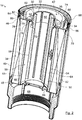
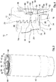
- the easy-change filter 14 which in Fig. 2 in detail and in Fig. 3 shown in longitudinal section is designed as a spin-on filter with a round cross-section. It is essentially coaxial to the filter axis 24.
- the easy-change filter 14 has a housing pot 40, in the open side of which a housing cover 42 is fastened.
- the filter element 34 designed as a round filter element is arranged coaxially in the housing pot 40.
- the filter element 34 has a filter medium 44 which is folded in a zigzag shape and is closed on the circumference.
- the filter medium 44 is in each case sealed on its end faces with a connecting end disk 46, in Fig. 1 and 2nd above, and a counter end plate 48, below.
- the connecting end disk 46 is located on the side of the filter element 34 facing the housing cover 42.
- the filter medium 44 surrounds an element interior 50 of the filter element 34.
- the element interior 50 is located on a downstream clean side of the filter medium 44
- the counter end plate 48 closes off the element interior 50 on the end face of the filter element 34 facing a pot bottom of the housing pot 40.
- the base of the pot is in a corresponding internal thread on the radially inner circumferential side of the housing pot 40, in Figure 1 and 2nd screwable from below. In Figures 1 and 2nd the bottom of the pot is not shown.
- the filter element 34 is axially sealed against a corresponding step of the housing pot 40 in a manner of no further interest, with the interposition of an annular seal.
- the filter element 34 is surrounded radially on the outside by an annular space 52 on the raw side, which is delimited by the radially inner circumferential side of the housing pot 40.
- a coaxial center tube 54 extends between the counter end plate 48 and the connecting end plate 46 in the interior 50 of the element.
- a peripheral wall of the center tube 54 has a plurality of through openings for engine oil.
- a coalescing medium 55 of a water separating device 56 is arranged between the radially inner peripheral side of the filter medium 44 and the radially outer peripheral side of the center tube 54.
- the smallest water droplets contained in the motor oil can be combined to form larger water drops with the coalescing medium 55.
- the connecting end disk 46 has a coaxial central opening through which a coaxial separating tube 58 of the water separating device 56 passes.
- the separating tube 58 forms the connecting cylinder 32.
- the separating tube 58 is open.
- the separating tube 58 is closed at its axially opposite end facing the counter end plate 48.
- the separating tube 58 is designed as a strainer basket.
- a peripheral wall of the separating tube 58 has a hydrophobic screen material that is permeable to engine oil.
- connection cylinder 32 defines a coaxial outlet opening 60 of the easy-change filter 14 for the cleaned engine oil.
- the outlet opening 60 forms a central oil drain channel.
- the connecting cylinder 32 has a coaxial sealing groove 62 for the inner seal 30.
- the inner seal 30 is designed as an O-ring seal. When the replaceable filter 14 is installed, the radially outer side of the inner seal 30 lies tightly against the sealing surface 28 of the connecting piece 26 of the head-side connecting part 20. The inner seal 30 has a sealing effect in the radial direction. The inner seal 30 tightly separates an upstream raw side of the filter element 34 radially outside the connecting cylinder 32, or the inlet annular space 36, from the clean side.
- the precipitation gap 64 is closed on its side facing the connecting end disk 46 with the latter and a collar of the separating tube 58 projecting radially outward.
- the counter end plate 48 points in Figure 2 shown water outlet openings 66, which connect the precipitation gap 64 with a water collection chamber 68.
- the water collecting space 68 is located between the pot bottom of the housing pot 40, which is not shown in the figures, and the counter end plate 48. The pot bottom can be unscrewed to drain off water collected in the water collecting space 68.
- the housing cover 42 is in detail in Figures 5 to 7 shown.
- the housing cover 42 is injection molded in one piece from plastic. It has a coaxial annular disk section 70.
- the annular disk section 70 has a coaxial push-through opening 72 for the connecting cylinder 32 of the filter element 34.
- a filter-side connecting part 74 of the connecting device 22 is connected in one piece to the annular disk section 70.
- the filter-side connecting part 74 has the shape of a round coaxial hollow cylinder.
- the filter-side connecting part 74 extends on the outside of the housing cover 42 axially facing away from the filter element 34 outer peripheral side, the filter-side connecting part 74 has an external thread as a connecting element that matches the internal thread of the head-side connecting part 20.
- the annular disk section 70 has a plurality of circular sector-like recesses on its inner side axially facing away from the filter-side connecting part 74.
- the recesses are distributed around the circumference and each extend in the radial direction.
- the cutouts form inlet channels 76 for the engine oil to be cleaned.
- the cutouts are axially continuously open and form inlet openings 78 of the inlet channels 76 there.
- the inlet channels 76 connect the inlet annular space 36 of the filter head 12 with the Annulus 52 of the housing pot 40.
- Radially extending ribs 79 between adjacent inlet channels 76 serve as spacers and are axially supported against the outside of the connecting end plate 46.
- a coaxial ring section defines the push-through opening 72 and connects the radially inner ends of the ribs 79.
- the cutouts are also axially continuously open and form slot-like securing receptacles 80 for circumferentially extending locking tabs 82 of an anti-rotation device 84 of a cover plate ring 86. Radially between the securing receptacles 80 and the inlet openings 78 the rear walls of the inlet channels 76 facing the outside of the housing cover 42 are closed.
- the cover plate ring 86 is shown in detail in Figures 8 and 9 shown.
- the cover plate ring 86 is formed from sheet metal. It has a multi-curved profile. With its radially outer circumferential side, it is firmly connected to a free edge of the housing pot 40 by means of a flange connection 88.
- the flange connection 88 is a shaped flange.
- the cover plate ring 86 serves as a holder for an outer seal 90 and the housing cover 42 on the housing pot 40. Radially inside the flange connection 88, the cover plate ring 86 is approximately coaxially circular-cylindrical. Viewed in the axial direction from the flange connection 88 in the direction of the pot bottom of the housing pot 40 behind the flange connection 88, the cover plate ring 86 has an annular collar which extends radially inwards. The ring collar delimits a seal receiving groove 92 on the axial side facing the flange connection 88.
- the seal receiving groove 92 has a U-shaped profile and is open radially inwards.
- a securing area with the securing tabs 82 of the anti-rotation device 84 adjoins the seal receptacle 92.
- the securing tabs 82 are distributed over the circumference. They each extend in the axial direction away from the seal receiving groove 92.
- the outer seal 90 is arranged in the seal receiving groove 92.
- the outer seal 90 is arranged below the side of the flange connection 88 facing the filter head 12, that is to say inside the housing pot 40.
- the outer seal 90 is an O-ring seal.
- the outer seal 90 is oriented radially inward with respect to the filter axis 24.
- the outer seal 90 acts in the radial direction.
- annular receptacle 94 for a power transmission ring 96.
- the annular receptacle 94 is open on its side facing away from the flange connection 88.
- the power transmission ring 96 is made of metal, for example bent sheet metal. It has a round hollow cylindrical section which is bent radially inward by approximately 90 ° on the side axially facing away from the flange connection 88. Overall, the force transmission ring 96 has an approximately J-shaped profile, the lower part of the "J" being directed radially inward.
- the force transmission ring 96 is supported axially in the region of the flange connection 88 on a radially inwardly curved shoulder of the peripheral wall of the housing pot 40. With its section bent radially inwards, the force transmission ring 96 is supported axially against the outside of the ring disk section 70 of the housing cover 42. In this way, an axial force between the housing cover 42 can be transmitted directly to the flange connection 88 and thus to the housing pot 40 by means of the force transmission ring 96, without the cover plate ring 86 being mechanically loaded.
- the seal receiving groove 92 with the outer seal 90 is located axially between the aforementioned two axial support points of the force transmission ring 96.
- the housing pot 40 is formed from sheet metal.
- the cover sheet metal ring 86 is formed from a piece of pipe made of sheet metal by means of a deep-drawing process in combination with a hydroforming process, so that the corresponding contour is created with the seal receiving groove 92.
- the power transmission ring 96 is made of metal, for example shaped and / or cast.
- the housing cover 42 with the filter-side connecting part 74, the external thread, the inlet channels 76 and the securing receptacles 80 is injection-molded in one piece from plastic or is produced as a sheet metal part.
- the filter element 34 is preassembled from the folded filter medium 44, the coalescing medium 55, the end plates 74 and 76, the center tube 54 and separating tube 58.
- the filter element 34 is inserted with the counter end plate 48 first, with the interposition of the ring seal axially to the filter axis 24 in the housing pot 40.
- the housing cover 42 is inserted with its inner side axially facing away from the filter-side connecting part 74 axially to the filter axis 24 into the open side of the housing pot 40, so that the connecting cylinder 32 of the separating tube 58 of the filter element 34 projects through the push-through opening 72 of the annular disk section 70.
- the force transmission ring 96 with its radially inwardly bent section is inserted axially to the filter axis 24 through the opening of the housing pot 40 and placed on the outside of the housing cover 42 facing away from the element interior 50.
- the cover plate ring 86 is inserted with the securing tabs 82 first axially through the opening of the housing pot 40 and placed on the outside of the housing cover 42, so that the securing tabs 82 each protrude through a securing receptacle 80 of the housing cover 42.
- the free edge of the housing pot 40 is then flanged radially outwards with the corresponding edge of the cover plate ring 86 with the interposition of sealing material, and the flanged connection 102 is thus realized.
- the easy-change filter 14 with the housing cover 42 is first moved axially to a connecting axis, which in the exemplary embodiment coincides with the filter axis 24, in a plug-in movement toward the head-side connecting part 20 of the filter head 12.
- the head-side connection part 20 is inserted into the free area between the filter-side connection part 74 and the cover plate ring 86, so that the internal thread of the head-side connection part 20 abuts the external thread of the filter-side connection part 74.
- the filter-side connecting part 74 With a rotary movement of the easy-change filter 14 in the closing direction of rotation, the filter-side connecting part 74 is screwed into the head-side connecting part 20.
- the outer sealing surface 25 of the head-side connecting part 20 slides along a radially inner sealing surface 98 of the outer seal 90.
- the outer seal 90 rests with its radially inner sealing surface 98 in a radially inward sealing manner on the outer sealing surface 25 of the head-side connecting part 20.
- the outer seal 90 seals the crude oil area, in particular the inlet annulus 36 and the inlet channels 76, from an environment 100.
- the inner seal 30 rests in a radially outward sealing manner on the sealing surface 28 of the connecting piece 26 of the filter head 12.
- the edge of the head-side connecting part 20 facing the easy-change filter 14 maintains an axial play with respect to the outside of the annular disk section 70 of the housing cover 42 facing it.
- engine oil to be cleaned is supplied to the inlet annular space 36 through the inlet 16 of the filter head 12.
- the flow of the engine oil in the filter system 10 is particularly in FIG Figures 1 , 4th , 5 and 6 indicated by curved arrows 102.
- the engine oil passes through the inlet channels 76 into the annular space 52 of the easy-change filter 14.
- the engine oil to be filtered flows through the filter medium 44 from radially outside to radially inside and is freed of particles.
- the smallest water droplets contained in the engine oil are combined to form large water drops in the coalescing medium 55.
- the engine oil with the water drops flows through the passage openings in the peripheral wall of the central tube 54 into the precipitation gap 64.
- the engine oil flows through the sieve-like, hydrophobic peripheral wall of the separating tube 58 and reaches its interior.
- the cleaned motor oil leaves the interior of the separating tube 58, that is to say also the element interior 50, through the outlet opening 60 and reaches the interior of the connecting piece 26. From there, the filtered and water-free engine oil flows into the outlet 18 of the filter head 12 and leaves it Filter system 10.
- the water drops are retained on the radially outer circumferential side of the separating tube 58, sink downward in the precipitation gap 64 due to gravity and pass through the water outlet openings 66 in the counter end plate 48 into the water collecting chamber 68 of the replaceable filter 14. From there, the separated water can flow out of the Easy-change filter 14 can be removed.
Landscapes
- Chemical & Material Sciences (AREA)
- Chemical Kinetics & Catalysis (AREA)
- Engineering & Computer Science (AREA)
- Combustion & Propulsion (AREA)
- Lubrication Details And Ventilation Of Internal Combustion Engines (AREA)
- Filtration Of Liquid (AREA)
Claims (11)
- Filtre à échange rapide, en particulier filtre à visser (14), d'un dispositif de filtration (10) pour fluide, en particulier un liquide, lequel filtre à visser (14) comprenant:- un pot de boîtier (40) dans lequel est disposé au moins un élément filtrant (34),- au moins une pièce de raccordement (74) d'un dispositif de raccordement (22) disposé sur la face frontale du pot de boîtier (40) pour relier de manière amovible le filtre à visser (14) à une tête de filtre (12) du dispositif de filtre (10) au moyen d'un mouvement d'enfichage et/ou de rotation par rapport à un axe de raccordement (24) du filtre à visser (14),- au moins une ouverture disposée sur la face frontale du pot de boîtier (40), en particulier une ouverture centrale (60) et/ou au moins une ouverture pour fluide (78) décalée radialement vers l'extérieur par rapport à l'ouverture centrale (60) et/ou par rapport à l'axe de raccordement (24),- une pièce en tôle (86) reliée au bord frontal du pot de boîtier (40) au moyen d'une bride de formage (88) et présentant au moins une rainure de réception de joint (92) formée dans la périphérie par rapport à l'axe de raccordement (24), en particulier coaxiale, ouverte en direction radiale, pour recevoir au moins un joint (90), en particulier un joint extérieur,dans lequel la au moins une rainure de réception de joint (92) fait tourner au moins une ouverture, le cas échéant l'ouverture centrale (60) et/ou la au moins une ouverture pour fluide (78), radialement vers l'extérieur par rapport à l'axe de raccordement (24), et dans lequel au moins un joint (90) est ou peut être disposé dans la rainure de réception de joint (92), lequel joint (92) ayant au moins une surface d'étanchéité (98) dirigée radialement et/ou axialement par rapport à l'axe de raccordement (24) pour s'appuyer sur au moins une surface d'étanchéité (25) du côté de la tête de filtre dirigée radialement et/ou axialement par rapport à l'axe de raccordement (24), afin d'isoler de l'environnement (100) au moins un espace de fluide (36) formé entre le filtre à visser (14) et la tête de filtre (12) lorsque le filtre à visser (14) est monté sur la tête de filtre (12), le pot de boîtier (40) présentant un élément de pièce de recouvrement annulaire (42) pour fermer le pot de boîtier (40), la pièce de raccordement (74) côté filtre étant reliée d'un seul tenant à une partie en forme de disque annulaire (70) de la pièce de recouvrement (42) disposée radialement à l'extérieur de la pièce de raccordement (74), caractérisé en ce qu'entre la partie en forme de disque annulaire (70) de la pièce de recouvrement (42) d'une part et la bride de formage (88) d'autre part, au moins un élément de transmission de force (96) séparé de celle-ci, en particulier une bague de transmission de force, est disposé de manière à transmettre les forces axialement par rapport à l'axe de raccordement (24).
- Filtre à visser selon la revendication 1, caractérisé en ce que l'au moins une rainure de réception de joint (92) est ouvert radialement vers l'intérieur par rapport à l'axe raccordement (24).
- Filtre alternatif selon la revendication 1 ou 2, caractérisé en ce que le pot du boîtier (40) est en tôle au moins dans sa zone de bord.
- Filtre alternatif selon l'une des revendications précédentes, caractérisé en ce que la pièce en tôle (86) est conçue comme un anneau en tôle, notamment fabriqué en une seule pièce.
- Filtre à visser selon l'une des revendications précédentes, caractérisé en ce que le côté radialement ouvert, par rapport à l'axe de raccordement (24), d'au moins une rainure de réception de joint (92) est disposé, par rapport à l'axe de raccordement (24), radialement en face d'un côté de raccordement d'au moins une pièce de raccordement (74) du côté du filtre, en particulier un filetage et/ou un élément de raccordement d'un raccordement du type baïonnette, qui se trouve du même côté par rapport à l'axe de raccordement (24).
- Filtre alternatif selon l'une des revendications précédentes, caractérisé en ce que, un logement (94) pour le au moins un élément de transmission de force (96) est réalisé radialement par rapport à l'axe de raccordement (24) entre la pièce en tôle (86) et une paroi circonférentielle du pot de boîtier (40).
- Filtre à visser selon l'une des revendications précédentes, caractérisé en ce que la pièce en tôle (86) présente au moins un élément de fixation (82) d'un dispositif anti-rotation (84), qui coopère avec au moins un élément de fixation opposé (80) du dispositif anti-rotation (84) du côté d'au moins une pièce de raccordement (74) côté filtre, en particulier une pièce de recouvrement (42), afin de limiter, en particulier d'empêcher, une rotation relative entre la pièce en tôle (86) et la au moins une pièce de raccordement (74) côté filtre, en particulier la pièce de recouvrement (42).
- Filtre interchangeable selon la revendication 7, caractérisé en ce que l'élément de fixation (82) est conçu comme une patte de fixation et l'élément de contre fixation (80) est conçu comme un réceptacle de fixation.
- Dispositif de filtration (10) pour fluide, en particulier liquide, avec au moins un filtre à visser (14) selon l'une des revendications précédentes et une tête de filtre (12) à laquelle le filtre à visser (14) est relié de manière amovible par un mouvement d'enfichage et/ou de rotation par rapport à un axe de raccordement (24) du filtre à visser (14).
- Utilisation d'un filtre à visser selon l'une des revendications 1 à 8 pour la filtration de l'huile ou du carburant.
- Utilisation d'un dispositif de filtrage selon la revendication 9 dans un moteur à combustion interne, en particulier un véhicule automobile.
Applications Claiming Priority (4)
| Application Number | Priority Date | Filing Date | Title |
|---|---|---|---|
| DE102014000717 | 2014-01-23 | ||
| DE102014002239 | 2014-02-20 | ||
| DE102015000069.1A DE102015000069B4 (de) | 2014-01-23 | 2015-01-12 | Wechselfilter einer Filtervorrichtung und Filtervorrichtung |
| PCT/EP2015/051240 WO2015110524A1 (fr) | 2014-01-23 | 2015-01-22 | Filtre remplaçable d'un dispositif de filtration et dispositif de filtration |
Publications (2)
| Publication Number | Publication Date |
|---|---|
| EP3096861A1 EP3096861A1 (fr) | 2016-11-30 |
| EP3096861B1 true EP3096861B1 (fr) | 2020-07-15 |
Family
ID=52462894
Family Applications (2)
| Application Number | Title | Priority Date | Filing Date |
|---|---|---|---|
| EP15703232.7A Active EP3096860B1 (fr) | 2014-01-23 | 2015-01-20 | Système de filtration à dispositif d'accouplement |
| EP15703238.4A Not-in-force EP3096861B1 (fr) | 2014-01-23 | 2015-01-22 | Filtre remplaçable d'un dispositif de filtration et dispositif de filtration |
Family Applications Before (1)
| Application Number | Title | Priority Date | Filing Date |
|---|---|---|---|
| EP15703232.7A Active EP3096860B1 (fr) | 2014-01-23 | 2015-01-20 | Système de filtration à dispositif d'accouplement |
Country Status (5)
| Country | Link |
|---|---|
| US (2) | US10252193B2 (fr) |
| EP (2) | EP3096860B1 (fr) |
| CN (2) | CN105899272B (fr) |
| DE (2) | DE102015000069B4 (fr) |
| WO (2) | WO2015110421A1 (fr) |
Families Citing this family (18)
| Publication number | Priority date | Publication date | Assignee | Title |
|---|---|---|---|---|
| US20150315666A1 (en) * | 2014-04-30 | 2015-11-05 | Ford Global Technologies, Llc | Induction annealing as a method for expanded hydroformed tube formability |
| CN108778447B (zh) | 2016-03-18 | 2022-02-11 | 康明斯过滤Ip公司 | 互锁稳定的过滤器组件 |
| DE102016010523B4 (de) * | 2016-09-01 | 2021-01-28 | Mann+Hummel Gmbh | Filtergehäuse eines austauschbaren Filters, Filter und Filtervorrichtung |
| EP3519075A4 (fr) | 2016-10-03 | 2020-05-27 | Parker-Hannifin Corporation | Élément de filtre avec verrou de torsion et ensemble |
| US10493385B2 (en) * | 2017-01-10 | 2019-12-03 | MANN+HUMMEL Filtration Technology Group Inc. | J-hook filter assembly |
| DE102017011437A1 (de) * | 2017-02-14 | 2018-08-16 | Mann+Hummel Gmbh | Filter einer Filtervorrichtung zur Filtrierung von Fluid und Filterkopf einer Filtervorrichtung |
| CN110382075A (zh) | 2017-02-21 | 2019-10-25 | 康明斯滤清系统知识产权公司 | 波状互锁壳体-端板界面几何结构 |
| CN110769913B (zh) | 2017-05-31 | 2021-11-16 | 帕克-汉尼芬公司 | 带有扭锁和/或滑动活塞的过滤元件、组件和方法 |
| WO2019148415A1 (fr) * | 2018-02-01 | 2019-08-08 | 周耀周 | Appareil de traitement de liquide |
| EP3826750B1 (fr) | 2018-07-23 | 2024-05-29 | Cummins Filtration SARL | Joint radial pour filtre du type à montage par vissage |
| CN113301980B (zh) * | 2019-01-16 | 2022-08-05 | 沃尔沃卡车集团 | 空气过滤器外壳装置 |
| US11344826B2 (en) * | 2019-04-03 | 2022-05-31 | Caterpillar Inc. | Machine fluid system having filter protector for sock filter in manifold tube assembly |
| WO2021163027A1 (fr) | 2020-02-11 | 2021-08-19 | Cummins Filtration Inc. | Système de filtration de carburant avancé avec conception de joint d'étanchéité de cartouche à interverrouillage |
| US11174772B2 (en) | 2020-02-25 | 2021-11-16 | Caterpillar Inc. | Mitigation of diesel emission fluid (DEF) deposition in exhaust system for engine |
| DE102021124519A1 (de) | 2020-09-29 | 2022-03-31 | Cummins Filtration Inc | Kraftstoff-wasserabscheider-filterbaugruppe mit axialem dichtelement |
| USD966463S1 (en) * | 2021-03-31 | 2022-10-11 | Radio Systems Corporation | Pet water fountain ring filter |
| USD1103334S1 (en) | 2024-02-16 | 2025-11-25 | Emc Water Llc | Filter cartridge |
| CN118455813B (zh) * | 2024-07-09 | 2024-09-06 | 贵州永红航空机械有限责任公司 | 航空自冲刷燃油滤过滤网焊接装置及方法 |
Family Cites Families (16)
| Publication number | Priority date | Publication date | Assignee | Title |
|---|---|---|---|---|
| US4764275A (en) * | 1985-10-25 | 1988-08-16 | Robichaud Arthur W | Fluid filter and method for attaching same in sealing relation to a filter mount |
| US5045192A (en) * | 1986-06-03 | 1991-09-03 | Facet Enterprises, Inc. | Filter assembly with lockable lug means |
| US6023834A (en) * | 1992-06-29 | 2000-02-15 | Fleetwood, Inc. | Method for assembling an improved bead-lock high-pressure filter utilizing a stamped metal cover |
| US5284579A (en) | 1992-08-31 | 1994-02-08 | Dana Corporation | One-piece anti-drainback and relief valve |
| US5302284A (en) | 1992-12-23 | 1994-04-12 | Stanadyne Automotive Corp. | Fuel filter with spring-loaded retention system |
| WO1995011072A1 (fr) * | 1993-10-21 | 1995-04-27 | Tawas Industries | Cartouche et boitier de filtre a huile et a carburant |
| US5490930A (en) | 1994-09-27 | 1996-02-13 | Baldwin Filters, Inc. | Filter |
| GB9620002D0 (en) | 1996-09-21 | 1996-11-13 | Lucas Ind Plc | Filter assembly |
| US6096208A (en) * | 1997-08-19 | 2000-08-01 | Donaldson Company, Inc. | Seal arrangement for spin-on filters |
| DE202007008473U1 (de) | 2007-06-13 | 2008-10-23 | Mann+Hummel Gmbh | Filtereinrichtung, insbesondere Flüssigkeitsfilter |
| BRPI0913594B1 (pt) | 2008-06-03 | 2020-10-06 | Donaldson Company Inc | Disposição de filtro para a fixação de forma rosqueável, montagem de filtro e sistema |
| US8241493B2 (en) * | 2008-06-16 | 2012-08-14 | Baldwin Filters, Inc. | Filter with ejection mechanism |
| DE102010035465A1 (de) * | 2010-08-21 | 2012-02-23 | Mann + Hummel Gmbh | Filter zur Filtrierung von Fluiden, Filtertopf und Filterkopf |
| DE102010062813A1 (de) * | 2010-12-10 | 2012-06-14 | Mahle International Gmbh | Kraftstofffilter |
| DE102013011622A1 (de) * | 2013-07-12 | 2015-01-15 | Mann + Hummel Gmbh | Spin-On Filter für eine Filtervorrichtung für Fluid, Filtervorrichtung und Filterkopf einer Filtervorrichtung |
| DE102013011619A1 (de) * | 2013-07-12 | 2015-01-15 | Mann + Hummel Gmbh | Spin-On Filter für eine Filtervorrichtung für Fluid, Filtervorrichtung und Filterkopf einer Filtervorrichtung |
-
2015
- 2015-01-12 DE DE102015000069.1A patent/DE102015000069B4/de active Active
- 2015-01-19 DE DE102015000343.7A patent/DE102015000343A1/de not_active Withdrawn
- 2015-01-20 EP EP15703232.7A patent/EP3096860B1/fr active Active
- 2015-01-20 CN CN201580005163.1A patent/CN105899272B/zh not_active Expired - Fee Related
- 2015-01-20 WO PCT/EP2015/050994 patent/WO2015110421A1/fr not_active Ceased
- 2015-01-22 WO PCT/EP2015/051240 patent/WO2015110524A1/fr not_active Ceased
- 2015-01-22 CN CN201580005022.XA patent/CN105899271B/zh active Active
- 2015-01-22 EP EP15703238.4A patent/EP3096861B1/fr not_active Not-in-force
-
2016
- 2016-07-24 US US15/218,058 patent/US10252193B2/en active Active
- 2016-08-31 US US15/253,406 patent/US10179302B2/en not_active Expired - Fee Related
Non-Patent Citations (1)
| Title |
|---|
| None * |
Also Published As
| Publication number | Publication date |
|---|---|
| DE102015000069A1 (de) | 2015-07-23 |
| CN105899272A (zh) | 2016-08-24 |
| EP3096861A1 (fr) | 2016-11-30 |
| US10179302B2 (en) | 2019-01-15 |
| US20170014739A1 (en) | 2017-01-19 |
| CN105899271A (zh) | 2016-08-24 |
| WO2015110421A1 (fr) | 2015-07-30 |
| CN105899272B (zh) | 2018-06-19 |
| EP3096860A1 (fr) | 2016-11-30 |
| US20160332096A1 (en) | 2016-11-17 |
| WO2015110524A1 (fr) | 2015-07-30 |
| EP3096860B1 (fr) | 2020-09-02 |
| CN105899271B (zh) | 2018-12-25 |
| DE102015000069B4 (de) | 2023-06-15 |
| US10252193B2 (en) | 2019-04-09 |
| DE102015000343A1 (de) | 2015-07-23 |
Similar Documents
| Publication | Publication Date | Title |
|---|---|---|
| EP3096861B1 (fr) | Filtre remplaçable d'un dispositif de filtration et dispositif de filtration | |
| EP2786008B1 (fr) | Filtre à air | |
| EP2982427B1 (fr) | Boitier et dispositif destine a separer un fluide | |
| EP3019264B1 (fr) | Filtre monobloc pour dispositif de filtration de fluide, dispositif de filtration et tête de filtre d'un dispositif de filtration | |
| DE102014006852B4 (de) | Hohlfilterelement, Filtergehäuse und Filter | |
| DE102011120387B4 (de) | Luftfilteranordnung und Filtervorrichtung mit einer Luftfilteranordnung | |
| EP3228374B1 (fr) | Filtre amovible d'un dispositif de traitement destiné à traiter en particulier des fluides liquides et dispositif de traitement | |
| EP3019265B1 (fr) | Filtre à visser pour dispositif de filtration de fluide et dispositif de filtration | |
| EP1980307A1 (fr) | Filtre de liquide | |
| WO2013083705A1 (fr) | Elément de filtrage d'un filtre de carburant et procédé de fabrication d'un tel élément | |
| WO2017134025A1 (fr) | Élément filtrant d'un filtre à liquide et filtre à liquide | |
| EP3408009B1 (fr) | Boîtier, élément d'étanchéité pour orifice de sortie de fluide, couvercle de boîtier et élément de liaison d'un dispositif conçu pour séparer au moins un fluide d'un gaz et dispositif pour séparer un fluide | |
| WO2015086305A1 (fr) | Élément filtrant séparant de l'eau sur plusieurs étages et comportant une liaison à baïonnette et filtre à carburant comportant un tel élément filtrant | |
| DE19508815A1 (de) | Luftentölelement | |
| EP3067102A1 (fr) | Separateur d'eau et systeme de separation d'eau comprenant un dispositif d'evacuation d'eau integre | |
| DE102016010523A1 (de) | Filtergehäuse eines austauschbaren Filters, Filter, Anschlussvorrichtung und Filtervorrichtung | |
| EP2910290A1 (fr) | Filtre à liquide | |
| DE102012022244A1 (de) | Filtermodul mit zwei Abscheideelementen, insbesondere Filterelementen | |
| DE102014005348B4 (de) | Filterelement eines Filters und Filter | |
| WO2019024991A1 (fr) | Boîtier, élément d'étanchéite de sortie de fluide, couvercle de boîtier et élément de liaison d'une installation de séparation d'au moins un fluide d'un gaz, moyen et dispositif de séparation d'un fluide | |
| DE102017201683A1 (de) | Kraftstofffiltereinrichtung | |
| WO2017153210A1 (fr) | Dispositif de raccordement de filtre d'un dispositif filtrant destiné au raccordement d'un filtre interchangeable et dispositif filtrant | |
| DE102023107299A1 (de) | Filtervorrichtung für gasförmige Medien, Filterelement, Verwendung eines Filterelementes, Verfahren zum Zusammenbau einer Filtervorrichtung | |
| DE102023107300A1 (de) | Filterelement für gasförmige Medien, Filtervorrichtung, Verwendung eines Filterelementes und Verfahren zum Zusammenbau einer Filtervorrichtung | |
| WO2025056261A1 (fr) | Élément filtrant pour agencement dans un boîtier de filtre d'un dispositif de filtre, boîtier de filtre et dispositif de filtre |
Legal Events
| Date | Code | Title | Description |
|---|---|---|---|
| PUAI | Public reference made under article 153(3) epc to a published international application that has entered the european phase |
Free format text: ORIGINAL CODE: 0009012 |
|
| 17P | Request for examination filed |
Effective date: 20160620 |
|
| AK | Designated contracting states |
Kind code of ref document: A1 Designated state(s): AL AT BE BG CH CY CZ DE DK EE ES FI FR GB GR HR HU IE IS IT LI LT LU LV MC MK MT NL NO PL PT RO RS SE SI SK SM TR |
|
| AX | Request for extension of the european patent |
Extension state: BA ME |
|
| DAX | Request for extension of the european patent (deleted) | ||
| STAA | Information on the status of an ep patent application or granted ep patent |
Free format text: STATUS: EXAMINATION IS IN PROGRESS |
|
| 17Q | First examination report despatched |
Effective date: 20190320 |
|
| GRAP | Despatch of communication of intention to grant a patent |
Free format text: ORIGINAL CODE: EPIDOSNIGR1 |
|
| STAA | Information on the status of an ep patent application or granted ep patent |
Free format text: STATUS: GRANT OF PATENT IS INTENDED |
|
| INTG | Intention to grant announced |
Effective date: 20200205 |
|
| GRAS | Grant fee paid |
Free format text: ORIGINAL CODE: EPIDOSNIGR3 |
|
| GRAA | (expected) grant |
Free format text: ORIGINAL CODE: 0009210 |
|
| STAA | Information on the status of an ep patent application or granted ep patent |
Free format text: STATUS: THE PATENT HAS BEEN GRANTED |
|
| RAP1 | Party data changed (applicant data changed or rights of an application transferred) |
Owner name: MANN+HUMMEL GMBH |
|
| AK | Designated contracting states |
Kind code of ref document: B1 Designated state(s): AL AT BE BG CH CY CZ DE DK EE ES FI FR GB GR HR HU IE IS IT LI LT LU LV MC MK MT NL NO PL PT RO RS SE SI SK SM TR |
|
| REG | Reference to a national code |
Ref country code: GB Ref legal event code: FG4D Free format text: NOT ENGLISH Ref country code: CH Ref legal event code: EP |
|
| REG | Reference to a national code |
Ref country code: IE Ref legal event code: FG4D Free format text: LANGUAGE OF EP DOCUMENT: GERMAN |
|
| REG | Reference to a national code |
Ref country code: DE Ref legal event code: R096 Ref document number: 502015013010 Country of ref document: DE |
|
| REG | Reference to a national code |
Ref country code: AT Ref legal event code: REF Ref document number: 1290346 Country of ref document: AT Kind code of ref document: T Effective date: 20200815 |
|
| REG | Reference to a national code |
Ref country code: LT Ref legal event code: MG4D |
|
| REG | Reference to a national code |
Ref country code: NL Ref legal event code: MP Effective date: 20200715 |
|
| PG25 | Lapsed in a contracting state [announced via postgrant information from national office to epo] |
Ref country code: NO Free format text: LAPSE BECAUSE OF FAILURE TO SUBMIT A TRANSLATION OF THE DESCRIPTION OR TO PAY THE FEE WITHIN THE PRESCRIBED TIME-LIMIT Effective date: 20201015 Ref country code: BG Free format text: LAPSE BECAUSE OF FAILURE TO SUBMIT A TRANSLATION OF THE DESCRIPTION OR TO PAY THE FEE WITHIN THE PRESCRIBED TIME-LIMIT Effective date: 20201015 Ref country code: ES Free format text: LAPSE BECAUSE OF FAILURE TO SUBMIT A TRANSLATION OF THE DESCRIPTION OR TO PAY THE FEE WITHIN THE PRESCRIBED TIME-LIMIT Effective date: 20200715 Ref country code: GR Free format text: LAPSE BECAUSE OF FAILURE TO SUBMIT A TRANSLATION OF THE DESCRIPTION OR TO PAY THE FEE WITHIN THE PRESCRIBED TIME-LIMIT Effective date: 20201016 Ref country code: HR Free format text: LAPSE BECAUSE OF FAILURE TO SUBMIT A TRANSLATION OF THE DESCRIPTION OR TO PAY THE FEE WITHIN THE PRESCRIBED TIME-LIMIT Effective date: 20200715 Ref country code: SE Free format text: LAPSE BECAUSE OF FAILURE TO SUBMIT A TRANSLATION OF THE DESCRIPTION OR TO PAY THE FEE WITHIN THE PRESCRIBED TIME-LIMIT Effective date: 20200715 Ref country code: FI Free format text: LAPSE BECAUSE OF FAILURE TO SUBMIT A TRANSLATION OF THE DESCRIPTION OR TO PAY THE FEE WITHIN THE PRESCRIBED TIME-LIMIT Effective date: 20200715 Ref country code: PT Free format text: LAPSE BECAUSE OF FAILURE TO SUBMIT A TRANSLATION OF THE DESCRIPTION OR TO PAY THE FEE WITHIN THE PRESCRIBED TIME-LIMIT Effective date: 20201116 Ref country code: LT Free format text: LAPSE BECAUSE OF FAILURE TO SUBMIT A TRANSLATION OF THE DESCRIPTION OR TO PAY THE FEE WITHIN THE PRESCRIBED TIME-LIMIT Effective date: 20200715 |
|
| PG25 | Lapsed in a contracting state [announced via postgrant information from national office to epo] |
Ref country code: IS Free format text: LAPSE BECAUSE OF FAILURE TO SUBMIT A TRANSLATION OF THE DESCRIPTION OR TO PAY THE FEE WITHIN THE PRESCRIBED TIME-LIMIT Effective date: 20201115 Ref country code: LV Free format text: LAPSE BECAUSE OF FAILURE TO SUBMIT A TRANSLATION OF THE DESCRIPTION OR TO PAY THE FEE WITHIN THE PRESCRIBED TIME-LIMIT Effective date: 20200715 Ref country code: RS Free format text: LAPSE BECAUSE OF FAILURE TO SUBMIT A TRANSLATION OF THE DESCRIPTION OR TO PAY THE FEE WITHIN THE PRESCRIBED TIME-LIMIT Effective date: 20200715 Ref country code: PL Free format text: LAPSE BECAUSE OF FAILURE TO SUBMIT A TRANSLATION OF THE DESCRIPTION OR TO PAY THE FEE WITHIN THE PRESCRIBED TIME-LIMIT Effective date: 20200715 |
|
| PG25 | Lapsed in a contracting state [announced via postgrant information from national office to epo] |
Ref country code: NL Free format text: LAPSE BECAUSE OF FAILURE TO SUBMIT A TRANSLATION OF THE DESCRIPTION OR TO PAY THE FEE WITHIN THE PRESCRIBED TIME-LIMIT Effective date: 20200715 |
|
| REG | Reference to a national code |
Ref country code: DE Ref legal event code: R097 Ref document number: 502015013010 Country of ref document: DE |
|
| PG25 | Lapsed in a contracting state [announced via postgrant information from national office to epo] |
Ref country code: SM Free format text: LAPSE BECAUSE OF FAILURE TO SUBMIT A TRANSLATION OF THE DESCRIPTION OR TO PAY THE FEE WITHIN THE PRESCRIBED TIME-LIMIT Effective date: 20200715 Ref country code: RO Free format text: LAPSE BECAUSE OF FAILURE TO SUBMIT A TRANSLATION OF THE DESCRIPTION OR TO PAY THE FEE WITHIN THE PRESCRIBED TIME-LIMIT Effective date: 20200715 Ref country code: EE Free format text: LAPSE BECAUSE OF FAILURE TO SUBMIT A TRANSLATION OF THE DESCRIPTION OR TO PAY THE FEE WITHIN THE PRESCRIBED TIME-LIMIT Effective date: 20200715 Ref country code: CZ Free format text: LAPSE BECAUSE OF FAILURE TO SUBMIT A TRANSLATION OF THE DESCRIPTION OR TO PAY THE FEE WITHIN THE PRESCRIBED TIME-LIMIT Effective date: 20200715 Ref country code: DK Free format text: LAPSE BECAUSE OF FAILURE TO SUBMIT A TRANSLATION OF THE DESCRIPTION OR TO PAY THE FEE WITHIN THE PRESCRIBED TIME-LIMIT Effective date: 20200715 Ref country code: IT Free format text: LAPSE BECAUSE OF FAILURE TO SUBMIT A TRANSLATION OF THE DESCRIPTION OR TO PAY THE FEE WITHIN THE PRESCRIBED TIME-LIMIT Effective date: 20200715 |
|
| PLBE | No opposition filed within time limit |
Free format text: ORIGINAL CODE: 0009261 |
|
| STAA | Information on the status of an ep patent application or granted ep patent |
Free format text: STATUS: NO OPPOSITION FILED WITHIN TIME LIMIT |
|
| RAP4 | Party data changed (patent owner data changed or rights of a patent transferred) |
Owner name: MANN+HUMMEL GMBH |
|
| PG25 | Lapsed in a contracting state [announced via postgrant information from national office to epo] |
Ref country code: AL Free format text: LAPSE BECAUSE OF FAILURE TO SUBMIT A TRANSLATION OF THE DESCRIPTION OR TO PAY THE FEE WITHIN THE PRESCRIBED TIME-LIMIT Effective date: 20200715 |
|
| 26N | No opposition filed |
Effective date: 20210416 |
|
| PG25 | Lapsed in a contracting state [announced via postgrant information from national office to epo] |
Ref country code: SK Free format text: LAPSE BECAUSE OF FAILURE TO SUBMIT A TRANSLATION OF THE DESCRIPTION OR TO PAY THE FEE WITHIN THE PRESCRIBED TIME-LIMIT Effective date: 20200715 |
|
| PG25 | Lapsed in a contracting state [announced via postgrant information from national office to epo] |
Ref country code: SI Free format text: LAPSE BECAUSE OF FAILURE TO SUBMIT A TRANSLATION OF THE DESCRIPTION OR TO PAY THE FEE WITHIN THE PRESCRIBED TIME-LIMIT Effective date: 20200715 Ref country code: MC Free format text: LAPSE BECAUSE OF FAILURE TO SUBMIT A TRANSLATION OF THE DESCRIPTION OR TO PAY THE FEE WITHIN THE PRESCRIBED TIME-LIMIT Effective date: 20200715 |
|
| REG | Reference to a national code |
Ref country code: CH Ref legal event code: PL |
|
| GBPC | Gb: european patent ceased through non-payment of renewal fee |
Effective date: 20210122 |
|
| PG25 | Lapsed in a contracting state [announced via postgrant information from national office to epo] |
Ref country code: LU Free format text: LAPSE BECAUSE OF NON-PAYMENT OF DUE FEES Effective date: 20210122 |
|
| REG | Reference to a national code |
Ref country code: BE Ref legal event code: MM Effective date: 20210131 |
|
| PG25 | Lapsed in a contracting state [announced via postgrant information from national office to epo] |
Ref country code: FR Free format text: LAPSE BECAUSE OF NON-PAYMENT OF DUE FEES Effective date: 20210131 |
|
| PG25 | Lapsed in a contracting state [announced via postgrant information from national office to epo] |
Ref country code: CH Free format text: LAPSE BECAUSE OF NON-PAYMENT OF DUE FEES Effective date: 20210131 Ref country code: LI Free format text: LAPSE BECAUSE OF NON-PAYMENT OF DUE FEES Effective date: 20210131 Ref country code: GB Free format text: LAPSE BECAUSE OF NON-PAYMENT OF DUE FEES Effective date: 20210122 |
|
| PG25 | Lapsed in a contracting state [announced via postgrant information from national office to epo] |
Ref country code: IE Free format text: LAPSE BECAUSE OF NON-PAYMENT OF DUE FEES Effective date: 20210122 |
|
| REG | Reference to a national code |
Ref country code: AT Ref legal event code: MM01 Ref document number: 1290346 Country of ref document: AT Kind code of ref document: T Effective date: 20210122 |
|
| PG25 | Lapsed in a contracting state [announced via postgrant information from national office to epo] |
Ref country code: AT Free format text: LAPSE BECAUSE OF NON-PAYMENT OF DUE FEES Effective date: 20210122 |
|
| PG25 | Lapsed in a contracting state [announced via postgrant information from national office to epo] |
Ref country code: IS Free format text: LAPSE BECAUSE OF FAILURE TO SUBMIT A TRANSLATION OF THE DESCRIPTION OR TO PAY THE FEE WITHIN THE PRESCRIBED TIME-LIMIT Effective date: 20201115 |
|
| PG25 | Lapsed in a contracting state [announced via postgrant information from national office to epo] |
Ref country code: BE Free format text: LAPSE BECAUSE OF NON-PAYMENT OF DUE FEES Effective date: 20210131 |
|
| PG25 | Lapsed in a contracting state [announced via postgrant information from national office to epo] |
Ref country code: HU Free format text: LAPSE BECAUSE OF FAILURE TO SUBMIT A TRANSLATION OF THE DESCRIPTION OR TO PAY THE FEE WITHIN THE PRESCRIBED TIME-LIMIT; INVALID AB INITIO Effective date: 20150122 |
|
| PG25 | Lapsed in a contracting state [announced via postgrant information from national office to epo] |
Ref country code: CY Free format text: LAPSE BECAUSE OF FAILURE TO SUBMIT A TRANSLATION OF THE DESCRIPTION OR TO PAY THE FEE WITHIN THE PRESCRIBED TIME-LIMIT Effective date: 20200715 |
|
| PG25 | Lapsed in a contracting state [announced via postgrant information from national office to epo] |
Ref country code: MK Free format text: LAPSE BECAUSE OF FAILURE TO SUBMIT A TRANSLATION OF THE DESCRIPTION OR TO PAY THE FEE WITHIN THE PRESCRIBED TIME-LIMIT Effective date: 20200715 |
|
| PGFP | Annual fee paid to national office [announced via postgrant information from national office to epo] |
Ref country code: DE Payment date: 20240119 Year of fee payment: 10 |
|
| PG25 | Lapsed in a contracting state [announced via postgrant information from national office to epo] |
Ref country code: MT Free format text: LAPSE BECAUSE OF FAILURE TO SUBMIT A TRANSLATION OF THE DESCRIPTION OR TO PAY THE FEE WITHIN THE PRESCRIBED TIME-LIMIT Effective date: 20200715 |
|
| REG | Reference to a national code |
Ref country code: DE Ref legal event code: R119 Ref document number: 502015013010 Country of ref document: DE |
|
| PG25 | Lapsed in a contracting state [announced via postgrant information from national office to epo] |
Ref country code: DE Free format text: LAPSE BECAUSE OF NON-PAYMENT OF DUE FEES Effective date: 20250801 |
|
| PG25 | Lapsed in a contracting state [announced via postgrant information from national office to epo] |
Ref country code: TR Free format text: LAPSE BECAUSE OF FAILURE TO SUBMIT A TRANSLATION OF THE DESCRIPTION OR TO PAY THE FEE WITHIN THE PRESCRIBED TIME-LIMIT Effective date: 20200715 |