EP3096881B1 - Trennung und konzentrierung von partikeln - Google Patents
Trennung und konzentrierung von partikeln Download PDFInfo
- Publication number
- EP3096881B1 EP3096881B1 EP15737727.6A EP15737727A EP3096881B1 EP 3096881 B1 EP3096881 B1 EP 3096881B1 EP 15737727 A EP15737727 A EP 15737727A EP 3096881 B1 EP3096881 B1 EP 3096881B1
- Authority
- EP
- European Patent Office
- Prior art keywords
- side channel
- flow
- channel
- central channel
- cif
- Prior art date
- Legal status (The legal status is an assumption and is not a legal conclusion. Google has not performed a legal analysis and makes no representation as to the accuracy of the status listed.)
- Active
Links
Images








Classifications
-
- A—HUMAN NECESSITIES
- A61—MEDICAL OR VETERINARY SCIENCE; HYGIENE
- A61M—DEVICES FOR INTRODUCING MEDIA INTO, OR ONTO, THE BODY; DEVICES FOR TRANSDUCING BODY MEDIA OR FOR TAKING MEDIA FROM THE BODY; DEVICES FOR PRODUCING OR ENDING SLEEP OR STUPOR
- A61M1/00—Suction or pumping devices for medical purposes; Devices for carrying-off, for treatment of, or for carrying-over, body-liquids; Drainage systems
- A61M1/02—Blood transfusion apparatus
- A61M1/0272—Apparatus for treatment of blood or blood constituents prior to or for conservation, e.g. freezing, drying or centrifuging
-
- A—HUMAN NECESSITIES
- A61—MEDICAL OR VETERINARY SCIENCE; HYGIENE
- A61M—DEVICES FOR INTRODUCING MEDIA INTO, OR ONTO, THE BODY; DEVICES FOR TRANSDUCING BODY MEDIA OR FOR TAKING MEDIA FROM THE BODY; DEVICES FOR PRODUCING OR ENDING SLEEP OR STUPOR
- A61M1/00—Suction or pumping devices for medical purposes; Devices for carrying-off, for treatment of, or for carrying-over, body-liquids; Drainage systems
- A61M1/02—Blood transfusion apparatus
- A61M1/029—Separating blood components present in distinct layers in a container, not otherwise provided for
-
- A—HUMAN NECESSITIES
- A61—MEDICAL OR VETERINARY SCIENCE; HYGIENE
- A61M—DEVICES FOR INTRODUCING MEDIA INTO, OR ONTO, THE BODY; DEVICES FOR TRANSDUCING BODY MEDIA OR FOR TAKING MEDIA FROM THE BODY; DEVICES FOR PRODUCING OR ENDING SLEEP OR STUPOR
- A61M1/00—Suction or pumping devices for medical purposes; Devices for carrying-off, for treatment of, or for carrying-over, body-liquids; Drainage systems
- A61M1/36—Other treatment of blood in a by-pass of the natural circulatory system, e.g. temperature adaptation, irradiation ; Extra-corporeal blood circuits
- A61M1/3672—Means preventing coagulation
-
- A—HUMAN NECESSITIES
- A61—MEDICAL OR VETERINARY SCIENCE; HYGIENE
- A61M—DEVICES FOR INTRODUCING MEDIA INTO, OR ONTO, THE BODY; DEVICES FOR TRANSDUCING BODY MEDIA OR FOR TAKING MEDIA FROM THE BODY; DEVICES FOR PRODUCING OR ENDING SLEEP OR STUPOR
- A61M1/00—Suction or pumping devices for medical purposes; Devices for carrying-off, for treatment of, or for carrying-over, body-liquids; Drainage systems
- A61M1/36—Other treatment of blood in a by-pass of the natural circulatory system, e.g. temperature adaptation, irradiation ; Extra-corporeal blood circuits
- A61M1/3693—Other treatment of blood in a by-pass of the natural circulatory system, e.g. temperature adaptation, irradiation ; Extra-corporeal blood circuits using separation based on different densities of components, e.g. centrifuging
-
- A—HUMAN NECESSITIES
- A61—MEDICAL OR VETERINARY SCIENCE; HYGIENE
- A61M—DEVICES FOR INTRODUCING MEDIA INTO, OR ONTO, THE BODY; DEVICES FOR TRANSDUCING BODY MEDIA OR FOR TAKING MEDIA FROM THE BODY; DEVICES FOR PRODUCING OR ENDING SLEEP OR STUPOR
- A61M1/00—Suction or pumping devices for medical purposes; Devices for carrying-off, for treatment of, or for carrying-over, body-liquids; Drainage systems
- A61M1/36—Other treatment of blood in a by-pass of the natural circulatory system, e.g. temperature adaptation, irradiation ; Extra-corporeal blood circuits
- A61M1/3693—Other treatment of blood in a by-pass of the natural circulatory system, e.g. temperature adaptation, irradiation ; Extra-corporeal blood circuits using separation based on different densities of components, e.g. centrifuging
- A61M1/3695—Other treatment of blood in a by-pass of the natural circulatory system, e.g. temperature adaptation, irradiation ; Extra-corporeal blood circuits using separation based on different densities of components, e.g. centrifuging with sedimentation by gravity
-
- B—PERFORMING OPERATIONS; TRANSPORTING
- B01—PHYSICAL OR CHEMICAL PROCESSES OR APPARATUS IN GENERAL
- B01D—SEPARATION
- B01D21/00—Separation of suspended solid particles from liquids by sedimentation
- B01D21/0039—Settling tanks provided with contact surfaces, e.g. baffles, particles
- B01D21/006—Settling tanks provided with contact surfaces, e.g. baffles, particles with co-current flow direction of liquid and solid particles
-
- B—PERFORMING OPERATIONS; TRANSPORTING
- B01—PHYSICAL OR CHEMICAL PROCESSES OR APPARATUS IN GENERAL
- B01D—SEPARATION
- B01D21/00—Separation of suspended solid particles from liquids by sedimentation
- B01D21/24—Feed or discharge mechanisms for settling tanks
- B01D21/2444—Discharge mechanisms for the classified liquid
-
- B—PERFORMING OPERATIONS; TRANSPORTING
- B01—PHYSICAL OR CHEMICAL PROCESSES OR APPARATUS IN GENERAL
- B01D—SEPARATION
- B01D21/00—Separation of suspended solid particles from liquids by sedimentation
- B01D21/28—Mechanical auxiliary equipment for acceleration of sedimentation, e.g. by vibrators or the like
-
- B—PERFORMING OPERATIONS; TRANSPORTING
- B01—PHYSICAL OR CHEMICAL PROCESSES OR APPARATUS IN GENERAL
- B01D—SEPARATION
- B01D61/00—Processes of separation using semi-permeable membranes, e.g. dialysis, osmosis or ultrafiltration; Apparatus, accessories or auxiliary operations specially adapted therefor
- B01D61/14—Ultrafiltration; Microfiltration
-
- B—PERFORMING OPERATIONS; TRANSPORTING
- B01—PHYSICAL OR CHEMICAL PROCESSES OR APPARATUS IN GENERAL
- B01L—CHEMICAL OR PHYSICAL LABORATORY APPARATUS FOR GENERAL USE
- B01L3/00—Containers or dishes for laboratory use, e.g. laboratory glassware; Droppers
- B01L3/50—Containers for the purpose of retaining a material to be analysed, e.g. test tubes
- B01L3/502—Containers for the purpose of retaining a material to be analysed, e.g. test tubes with fluid transport, e.g. in multi-compartment structures
- B01L3/5027—Containers for the purpose of retaining a material to be analysed, e.g. test tubes with fluid transport, e.g. in multi-compartment structures by integrated microfluidic structures, i.e. dimensions of channels and chambers are such that surface tension forces are important, e.g. lab-on-a-chip
- B01L3/502753—Containers for the purpose of retaining a material to be analysed, e.g. test tubes with fluid transport, e.g. in multi-compartment structures by integrated microfluidic structures, i.e. dimensions of channels and chambers are such that surface tension forces are important, e.g. lab-on-a-chip characterised by bulk separation arrangements on lab-on-a-chip devices, e.g. for filtration or centrifugation
-
- B—PERFORMING OPERATIONS; TRANSPORTING
- B01—PHYSICAL OR CHEMICAL PROCESSES OR APPARATUS IN GENERAL
- B01L—CHEMICAL OR PHYSICAL LABORATORY APPARATUS FOR GENERAL USE
- B01L3/00—Containers or dishes for laboratory use, e.g. laboratory glassware; Droppers
- B01L3/50—Containers for the purpose of retaining a material to be analysed, e.g. test tubes
- B01L3/502—Containers for the purpose of retaining a material to be analysed, e.g. test tubes with fluid transport, e.g. in multi-compartment structures
- B01L3/5027—Containers for the purpose of retaining a material to be analysed, e.g. test tubes with fluid transport, e.g. in multi-compartment structures by integrated microfluidic structures, i.e. dimensions of channels and chambers are such that surface tension forces are important, e.g. lab-on-a-chip
- B01L3/502761—Containers for the purpose of retaining a material to be analysed, e.g. test tubes with fluid transport, e.g. in multi-compartment structures by integrated microfluidic structures, i.e. dimensions of channels and chambers are such that surface tension forces are important, e.g. lab-on-a-chip specially adapted for handling suspended solids or molecules independently from the bulk fluid flow, e.g. for trapping or sorting beads or physically stretching molecules
-
- A—HUMAN NECESSITIES
- A61—MEDICAL OR VETERINARY SCIENCE; HYGIENE
- A61M—DEVICES FOR INTRODUCING MEDIA INTO, OR ONTO, THE BODY; DEVICES FOR TRANSDUCING BODY MEDIA OR FOR TAKING MEDIA FROM THE BODY; DEVICES FOR PRODUCING OR ENDING SLEEP OR STUPOR
- A61M2202/00—Special media to be introduced, removed or treated
- A61M2202/04—Liquids
- A61M2202/0413—Blood
- A61M2202/0415—Plasma
-
- A—HUMAN NECESSITIES
- A61—MEDICAL OR VETERINARY SCIENCE; HYGIENE
- A61M—DEVICES FOR INTRODUCING MEDIA INTO, OR ONTO, THE BODY; DEVICES FOR TRANSDUCING BODY MEDIA OR FOR TAKING MEDIA FROM THE BODY; DEVICES FOR PRODUCING OR ENDING SLEEP OR STUPOR
- A61M2202/00—Special media to be introduced, removed or treated
- A61M2202/04—Liquids
- A61M2202/0413—Blood
- A61M2202/0427—Platelets; Thrombocytes
-
- A—HUMAN NECESSITIES
- A61—MEDICAL OR VETERINARY SCIENCE; HYGIENE
- A61M—DEVICES FOR INTRODUCING MEDIA INTO, OR ONTO, THE BODY; DEVICES FOR TRANSDUCING BODY MEDIA OR FOR TAKING MEDIA FROM THE BODY; DEVICES FOR PRODUCING OR ENDING SLEEP OR STUPOR
- A61M2202/00—Special media to be introduced, removed or treated
- A61M2202/04—Liquids
- A61M2202/0413—Blood
- A61M2202/0429—Red blood cells; Erythrocytes
-
- A—HUMAN NECESSITIES
- A61—MEDICAL OR VETERINARY SCIENCE; HYGIENE
- A61M—DEVICES FOR INTRODUCING MEDIA INTO, OR ONTO, THE BODY; DEVICES FOR TRANSDUCING BODY MEDIA OR FOR TAKING MEDIA FROM THE BODY; DEVICES FOR PRODUCING OR ENDING SLEEP OR STUPOR
- A61M2202/00—Special media to be introduced, removed or treated
- A61M2202/04—Liquids
- A61M2202/0413—Blood
- A61M2202/0439—White blood cells; Leucocytes
-
- B—PERFORMING OPERATIONS; TRANSPORTING
- B01—PHYSICAL OR CHEMICAL PROCESSES OR APPARATUS IN GENERAL
- B01L—CHEMICAL OR PHYSICAL LABORATORY APPARATUS FOR GENERAL USE
- B01L2200/00—Solutions for specific problems relating to chemical or physical laboratory apparatus
- B01L2200/06—Fluid handling related problems
- B01L2200/0647—Handling flowable solids, e.g. microscopic beads, cells, particles
- B01L2200/0652—Sorting or classification of particles or molecules
-
- B—PERFORMING OPERATIONS; TRANSPORTING
- B01—PHYSICAL OR CHEMICAL PROCESSES OR APPARATUS IN GENERAL
- B01L—CHEMICAL OR PHYSICAL LABORATORY APPARATUS FOR GENERAL USE
- B01L2300/00—Additional constructional details
- B01L2300/06—Auxiliary integrated devices, integrated components
- B01L2300/0681—Filter
-
- B—PERFORMING OPERATIONS; TRANSPORTING
- B01—PHYSICAL OR CHEMICAL PROCESSES OR APPARATUS IN GENERAL
- B01L—CHEMICAL OR PHYSICAL LABORATORY APPARATUS FOR GENERAL USE
- B01L2300/00—Additional constructional details
- B01L2300/08—Geometry, shape and general structure
- B01L2300/0861—Configuration of multiple channels and/or chambers in a single devices
- B01L2300/0864—Configuration of multiple channels and/or chambers in a single devices comprising only one inlet and multiple receiving wells, e.g. for separation, splitting
-
- B—PERFORMING OPERATIONS; TRANSPORTING
- B01—PHYSICAL OR CHEMICAL PROCESSES OR APPARATUS IN GENERAL
- B01L—CHEMICAL OR PHYSICAL LABORATORY APPARATUS FOR GENERAL USE
- B01L2400/00—Moving or stopping fluids
- B01L2400/08—Regulating or influencing the flow resistance
- B01L2400/084—Passive control of flow resistance
- B01L2400/086—Passive control of flow resistance using baffles or other fixed flow obstructions
-
- B—PERFORMING OPERATIONS; TRANSPORTING
- B01—PHYSICAL OR CHEMICAL PROCESSES OR APPARATUS IN GENERAL
- B01L—CHEMICAL OR PHYSICAL LABORATORY APPARATUS FOR GENERAL USE
- B01L3/00—Containers or dishes for laboratory use, e.g. laboratory glassware; Droppers
- B01L3/50—Containers for the purpose of retaining a material to be analysed, e.g. test tubes
- B01L3/502—Containers for the purpose of retaining a material to be analysed, e.g. test tubes with fluid transport, e.g. in multi-compartment structures
- B01L3/5027—Containers for the purpose of retaining a material to be analysed, e.g. test tubes with fluid transport, e.g. in multi-compartment structures by integrated microfluidic structures, i.e. dimensions of channels and chambers are such that surface tension forces are important, e.g. lab-on-a-chip
- B01L3/502746—Containers for the purpose of retaining a material to be analysed, e.g. test tubes with fluid transport, e.g. in multi-compartment structures by integrated microfluidic structures, i.e. dimensions of channels and chambers are such that surface tension forces are important, e.g. lab-on-a-chip characterised by the means for controlling flow resistance, e.g. flow controllers, baffles or throttle valves
Definitions
- the invention relates to controlled incremental filtration (CIF) device configured for modulating a concentration of particles in a microfluidic flow.
- CIF controlled incremental filtration
- the invention also relates to a kit comprising a CIF device configured for modulating a concentration of particles in a microfluidic flow.
- US 2012/258459 A1 describes a filtration system comprising a filtration module for particle filtration and methods of using the device for the isolation of particles (e.g., viable cells).
- Embodiments of the device provide for the high throughput filtration of large volumes of sample while preserving cell viability and. providing high yields.
- US 2013/086980 A1 describes a biomedical microfluidic device for separating a sub-population of particles from a first fluid, particularly a biological fluid, has means for separation and/or filtration of the fluid, which include a first microfluidic path defined in a first body of the device, a first inlet for introduction of a first fluid in the first path and at least a first outlet for discharge from the first path of a sample of fluid enriched in the sub-population of particles.
- Manipulation of particles by size in an aqueous suspension or slurry may have widespread applications. Particles may be concentrated or retained for subsequent processing, diagnostic testing, or storage, e.g., algae spore concentration, circulating tumor cell (CTC) enrichment, whole blood processing, and the like. Undesirable particles may be separated from other components, e.g., extraction of antibiotics from fermentation broth, DNA purification, blood plasma cleansing, wastewater treatment, and the like.
- CTC circulating tumor cell
- Macroscopic methods such as dead-end filtration and centrifugation may be time-consuming, may be unsuited to continuous processing, may cause the particles to be exposed to undesirable conditions such as large shear forces or prolonged contact with foreign surfaces, may cause filter fouling, and may require bulky, expensive equipment. Tangential flow or cross-flow filtration may not be cost-effective for many applications, particularly for one-time use requirements due to contamination or sterility concerns, e.g., blood cell separation.
- Continuous microfluidic techniques may include active devices using magnetic, acoustic, dielectrophoretic, or other forces, but may require complex equipment or undesirable solution preparation steps, and may also be low throughput.
- Passive techniques may use microfluidic phenomena, such as deterministic lateral displacement (DLD), the Zweifach-Fung effect, pinched flow fraction, hydrodynamic filtration, etc., or inertial focusing such as in the tubular pinch effect and dean flow fractionation.
- microfluidics may be problematic for small particles below ⁇ 5 ⁇ m, leading to the use of high pressures which may damage sensitive particles, such as platelets or cells.
- Microfluidic devices may require computational fluid dynamics (CFD) simulations, particularly for manipulating particles of a specific size. Such CFD techniques may be complex, time consuming, and may be limited by particle heterogeneity, especially for biological applications, as well as the constraints of finite computing power.
- CFD computational fluid dynamics
- high-speed centrifugation for WB separation may subject blood cells to damaging physical forces, may require two stages of centrifugation to separate WB into packed RBCs and platelet-rich plasma (PRP), followed by PRP into PC and platelet-poor plasma (PPP).
- PRP platelet-rich plasma
- PPP platelet-poor plasma
- the invention provides, a controlled incremental filtration (CIF) device (100) configured for modulating a concentration of particles (102) in a microfluidic flow (104), comprising: a substrate (106) comprising at least one CIF module (108), the substrate (106) defining in each CIF module (108): a central channel (110), the central channel (110) extending along a flow path (112) between a central channel flow input (114) and a central channel flow output (116), the central channel (110) being rectangular in cross-section; a plurality of micro-features (122) adjacent to the central channel (110), the plurality of micro-features (122) defining a plurality of gaps (124), the plurality of micro-features (122) separating the central channel (110) from at least one side channel network (117), the plurality of gaps (124) configured to fluidically couple the central channel (110) to the at least one side channel network (117), the at least one side channel network (117) extending along the central channel (110) to at least one side channel output (120), the
- a kit comprising the controlled incremental filtration (CIF) device (100) of the previous aspect, configured for modulating a concentration of particles (102) of a size in a microfluidic flow (104), comprising: a substrate (106) comprising at least one CIF module (108), the substrate (106) defining in each CIF module (108): a central channel (110), the central channel (110) extending along a flow path (112) between a central channel flow input (114) and a central channel flow output (116), the central channel (110) being rectangular in cross-section; a plurality of micro-features (122) adjacent to the central channel (110), the plurality of micro-features (122) defining a plurality of gaps (124), the plurality of micro-features (122) separating the central channel (110) from at least one side channel network (117), the plurality of gaps (124) configured to fluidically couple the central channel (110) to the at least one side channel network (117), the at least one side channel network (117) extending along the central
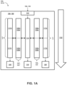
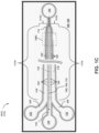
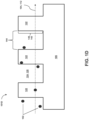
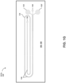
- FIGs. 1-A , 1-B , 1-C , 1-D , 1-E , 1-F , 1-G , and 1-H depict various views of an exemplary CIF device 100 or portions thereof.
- FIG. 1-A is a block diagram 101A illustrating various aspects of an exemplary CIF device 100.
- CIF device 100 is configured for modulating a concentration of particles 102 of a desired size in a microfluidic flow 104. It is to be understood that microfluidic flow 104 includes fluids for testing, e.g., to determine whether significant amounts of particles 102 of the desired size are present.
- CIF device 100 includes a substrate 106.
- Substrate 106 includes at least one CIF module 108.
- Substrate 106 defines in each CIF module 108 a central channel 110.
- Central channel 110 extends along a flow path 112 between a central channel flow input 114 and a central channel flow output 116.
- Substrate 106 defines a plurality of micro-features 122 adjacent to central channel 110.
- Plurality of micro-features 122 defines a plurality of gaps 124.
- Plurality of micro-features 122 separates central channel 110 from at least one side channel network 117.
- Plurality of gaps 124 are configured to fluidically couple central channel 110 to side channel network 117.
- Side channel network 117 extends along central channel 110 to at least one side channel output 120.
- Side channel network 117 includes one or more of a first side channel network portion 117a and a second side channel network portion 117b.
- side channel network 117 is characterized by a decreasing flow resistance along at least a portion of flow path 112 effective to modulate concentration of particles 102 of the desired size in microfluidic flow 104.
- the plurality of gaps 124a in first side channel network portion 117a are characterized by one or more of: a consistent flow fraction f gap and a plurality of different gap volumetric flow rates.
- the plurality of gaps 124 in side channel network 117 are characterized by one or more of a consistent flow fraction f gap and a plurality of different gap volumetric flow rates.
- FIG. 1-B is a top view schematic 101B illustrating various aspects of first side channel network portion 117a, including features illustrated in block form in FIG. 1-A , such as microfluidic flow 104, substrate 106, CIF module 108, central channel 110, flow path 112, plurality of micro-features 122a, and plurality of gaps 124a.
- first side channel network portion 117a includes a plurality of side channel curves 119 adjacent to central channel 110.
- First side channel network portion 117a includes at least a portion of plurality of micro-features 122a, and at least a portion of plurality of gaps 124a.
- Plurality of side channel curves 119 are characterized by a corresponding plurality of lengths 121a that decrease along flow path 112.
- Each side channel curve 119 fluidically couples at least one gap of plurality of gaps 124a in first side channel network portion 117a to one or more of an adjacent gap in plurality of gaps 124a and an adjacent curve in plurality of curves 119.
- FIG. 1-C is a top view schematic 101C illustrating various aspects of second side channel network portion 117b, including features illustrated in block form in FIG. 1-A , such as particles 102, microfluidic flow 104, substrate 106, CIF module 108, central channel 110, flow path 112, central channel flow input 114, central channel flow output 116, plurality of micro-features 122a, plurality of gaps 124a, and side channel output 120.
- second side channel network portion 117b includes a side channel 118 adjacent to central channel 110.
- Second side channel network portion 117b includes at least a portion of plurality of micro-features 122b.
- Second side channel network portion 117b includes at least a portion of plurality of gaps 124b.
- Side channel 118 is characterized by a flow cross-section 139 (see FIG. 1-H ).
- Flow cross-section 139 increases along flow path 112 such that plurality of gaps 124b in second side channel network portion 117b are characterized by one or more of a consistent flow fraction f gap and a plurality of different gap volumetric flow rates.
- side channel network 117 may include first side channel network portion 117a followed by second side channel network portion 117b in sequence along flow path 112.
- CIF device 100 may include two of side channel networks 117, 117'.
- Side channel networks 117, 117' may be adjacent to central channel 110.
- two side channel networks 117, 117' may be separated by central channel 110 and may be located on either side of central channel 110.
- substrate 106 may define two first side channel networks 117a, 117a' including at least two pluralities of side channel curves 119, 119' adjacent to central channel 110 and at least two pluralities of micro-features 122a, 122a'.
- At least two pluralities of side channel curves 119, 119' may be characterized by at least two corresponding pluralities of lengths 121a, 121a' that decrease along flow path 112.
- Central channel 110 may be separated from each of at least two pluralities of side channel curves 119, 119' by each plurality of micro-features 122a, 122a'.
- At least two pluralities of micro-features 122a, 122a' may define at least two pluralities of gaps 124a, 124a'. At least two pluralities of gaps 124a, 124a' may be configured to fluidically couple central channel 110 and pluralities of side channel curves 119, 119' through pluralities of micro-features 122a, 122a'. Each of pluralities of side channel curves 119, 119' may fluidically couple at least one corresponding gap of pluralities of gaps 124a, 124a' in first side channel network portion 117a to one or more of: an adjacent corresponding gap in pluralities of gaps 124a, 124a' and an adjacent corresponding curve in pluralities of side channel curves 119, 119'.
- substrate 106 may define two second side channel network portions 117b, 117b' including at least two side channels 118, 118' adjacent to central channel 110 and at least two pluralities of micro-features 122b, 122b'.
- Central channel 110 may be separated from each of side channels 118, 118' by each plurality of micro-features 122b, 122b'.
- Pluralities of micro-features 122b, 122b' may define at least two pluralities of gaps 124b, 124b'.
- Pluralities of gaps 124b, 124a' may be configured to fluidically couple central channel 110 and side channels 118, 118' through pluralities of micro-features 122b, 122b'.
- substrate 106 may define at least two side channels 118, 118', any description herein referring to at least one side channel 118 or features associated with at least one side channel 118, such as micro-features 122', may correspondingly extend to at least one side channel 118' or corresponding features thereof, such as micro-features 122'. Further, for example, wherein substrate 106 may define at least two side channels 118, 118', each side channel 118, 118' and corresponding associated features thereof may be the same or different.
- side channel 118 and associated features thereof may be a mirror image with respect to side channel 118' and corresponding associated features thereof across central channel 110 along at least a portion of flow path 112.
- depths 142 and 142' may be the same or different, e.g., the same.
- plurality of micro-features 122 and plurality of gaps 124 may have the same or different dimensions, e.g., the same, compared to plurality of micro-features 122' and plurality of gaps 124' along at least a portion of flow path 112.
- plurality of micro-features 122 and plurality of gaps 124 may be aligned or offset, e.g., aligned, along at least a portion of flow path 112 with respect to plurality of micro-features 122' and plurality of gaps 124'.
- corresponding features of central channel 110 may be the same or different, e.g., the same, as corresponding features of side channels 118 and/or 118'.
- depths 140, 142, and 142' may be the same or different, e.g., the same. It is explicitly contemplated all corresponding associated features indicated herein by similar feature numbers and distinguished by the prime symbol may be the same or different in such manner.
- FIG. 1-D is a cross-section view 101D along flow path 112, illustrating various aspects of exemplary CIF device 100.
- FIG. 1-E is a close-up top view 101E along flow path 112, illustrating various aspects of exemplary CIF device 100 in detail.
- Plurality of gaps 124 in each CIF module 108 may be characterized by an average gap cross-sectional area 126 parallel to flow path 112.
- Average gap cross-sectional area 126 may be sized compared to particles 102 of desired size effective to mitigate or eliminate fouling of plurality of gaps 124 by particles 102. For example, gaps of size comparable to the desired size may be fouled or obstructed by particles 102. Selecting average gap cross-sectional area 126 to be large compared to particles 102 may mitigate or eliminate such fouling.
- Average gap cross-sectional area 126 may be sized compared to particles 102 of desired size effective to mitigate or eliminate steric exclusion of particles 102 by plurality of gaps 124.
- conventional size exclusion filters function by physically or sterically excluding particles on the basis of size using gaps that are smaller than the particles to be excluded. Selecting average gap cross-sectional area 126 to be large compared to particles 102 may mitigate or eliminate such steric size exclusion, such that gaps 124 may exclude particles 102 based on microfluidic flow behavior in CIF device 100, even though average gap cross-sectional area 126 is large compared to particles 102.
- Each gap in plurality of gaps 124 in one or more of first side channel network 117a and second side channel network 117b may be characterized by substantially a same cross-sectional flow area 126 in a plane parallel to flow path 112.
- Plurality of gaps 124, for example, in one or more of first side channel network 117a and second side channel network 117b may be substantially equally spaced along flow path 112.
- Plurality of gaps 124 in each CIF module 108 may include a number of gaps 124 of at least about one or more of: 50, 75, 100, 150, 200, 250, 500, 750, 1,000, 2,500, 5,000, 7,500, 10,000, 50,000, 100,000, 500,000, and 1,000,000, or a range between any two of the preceding values.
- plurality of gaps 124 in one or more of first side channel network 117a and second side channel network 117b may be characterized by an average aspect ratio of a width 144 of each gap 124 parallel to flow path 112 to a depth 142 of each gap 124 in substrate 106.
- the aspect ratio of width 144 to depth 142 may be of less than about one or more of about: 16:1, 15:1, 10:1, 5:1, 4:1, 3:1, 2:1, 1:1, 1:2, 1:3, 1:4, 1:5, 1:10, 1:15, 1:20, 1:25, and 1:30.
- Plurality of gaps 124 may be characterized by an average gap depth 142 in substrate 106.
- Channel 110 may be characterized by a depth 140 in substrate 106.
- Average gap depth 142 may be a percentage of depth 140 of about one or more of: 5, 6, 7, 8, 9, 10, 15, 20, 25, 30, 40, 50, 60, 70, 80, 90, and 100.
- Depth 140 may be a value in ⁇ m of greater than one or more of about: 5, 10, 15, 20, 25, 30, 35, 40, 45, 50, 75, 100, 125, 150, 200, 250, 300, 400, and 500.
- central channel 110 and plurality of gaps 124 may, in one or more of first side channel network 117a and second side channel network 117b being respectively characterized by a central channel width 136 perpendicular to both flow path 112 and depth 140 of central channel 110.
- Central channel 110 and plurality of gaps 124 may be characterized by an average gap width 144 parallel to flow path 112. Average gap width 144 may be greater than a percentage of width 136 of one or more of about: 10, 20, 21, 22, 23, 24, 25, 30, 35, 40, 45, and 50.
- FIG. 1-F is a close-up perspective view 101F along flow path 112, illustrating various aspects of exemplary CIF device 100.
- central channel 110 in each CIF module 108 may be fluidically coupled to an input source 128 through central channel flow input 114.
- side channel network 117 may be fluidically coupled to input source 128 through plurality of gaps 124 to central channel 110.
- Central channel 110 may be fluidically coupled to a retentate output reservoir 130.
- Side channel network 117 may be fluidically coupled to a filtrate output reservoir 132.
- flow path 112 may include one or more turns 134 in substrate 106.
- Each CIF module 108 may be configured to provide a flow path length in cm of at least one or more of about: 0.1, 0.5, 0.75, 1, 2, 2.5, 5, 7.5, 10, 15, 20, 25, 50, 75, 100, 250, 500, and 1000, or a range between any two of the preceding values.
- FIG. 1-H is a cross section view 101H perpendicular to flow path 112, illustrating various aspects of second side channel network portion 117b in exemplary CIF device 100.
- second side channel network portion 117b may be characterized by a ratio of a cross-sectional area 139 of side channel 118 to a cross-sectional area 137 of central channel 110.
- Cross-sectional areas 137, 139 may be perpendicular to flow path 112. The ratio of cross-sectional areas 137, 139 may increase along at least a portion of flow path 112.
- the ratio of cross-sectional areas 137, 139 may increase along at least a portion of flow path 112 according to a width 138 of at least one side channel 118 and a width 136 of central channel 110. Each width 136, 138 may be perpendicular to both flow path 112 and a depth 140 of central channel 110 in substrate 106.
- Flow cross-sectional area 137 may be constant along flow path 112, e.g., along second side channel network portion 117b. Further, for example, flow cross-sectional area 139 of side channel 118 may increase along flow path 112.
- Each CIF module 108 may be characterized along second side channel network portion 117b by a flow cross-sectional area 137 of central channel 110 perpendicular to flow path 112.
- Flow cross-sectional area 137 may be, for example, constant, increasing, or decreasing along flow path 112.
- cross-sectional area 139 of side channel 118 may be constant, increasing, or decreasing along flow path 112.
- the symbol R c may represent flow resistance of central channel 110.
- the symbol R s ( i- 1) may represent flow resistance in a portion of at least one side network 117 between a gap i -1 and a gap i in plurality of gaps 124.
- the increment symbol i may be increased by 1 for each gap in plurality of gaps 124 along flow path 112.
- the symbol R s ( i ) may represent flow resistance in a portion of at least one side network 117 between the gap i and a gap i + 1 in plurality of gaps 124.
- the symbol R ( w , d , ⁇ , L ) may represent resistance of a channel segment in a portion of central channel 110 or at least one side network 117.
- the symbol w may represent a width corresponding to approximating the channel segment as a rectangular channel.
- the symbol d may represent a depth corresponding to approximating the channel segment as a rectangular channel.
- the symbol L may represent a length corresponding to approximating the channel segment as a rectangular channel.
- the symbol ⁇ may represent a viscosity of the fluid.
- Each L may correspond to one of plurality of lengths 121a corresponding to plurality of side channel curves 119.
- Each L may correspond to a length of the channel segment along side channel 118 between a corresponding pair of gaps in plurality of gaps 124.
- CIF device 100 may be characterized as follows. At least a portion of plurality of gaps 124 may be characterized by a flow fraction f gap compared to a volumetric flow Q c ( i ) through central channel 110 at the gap i .
- the flow fraction f gap may be less than one or more of about: 0.01, 0.0075, 0.005, 0.0025, 0.001, 0.00075, 0.0005, 0.00025, 0.0001, 0.000075, 0.00005, 0.000025, and 0.00001.
- flow fraction f gap may be an average characterized by a percent standard deviation among plurality of gaps 124 of less than about ⁇ 1, 2.5, 5, 7.5, 10, 15, and 20.
- Each CIF module 108 may be configured, upon conducting the microfluidic flow using a mixture of 1% w/w 4 ⁇ m polystyrene microbeads in water at a temperature of 25 °C and a flow pressure of 2 PSI, to concentrate particles 102 of the desired size in microfluidic flow 104.
- the concentration, from a starting particle concentration at central channel flow input 114 to a final concentration at central channel flow output 116 may include a concentration factor of one or more of about: 1.5:1, 2:1, 2.5:1, 3:1, 3.5:1, 4:1, 5:1, 7,5:1, 10:1, 15:1, 20:1, 25:1, 50:1, 75:1, 100:1, 125:1, 150:1, 200:1, and 250:1.
- Each CIF module 108 may be configured to retain a percentage of particles 102 in microfluidic flow 104. The percentage of particles 102 retained may be at least one or more of about: 50, 55, 60, 65, 70, 75, 80, 85, 90, 95, 97.5, 99, and 100.
- the desired size of particles 102 may be characterized by an effective average diameter in ⁇ m of greater than one or more of about: 0.5, 1, 1.2, 1.4, 1.6, 1.8, 2, 2.5, 3, 3.5, 4, 4.5, 5, 7.5, 10, 15, 20, 25, 50, 75, 100, 125, and 150.
- Plurality of gaps 124 may be configured in each CIF module 108 with an average gap cross-sectional area 126 parallel to flow path 112.
- Average gap cross-sectional area 126 may be greater than the desired size of particles 102 to be separated from the microfluidic flow.
- Average gap cross-sectional area 126 may be greater than the desired size of particles 102 by a factor of one or more of about: 2:1, 3:1,4:1,5:1,7.5:1,10:1,15:1, and 20:1.
- particles 102 may include one or more of red blood cells, platelets, white blood cells, circulating tumor cells, stem cells, effete stored erythrocytes, T-cells derived from autologous T-cell expansion, organic microparticles, inorganic microparticles, organometallic microparticles, metallic microparticles, aerosol particles, bacteria, yeast, fungi, algae, viruses, micro-invertebrates or eggs thereof, pollen, cell or tissue fragments, cell clusters, cellular debris (e.g., cellular debris associated with DNA or RNA purification), bioreactor-produced cells or particulates, proteins, protein aggregates, prions, vesicles, liposomes, precipitates (e.g., precipitates from blood or a blood fraction, industrial process precipitates, wastewater precipitates, and the like), particulates or cells from fermented foods (e.g., particulates or cells from fermented beverages), macromolecules, macromolecular aggregates, DNA, organelles, spor
- Microfluidic flow 104 may include particles 102 in a fluid.
- the fluid may include one or more of: whole blood or a fraction thereof; amniotic fluid; umbilical cord blood; bile; cerebrospinal fluid; skin cells; exudate; feces; gastric fluid; lymph; milk; mucus; peritoneal fluid; plasma; pleural fluid; pus; saliva; sebum; semen; sweat; synovial fluid; tears; urine; water; buffer; groundwater; seawater; rainwater; sap; animal tissue homogenate, extract, or pressing; plant tissue homogenate, extract, or pressing; wastewater; an industrial process fluid or fluid product; fermentation broth; crystallization or precipitation fluid; a food or food process intermediate (e.g., a fermented beverage); oil; inorganic solvent; organic solvent; ionic solvent; honey; syrup; lymphatic fluid; serum; and lysate.
- a food or food process intermediate e.g., a fermented beverage
- oil inorganic
- CIF module 108 may be configured capable of conducting the microfluidic flow as one or more of: a gravitationally-directed flow, a vacuum directed flow, an electroosmotic directed flow, an electrokinetic directed flow, a mechanically pumped flow, e.g., using a syringe pump; and the like.
- Each CIF module 108 may be configured such that a volumetric flow of central channel flow output 116 and a volumetric flow of at least one side channel output 120 are substantially equal.
- substrate 106 may include two or more of CIF modules 108, 108'.
- Substrate 106 may include an array of two or more CIF modules 108, 108' fluidically coupled in series or in parallel.
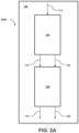
- substrate 106 may include an array 200A of the two or more CIF modules 108, 108' fluidically coupled in series, as depicted in FIG. 2A .
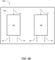
- Substrate 106 may include an array 200B of two or more CIF modules 108, 108' fluidically coupled in parallel, as depicted in FIG. 2-B .
- the arrangements and flows depicted in FIGs. 2-A and 2-B are merely exemplary, and other arrangements and flows are contemplated.
- CIF device 100 may further include at least one additional separation device 302 as depicted in FIG. 3 .
- Separation devices 302, 302', 302" may be fluidically coupled to one or more of: central channel flow input 114, central channel flow output 116, and at least one side channel flow output 120.
- Additional separation devices 302, 302', 302" may include one or more of: a filter, a centrifuge, an electrophoresis device, a chromatography column, a fluid evaporator, a sedimentation device, a deterministic lateral displacement device, a plasma skimmer, a margination device, a magnetic separator, an ultrasound focusing device, a density gradient separator, and the like.
- Substrate 106 may include one or more of: a glass, a polymer, a metal, a ceramic, and a semiconductor.
- Substrate 106 may include a thermoplastic polymer, e.g., polycarbonate, or an elastomeric rubber, e.g., polydimethylsiloxane.
- CIF device 100 may be configured to be one or more of: disposable, sterile, and sterilizable.
- FIG. 4 is a flow diagram illustrating a method 400 for controlled incremental filtration.
- Method 400 may concentrate particles of a desired size in a fluid.
- Method 400 may include 402 providing the fluid including the particles of the desired size. It is to be understood that "the fluid including the particles of the desired size" may include fluids for testing, e.g., to determine whether significant amounts of the particles of the desired size are present.
- Method 400 may include 404 flowing the fluid comprising the particles of the desired size along a flow path through a central channel.
- the central channel may include a plurality of gaps that fluidically couple the central channel to at least one adjacent side channel network.
- Method 400 may include 406 decreasing flow resistance along at least a portion of the flow path effective to modulate the concentration of particles by contacting the fluid comprising the particles of the desired size to the plurality of gaps.
- Method 400 may include 408, 408A selecting the plurality of gaps including an average flow cross-section larger than the particles of the desired size.
- Method 400 may include 408, 408B causing different gap volumetric flow rates among at least a portion of the plurality of gaps.
- Method 400 may include 408, 408C causing a consistent flow fraction f gap in the central channel to traverse each gap in the plurality of gaps and flow through the at least one side channel network along the flow path.
- Method 400 may include providing the at least one side channel network.
- the at least one side channel network may include a first channel network portion.
- the first channel network portion may include a plurality of side channel curves adjacent to the central channel.
- the plurality of side channel curves may be characterized by decreasing length along the flow path effective to decrease the flow resistance.
- the at least one side channel network may include a second side channel network portion.
- the second side channel network portion may include a side channel adjacent to the central channel.
- the side channel may be characterized by an increasing flow cross-section along the flow path effective to cause one or more of the consistent flow fraction f gap and the plurality of different gap volumetric flow rates.
- the method may include flowing the fluid through the first side channel network portion followed by the second side channel network portion in sequence along the flow path.
- Method 400 may include selecting the plurality of gaps including an average gap cross-sectional area larger compared to the particles of desired size. Compared to gaps smaller than the particles, the larger average gap cross-sectional area larger may be effective for mitigating or eliminating fouling of the plurality of gaps by the particles. The larger average gap cross-sectional area larger may also be effective for mitigating or eliminating steric exclusion of the particles by the plurality of gaps.
- Method 400 may include providing an average aspect ratio of a width of each gap along the flow path to a depth of each gap of less than one or more of: 16:1, 15:1, 10:1, 5:1, 4:1, 3:1, 2:1, 1:1, 1:2, 1:3, 1:4, 1:5, 1:10, 1:15, 1:20, 1:25, and 1:30.
- the central channel may include a depth in ⁇ m of greater than one or more of about: 5, 10, 15, 20, 25, 30, 35, 40, 45, 50, 75, 100, 125, 150, 200, 250, 300, 400, and 500.
- An average depth of the plurality of gaps may be greater than a depth of the central channel by a percentage of one or more of about: 5, 6, 7, 8, 9, 10, 15, 20, 25, 30, 40, 50, 60, 70, 80, 90, and 100.
- An average gap width along the flow path of the plurality of gaps may be greater than a width of the central channel by a percentage of one or more of about: 20, 21, 22, 23, 24, 25, 30, 40, 50, 60, 70, 80, 90, and 100.
- the average gap flow cross-section may be larger than the particles of the desired size by a factor of one or more of about: 2:1, 3:1, 4:1, 5:1, 7.5:1, 10:1, 15:1, and 20:1.
- Method 400 may include providing two side channel networks adjacent to the central channel along the flow path.
- the method may include providing a flow path length in cm of at least one or more of about: 0.1, 0.5, 0.75, 1, 2, 2.5, 5, 7.5, 10, 15, 20, 25, 50, 75, 100, 250, 500, and 1000.
- the method may include providing the plurality of gaps for each at least one side channel network including a number of gaps of at least about one or more of: 50, 75, 100, 150, 200, 250, 500, 750, 1,000, 2,500, 5,000, 7,500, 10,000, 50,000, 100,000, 500,000, and 1,000,000.
- the method may include increasing a ratio along the flow path of a cross-sectional area of the at least one side channel to a cross-sectional area of the central channel.
- the ratio of the cross-sectional area of the at least one side channel to the cross- sectional area of the central channel may be increased along the flow path according to a width of the at least one side channel and a width of the central channel.
- the method may include increasing the ratio along the flow path, including holding the cross-sectional area of the central channel constant along the flow path and increasing the cross-sectional area of the at least one side channel along the flow path.
- the method may include increasing the ratio along the flow path comprising decreasing the cross-sectional area of the central channel constant along the flow path and maintaining or increasing the cross-sectional area of the at least one side channel along the flow path.
- the method may include increasing the ratio along the flow path including maintaining, increasing, or decreasing the cross-sectional area of the central channel along the flow path.
- the method may include increasing the ratio along the flow path including maintaining, increasing, or decreasing the cross-sectional area of the at least one side channel along the flow path.
- the method may include increasing a ratio along the flow path of a fluidic resistance of the at least one side channel to a fluidic resistance of the central channel.
- the symbol R c may represent flow resistance of central channel 110.
- the symbol R s ( i -1) may represent flow resistance in a portion of at least one side network 117 between a gap i- 1 and a gap i in the plurality of gaps.
- the increment symbol i may be increased by 1 for each gap in the plurality of gaps along the flow path.
- the symbol R s ( i ) may represent flow resistance in a portion of at least one side network between the gap i and a gap i + 1 in the plurality of gaps.
- the symbol R ( w, d, ⁇ , L ) may represent resistance of a channel segment in a portion of the central channel or at least one side network.
- the symbol w may represent a width corresponding to approximating the channel segment as a rectangular channel.
- the symbol d may represent a depth corresponding to approximating the channel segment as a rectangular channel.
- the symbol L may represent a length corresponding to approximating the channel segment as a rectangular channel.
- the symbol ⁇ may represent a viscosity of the fluid.
- the flow fraction f gap at a gap i may be a volumetric flow Q c (i) through the central channel at the gap i of less than one or more of about: 0.01, 0.0075, 0.005, 0.0025, 0.001, 0.00075, 0.0005, 0.00025, 0.0001, 0.000075, 0.00005, 0.000025, and 0.00001.
- the method may include causing the flow fraction f gap to have a percent standard deviation among the plurality of gaps of less than about one or more of: ⁇ 1, 2.5, 5, 7.5, 10, 15, and 20.
- the method may include providing each gap in the plurality of gaps with substantially the same flow cross-section.
- the method may include providing the plurality of gaps substantially equally spaced along the flow path.
- Method 400 may include conducting at least one additional separation.
- the at least one additional separation may be conducted before or after flowing the fluid including the particles of the desired size through the central channel.
- the additional separation may include one or more of filtering, centrifuging, electrophoresis, chromatography, fluid evaporation, sedimentation, deterministic lateral displacement, plasma skimming, margination, magnetic separation, ultrasound focusing device, density gradient separation, and the like.
- Method 400 may include concentrating the particles of the desired size in the fluid in the central channel by a concentration factor of one or more of about: 1.5:1, 2:1, 2.5:1, 3:1, 3.5:1, 4:1, 5:1, 7,5:1, 10:1, 15:1, 20:1, 25:1, 50:1, 75:1, 100:1, 125:1, 150:1, 200:1, and 250:1.
- the method may include retaining a percentage of the particles of the desired size in the fluid in the central channel of at least one or more of about: 50, 55, 60, 65, 70, 75, 80, 85, 90, 95, 97.5, 99, and 100.
- the desired size of the particles may be characterized by an effective average diameter in ⁇ m of greater than one or more of about: 0.5, 1, 1.2, 1.4, 1.6, 1.8, 2, 2.5, 3, 3.5, 4, 4.5, 5, 7.5, 10, 15, 20, 25, 50, 75, 100, 125, and 150.
- the particles may include one or more of: red blood cells, platelets, white blood cells, circulating tumor cells, stem cells, effete stored erythrocytes, T-cells derived from autologous T-cell expansion, organic microparticles, inorganic microparticles, organometallic microparticles, metallic microparticles, aerosol particles, bacteria, yeast, fungi, algae, viruses, micro-invertebrates or eggs thereof, pollen, cell or tissue fragments, cell clusters, cellular debris (e.g., cellular debris associated with DNA or RNA purification), bioreactor-produced cells or particulates, proteins, protein aggregates, prions, vesicles, liposomes, precipitates (e.g., precipitates from blood or a blood fraction, industrial process precipitates, wastewater precipitates, and the like), particulates or cells from fermented foods (e.g., particulates or cells from fermented beverages), macromolecules, macromolecular aggregates, DNA, organelles, spores, stem
- the fluid may include one or more of: whole blood or a fraction thereof; amniotic fluid; umbilical cord blood; bile; cerebrospinal fluid; skin cells; exudate; feces; gastric fluid; lymph; milk; mucus; peritoneal fluid; plasma; pleural fluid; pus; saliva; sebum; semen; sweat; synovial fluid; tears; urine; water; buffer; groundwater; seawater; rainwater; sap; animal tissue homogenate, extract, or pressing; plant tissue homogenate, extract, or pressing; wastewater; an industrial process fluid or fluid product; fermentation broth; crystallization or precipitation fluid; a food or food process intermediate (e.g., a fermented beverage); oil; inorganic solvent; organic solvent; ionic solvent; honey; syrup; lymphatic fluid; serum; lysate; and the like.
- a food or food process intermediate e.g., a fermented beverage
- oil inorganic solvent; organic solvent; ionic solvent; honey; syrup; lymphatic
- Method 400 may include collecting one or more of a retentate fraction from the central channel and a filtrate fraction from the at least one side network.
- the method may include collecting a fraction of the fluid comprising an increased or a decreased concentration of the particles of the desired size.
- the method may include flowing the fluid including conducting one or more of: gravitational flow, vacuum flow, electroosmotic flow, electrokinetic flow, mechanically pumped flow (e.g., using a syringe pump), and the like.
- the method may include providing substantially equal volumetric flows of the fluid at an output of the central channel flow and an output of the at least one side channel.
- the method may include operating two or more instances of the method in one or more of: parallel operation and serial operation.
- the method may include flowing the fluid including the particles of the desired size by flowing along one or more turns in the flow path.
- FIG. 5 is a flow diagram illustrating a method 500 for designing a CIF device.
- the CIF device may modulate a concentration of particles of a desired size in a fluid.
- Method 500 may include 502 preparing a design for a CIF device.
- the CIF device design may include a central channel.
- the central channel may extend along a flow path between a central channel flow input and a central channel flow output.
- the CIF device design may include at least one side channel adjacent to the central channel.
- the at least one side channel may extend along the flow path to at least one side channel output.
- the central channel may be separated from the at least one side channel by a plurality of micro-features.
- the plurality of micro-features may define a plurality of gaps i .
- the plurality of gaps may be configured to fluidically couple the central channel and the at least one side channel through the plurality of micro-features.
- Method 500 may include 504 selecting a desired flow fraction f gap for the CIF device.
- Method 500 may include 506 determining a plurality of adjusted dimensions along the flow path.
- Method 500 may include 508 adapting the CIF device design to incorporate the plurality of the adjusted dimensions. Incorporating the adjusted dimensions may be effective to provide a decreasing flow resistance along at least a portion of the flow path effective to modulate the concentration of particles of the desired size in the fluid for the design for the CIF device.
- the adjusted dimensions along the flow path may include, in a first side network portion, a decreasing length of each of a plurality of side channel curves.
- the plurality of side channel curves may be adjacent to the central channel in the first side channel network portion.
- the adjusted dimensions along the flow path may include, in a second side network portion, an increasing ratio of a cross-sectional area of at least one side channel to a cross-sectional area of the central channel.
- the at least one side channel may be adjacent to the central channel in the second side network portion.
- Method 500 may include providing one or more test CIF devices. Each of the test CIF devices may be characterized by a corresponding test flow fraction f gap .
- the method may include flowing the particles of the desired size in the fluid through the one or more test CIF devices.
- the method may include determining the desired flow fraction f gap for the design for the CIF device based on each corresponding test flow fraction f gap in the one or more test CIF devices.
- Method 500 may include determining the plurality of adjusted dimensions by determining a central channel flow resistance R c .
- the method may include determining a first side channel segment flow resistance corresponding to a first side channel segment between a first pair of adjacent gaps in the plurality of gaps along the flow path.
- the first flow resistance may be determined according to a first functional relationship between: a viscosity of the fluid; a first effective side channel width w and a first effective channel depth d corresponding to a first cross-sectional area at the first side channel segment; and a length L of the first side channel segment.
- the method may include determining a second side channel segment flow resistance corresponding to a second side channel segment between a second pair of adjacent gaps in the plurality of gaps along the flow path.
- the second side channel segment may be located immediately downstream of the first side channel segment.
- the second side channel segment flow resistance may be determined according to a second functional relationship between: the central channel flow resistance, the first side channel segment flow resistance, and the desired flow fraction f gap for the CIF device.
- the method may include recalculating the first functional relationship using one or more adjusted dimensions comprising one or more of: a second effective side channel width w; a second effective channel depth d ; and a second side channel length L .
- the one or more adjusted dimensions may be effective to cause the first side channel segment flow resistance according to the first functional relationship to equal the second side channel segment flow resistance.
- the one or more adjusted dimensions may be effective to cause the second side channel segment flow resistance according to the second functional relationship to be lower than the first side channel segment flow resistance by an amount determined according to the second functional relationship.
- the method may include conducting one or more of the preceding steps for a plurality of iterations to calculate the plurality of the adjusted dimensions.
- Method 500 may include holding the cross-sectional area of the central channel constant along the flow path and each effective channel depth d such that the ratio increases according to the one or more of: increasing the second effective side channel width w; and decreasing the second side channel length L .
- the side channel network may include a plurality of side channel curves characterized by a plurality of side channel curve lengths. The plurality of side channel curves may be adjacent to the central channel.
- the method may include progressively decreasing the plurality of side channel curve lengths along the flow path.
- the side channel network may include a side channel adjacent to the central channel.
- the method may include progressively increasing a width of the side channel along the flow path.
- the method may include, for each functional relationship, approximating each channel segment as a rectangular channel.
- the method may include recalculating the first functional relationship by numerically solving the first functional relationship for the one or more adjusted dimensions.
- the symbol R s (i-1) may represent the first side channel segment flow resistance.
- the symbol R s (i) may represent the second side channel segment flow resistance.
- Method 500 may include selecting the plurality of gaps in the design for the CIF device characterized by an average gap cross-sectional area parallel to the central channel along the flow path.
- the average gap cross-sectional area may be selected larger compared to the particles of desired size effective for mitigating or eliminating fouling of the plurality of gaps by the particles.
- the average gap cross-sectional area may be selected larger compared to the particles of desired size effective for mitigating or eliminating steric exclusion of the particles by the plurality of gaps.
- the design for the CIF device may include at least two side channel networks adjacent to the central channel and at least two corresponding pluralities of the micro-features.
- the central channel may be separated from each of the at least two side channels by each plurality of micro-features.
- the at least two pluralities of micro-features may define at least two pluralities of gaps.
- the at least two pluralities of gaps may be configured to fluidically couple the central channel and the at least two side channels through the at least two pluralities of the micro-features.
- the design for the CIF device may include one or more turns in the flow path.
- each gap in the plurality of gaps in the design for the CIF device may be characterized by substantially the same cross-sectional flow area in a plane parallel to the flow path.
- the plurality of gaps in the design for the CIF device may be substantially equally spaced along the flow path.
- the design for the CIF device may be configured to provide a flow path length in cm of at least one or more of about: 0.1, 0.5, 0.75, 1, 2, 2.5, 5, 7.5, 10, 15, 20, 25, 50, 75, 100, 250, 500, and 1000.
- the plurality of gaps for the design for the CIF device may include a number of gaps of at least about one or more of: 50, 75, 100, 150, 200, 250, 500, 750, 1,000, 2,500, 5,000, 7,500, 10,000, 50,000, 100,000, 500,000, and 1,000,000.
- the design for the CIF device may be characterized by a cross-sectional area of the central channel perpendicular to the flow path.
- the cross-sectional area of the central channel may be constant, increasing, or decreasing along the flow path.
- the design for the CIF device may be characterized by a cross-sectional area of the at least one side channel perpendicular to the flow path.
- the cross-sectional area of the at least one side channel may be constant, increasing, or decreasing along the flow path.
- the plurality of gaps in the design for the CIF device may be characterized by an average aspect ratio of a width of each gap parallel to the flow path to a depth of each gap of less than about one or more of about: 16:1, 15:1, 10:1, 5:1, 4:1, 3:1, 2:1, 1:1, 1:2, 1:3, 1:4, 1:5, 1:10, 1:15, 1:20, 1:25, and 1:30.
- the plurality of gaps in the design for the CIF device may be characterized by an average gap depth.
- the average gap depth may be greater than a percentage of a depth of the central channel of about one or more of: 5, 6, 7, 8, 9, 10, 15, 20, 25, 30, 40, 50, 60, 70, 80, 90, and 100.
- the central channel may be characterized by a depth in ⁇ m of greater than one or more of about: 5, 10, 15, 20, 25, 30, 35, 40, 45, 50, 75, 100, 125, 150, 200, 250, 300, 400, and 500.
- the central channel and the plurality of gaps may be respectively characterized by (1) a central channel width perpendicular to both the flow path and the depth of the central channel in the substrate and (2) an average gap width parallel to the flow path.
- the average gap width may be greater than a percentage of the width of the central channel of one or more of about: 10, 20, 21, 22, 23, 24, 25, 30, 35, 40, 45, and 50.
- the design for the CIF device may be configured such that compared to a volumetric flow Q c (i) through the central channel at a gap i, the desired flow fraction f gap is selected to be less than one or more of about: 0.01, 0.0075, 0.005, 0.0025, 0.001, 0.00075, 0.0005, 0.00025, 0.0001, 0.000075, 0.00005, 0.000025, and 0.00001.
- the design for the CIF device may be configured effective to provide a realized flow fraction f gap among the plurality of gaps characterized by a percentage standard deviation of less than about ⁇ 1, 2.5, 5, 7.5, 10, 15, and 20.
- the design for the CIF device may be configured effective to concentrate the particles of the desired size in the microfluidic fluid flow from a starting particle concentration at the central channel flow input to a final concentration at the central channel flow output by a concentration factor of one or more of about: 1.5:1, 2:1, 2.5:1, 3:1, 3.5:1, 4:1, 5:1, 7,5:1, 10:1, 15:1, 20:1, 25:1, 50:1, 75:1, 100:1, 125:1, 150:1, 200:1, and 250:1.
- the design for the CIF device may be configured effective to retain a percentage of the particles in the microfluidic fluid flow, the percentage of particles retained being at least one or more of about: 50, 55, 60, 65, 70, 75, 80, 85, 90, 95, 97.5, 99, and 100.
- the plurality of gaps may be configured with an average gap cross-sectional area parallel to the flow path.
- the average gap cross-sectional area may be greater than the desired size of the particles.
- the desired size of the particles may be selected with an effective average diameter in ⁇ m of greater than one or more of about: 0.5, 1, 1.2, 1.4, 1.6, 1.8, 2, 2.5, 3, 3.5, 4, 4.5, 5, 7.5, 10, 15, 20, 25, 50, 75, 100, 125, and 150.
- the average gap cross-sectional area may be greater than the desired size of the particles by a factor of one or more of about: 2:1, 3:1, 4:1, 5:1, 7.5:1, 10:1, 15:1, and 20:1.
- the particles may include one or more of: red blood cells, platelets, white blood cells, circulating tumor cells, stem cells, effete stored erythrocytes, T-cells derived from autologous T-cell expansion, organic microparticles, inorganic microparticles, organometallic microparticles, metallic microparticles, aerosol particles, bacteria, yeast, fungi, algae, viruses, micro-invertebrates or eggs thereof, pollen, cell or tissue fragments, cell clusters, cellular debris (e.g., cellular debris associated with DNA or RNA purification), bioreactor-produced cells or particulates, proteins, protein aggregates, prions, vesicles, liposomes, precipitates (e.g., precipitates from blood or a blood fraction, industrial process precipitates, wastewater precipitates, and the like), particulates or cells from fermented foods (e.g., particulates or cells from fermented beverages), macromolecules, macromolecular aggregates, DNA, organelles, spores, stem
- the fluid may include one or more of: whole blood or a fraction thereof; amniotic fluid; umbilical cord blood; bile; cerebrospinal fluid; skin cells; exudate; feces; gastric fluid; lymph; milk; mucus; peritoneal fluid; plasma; pleural fluid; pus; saliva; sebum; semen; sweat; synovial fluid; tears; urine; water; buffer; groundwater; seawater; rainwater; sap; animal tissue homogenate, extract, or pressing; plant tissue homogenate, extract, or pressing; wastewater; an industrial process fluid or fluid product; fermentation broth; crystallization or precipitation fluid; a food or food process intermediate (e.g., a fermented beverage); oil; inorganic solvent; organic solvent; ionic solvent; honey; syrup; lymphatic fluid; serum; lysate; and the like.
- a food or food process intermediate e.g., a fermented beverage
- oil inorganic solvent; organic solvent; ionic solvent; honey; syrup; lymphatic
- the design for the CIF device may be configured effective to passively conduct microfluidic fluid flow as one or more of: gravitational flow, vacuum flow, electroosmotic flow, electrokinetic flow, mechanically pumped flow (e.g., using a syringe pump), and the like.
- the design for the CIF device may be configured such that a volumetric flow of the central channel flow output and a volumetric flow of the at least one side channel output are substantially equal.
- FIG. 6 is a block diagram illustrating a kit 600.
- Kit 600 includes any aspect of the CIF devices according to the first aspect, e.g., CIF device 100.
- kit 600 includes CIF device 100 configured for modulating a concentration of particles 102 of a desired size in a microfluidic flow 104.
- CIF device 100 includes substrate 106.
- Substrate 106 includes at least one CIF module 108.
- Substrate 106 defines in each CIF module 108 a central channel 110.
- Central channel 110 extends along a flow path 112 between a central channel flow input 114 and a central channel flow output 116.
- Substrate 106 defines a plurality of micro-features 122 adjacent to central channel 110.
- Plurality of micro-features 122 defines a plurality of gaps 124.
- Plurality of micro-features 122 separate central channel 110 from at least one side channel network 117.
- Plurality of gaps 124 are configured to fluidically couple central channel 110 to at least one side channel network 117.
- Side channel network 117 extends along central channel 110 to at least one side channel output 120.
- Side channel network 117 includes one or more of a first side channel network portion 117a and a second side channel network portion 117a.
- first side channel network portion 117a includes: a plurality of side channel curves 119 adjacent to central channel 110, at least a portion of plurality of micro-features 122a, and at least a portion of plurality of gaps 124a.
- Plurality of side channel curves 119 are characterized by a corresponding plurality of lengths 121a that decrease along flow path 112.
- Each side channel curve 119 fluidically couples at least one gap of plurality of gaps 124a in first side channel network portion 117a to one or more of: an adjacent gap in the plurality of gaps 124a and an adjacent curve in the plurality of curves 119.
- second side channel network portion 117b includes: a side channel 118 adjacent to the central channel 110, at least a portion of plurality of micro-features 122b, and at least a portion of plurality of gaps 124b.
- Side channel 118 is characterized by a flow cross-section 139.
- Flow cross-section 139 increases along flow path 112 such that plurality of gaps 124b in second side channel network portion 117b are characterized by one or more of: a consistent flow fraction f gap and a plurality of different gap volumetric flow rates.
- At least one side channel network 117 is characterized by a decreasing flow resistance along at least a portion of flow path 112 effective to modulate the concentration of particles 102 of the desired size in microfluidic flow 104.
- Kit 600 includes a set of instructions 602.
- Instructions 602 include directions to a user to carry any aspect of operating a CIF device as described herein, for example, any aspect of method 400.
- set of instructions 602 includes directions to a user to provide the fluid including particles 102 of the desired size.
- Instructions 602 include directions to a user to flow the fluid including the particles of the desired size along a flow path through the central channel.
- Set of instructions 602 may include directions to a user to decrease flow resistance along at least a portion of the flow path effective to modulate the concentration of particles by contacting the fluid comprising the particles of the desired size to the plurality of gaps.
- Set of instructions 602 may include directions to a user to select the plurality of gaps including an average flow cross-section larger with respect to the particles of the desired size.
- Set of instructions 602 may include directions to a user to cause different gap volumetric flow rates among at least a portion of the plurality of gaps.
- Set of instructions 602 may include directions to a user to cause a consistent flow fraction f gap in the central channel to traverse each gap in the plurality of gaps and flow through the at least one side channel network along the flow path
- the CIF devices described herein may promote efficiency and predictability of particle concentration in the central channel by permitting an equal amount of fluid to be taken by each side channel network from the central channel, for example, in embodiments including at least two side channels.
- the methods of CIF device design described herein may be used to create a CIF device mold using soft lithography, microCNC machining, laser ablation, or other well-known mold making techniques. Such techniques may simplify the design process and may allow creation of a device by changing a few, e.g., one or two parameters.
- the methods of CIF device design described herein may promote rapid prototyping.
- the methods of CIF device design described herein may facilitate production of longer CIF device flow paths capable of greater particle enrichment compared to shorter flow paths.
- the methods of CIF device design described herein may be simpler than complex CFD modeling techniques that may be computationally limited to a few dozen filtration points or gaps.
- the methods of CIF device design described herein may be less computationally demanding and may be used to quickly generate designs including many thousands of filtration points.
- the methods of CIF device design described herein may reduce the number of design parameters compared to such complex CFD modeling techniques, facilitating a fast, recursive, numerical approach to generate a CAD drawing for a desired CIF device.
- the methods of CIF device design described herein may also be more effective than such complex CFD modeling techniques, particularly with respect to predicting effectiveness of contemplated CIF designs.
- the methods of CIF device design described herein may permit devices of desirable volumetric throughput that may be driven by moderate pressure, passive methods, e.g., by gravitational pressure.
- the CIF devices described herein may concentrate particles above a desired size in a central flow channel compared to adjacent side channels.
- the central channel and side channels may be separated by gaps, which may be several times larger than the particles of interest, in contrast to known crossflow filtration, which may rely primarily on simple size exclusion.
- the CIF devices described herein may include side channels having a width that gradually increases along the flow path of the device to provide a filtration size cutoff corresponding to the particles of desired size. This architecture may facilitate calculation of dimensions suitable to provide a consistent filter fraction f gap at each gap.
- the methods of CIF device design described herein may, by numerically determining the side channel width, permit larger gaps as the filtration points compared to known design techniques. Accordingly, the methods of CIF device design described herein may permit construction of CIF devices with deeper channels compared to known design techniques, which may mitigate or avoid feature collapse or adhesion upon de-molding.
- analytical solutions may be used to generate a CAD drawing in a two-step process of identification followed by implementation. Predictions of flow dynamics often fail, for example in known CFD techniques, so a test step according to the methods described herein may facilitate choosing a suitable f gap value for manufacturing a complete design with the desired total degree of filtration/enrichment.
- the quick generation of CAD designs with many filtration points enables one to filter to a higher degree in a single device and/or enrich smaller particles.
- the methods and devices described herein permit the use of gaps much larger than the particle(s) of interest, without losing a significant amount of the particles to the side channels of the device.
- the methods of CIF device design described herein may provide an effective CIF device in a manageable footprint capable of more than just 'lab on a chip' applications, for example, even while the size of the relevant particle of interest may be much smaller, such as with platelets.
- the methods of CIF device design described herein may provide CIF devices that are more adjustable compared to macroscopic crossflow filtration.
- the methods of CIF device design described herein may permit the CIF devices to be made out of inexpensive materials such as injection molded plastics without highly-specialized filtration membranes.
- the central flow channel may have a constant width (w c ) and may be flanked by side channels having a width immediately downstream of gap i, w s (i) corresponding to a desired value of f gap , and the side channel width immediately downstream of the preceding gap, w s (i - 1).
- This recursive approach to calculating the side channel width may permit a CAD drawing of a device design to be built up quickly, using a small number of governing equations and simplifying assumptions.
- an assumption permitting an easily-implementable model is to treat the space between gaps as nodes that may allow equalization of pressure across the width of the device.
- relatively large-mouthed ( ⁇ 20 ⁇ m) gaps may be used, which present only a small amount of resistance to the small amount of flow of fluid through each gap, facilitating pressure equilibration, for example, with main channel widths on the order of 100 ⁇ m.
- devices that remove on the order of 0.05% of the fluid from the central channel at each gap i.e., f gap - 5 ⁇ 10 -4 ) may be desirable.
- a recursive equation for volumetric flow in the side and central channels at gap i, [Q s (i) and Q c (i), respectively] may be used.
- the recursive equation may describe the growth in side channel width along the length of the device corresponding to a consistent, e.g., constant, f gap :
- Q s i Q s i ⁇ 1 + f gap ⁇ Q c i ⁇ 1
- This approach may be encoded in any number of software packages capable of numerical solutions, such as MATLAB (MathWorks, Natick, MA).
- ⁇ is the viscosity of the fluid
- L is the channel length, which in one embodiment is simply assumed to equal the length, along the direction of flow, of a micro-feature, e.g., a micro-pillar in the device, as shown in FIG. 1-F .
- neither of ⁇ or L affects the side channel width calculation, where the values of ⁇ and L may be considered to be constant across the channel segments.
- the assumption that the value of ⁇ may be considered to be constant across the channel segments may not correspond to particulate solutions that are highly concentrated in the central channel and depleted in the side channels.
- d and w can be reversed in the equation without affecting the validity of eq. (2), thus making the solution aspect ratio independent, in contrast to other treatments of R(w).
- FIGS. 10 -A-D are a series of plots illustrating the relationship between the progressive increase in side channel width along the length of a device, calculated as a function of device depth and f gap .
- Each curve in FIGS. 10 -A-D was generated using only equations 1 and 2 above, with an initial side channel width of zero and a central channel width of 100 ⁇ m.
- Desired device parameters were input into custom-written MATLAB software and the resultant design feature coordinates were exported for generating a CAD of each device.
- Chrome-on-glass photomasks of the CAD device designs were then used to pattern the microchannel patterns into photoresist (SU8 3050, ⁇ 100-150 ⁇ m deep) spun onto standard 4" silicon wafers and subjected to UV (i-line) exposure.
- Photoresist SU8 3050, ⁇ 100-150 ⁇ m deep
- UV i-line
- Inverse polydimethylsiloxane (PDMS; SylGard 184, Dow Coming, Midland, MI) molds of the wafer/photoresist masters were created and sealed to PDMS-coated glass slides via air plasma oxidation.
- Input and output fluidic ports were created in the ⁇ 5mm thick PDMS via biopsy punches prior to sealing.
- PDMS devices were then treated with polyethylene glycol (PEG) prior to the introduction of the particulate suspensions of interest. Fluid was driven through the devices by inserting into the input port an appropriate length of 1.5 mm-diameter polyethylene tubing, which was attached to a 10 mL plastic vessel and hung at heights between 1 inch to 5 feet above the device. Both the tubing and vessel were filled with a liquid buffer appropriate for the particle type(s) being studied. After a sufficient volume of fluid had passed through a given device, samples were collected from each of the output ports for analysis.
- PEG polyethylene glycol
- metal master molds may be more appropriate for mass producing plastic devices via e.g. injection molding or hot embossing, since producing devices by curing PDMS is time consuming and not cost-effective in many applications.
- Other methods known to the art for mass producing polymeric devices may also be used.
- a number of filtration channels were tested in parallel, each with a different value of f gap .
- the appropriate f gap value was selected for use in patterning a complete device in step two.
- FIG. 11 presents the results of performing step one on beads of various diameters in three microchannel arrays with different central channel widths (100 ⁇ m, 125 ⁇ m, and 150 ⁇ m).
- a parallel array of 33 test devices was designed to explore a wide range of the degree filtration per gap, with device f gap values ranging linearly from 6.4 ⁇ 10 -5 (device #1) to 5.76 ⁇ 10 -4 (device #33).
- Arrays of devices with the given parameters were designed according to eqs. 1 and 2 and created for testing. Values for the f gap cutoff threshold ( f gap ⁇ ) for polystyrene beads of various diameters were determined visually by observing the f gap below which the beads were consistently maintained in the central flow channel.
- the f gap limit at which particles begin to be dragged along with fluid flow through the gaps was observed to decrease.
- a range of f gap values was also tested in order to determine a desired value for the particle of interest.
- Example 2A give approximate guiding values useful for investigating particle enrichment/filtration applications more complex than simple beads in saline solution.
- One such application of keen practical interest is further enrichment of platelets in a suspension of PRP to levels above the AABB standard for PC. Platelets have an approximately discoid but also highly variable, non-uniform and dynamic shape, with effective diameters of -1.5-4 ⁇ m.
- the behavior of PRP flowing through the same three arrays as described in FIG. 11 was investigated, with particular attention to devices in the range of #2 to #10, corresponding to f gap values ⁇ 1-2 ⁇ 10 -4 .
- the platelets were not observed to be present in the inter-obstacle gaps in the left-side panel (device #4) but are observed in the right-side panel (device #5), which indicates f gap had become larger than desirable in device #5.
- Example 3A Enriching Platelets in a PRP Suspension after Sedimentation of RBCs
- the guiding values for w c and f gap established for bead and platelet enrichment in Examples 2A, 2B were used to design a longer CIF device, via eqs. 1 and 2 above, with the goal of filtering a desired amount of plasma out of a sample of PRP while retaining PC in the central channel for collection.
- FIG. 9 is a schematic showing a wide aspect ratio vessel 900, including a width 902 and a depth 904.
- This example demonstrates that 500 mL of WB can be completely separated at 1 ⁇ g into packed RBCs and PRP in less than 60 minutes, if WB is spread into an about 10 mm-high cylindrical column in a vessel with a diameter of about 25 cm, as shown in FIG. 9 .
- Example 3B Design of a Device for Sedimentation of RBCs
- T s and HCTRBC The dependence of sedimentation time T s and HCTRBC (HCT of the RBC fraction) on the height of the WB column were measured.
- the dependence of T s and HCTRBC on the shape of the sedimentation vessel for a given WB column height of either 5 mm, 10 mm, or 15 mm using vessels shaped as a traditional cone or inverted cone with the opening angle of the cone ranging from 30° to 180° were quantified.
- Cone-shaped vessels were fabricated by casting appropriately shaped molds produced using a 3D prototype printer in silicone elastomer (Rhodorsil V-1082, condensation-cure PDMS with a tin-based catalyst, Bluestar Silicones, York, SC).
- the Stage 1 device module was fabricated via standard injection molding techniques and sterilized using gamma radiation.
- the Stage 1 module was capable of accepting donated WB directly or from a standard blood collection bag.
- the Stage 1 module initiated the RBC separation immediately upon filling.
- the three threshold values of f gap found in step one from Example 2A, 2B above were used to pattern complete devices for each of the corresponding central channel widths.
- Associated final side-channel widths were selected to produce the desired level of particle enrichment after a single pass through a given device.
- Approximately 70% of the total volume of the input PRP was targeted for removal and the final side-channel widths were calculated using eq. 2 above such that the ratio of side-channel flow resistance to center channel flow resistance produced the desired relative volumetric flow rates in each channel at the end of the device.
- FIG. 12-B shows the three complete devices to scale, generated by software written according to the modeling approach described above, with the flow path of each device incorporating several turns to fit onto a standard 4" wafer via photolithography.
- Each turn may include appropriate modification of the side channel widths through the course of the turn effective to avoid by an inner channel of the turn having a shorter overall path length (and thus resistance) than a channel further from the focal point of the turn.
- FIG. 12-C shows a representative image of the output of the device created based on these parameters.
- the input platelet count (PLT) was 354K/ ⁇ L
- the combined output PLT value of the side channels was 68K/ ⁇ L
- the central channel output was 999K/ ⁇ L.
- Example 4 Retaining Beads of a Defined Size in the Central Channel
- a device was created with a 125 ⁇ m wide central channel with an f gap value of 4.52 ⁇ 10 4 and channel depths of 150 ⁇ m to demonstrate concentration of particles above a certain size within an overall complex mixture.
- the device was patterned with the width of the side channels increasing to 2.5X the central channel along the flow path, corresponding to a flow rate ⁇ 5X higher than the central channel. Beads with a diameter of 8.3 ⁇ m were added to a PRP suspension and run through the device, resulting in ⁇ 90% removal of the original volume of fluid.
- FIG. 13 shows the schematic of the device and a representative image of the flow into output collection channels.
- This example shows that the platelets, which are typically under 4 ⁇ m in diameter, were pulled into the side/filtration channels, while the larger 8.3 ⁇ m beads were maintained in the central/concentration channel, consistent with the step one test results shown in FIG. 11 .
- larger particles were more heavily concentrated using the CIF approach in the same device footprint according to the corresponding larger value of f gap ⁇ relative to the smaller platelets.
- This example demonstrates that size-specific subpopulations can be enriched out of a mixture of variously-sized particles using a CIF-based device.
- Several such devices may be employed in series to effect a more complex selective removal or enrichment of a desired range of particle sizes, for example, to separate or concentrate particles in a range, e.g., above 3 ⁇ m and below 10 ⁇ m.
- Example 5 Input Design of a CIF Device to Facilitate Large-scale Manufacture
- the side-channel width at the beginning of a CIF device may be designed to begin very close to, or at, zero.
- the device shown in FIG. 13-B has an initial side channel width of ⁇ 8 ⁇ m.
- such an initial width may undesirably divert particles desired for concentration into the side channels.
- micro-device construction via photolithography or other methods may be limited by the smallest feature size within the design. It may be useful to make the minimum feature size as large as possible to facilitate device manufacture. In general, larger minimum feature sizes increase the depth of the channels which can be feasibly fabricated. This may correspond to an upper practical limit to an aspect ratio of a microdevice, according to the technical constraints of both master mold fabrication and the ability to reliably extract parts molded of substrates such as PDMS, thermoplastic, etc. from the mold.
- the design considerations may be adapted at the input of the device by adjusting the length of the side-channel, rather than its width (which is the case described in preceding Examples).
- result of This is shown in FIG. 1-B for one particular CAD design.
- eq. 1 was used to determine the side channel dimensions at each filtration point.
- the side channel width was initially set to be equal to the gap size of the designed array.
- Progressive decreases in side channel resistance were achieved by decreasing the total side channel length at each filtration point at every other gap in the device architecture. Analogous to the width-dependent calculation described in preceding Examples, a small amount may be iteratively subtracted from an initial value of the side channel length.
- the initial length was set at a large value relative to the central channel dimensions to provide a minimal amount of fluid flow into the side channels at the first opening.
- the small amount was iteratively subtracted from the initial value of the side channel length until the value of the side channel resistance calculated in eq. 2 satisfies eq. 1. This process was repeated at each filtration point.
- the custom-written software constructed the side channel of the calculated length by drawing a side channel that directs its fluid flow first away from, and then back toward, the main flow of the device, as shown in Figure XYZ. More advanced formulation of eq. 2 may facilitate an accurate estimate of side channel resistance, considering the non-linearity of the side channel geometry.
- This approach may be encoded in the CIF device design software to take place at the start of a device until the calculated side channel segment length is no larger than the corresponding central channel segment length. After that point in the CIF design process, the side channel widths would be allowed to progressively increase, as described in the above Examples.
- This type of modified approach and similar formulations can be encoded into software for subsequent CAD drawing and device manufacture by employing the same incremental calculations described for the constant width central channel examples described above.
- fluidically coupled or “fluidically connected” are used in the specification or the claims, it is intended to mean that the identified components are connected in a way to permit exchange or transfer of a fluid or a fluid property, e.g., to provide fluid flow, to transmit fluid pressure, and the like.
- substantially is used in the specification or the claims, it is intended to mean that the identified components have the relation or qualities indicated with degree of error as would be acceptable in the subject industry.
- the term "about” in conjunction with a number is intended to include ⁇ 10% of the number. In other words, “about 10” may mean from 9 to 11.
- the terms "optional” and “optionally” mean that the subsequently described circumstance may or may not occur, so that the description includes instances where the circumstance occurs and instances where it does not.
Landscapes
- Health & Medical Sciences (AREA)
- Chemical & Material Sciences (AREA)
- Heart & Thoracic Surgery (AREA)
- Vascular Medicine (AREA)
- General Health & Medical Sciences (AREA)
- Hematology (AREA)
- Chemical Kinetics & Catalysis (AREA)
- Engineering & Computer Science (AREA)
- Life Sciences & Earth Sciences (AREA)
- Anesthesiology (AREA)
- Biomedical Technology (AREA)
- Animal Behavior & Ethology (AREA)
- Public Health (AREA)
- Veterinary Medicine (AREA)
- Cardiology (AREA)
- Clinical Laboratory Science (AREA)
- Analytical Chemistry (AREA)
- Dispersion Chemistry (AREA)
- Water Supply & Treatment (AREA)
- Fluid Mechanics (AREA)
- Pathology (AREA)
- Physics & Mathematics (AREA)
- Molecular Biology (AREA)
- Physical Or Chemical Processes And Apparatus (AREA)
- External Artificial Organs (AREA)
- Sampling And Sample Adjustment (AREA)
- Apparatus Associated With Microorganisms And Enzymes (AREA)
- Separation Of Solids By Using Liquids Or Pneumatic Power (AREA)
- Medicines Containing Material From Animals Or Micro-Organisms (AREA)
- Investigating Or Analysing Biological Materials (AREA)
- Micromachines (AREA)
Claims (11)
- Vorrichtung (100) zur kontrollierten inkrementellen Filtration (CIF), die zum Modulieren einer Konzentration von Partikeln (102) in einem Mikrofluidstrom (104) konfiguriert ist, die Folgendes umfasst:ein Substrat (106), das zumindest ein CIF-Modul (108) umfasst, wobei das Substrat (106) in jedem CIF-Modul (108) Folgendes definiert:einen zentralen Kanal (110), wobei sich der zentrale Kanal (110) entlang eines Strömungswegs (112) zwischen einem zentralen Kanalströmungseingang (114) und einem zentralen Kanalströmungsausgang (116) erstreckt, wobei der zentrale Kanal (110) einen rechteckigen Querschnitt aufweist;eine Vielzahl von Mikromerkmalen (122) neben dem zentralen Kanal (110), wobei die Vielzahl von Mikromerkmalen (122) eine Vielzahl von Spalten (124) definiert, wobei die Vielzahl von Mikromerkmalen (122) den zentralen Kanal (110) von zumindest einem Seitenkanalnetzwerk (117) trennt, wobei die Vielzahl von Spalten (124) dazu konfiguriert ist, den zentralen Kanal (110) strömungstechnisch mit dem zumindest einen Seitenkanalnetzwerk (117) zu koppeln, wobei sich das zumindest eine Seitenkanalnetzwerk (117) entlang des zentralen Kanals (110) zu zumindest einem Seitenkanalausgang (120) erstreckt, wobei das zumindest eine Seitenkanalnetzwerk (117) Folgendes umfasst:einen ersten Seitenkanalnetzwerkteil (117a), der Folgendes umfasst: eine Vielzahl von Seitenkanalkurven (119) neben dem zentralen Kanal (110), wobei die Vielzahl von Seitenkanalkurven (119) einen rechteckigen Querschnitt aufweist, zumindest einen Teil der Vielzahl von Mikromerkmalen (122a) und zumindest einen Teil der Vielzahl von Spalten (124a); wobei die Vielzahl von Seitenkanalkurven (119) durch eine Vielzahl von Längen (121a) gekennzeichnet ist, die entlang des Strömungswegs (112) abnehmen, wobei jede Seitenkanalkurve (119) zumindest einen Spalt der Vielzahl von Spalten (124a) im ersten Seitenkanalnetzwerkteil (117a) strömungstechnisch mit einem oder mehreren der Folgenden koppelt: einem benachbarten Spalt in der Vielzahl von Spalten (124a) und einer benachbarten Kurve in der Vielzahl von Kurven (119); undeinen zweiten Seitenkanal-Netzwerkteil (117b), der Folgendes umfasst: einen Seitenkanal (118) neben dem zentralen Kanal (110), wobei der Seitenkanal (118) einen rechteckigen Querschnitt aufweist, zumindest einen Teil der Vielzahl von Mikromerkmalen (122b) und zumindest einen Teil der Vielzahl von Spalten (124b); wobei der Seitenkanal (118) durch einen Strömungsquerschnitt (139) gekennzeichnet ist, der entlang des Strömungswegs (112) zunimmt, so dass die Vielzahl von Spalten (124b) im zweiten Seitenkanalnetzwerkteil (117b) durch eines oder mehrere der Folgenden gekennzeichnet ist: einen gleichbleibenden Strömungsanteil der zentralen Kanalströmung, die durch jeden Spalt tritt ("f-Spalt"), und eine Vielzahl von unterschiedlichen Spaltvolumenströmungsraten;wobei das zumindest eine Seitenkanalnetzwerk (117) durch einen abnehmenden Strömungswiderstand entlang zumindest eines Teils des Strömungswegs (112) gekennzeichnet ist.
- CIF-Vorrichtung nach Anspruch 1, das zwei der Seitenkanalnetzwerke (117), (1171) umfasst, wobei die zwei Seitenkanalnetzwerke (117), (1171) neben dem zentralen Kanal (110) liegen und die zwei Seitenkanalnetzwerke (117), (1171) durch den zentralen Kanal (110) getrennt sind.
- CIF-Vorrichtung nach Anspruch 1, wobei die Vielzahl von Spalten (124) in jedem CIF-Modul (108) durch eine durchschnittliche Spaltquerschnittsfläche (126) parallel zum Strömungsweg (112) gekennzeichnet ist, wobei die durchschnittliche Spaltquerschnittsfläche (126) um einen Faktor eines oder mehrerer der Folgenden größer ist als eine Größe der Partikel (102): etwa 2:1, etwa 3:1, etwa 4:1, etwa 5:1, etwa 7,5:1, etwa 10:1, etwa 15:1 und etwa 20:1.
- CIF-Vorrichtung nach Anspruch 1, die eines oder mehrere der Folgenden umfasst:den zentralen Kanal (110) in jedem CIF-Modul (108), der über den zentralen Kanalströmungseingang (114) mit einer Eingangsquelle (128) strömungstechnisch gekoppelt ist;das zumindest eine Seitenkanalnetzwerk (117), das mit der Eingangsquelle (128) durch die Vielzahl von Spalten (124) mit dem zentralen Kanal (110) strömungstechnisch gekoppelt ist;wobei der zentrale Kanal (110) in jedem CIF-Modul (108) mit einem Retentat-Ausgangsreservoir (130) strömungstechnisch gekoppelt ist; undwobei das zumindest eine Seitenkanalnetzwerk (117) in jedem CIF-Modul (108) mit einem Filtratausgangsreservoir (132) strömungstechnisch gekoppelt ist.
- CIF-Vorrichtung nach Anspruch 1, wobei der Strömungsweg (112) in jedem CIF-Modul (108) eine oder mehrere Windungen (134) im Substrat (106) umfasst.
- CIF-Vorrichtung nach Anspruch 1, wobei der zweite Seitenkanalnetzwerkteil (117b) durch ein Verhältnis einer Querschnittsfläche (139) des zumindest einen rechteckigen Seitenkanals (118) zu einer Querschnittsfläche (137) des zentralen Kanals (110) gekennzeichnet ist, wobei die Querschnittsflächen (137), (139) senkrecht zum Strömungsweg (112) verlaufen und das Verhältnis entlang zumindest eines Teils des Strömungswegs (112) zunimmt.
- CIF-Vorrichtung nach Anspruch 1, wobei jedes CIF-Modul (108) entlang des zweiten Seitenkanalnetzwerkteils (117b) durch eine Strömungsquerschnittsfläche (137) des zentralen Kanals (110) senkrecht zum Strömungsweg (112) gekennzeichnet ist, wobei die Strömungsquerschnittsfläche (137) des zentralen Kanals (110) entlang des Strömungswegs (112) konstant ist, zunimmt oder abnimmt, oder wobei jedes CIF-Modul (108) entlang des zweiten Seitenkanalnetzwerkteils (117b) durch eine Strömungsquerschnittsfläche (139) des zumindest einen rechteckigen Seitenkanals (118) senkrecht zum Strömungsweg (112) gekennzeichnet ist, wobei die Strömungsquerschnittsfläche (139) des zumindest einen rechteckigen Seitenkanals (118) entlang des Strömungswegs (112) konstant ist, zunimmt oder abnimmt.
- CIF-Vorrichtung nach Anspruch 1, wobei jedes CIF-Modul (108) so konfiguriert ist, dass es imstande ist, den Mikrofluidstrom unter Verwendung eines oder mehrerer der Folgenden zu leiten: Schwerkraft, ein Vakuum, eine elektroosmotische Pumpe, eine elektrokinetische Pumpe und eine mechanische Pumpe.
- CIF-Vorrichtung nach Anspruch 1, wobei das Substrat (106) zwei oder mehr der CIF-Module (108), (1081) umfasst, wobei die zwei oder mehr der CIF-Module (108), (1081) eines oder mehrere der Folgenden sind: strömungstechnisch unabhängig, strömungstechnisch in Reihe gekoppelt und strömungstechnisch parallel gekoppelt.
- CIF-Vorrichtung nach Anspruch 1, die weiter zumindest eine zusätzliche Trennvorrichtung (302) umfasst, wobei die zumindest eine Trennvorrichtung mit einem oder mehreren der Folgenden strömungstechnisch gekoppelt ist: dem zentralen Kanalströmungseingang (114), dem zentralen Kanalströmungsausgang (116) und dem zumindest einen Seitenkanalausgang (120), wobei die zumindest eine zusätzliche Trennvorrichtung eines oder mehrere der Folgenden umfasst: einen Filter, eine Zentrifuge, eine Elektrophoresevorrichtung, eine Chromatographiesäule, einen Flüssigkeitsverdampfer, eine Sedimentationsvorrichtung, eine deterministische seitliche Verschiebungsvorrichtung, einen Plasmaabschäumer, eine Marginationsvorrichtung, einen Magnetabscheider, eine Ultraschallfokussierungsvorrichtung und einen Dichtegradientenabscheider.
- Kit (600), das Folgendes umfasst:
die Vorrichtung (100) zur kontrollierten inkrementellen Filtration (CIF) nach den Ansprüchen 1 bis 10, die zum Modulieren einer Konzentration von Partikeln (102) einer Größe in einem Mikrofluidstrom (104) konfiguriert ist und Folgendes umfasst:ein Substrat (106), das zumindest ein CIF-Modul (108) umfasst, wobei das Substrat (106) in jedem CIF-Modul (108) Folgendes definiert:einen zentralen Kanal (110), wobei sich der zentrale Kanal (110) entlang eines Strömungswegs (112) zwischen einem zentralen Kanalströmungseingang (114) und einem zentralen Kanalströmungsausgang (116) erstreckt, wobei der zentrale Kanal (110) einen rechteckigen Querschnitt aufweist;eine Vielzahl von Mikromerkmalen (122) neben dem zentralen Kanal (110), wobei die Vielzahl von Mikromerkmalen (122) eine Vielzahl von Spalten (124) definiert, wobei die Vielzahl von Mikromerkmalen (122) den zentralen Kanal (110) von zumindest einem Seitenkanalnetzwerk (117) trennt, wobei die Vielzahl von Spalten (124) dazu konfiguriert ist, den zentralen Kanal (110) strömungstechnisch mit dem zumindest einen Seitenkanalnetzwerk (117) zu koppeln, wobei sich das zumindest eine Seitenkanalnetzwerk (117) entlang des zentralen Kanals (110) zu zumindest einem Seitenkanalausgang (120) erstreckt, wobei das zumindest eine Seitenkanalnetzwerk (117) Folgendes umfasst:einen ersten Seitenkanalnetzwerkteil (117a), der Folgendes umfasst: eine Vielzahl von Seitenkanalkurven (119) neben dem zentralen Kanal (110), wobei die Vielzahl von Seitenkanalkurven (119) einen rechteckigen Querschnitt aufweist, zumindest einen Teil der Vielzahl von Mikromerkmalen (122a) und zumindest einen Teil der Vielzahl von Spalten (124a); wobei die Vielzahl von Seitenkanalkurven (119) durch eine Vielzahl von Längen (121a) gekennzeichnet ist, die entlang des Strömungswegs (112) abnehmen, wobei jede Seitenkanalkurve (119) zumindest einen Spalt der Vielzahl von Spalten (124a) im ersten Seitenkanalnetzwerkteil (117a) strömungstechnisch mit einem oder mehreren der Folgenden koppelt: einem benachbarten Spalt in der Vielzahl von Spalten (124a) und einer benachbarten Kurve in der Vielzahl von Kurven (119); undeinen zweiten Seitenkanalnetzwerkteil (117b), der Folgendes umfasst: einen Seitenkanal (118) neben dem zentralen Kanal (110), wobei der Seitenkanal (118) einen rechteckigen Querschnitt aufweist, zumindest einen Teil der Vielzahl von Mikromerkmalen (122b) und zumindest einen Teil der Vielzahl von Spalten (124b); wobei der Seitenkanal (118) durch einen Strömungsquerschnitt (139) gekennzeichnet ist, der entlang des Strömungspfads (112) zunimmt, so dass die Vielzahl von Spalten (124b) im zweiten Seitenkanalnetzwerkteil (117b) durch eines oder mehrere der Folgenden gekennzeichnet ist: einen gleichbleibenden Strömungsanteil (fSpalt ) und eine Vielzahl von unterschiedlichen Spaltvolumenströmungsraten;wobei das zumindest eine Seitenkanalnetz (117) durch einen abnehmenden Strömungswiderstand entlang zumindest eines Teils des Strömungswegs (112) gekennzeichnet ist; undeinen Satz von Anweisungen (602), wobei der Satz von Anweisungen (602) Anweisungen an einen Benutzer umfasst um:das Fluid bereitzustellen, das die Partikel der Größe umfasst;das Fluid, das die Partikel der Größe umfasst, entlang des Strömungswegs durch den zentralen Kanal fließen zu lassen; undeines oder mehrere von einer Retentatfraktion aus dem zentralen Kanal (110), einer Filtratfraktion aus dem zumindest einen Seitennetzwerk (117) oder einer Fraktion des Fluids, die eine erhöhte oder eine verringerte Konzentration der Partikel (102) der Größe aufweist, zu sammeln.
Applications Claiming Priority (2)
| Application Number | Priority Date | Filing Date | Title |
|---|---|---|---|
| US201461929357P | 2014-01-20 | 2014-01-20 | |
| PCT/US2015/012107 WO2015109336A1 (en) | 2014-01-20 | 2015-01-20 | Separation and concentration of particles |
Publications (4)
| Publication Number | Publication Date |
|---|---|
| EP3096881A1 EP3096881A1 (de) | 2016-11-30 |
| EP3096881A4 EP3096881A4 (de) | 2018-01-17 |
| EP3096881C0 EP3096881C0 (de) | 2024-10-16 |
| EP3096881B1 true EP3096881B1 (de) | 2024-10-16 |
Family
ID=53543560
Family Applications (2)
| Application Number | Title | Priority Date | Filing Date |
|---|---|---|---|
| EP15737912.4A Withdrawn EP3096807A4 (de) | 2014-01-20 | 2015-01-20 | Passive trennung von vollblut |
| EP15737727.6A Active EP3096881B1 (de) | 2014-01-20 | 2015-01-20 | Trennung und konzentrierung von partikeln |
Family Applications Before (1)
| Application Number | Title | Priority Date | Filing Date |
|---|---|---|---|
| EP15737912.4A Withdrawn EP3096807A4 (de) | 2014-01-20 | 2015-01-20 | Passive trennung von vollblut |
Country Status (10)
| Country | Link |
|---|---|
| US (3) | US9550016B2 (de) |
| EP (2) | EP3096807A4 (de) |
| JP (2) | JP2017506998A (de) |
| KR (2) | KR20160123305A (de) |
| CN (2) | CN106132546B (de) |
| AU (2) | AU2015206186A1 (de) |
| BR (1) | BR112016016780A2 (de) |
| CA (2) | CA2937486A1 (de) |
| IL (2) | IL246861A0 (de) |
| WO (2) | WO2015109336A1 (de) |
Families Citing this family (25)
| Publication number | Priority date | Publication date | Assignee | Title |
|---|---|---|---|---|
| US10697719B2 (en) | 2018-08-09 | 2020-06-30 | International Business Machines Corporation | Monitoring a recirculating cooling system for bacterial growth |
| CA2966623C (en) | 2014-11-03 | 2024-02-20 | The General Hospital Corporation | Concentrating particles in a microfluidic device |
| WO2016117541A1 (ja) * | 2015-01-22 | 2016-07-28 | 株式会社村田製作所 | 空隙配置構造体およびその製造方法 |
| CN108369224B (zh) * | 2015-10-02 | 2021-12-14 | 小利兰·斯坦福大学托管委员会 | 利用磁性悬浮的生物和非生物组分分选 |
| KR101807256B1 (ko) * | 2016-01-26 | 2017-12-08 | 한양대학교 에리카산학협력단 | 입자 분리 장치 및 입자 분리 방법 |
| WO2018053217A1 (en) | 2016-09-16 | 2018-03-22 | Fenwal, Inc. | Blood separation systems and methods employing centrifugal and spinning membrane separation techniques |
| US10471425B2 (en) | 2017-02-16 | 2019-11-12 | International Business Machines Corporation | Automated machine for sorting of biological fluids |
| CN106955749B (zh) * | 2017-03-19 | 2019-05-14 | 北京化工大学 | 基于微流控芯片的血浆提取装置 |
| CN108686721B (zh) * | 2017-04-06 | 2021-04-20 | 美康生物科技股份有限公司 | 用于全血样品分离检测的微流控芯片及其检测方法 |
| US11524295B2 (en) | 2017-05-19 | 2022-12-13 | Aipore Inc. | Channel device and method for concentrating fine particles |
| CN108918797B (zh) * | 2018-05-23 | 2021-01-19 | 武汉友芝友医疗科技股份有限公司 | 一种血小板分离富集方法、血小板作用药物的试药方法及试药芯片 |
| US11185861B2 (en) | 2018-06-13 | 2021-11-30 | International Business Machines Corporation | Multistage deterministic lateral displacement device for particle separation |
| US11028359B2 (en) | 2018-09-11 | 2021-06-08 | Global Life Sciences Solutions Usa Llc | Separation devices, associated methods, and systems |
| EP4464344A3 (de) | 2019-03-05 | 2025-01-22 | Fenwal, Inc. | Sammlung, genomeditierung und waschen von t-zell-lymphozyten |
| EP3705146B1 (de) | 2019-03-05 | 2025-12-03 | Fenwal, Inc. | Entnahme von mononukleären zellen und peripheren blutstammzellen |
| US11484891B2 (en) | 2019-05-23 | 2022-11-01 | Fenwal, Inc. | Adjustment of target interface location between separated fluid components in a centrifuge |
| US11890399B2 (en) | 2019-05-23 | 2024-02-06 | Fenwal, Inc. | Centrifugal separation and collection of red blood cells, plasma, or both red blood cells and plasma |
| CN111909828B (zh) * | 2019-07-23 | 2024-08-06 | 北京大学 | 一种适用于循环肿瘤细胞捕获的微流控芯片 |
| CN110448696B (zh) * | 2019-08-30 | 2022-08-23 | 河南科技大学 | 基于盐藻外泌体靶向药物递送载体的制备方法与应用 |
| EP3791904B1 (de) | 2019-09-16 | 2022-02-09 | Fenwal, Inc. | Dynamische anpassung von algorithmen zur trennung und sammlung von blutkomponenten |
| EP3834858A1 (de) | 2019-12-12 | 2021-06-16 | Fenwal, Inc. | Systeme, die alternative ansätze zum therapeutischen austausch roter blutkörperchen und/oder zum therapeutischen plasmaaustausch ermöglichen |
| CN111905414B (zh) * | 2020-07-27 | 2022-02-25 | 铜陵铜冠神虹化工有限责任公司 | 一种硫化钠生产沉降系统 |
| CN113237800B (zh) * | 2021-06-03 | 2025-05-09 | 浙江盛域医疗技术有限公司 | 一种血小板检测微流控芯片 |
| US20230139871A1 (en) * | 2021-11-02 | 2023-05-04 | Terumo Bct, Inc. | Systems and Methods For Using Microfluidic Devices With Apheresis Systems |
| CN115337967B (zh) * | 2022-07-08 | 2024-04-02 | 南方科技大学 | 分离芯片 |
Family Cites Families (35)
| Publication number | Priority date | Publication date | Assignee | Title |
|---|---|---|---|---|
| FR2102412A5 (de) * | 1970-08-03 | 1972-04-07 | Labaz | |
| US4424132A (en) * | 1981-02-05 | 1984-01-03 | Asahi Kasei Kogyo Kabushiki Kaisha | Apparatus and method for separating blood components |
| US4765899A (en) * | 1983-10-11 | 1988-08-23 | E. I. Du Pont De Nemours And Company | Apparatus for continuous separation of leukocyte/platelet-enriched fraction from whole blood |
| DE3546091A1 (de) * | 1985-12-24 | 1987-07-02 | Kernforschungsz Karlsruhe | Querstrom-mikrofilter |
| DE4129271C1 (de) * | 1991-09-03 | 1992-09-17 | Fresenius Ag, 6380 Bad Homburg, De | |
| JP3231086B2 (ja) | 1992-06-30 | 2001-11-19 | テルモ株式会社 | 液体分離装置 |
| AT406638B (de) * | 1992-07-13 | 2000-07-25 | Pall Corp | Automatisiertes behandlungssystem für biologische fluide und verfahren hiezu |
| EP0608882B1 (de) | 1993-01-29 | 2002-01-02 | Terumo Kabushiki Kaisha | Vorrichtung zur Trennung von Flüssigkeiten |
| US5427663A (en) | 1993-06-08 | 1995-06-27 | British Technology Group Usa Inc. | Microlithographic array for macromolecule and cell fractionation |
| WO1995003107A1 (en) | 1993-07-26 | 1995-02-02 | Baxter International Inc. | Systems and methods for reducing leukocytes in cellular products |
| US6090251A (en) * | 1997-06-06 | 2000-07-18 | Caliper Technologies, Inc. | Microfabricated structures for facilitating fluid introduction into microfluidic devices |
| CA2334887C (en) * | 1999-04-12 | 2012-01-24 | Harvest Technologies Corporation | Method and apparatus for producing platelet rich plasma and/or platelet concentrate |
| US7351376B1 (en) * | 2000-06-05 | 2008-04-01 | California Institute Of Technology | Integrated active flux microfluidic devices and methods |
| JP2004042012A (ja) * | 2001-10-26 | 2004-02-12 | Nec Corp | 分離装置、分析システム、分離方法および分離装置の製造方法 |
| US7264608B2 (en) * | 2001-12-05 | 2007-09-04 | Fenwal, Inc. | Manual processing systems and methods for providing blood components conditioned for pathogen inactivation |
| EP1455860B1 (de) * | 2001-12-10 | 2011-08-31 | CaridianBCT, Inc. | Verfahren zur verminderung des gehalts an leukozyten in einer komponente aus roten blutkörperchen |
| CN100348267C (zh) * | 2002-02-28 | 2007-11-14 | 柏尔纯公司 | 通过分离和渗滤纯化红血细胞 |
| EP1545740A2 (de) * | 2002-09-07 | 2005-06-29 | Arizona Board of Regents | Integrierte vorrichtungen und verfahren zur behandlung von flüssigkeiten |
| EP1585583B1 (de) * | 2002-10-23 | 2010-04-07 | The Trustees of Princeton University | Verfahren zur kontinuierlichen teilchentrennung unter verwendungvon zu feldern asymmetrisch ausgerichteten hindernisarrays |
| CA2504017A1 (en) * | 2002-10-28 | 2004-05-06 | Katayanagi Institute | Method of controlling migration of substance |
| TWI300466B (en) * | 2002-11-01 | 2008-09-01 | Cooligy Inc | Channeled flat plate fin heat exchange system, device and method |
| EP1636564A1 (de) * | 2003-06-13 | 2006-03-22 | The General Hospital Corporation | Mikrofluidsysteme zur abtrennung roter blutkörperchen und von blutplättchen nach grösse aus blut |
| JP4430373B2 (ja) | 2003-10-23 | 2010-03-10 | テルモ株式会社 | 血液分離装置 |
| JP2007536071A (ja) * | 2004-05-03 | 2007-12-13 | フリースランド・ブランズ・ビー・ヴイ | 担体上に膜を持つデバイス、そしてそのような膜を製造するための方法 |
| WO2006031385A2 (en) * | 2004-08-24 | 2006-03-23 | The General Hospital Corporation | Particle separating devices, systems and methods |
| WO2007049286A1 (en) * | 2005-10-27 | 2007-05-03 | Tata Memorial Centre | A system for ex-vivo separation of apoptotic chromatin particles from blood or plasma |
| US7735652B2 (en) | 2006-06-01 | 2010-06-15 | The Trustees Of Princeton University | Apparatus and method for continuous particle separation |
| US7744762B2 (en) * | 2006-08-24 | 2010-06-29 | Virginia Tech Intellectual Properties, Inc. | Microfluidic devices and methods facilitating high-throughput, on-chip detection and separation techniques |
| US7807454B2 (en) * | 2006-10-18 | 2010-10-05 | The Regents Of The University Of California | Microfluidic magnetophoretic device and methods for using the same |
| MX344460B (es) * | 2009-12-23 | 2016-12-14 | Cytovera Inc * | Sistema y método para la filtración de partículas. |
| US8186193B2 (en) * | 2009-12-31 | 2012-05-29 | Taiwan Fu Hsing Industrial Co., Ltd. | Lock cylinder structure |
| ITTO20100068U1 (it) | 2010-04-20 | 2011-10-21 | Eltek Spa | Dispositivi microfluidici e/o attrezzature per dispositivi microfluidici |
| JP5641213B2 (ja) * | 2010-10-01 | 2014-12-17 | 国立大学法人 千葉大学 | 連続的2次元粒子分離装置および粒子分離方法 |
| US8317672B2 (en) * | 2010-11-19 | 2012-11-27 | Kensey Nash Corporation | Centrifuge method and apparatus |
| WO2013052951A2 (en) * | 2011-10-07 | 2013-04-11 | The Trustees Of Columbia University In The City Of New York | Fluid component separation devices, methods, and systems |
-
2015
- 2015-01-20 BR BR112016016780A patent/BR112016016780A2/pt not_active Application Discontinuation
- 2015-01-20 US US14/601,220 patent/US9550016B2/en not_active Expired - Fee Related
- 2015-01-20 CA CA2937486A patent/CA2937486A1/en not_active Abandoned
- 2015-01-20 CA CA2937484A patent/CA2937484C/en active Active
- 2015-01-20 JP JP2016565129A patent/JP2017506998A/ja active Pending
- 2015-01-20 AU AU2015206186A patent/AU2015206186A1/en not_active Abandoned
- 2015-01-20 EP EP15737912.4A patent/EP3096807A4/de not_active Withdrawn
- 2015-01-20 AU AU2015206243A patent/AU2015206243B2/en active Active
- 2015-01-20 EP EP15737727.6A patent/EP3096881B1/de active Active
- 2015-01-20 CN CN201580013446.0A patent/CN106132546B/zh active Active
- 2015-01-20 KR KR1020167022769A patent/KR20160123305A/ko not_active Withdrawn
- 2015-01-20 WO PCT/US2015/012107 patent/WO2015109336A1/en not_active Ceased
- 2015-01-20 US US14/601,205 patent/US9789235B2/en active Active
- 2015-01-20 KR KR1020167022777A patent/KR102365795B1/ko active Active
- 2015-01-20 WO PCT/US2015/012108 patent/WO2015109337A1/en not_active Ceased
- 2015-01-20 CN CN201580014540.8A patent/CN106102787A/zh active Pending
- 2015-01-20 JP JP2016565128A patent/JP6818553B2/ja active Active
-
2016
- 2016-07-20 IL IL246861A patent/IL246861A0/en unknown
- 2016-07-20 IL IL246858A patent/IL246858B/en unknown
-
2017
- 2017-10-16 US US15/784,884 patent/US20180093023A1/en not_active Abandoned
Also Published As
| Publication number | Publication date |
|---|---|
| CN106102787A (zh) | 2016-11-09 |
| CA2937484A1 (en) | 2015-07-23 |
| US9550016B2 (en) | 2017-01-24 |
| EP3096807A1 (de) | 2016-11-30 |
| JP2017510450A (ja) | 2017-04-13 |
| IL246861A0 (en) | 2016-08-31 |
| IL246858B (en) | 2022-03-01 |
| EP3096881C0 (de) | 2024-10-16 |
| US20150202356A1 (en) | 2015-07-23 |
| KR20160123305A (ko) | 2016-10-25 |
| US20150202549A1 (en) | 2015-07-23 |
| CN106132546A (zh) | 2016-11-16 |
| EP3096881A4 (de) | 2018-01-17 |
| WO2015109337A1 (en) | 2015-07-23 |
| EP3096807A4 (de) | 2017-08-16 |
| WO2015109336A1 (en) | 2015-07-23 |
| US9789235B2 (en) | 2017-10-17 |
| AU2015206243B2 (en) | 2020-05-07 |
| BR112016016780A2 (pt) | 2017-08-08 |
| US20180093023A1 (en) | 2018-04-05 |
| JP2017506998A (ja) | 2017-03-16 |
| EP3096881A1 (de) | 2016-11-30 |
| KR102365795B1 (ko) | 2022-02-21 |
| JP6818553B2 (ja) | 2021-01-20 |
| CA2937484C (en) | 2023-09-19 |
| KR20160123307A (ko) | 2016-10-25 |
| CN106132546B (zh) | 2018-11-20 |
| AU2015206186A1 (en) | 2016-08-25 |
| AU2015206243A1 (en) | 2016-08-25 |
| CA2937486A1 (en) | 2015-07-23 |
| IL246858A0 (en) | 2016-08-31 |
Similar Documents
| Publication | Publication Date | Title |
|---|---|---|
| EP3096881B1 (de) | Trennung und konzentrierung von partikeln | |
| EP3083051B1 (de) | Verfahren zum trennen von teilchen | |
| CN102791616B (zh) | 用于粒子过滤的系统和方法 | |
| Gifford et al. | Controlled incremental filtration: a simplified approach to design and fabrication of high-throughput microfluidic devices for selective enrichment of particles | |
| Lee et al. | Separation of model mixtures of epsilon-globin positive fetal nucleated red blood cells and anucleate erythrocytes using a microfluidic device | |
| CN106479868B (zh) | 一种基于多级透析法清除细胞低温保护剂的微装置 | |
| US20210016273A1 (en) | Rapid sperm separation based on sperm morphology and motility | |
| Zeng et al. | A facile strategy to integrate robust porous aluminum foil into microfluidic chip for sorting particles | |
| Yeh et al. | Using the developed cross-flow filtration chip for collecting blood plasma under high flow rate condition and applying the immunoglobulin E detection | |
| US10232104B2 (en) | Cell filter separation system | |
| Mohapatra et al. | Characterization of Passive Microdevices for Dual-Use Selective Separation of White Blood Cells With Platelets and Plasma From Human Blood | |
| WO2023230229A1 (en) | Systems and methods for filtration | |
| Zhao et al. | Capillary number effect on the depletion of leucocytes of blood in microfiltration chips for the isolation of circulating tumor cells |
Legal Events
| Date | Code | Title | Description |
|---|---|---|---|
| PUAI | Public reference made under article 153(3) epc to a published international application that has entered the european phase |
Free format text: ORIGINAL CODE: 0009012 |
|
| 17P | Request for examination filed |
Effective date: 20160810 |
|
| AK | Designated contracting states |
Kind code of ref document: A1 Designated state(s): AL AT BE BG CH CY CZ DE DK EE ES FI FR GB GR HR HU IE IS IT LI LT LU LV MC MK MT NL NO PL PT RO RS SE SI SK SM TR |
|
| AX | Request for extension of the european patent |
Extension state: BA ME |
|
| DAX | Request for extension of the european patent (deleted) | ||
| A4 | Supplementary search report drawn up and despatched |
Effective date: 20171215 |
|
| RIC1 | Information provided on ipc code assigned before grant |
Ipc: A61M 1/02 20060101ALI20171211BHEP Ipc: A61M 1/36 20060101ALI20171211BHEP Ipc: A61M 1/00 20060101AFI20171211BHEP Ipc: B01D 21/00 20060101ALI20171211BHEP Ipc: B01D 21/24 20060101ALI20171211BHEP Ipc: A61M 1/34 20060101ALI20171211BHEP Ipc: B01D 21/28 20060101ALI20171211BHEP Ipc: B01L 3/00 20060101ALI20171211BHEP Ipc: B01D 61/14 20060101ALI20171211BHEP |
|
| STAA | Information on the status of an ep patent application or granted ep patent |
Free format text: STATUS: EXAMINATION IS IN PROGRESS |
|
| 17Q | First examination report despatched |
Effective date: 20190611 |
|
| GRAP | Despatch of communication of intention to grant a patent |
Free format text: ORIGINAL CODE: EPIDOSNIGR1 |
|
| STAA | Information on the status of an ep patent application or granted ep patent |
Free format text: STATUS: GRANT OF PATENT IS INTENDED |
|
| INTG | Intention to grant announced |
Effective date: 20240517 |
|
| GRAS | Grant fee paid |
Free format text: ORIGINAL CODE: EPIDOSNIGR3 |
|
| GRAA | (expected) grant |
Free format text: ORIGINAL CODE: 0009210 |
|
| STAA | Information on the status of an ep patent application or granted ep patent |
Free format text: STATUS: THE PATENT HAS BEEN GRANTED |
|
| AK | Designated contracting states |
Kind code of ref document: B1 Designated state(s): AL AT BE BG CH CY CZ DE DK EE ES FI FR GB GR HR HU IE IS IT LI LT LU LV MC MK MT NL NO PL PT RO RS SE SI SK SM TR |
|
| REG | Reference to a national code |
Ref country code: GB Ref legal event code: FG4D |
|
| REG | Reference to a national code |
Ref country code: CH Ref legal event code: EP |
|
| REG | Reference to a national code |
Ref country code: IE Ref legal event code: FG4D |
|
| REG | Reference to a national code |
Ref country code: DE Ref legal event code: R096 Ref document number: 602015090149 Country of ref document: DE |
|
| U01 | Request for unitary effect filed |
Effective date: 20241029 |
|
| U07 | Unitary effect registered |
Designated state(s): AT BE BG DE DK EE FI FR IT LT LU LV MT NL PT RO SE SI Effective date: 20241111 |
|
| U20 | Renewal fee for the european patent with unitary effect paid |
Year of fee payment: 11 Effective date: 20250128 |
|
| PG25 | Lapsed in a contracting state [announced via postgrant information from national office to epo] |
Ref country code: IS Free format text: LAPSE BECAUSE OF FAILURE TO SUBMIT A TRANSLATION OF THE DESCRIPTION OR TO PAY THE FEE WITHIN THE PRESCRIBED TIME-LIMIT Effective date: 20250216 Ref country code: HR Free format text: LAPSE BECAUSE OF FAILURE TO SUBMIT A TRANSLATION OF THE DESCRIPTION OR TO PAY THE FEE WITHIN THE PRESCRIBED TIME-LIMIT Effective date: 20241016 |
|
| PG25 | Lapsed in a contracting state [announced via postgrant information from national office to epo] |
Ref country code: ES Free format text: LAPSE BECAUSE OF FAILURE TO SUBMIT A TRANSLATION OF THE DESCRIPTION OR TO PAY THE FEE WITHIN THE PRESCRIBED TIME-LIMIT Effective date: 20241016 |
|
| PG25 | Lapsed in a contracting state [announced via postgrant information from national office to epo] |
Ref country code: NO Free format text: LAPSE BECAUSE OF FAILURE TO SUBMIT A TRANSLATION OF THE DESCRIPTION OR TO PAY THE FEE WITHIN THE PRESCRIBED TIME-LIMIT Effective date: 20250116 |
|
| PG25 | Lapsed in a contracting state [announced via postgrant information from national office to epo] |
Ref country code: GR Free format text: LAPSE BECAUSE OF FAILURE TO SUBMIT A TRANSLATION OF THE DESCRIPTION OR TO PAY THE FEE WITHIN THE PRESCRIBED TIME-LIMIT Effective date: 20250117 |
|
| PG25 | Lapsed in a contracting state [announced via postgrant information from national office to epo] |
Ref country code: PL Free format text: LAPSE BECAUSE OF FAILURE TO SUBMIT A TRANSLATION OF THE DESCRIPTION OR TO PAY THE FEE WITHIN THE PRESCRIBED TIME-LIMIT Effective date: 20241016 |
|
| PGFP | Annual fee paid to national office [announced via postgrant information from national office to epo] |
Ref country code: GB Payment date: 20250127 Year of fee payment: 11 |
|
| PG25 | Lapsed in a contracting state [announced via postgrant information from national office to epo] |
Ref country code: RS Free format text: LAPSE BECAUSE OF FAILURE TO SUBMIT A TRANSLATION OF THE DESCRIPTION OR TO PAY THE FEE WITHIN THE PRESCRIBED TIME-LIMIT Effective date: 20250116 |
|
| PG25 | Lapsed in a contracting state [announced via postgrant information from national office to epo] |
Ref country code: SM Free format text: LAPSE BECAUSE OF FAILURE TO SUBMIT A TRANSLATION OF THE DESCRIPTION OR TO PAY THE FEE WITHIN THE PRESCRIBED TIME-LIMIT Effective date: 20241016 |
|
| PG25 | Lapsed in a contracting state [announced via postgrant information from national office to epo] |
Ref country code: SK Free format text: LAPSE BECAUSE OF FAILURE TO SUBMIT A TRANSLATION OF THE DESCRIPTION OR TO PAY THE FEE WITHIN THE PRESCRIBED TIME-LIMIT Effective date: 20241016 |
|
| PG25 | Lapsed in a contracting state [announced via postgrant information from national office to epo] |
Ref country code: CZ Free format text: LAPSE BECAUSE OF FAILURE TO SUBMIT A TRANSLATION OF THE DESCRIPTION OR TO PAY THE FEE WITHIN THE PRESCRIBED TIME-LIMIT Effective date: 20241016 |
|
| PLBE | No opposition filed within time limit |
Free format text: ORIGINAL CODE: 0009261 |
|
| STAA | Information on the status of an ep patent application or granted ep patent |
Free format text: STATUS: NO OPPOSITION FILED WITHIN TIME LIMIT |
|
| REG | Reference to a national code |
Ref country code: CH Ref legal event code: PL |
|
| PG25 | Lapsed in a contracting state [announced via postgrant information from national office to epo] |
Ref country code: MC Free format text: LAPSE BECAUSE OF FAILURE TO SUBMIT A TRANSLATION OF THE DESCRIPTION OR TO PAY THE FEE WITHIN THE PRESCRIBED TIME-LIMIT Effective date: 20241016 |
|
| 26N | No opposition filed |
Effective date: 20250717 |
|
| PG25 | Lapsed in a contracting state [announced via postgrant information from national office to epo] |
Ref country code: CH Free format text: LAPSE BECAUSE OF NON-PAYMENT OF DUE FEES Effective date: 20250131 |
|
| PG25 | Lapsed in a contracting state [announced via postgrant information from national office to epo] |
Ref country code: IE Free format text: LAPSE BECAUSE OF NON-PAYMENT OF DUE FEES Effective date: 20250120 |
|
| U20 | Renewal fee for the european patent with unitary effect paid |
Year of fee payment: 12 Effective date: 20260126 |