EP3097251B1 - Méthode de forage d'un puits en circulation continue et dispositif d'interception et de redistribution de fluide utilisé dans cette méthode - Google Patents
Méthode de forage d'un puits en circulation continue et dispositif d'interception et de redistribution de fluide utilisé dans cette méthode Download PDFInfo
- Publication number
- EP3097251B1 EP3097251B1 EP15704202.9A EP15704202A EP3097251B1 EP 3097251 B1 EP3097251 B1 EP 3097251B1 EP 15704202 A EP15704202 A EP 15704202A EP 3097251 B1 EP3097251 B1 EP 3097251B1
- Authority
- EP
- European Patent Office
- Prior art keywords
- flow
- drilling
- direct
- valve
- auxiliary
- Prior art date
- Legal status (The legal status is an assumption and is not a legal conclusion. Google has not performed a legal analysis and makes no representation as to the accuracy of the status listed.)
- Active
Links
Images


Classifications
-
- E—FIXED CONSTRUCTIONS
- E21—EARTH OR ROCK DRILLING; MINING
- E21B—EARTH OR ROCK DRILLING; OBTAINING OIL, GAS, WATER, SOLUBLE OR MELTABLE MATERIALS OR A SLURRY OF MINERALS FROM WELLS
- E21B21/00—Methods or apparatus for flushing boreholes, e.g. by use of exhaust air from motor
- E21B21/10—Valve arrangements in drilling-fluid circulation systems
- E21B21/106—Valve arrangements outside the borehole, e.g. kelly valves
-
- E—FIXED CONSTRUCTIONS
- E21—EARTH OR ROCK DRILLING; MINING
- E21B—EARTH OR ROCK DRILLING; OBTAINING OIL, GAS, WATER, SOLUBLE OR MELTABLE MATERIALS OR A SLURRY OF MINERALS FROM WELLS
- E21B21/00—Methods or apparatus for flushing boreholes, e.g. by use of exhaust air from motor
- E21B21/01—Arrangements for handling drilling fluids or cuttings outside the borehole, e.g. mud boxes
- E21B21/019—Arrangements for maintaining circulation of drilling fluid while connecting or disconnecting tubular joints
-
- E—FIXED CONSTRUCTIONS
- E21—EARTH OR ROCK DRILLING; MINING
- E21B—EARTH OR ROCK DRILLING; OBTAINING OIL, GAS, WATER, SOLUBLE OR MELTABLE MATERIALS OR A SLURRY OF MINERALS FROM WELLS
- E21B21/00—Methods or apparatus for flushing boreholes, e.g. by use of exhaust air from motor
- E21B21/10—Valve arrangements in drilling-fluid circulation systems
Definitions
- the present invention relates to a method for drilling a well in continuous circulation.
- the invention also relates to the device for intercepting and redistributing fluid used in this method.
- the field of the invention is the drilling of a well in continuous circulation.
- the aim is to maintain a constant flow rate of the drilling fluid circulated inside the well, also during extension of the drill rod, in particular implemented by adding one or more preassembled elements to the string of drill rods.
- auxiliary chambers for intercepting and redistributing the drilling fluid, comprising a main chamber for entry of this fluid suitable to redistribute, between two separate non-communicating auxiliary chambers, the same intercepted fluid ( WO2008/095650 ). More specifically, one of the aforesaid auxiliary chambers operates exclusively during the well drilling step, while the remaining auxiliary chamber is used only during extension of the drill rod or of the drill string.
- the prior art described above mainly has the drawback of allowing the whole drilling fluid flow rate (therefore also high flow rates, for example over 3000 l/min, required for large diameter bores or when bottom hole equipment is present) to pass through only one of the two aforesaid auxiliary chambers. This significantly increases wear on the sections for changing the direction of flow inside the device, making it necessary to carry out maintenance operations that compromise the continuity of the overall drilling procedure. Similar drawbacks occur with the use of high density drilling fluids, which are rich in solids and therefore more erosive.
- the main object of the present invention is to provide a device for intercepting and redistributing fluid and related method for continuous circulation drilling, in which the aforesaid problems not encountered.
- an object of the invention is to provide a device of the aforesaid type, which allows wells to be drilled also at high flow rates and/or with highly erosive fluids, while drastically reducing load losses and resulting localized wear.
- the device and the method of the invention offer the advantage of significantly reducing localized wear on the system for intercepting and redistributing the drilling fluid, through exploitation of auxiliary chambers that are placed in fluid communication with one another and thereby allow even high flow rates, required for wells of larger dimensions and/or wells that use bottom hole equipment, to be sustained.
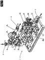
- the device of the invention for intercepting and redistributing drilling fluid in drilling rigs is indicated as a whole with 1 in Fig. 1 .
- This device comprises an inlet 2 for the direct flow F1 of the drilling fluid, an outlet 3 for the flow F2 of the fluid coming from the string of drill rods and an outlet 4 of the radial flow F3 of fluid from the same drill string, during the step to add an extension section to the drill string.
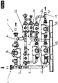
- the drilling fluid circulating in the device 1 can be mud, water or the like, which is circulated in the device of Figs. 1 and 2 passing through a main chamber 5, a first auxiliary chamber 6 and a second auxiliary chamber 7, all in fluid communication with one another.
- the flow F1 entering the main chamber 5 is transferred to the first auxiliary chamber 6 passing through a flow control valve 8 and a pressure relief valve 9.
- the same flow F1 coming from the main chamber 5 also enters the second auxiliary chamber 7 passing through the respective flow control valve 10 and is transferred, from this chamber 7 to the first auxiliary chamber 6, passing through the flow control valve 11, which is provided to place the aforesaid auxiliary chambers 6 and 7 in communication.
- the first auxiliary chamber 6 also has a pressure relief valve 12, while the second auxiliary chamber 7 has a flow control valve13, a pressure valve14 and a discharge valve 15.
- auxiliary chambers 6 and 7 are placed in communication with each other through the valve 11, which allows the drilling fluid to circulate from the second chamber 7 towards the first chamber 6, to then be sent from here to the drilling system.
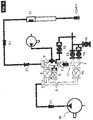
- the device 1 receives the flow F1 of drilling fluid supplied by a suitable piston pump 16, which first sends it to the main chamber 5 and, from here, both to the first auxiliary chamber 6 (passing through both its valves 8 and 9), and to the second auxiliary chamber 7, this time passing through the corresponding valve 10.
- the flow F1 supplied to the second auxiliary chamber 7 is also transferred inside the first auxiliary chamber 6, passing through the valve 11 that places the aforesaid auxiliary chambers in communication with each other during this drilling step. Therefore, a flow F2, the same as the flow F1 that exits from the first auxiliary chamber 6 of the device of the invention, is sent to the string of drill rods.
- the valve 12 of the chamber 6 and the valves 13, 14 of the chamber 7 are all closed.
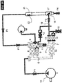
- the drilling system is placed exclusively in the radial circulation mode shown in Fig. 7 , both by closing the valves 8, 9 and 11, which in this way isolate the first auxiliary chamber 6 from the flow of drilling fluid circulating between the chambers 5 and 7, and by closing the valve 18 to the direct circulation.
- the flow of fluid supplied by the pump 16 is sent first to the main chamber 5, then to the second auxiliary chamber 7 (passing through the respective valve 10), then to the drill string 17 through the valves 13 and 14 (18 is in closed position), generating a radial drilling flow F3.
- the valve 12 of the first auxiliary chamber 6 is maintained open. In these conditions the flow F5 of fluid present in the line 20 is discharged towards the outside and, as this line is in depressurized state, it is in turn hermetically closed by the valve 18 placed inside the drill string 17 ( Fig. 7 ). At this point it is possible to add, to the line 20 which has thus been emptied of circulating fluid, a supplementary rod 21 for extension of the drill string 17, also equipped with its own radial valve 22 ( Fig. 8 ).
- the extension rod 21 and the respective supply line 20 are filled with drilling fluid supplied through a filling valve 24 of the first auxiliary chamber 6, by means of a flow F6 generated by a respective pump 23 ( Fig. 8 ). From this moment the valve 24 is closed and the valve 9 is opened, thereby pressurizing the first auxiliary chamber 6, the rod 21 and the respective line 20 of the direct drilling flow ( Fig. 9 ).
- valves 13 and 14 that control the radial flow exiting from the second auxiliary chamber 7 ( Fig. 11 ), thereby restoring the direct circulation shown in Fig. 4 .
- valve 15 by opening the valve 15 the pressure trapped in the radial channel 19 of this auxiliary chamber 7 is discharged, thereby allowing the aforesaid channel 19 to be disconnected from the rod 17 to restore the direct flow drilling mode.
Landscapes
- Engineering & Computer Science (AREA)
- Life Sciences & Earth Sciences (AREA)
- Geology (AREA)
- Mining & Mineral Resources (AREA)
- Mechanical Engineering (AREA)
- Physics & Mathematics (AREA)
- Environmental & Geological Engineering (AREA)
- Fluid Mechanics (AREA)
- General Life Sciences & Earth Sciences (AREA)
- Geochemistry & Mineralogy (AREA)
- Earth Drilling (AREA)
- Physical Or Chemical Processes And Apparatus (AREA)
Claims (11)
- Dispositif pour intercepter et redistribuer un fluide de forage dans des procédures de forage pour forer un puits en circulation continue dudit fluide, produit au moyen d'un flux direct (F1) et un flux radial (F3) à la chaîne de tiges de forage (17), du type comprenant une chambre principale (5) qui communique avec une première chambre auxiliaire (6) et avec une deuxième chambre auxiliaire (7), caractérisé en ce que, dans le mode de forage par flux direct précité (F1), lesdites chambres auxiliaires (6, 7) sont mises en communication de fluide l'une avec l'autre.
- Dispositif selon la revendication 1, caractérisé en ce qu'il est muni d'une vanne (11) pour mettre les chambres auxiliaires précitées (6, 7) en communication l'une avec l'autre.
- Dispositif selon la revendication 2, caractérisé en ce que ladite vanne (11) reçoit le fluide de forage à partir de la deuxième chambre auxiliaire (7) et le transfère à la première chambre auxiliaire (6) dans le mode par flux direct précité (F1).
- Dispositif selon la revendication 3, caractérisé en ce que ladite chambre principale (5) est munie d'une vanne de régulation de débit (8) et d'une soupape de surpression (9) pour mettre le fluide de forage en communication avec la première chambre auxiliaire (6), la chambre principale (5) ayant également une vanne de régulation de débit (10) pour transférer ce fluide de forage à la deuxième chambre auxiliaire (7).
- Dispositif selon la revendication 4, caractérisé en ce que ladite première chambre auxiliaire (6) est munie d'une soupape de surpression (12) et d'une vanne de remplissage (24).
- Dispositif selon la revendication 4, caractérisé en ce que ladite deuxième chambre auxiliaire (7) est munie d'une vanne de régulation de débit (13), d'une vanne de pression (14) et d'une vanne de décharge (15).
- Procédé de forage d'un puits en circulation continue de fluide de forage, exécuté avec le dispositif selon une ou plusieurs des revendications précédentes, du type qui fournit un flux direct (F1) et un flux radial (F3) de fluide à la chaîne de tiges de forage (17), caractérisé en ce que le flux précité (F1) produit une circulation directe de fluide de forage à travers les chambres (5, 6, 7) dudit dispositif, toutes mises en communications l'une avec l'autre.
- Procédé selon la revendication 7, caractérisé en ce que le flux de forage (F1) provenant de la deuxième chambre auxiliaire (7) est transmis à la première chambre auxiliaire (6), pour être successivement envoyé à la chaîne de tiges de forage (17).
- Procédé selon la revendication 7, caractérisé en ce que le flux de forage direct précité (F1) est délivré par une pompe respective (16) à la chambre principale précitée (5) et de celle-ci auxdites chambres auxiliaires (6, 7), maintenues en communication de fluide à la fois l'une avec l'autre et avec la chaîne de tiges de forage précitée (17).
- Procédé selon la revendication 7, caractérisé en ce que, dans les modes de pressurisation et dépressurisation, avant le flux combiné direct (F1) et radial (F3) de fluide de forage la chaîne de tiges (17), et dans le même le mode de flux combiné direct (F1) et radial (F3), le flux direct précité (F1) de fluide de forage est produit entre les chambres auxiliaires (6, 7) communiquant l'une avec l'autre.
- Procédé selon la revendication 7, caractérisé en ce que, durant l'insertion d'une nouvelle tige de forage dans la chaîne (17), et avant de rétablir le flux direct (F1), la ligne (20) pour la fourniture de fluide de forage à la chaîne étendue (17) est remplie avec ce fluide de forage.
Priority Applications (2)
| Application Number | Priority Date | Filing Date | Title |
|---|---|---|---|
| HRP20171492TT HRP20171492T1 (hr) | 2014-01-21 | 2015-01-09 | Postupak bušenja bušotine uz kontinuirano kruženje i uređaj za presretanje i preraspodjelu fluida koji se upotrebljava u tom postupku |
| PL15704202T PL3097251T3 (pl) | 2014-01-21 | 2015-01-09 | Sposób wykonywania odwiertu w obiegu ciągłym i urządzenie do przechwytywania i redystrybuowania płuczki stosowane w tym sposobie |
Applications Claiming Priority (2)
| Application Number | Priority Date | Filing Date | Title |
|---|---|---|---|
| ITMI20140070 | 2014-01-21 | ||
| PCT/EP2015/000035 WO2015110251A1 (fr) | 2014-01-21 | 2015-01-09 | Méthode de forage d'un puits en circulation continue et dispositif d'interception et de redistribution de fluide utilisé dans cette méthode |
Publications (2)
| Publication Number | Publication Date |
|---|---|
| EP3097251A1 EP3097251A1 (fr) | 2016-11-30 |
| EP3097251B1 true EP3097251B1 (fr) | 2017-07-26 |
Family
ID=50336436
Family Applications (1)
| Application Number | Title | Priority Date | Filing Date |
|---|---|---|---|
| EP15704202.9A Active EP3097251B1 (fr) | 2014-01-21 | 2015-01-09 | Méthode de forage d'un puits en circulation continue et dispositif d'interception et de redistribution de fluide utilisé dans cette méthode |
Country Status (9)
| Country | Link |
|---|---|
| US (1) | US10161206B2 (fr) |
| EP (1) | EP3097251B1 (fr) |
| CN (1) | CN105793517B (fr) |
| DK (1) | DK3097251T3 (fr) |
| EA (1) | EA030257B1 (fr) |
| ES (1) | ES2644519T3 (fr) |
| HR (1) | HRP20171492T1 (fr) |
| PL (1) | PL3097251T3 (fr) |
| WO (1) | WO2015110251A1 (fr) |
Families Citing this family (3)
| Publication number | Priority date | Publication date | Assignee | Title |
|---|---|---|---|---|
| US10094187B2 (en) * | 2014-01-16 | 2018-10-09 | Drillmec S.P.A. | Collector circuit for drilling fluid circulation system and method for diverting the circulation of the fluid |
| CA2974465C (fr) * | 2015-01-21 | 2019-03-05 | Schlumberger Canada Limited | Appareil pour couper et devier un flux de liquide en circulation sans coup de belier |
| CN111206895A (zh) * | 2020-03-29 | 2020-05-29 | 中国石油集团渤海钻探工程有限公司 | 精细控压钻井液流量监测系统及方法 |
Family Cites Families (7)
| Publication number | Priority date | Publication date | Assignee | Title |
|---|---|---|---|---|
| ITMI20070228A1 (it) * | 2007-02-08 | 2008-08-09 | Eni Spa | Apparecchiatura per intercettare e deviare un flusso di circolazione liquido |
| US8627890B2 (en) * | 2007-07-27 | 2014-01-14 | Weatherford/Lamb, Inc. | Rotating continuous flow sub |
| US8844653B2 (en) * | 2010-06-18 | 2014-09-30 | Dual Gradient Systems, Llc | Continuous circulating sub for drill strings |
| US9353587B2 (en) * | 2011-09-21 | 2016-05-31 | Weatherford Technology Holdings, Llc | Three-way flow sub for continuous circulation |
| CN202284457U (zh) * | 2011-10-18 | 2012-06-27 | 深圳市远东石油钻采工程有限公司 | 流道转换控制系统 |
| CN202913995U (zh) * | 2012-10-26 | 2013-05-01 | 中国石油天然气集团公司 | 钻井流体转向切换控制系统 |
| CN103397860B (zh) * | 2013-08-02 | 2015-09-02 | 张俊 | 泥浆分配远程控制器 |
-
2015
- 2015-01-09 EP EP15704202.9A patent/EP3097251B1/fr active Active
- 2015-01-09 WO PCT/EP2015/000035 patent/WO2015110251A1/fr not_active Ceased
- 2015-01-09 ES ES15704202.9T patent/ES2644519T3/es active Active
- 2015-01-09 PL PL15704202T patent/PL3097251T3/pl unknown
- 2015-01-09 EA EA201690981A patent/EA030257B1/ru unknown
- 2015-01-09 HR HRP20171492TT patent/HRP20171492T1/hr unknown
- 2015-01-09 DK DK15704202.9T patent/DK3097251T3/da active
- 2015-01-09 US US15/112,991 patent/US10161206B2/en active Active
- 2015-01-09 CN CN201580002858.4A patent/CN105793517B/zh active Active
Non-Patent Citations (1)
| Title |
|---|
| None * |
Also Published As
| Publication number | Publication date |
|---|---|
| US10161206B2 (en) | 2018-12-25 |
| PL3097251T3 (pl) | 2018-02-28 |
| CN105793517A (zh) | 2016-07-20 |
| WO2015110251A1 (fr) | 2015-07-30 |
| US20170002615A1 (en) | 2017-01-05 |
| DK3097251T3 (da) | 2017-11-06 |
| EP3097251A1 (fr) | 2016-11-30 |
| HK1225775A1 (zh) | 2017-09-15 |
| EA201690981A1 (ru) | 2016-10-31 |
| EA030257B1 (ru) | 2018-07-31 |
| ES2644519T3 (es) | 2017-11-29 |
| HRP20171492T1 (hr) | 2017-12-29 |
| CN105793517B (zh) | 2021-02-02 |
Similar Documents
| Publication | Publication Date | Title |
|---|---|---|
| RU2586129C1 (ru) | Система и способ управления давлением в кольцевом пространстве ствола скважины с применением газлифта в линии возврата бурового раствора | |
| EA019421B1 (ru) | Оборудование для перехвата и изменения направления жидкого циркулирующего потока | |
| WO2015091574A2 (fr) | Système de forage et procédé de fonctionnement d'un système de forage | |
| US10060210B2 (en) | Flow control downhole tool | |
| NO20140805A1 (no) | Hydraulisk kraftlader for innvendig stigerør | |
| EP3097251B1 (fr) | Méthode de forage d'un puits en circulation continue et dispositif d'interception et de redistribution de fluide utilisé dans cette méthode | |
| US11886206B2 (en) | Pressure regulator for fluid hammer reduction | |
| CN106545305B (zh) | 一种钻井液循环系统及其控制方法 | |
| NO20131579A1 (no) | Tetningssammenstilling for hybrid-tilbakekoblingssammenstilling ved anvendelse av fremgangsmåte og system for intervensjonsfri hydraulisk setting av utstyr ved underjordiske operasjoner | |
| WO2018107304A8 (fr) | Système d'écoulement de fluide sous pression pour marteau dth et marteau à circulation normale comprenant ledit système | |
| GB2566403A (en) | Systems and methods for managing fluid pressure in a borehole during drilling operations | |
| NO20120235A1 (no) | Stromningsmengdeavhengig stromningsstyringsanordning | |
| NO20181583A1 (en) | Method and system for managed pressure drilling | |
| US20150240578A1 (en) | Modular mud lift pump assembly | |
| GB2589498A (en) | A multi-functional sleeve completion system with return and reverse fluid path | |
| US20140262305A1 (en) | Control valve timing | |
| US20200318457A1 (en) | Tubing assembly for hydraulic shifting of sleeve without tool movement | |
| RU2549946C1 (ru) | Насосная пакерная система для многопластовой скважины | |
| RU2577345C2 (ru) | Способ управления давлением в стволе скважины при бурении с оптимизацией давления | |
| US20140262505A1 (en) | Automatic pump chamber control adjustment | |
| HK1225775B (zh) | 连续循环钻井方法和截留并再分配该方法所用流体的装置 | |
| US9175528B2 (en) | Decompression to fill pressure | |
| RU151717U1 (ru) | Гидравлический регулятор гарипова |
Legal Events
| Date | Code | Title | Description |
|---|---|---|---|
| PUAI | Public reference made under article 153(3) epc to a published international application that has entered the european phase |
Free format text: ORIGINAL CODE: 0009012 |
|
| 17P | Request for examination filed |
Effective date: 20160614 |
|
| AK | Designated contracting states |
Kind code of ref document: A1 Designated state(s): AL AT BE BG CH CY CZ DE DK EE ES FI FR GB GR HR HU IE IS IT LI LT LU LV MC MK MT NL NO PL PT RO RS SE SI SK SM TR |
|
| AX | Request for extension of the european patent |
Extension state: BA ME |
|
| GRAP | Despatch of communication of intention to grant a patent |
Free format text: ORIGINAL CODE: EPIDOSNIGR1 |
|
| DAX | Request for extension of the european patent (deleted) | ||
| INTG | Intention to grant announced |
Effective date: 20170224 |
|
| GRAS | Grant fee paid |
Free format text: ORIGINAL CODE: EPIDOSNIGR3 |
|
| GRAA | (expected) grant |
Free format text: ORIGINAL CODE: 0009210 |
|
| AK | Designated contracting states |
Kind code of ref document: B1 Designated state(s): AL AT BE BG CH CY CZ DE DK EE ES FI FR GB GR HR HU IE IS IT LI LT LU LV MC MK MT NL NO PL PT RO RS SE SI SK SM TR |
|
| REG | Reference to a national code |
Ref country code: GB Ref legal event code: FG4D |
|
| REG | Reference to a national code |
Ref country code: CH Ref legal event code: EP |
|
| REG | Reference to a national code |
Ref country code: AT Ref legal event code: REF Ref document number: 912557 Country of ref document: AT Kind code of ref document: T Effective date: 20170815 |
|
| REG | Reference to a national code |
Ref country code: IE Ref legal event code: FG4D |
|
| REG | Reference to a national code |
Ref country code: DE Ref legal event code: R096 Ref document number: 602015003773 Country of ref document: DE |
|
| REG | Reference to a national code |
Ref country code: HR Ref legal event code: TUEP Ref document number: P20171492 Country of ref document: HR |
|
| REG | Reference to a national code |
Ref country code: RO Ref legal event code: EPE |
|
| REG | Reference to a national code |
Ref country code: NL Ref legal event code: FP |
|
| REG | Reference to a national code |
Ref country code: DK Ref legal event code: T3 Effective date: 20171101 |
|
| REG | Reference to a national code |
Ref country code: LT Ref legal event code: MG4D |
|
| REG | Reference to a national code |
Ref country code: NO Ref legal event code: T2 Effective date: 20170726 |
|
| REG | Reference to a national code |
Ref country code: HR Ref legal event code: T1PR Ref document number: P20171492 Country of ref document: HR |
|
| REG | Reference to a national code |
Ref country code: FR Ref legal event code: PLFP Year of fee payment: 4 |
|
| PG25 | Lapsed in a contracting state [announced via postgrant information from national office to epo] |
Ref country code: LT Free format text: LAPSE BECAUSE OF FAILURE TO SUBMIT A TRANSLATION OF THE DESCRIPTION OR TO PAY THE FEE WITHIN THE PRESCRIBED TIME-LIMIT Effective date: 20170726 Ref country code: SE Free format text: LAPSE BECAUSE OF FAILURE TO SUBMIT A TRANSLATION OF THE DESCRIPTION OR TO PAY THE FEE WITHIN THE PRESCRIBED TIME-LIMIT Effective date: 20170726 Ref country code: FI Free format text: LAPSE BECAUSE OF FAILURE TO SUBMIT A TRANSLATION OF THE DESCRIPTION OR TO PAY THE FEE WITHIN THE PRESCRIBED TIME-LIMIT Effective date: 20170726 |
|
| PG25 | Lapsed in a contracting state [announced via postgrant information from national office to epo] |
Ref country code: BG Free format text: LAPSE BECAUSE OF FAILURE TO SUBMIT A TRANSLATION OF THE DESCRIPTION OR TO PAY THE FEE WITHIN THE PRESCRIBED TIME-LIMIT Effective date: 20171026 Ref country code: GR Free format text: LAPSE BECAUSE OF FAILURE TO SUBMIT A TRANSLATION OF THE DESCRIPTION OR TO PAY THE FEE WITHIN THE PRESCRIBED TIME-LIMIT Effective date: 20171027 Ref country code: IS Free format text: LAPSE BECAUSE OF FAILURE TO SUBMIT A TRANSLATION OF THE DESCRIPTION OR TO PAY THE FEE WITHIN THE PRESCRIBED TIME-LIMIT Effective date: 20171126 Ref country code: LV Free format text: LAPSE BECAUSE OF FAILURE TO SUBMIT A TRANSLATION OF THE DESCRIPTION OR TO PAY THE FEE WITHIN THE PRESCRIBED TIME-LIMIT Effective date: 20170726 Ref country code: RS Free format text: LAPSE BECAUSE OF FAILURE TO SUBMIT A TRANSLATION OF THE DESCRIPTION OR TO PAY THE FEE WITHIN THE PRESCRIBED TIME-LIMIT Effective date: 20170726 |
|
| PG25 | Lapsed in a contracting state [announced via postgrant information from national office to epo] |
Ref country code: CZ Free format text: LAPSE BECAUSE OF FAILURE TO SUBMIT A TRANSLATION OF THE DESCRIPTION OR TO PAY THE FEE WITHIN THE PRESCRIBED TIME-LIMIT Effective date: 20170726 |
|
| REG | Reference to a national code |
Ref country code: DE Ref legal event code: R097 Ref document number: 602015003773 Country of ref document: DE |
|
| PG25 | Lapsed in a contracting state [announced via postgrant information from national office to epo] |
Ref country code: SK Free format text: LAPSE BECAUSE OF FAILURE TO SUBMIT A TRANSLATION OF THE DESCRIPTION OR TO PAY THE FEE WITHIN THE PRESCRIBED TIME-LIMIT Effective date: 20170726 Ref country code: IT Free format text: LAPSE BECAUSE OF FAILURE TO SUBMIT A TRANSLATION OF THE DESCRIPTION OR TO PAY THE FEE WITHIN THE PRESCRIBED TIME-LIMIT Effective date: 20170726 Ref country code: SM Free format text: LAPSE BECAUSE OF FAILURE TO SUBMIT A TRANSLATION OF THE DESCRIPTION OR TO PAY THE FEE WITHIN THE PRESCRIBED TIME-LIMIT Effective date: 20170726 Ref country code: EE Free format text: LAPSE BECAUSE OF FAILURE TO SUBMIT A TRANSLATION OF THE DESCRIPTION OR TO PAY THE FEE WITHIN THE PRESCRIBED TIME-LIMIT Effective date: 20170726 |
|
| PLBE | No opposition filed within time limit |
Free format text: ORIGINAL CODE: 0009261 |
|
| STAA | Information on the status of an ep patent application or granted ep patent |
Free format text: STATUS: NO OPPOSITION FILED WITHIN TIME LIMIT |
|
| 26N | No opposition filed |
Effective date: 20180430 |
|
| PG25 | Lapsed in a contracting state [announced via postgrant information from national office to epo] |
Ref country code: SI Free format text: LAPSE BECAUSE OF FAILURE TO SUBMIT A TRANSLATION OF THE DESCRIPTION OR TO PAY THE FEE WITHIN THE PRESCRIBED TIME-LIMIT Effective date: 20170726 |
|
| PG25 | Lapsed in a contracting state [announced via postgrant information from national office to epo] |
Ref country code: LU Free format text: LAPSE BECAUSE OF NON-PAYMENT OF DUE FEES Effective date: 20180109 |
|
| REG | Reference to a national code |
Ref country code: IE Ref legal event code: MM4A |
|
| REG | Reference to a national code |
Ref country code: BE Ref legal event code: MM Effective date: 20180131 |
|
| PG25 | Lapsed in a contracting state [announced via postgrant information from national office to epo] |
Ref country code: BE Free format text: LAPSE BECAUSE OF NON-PAYMENT OF DUE FEES Effective date: 20180131 |
|
| REG | Reference to a national code |
Ref country code: HR Ref legal event code: ODRP Ref document number: P20171492 Country of ref document: HR Payment date: 20181218 Year of fee payment: 5 |
|
| PG25 | Lapsed in a contracting state [announced via postgrant information from national office to epo] |
Ref country code: IE Free format text: LAPSE BECAUSE OF NON-PAYMENT OF DUE FEES Effective date: 20180109 |
|
| PG25 | Lapsed in a contracting state [announced via postgrant information from national office to epo] |
Ref country code: MC Free format text: LAPSE BECAUSE OF FAILURE TO SUBMIT A TRANSLATION OF THE DESCRIPTION OR TO PAY THE FEE WITHIN THE PRESCRIBED TIME-LIMIT Effective date: 20170726 |
|
| REG | Reference to a national code |
Ref country code: HR Ref legal event code: ODRP Ref document number: P20171492 Country of ref document: HR Payment date: 20191230 Year of fee payment: 6 |
|
| PG25 | Lapsed in a contracting state [announced via postgrant information from national office to epo] |
Ref country code: TR Free format text: LAPSE BECAUSE OF FAILURE TO SUBMIT A TRANSLATION OF THE DESCRIPTION OR TO PAY THE FEE WITHIN THE PRESCRIBED TIME-LIMIT Effective date: 20170726 |
|
| PG25 | Lapsed in a contracting state [announced via postgrant information from national office to epo] |
Ref country code: PT Free format text: LAPSE BECAUSE OF FAILURE TO SUBMIT A TRANSLATION OF THE DESCRIPTION OR TO PAY THE FEE WITHIN THE PRESCRIBED TIME-LIMIT Effective date: 20170726 |
|
| PG25 | Lapsed in a contracting state [announced via postgrant information from national office to epo] |
Ref country code: MK Free format text: LAPSE BECAUSE OF NON-PAYMENT OF DUE FEES Effective date: 20170726 Ref country code: HU Free format text: LAPSE BECAUSE OF FAILURE TO SUBMIT A TRANSLATION OF THE DESCRIPTION OR TO PAY THE FEE WITHIN THE PRESCRIBED TIME-LIMIT; INVALID AB INITIO Effective date: 20150109 Ref country code: CY Free format text: LAPSE BECAUSE OF FAILURE TO SUBMIT A TRANSLATION OF THE DESCRIPTION OR TO PAY THE FEE WITHIN THE PRESCRIBED TIME-LIMIT Effective date: 20170726 |
|
| REG | Reference to a national code |
Ref country code: HR Ref legal event code: ODRP Ref document number: P20171492 Country of ref document: HR Payment date: 20201228 Year of fee payment: 7 |
|
| REG | Reference to a national code |
Ref country code: AT Ref legal event code: UEP Ref document number: 912557 Country of ref document: AT Kind code of ref document: T Effective date: 20170726 |
|
| REG | Reference to a national code |
Ref country code: HR Ref legal event code: ODRP Ref document number: P20171492 Country of ref document: HR Payment date: 20211227 Year of fee payment: 8 |
|
| REG | Reference to a national code |
Ref country code: HR Ref legal event code: ODRP Ref document number: P20171492 Country of ref document: HR Payment date: 20221220 Year of fee payment: 9 |
|
| REG | Reference to a national code |
Ref country code: HR Ref legal event code: ODRP Ref document number: P20171492 Country of ref document: HR Payment date: 20231228 Year of fee payment: 10 |
|
| PGFP | Annual fee paid to national office [announced via postgrant information from national office to epo] |
Ref country code: RO Payment date: 20231229 Year of fee payment: 10 Ref country code: HR Payment date: 20231228 Year of fee payment: 10 |
|
| PGFP | Annual fee paid to national office [announced via postgrant information from national office to epo] |
Ref country code: NL Payment date: 20240126 Year of fee payment: 10 Ref country code: ES Payment date: 20240208 Year of fee payment: 10 |
|
| PGFP | Annual fee paid to national office [announced via postgrant information from national office to epo] |
Ref country code: AT Payment date: 20240110 Year of fee payment: 10 |
|
| PGFP | Annual fee paid to national office [announced via postgrant information from national office to epo] |
Ref country code: DE Payment date: 20240110 Year of fee payment: 10 Ref country code: CH Payment date: 20240202 Year of fee payment: 10 |
|
| PGFP | Annual fee paid to national office [announced via postgrant information from national office to epo] |
Ref country code: PL Payment date: 20240108 Year of fee payment: 10 Ref country code: MT Payment date: 20240125 Year of fee payment: 10 Ref country code: FR Payment date: 20240124 Year of fee payment: 10 |
|
| PGFP | Annual fee paid to national office [announced via postgrant information from national office to epo] |
Ref country code: AL Payment date: 20240131 Year of fee payment: 10 |
|
| REG | Reference to a national code |
Ref country code: HR Ref legal event code: PBON Ref document number: P20171492 Country of ref document: HR Effective date: 20250109 |
|
| REG | Reference to a national code |
Ref country code: DE Ref legal event code: R119 Ref document number: 602015003773 Country of ref document: DE |
|
| REG | Reference to a national code |
Ref country code: CH Ref legal event code: PL |
|
| REG | Reference to a national code |
Ref country code: NL Ref legal event code: MM Effective date: 20250201 |
|
| REG | Reference to a national code |
Ref country code: AT Ref legal event code: MM01 Ref document number: 912557 Country of ref document: AT Kind code of ref document: T Effective date: 20250109 |
|
| PG25 | Lapsed in a contracting state [announced via postgrant information from national office to epo] |
Ref country code: DE Free format text: LAPSE BECAUSE OF NON-PAYMENT OF DUE FEES Effective date: 20250801 |
|
| PG25 | Lapsed in a contracting state [announced via postgrant information from national office to epo] |
Ref country code: NL Free format text: LAPSE BECAUSE OF NON-PAYMENT OF DUE FEES Effective date: 20250201 |
|
| PG25 | Lapsed in a contracting state [announced via postgrant information from national office to epo] |
Ref country code: HR Free format text: LAPSE BECAUSE OF NON-PAYMENT OF DUE FEES Effective date: 20250109 |
|
| PG25 | Lapsed in a contracting state [announced via postgrant information from national office to epo] |
Ref country code: FR Free format text: LAPSE BECAUSE OF NON-PAYMENT OF DUE FEES Effective date: 20250131 Ref country code: AT Free format text: LAPSE BECAUSE OF NON-PAYMENT OF DUE FEES Effective date: 20250109 |
|
| PG25 | Lapsed in a contracting state [announced via postgrant information from national office to epo] |
Ref country code: CH Free format text: LAPSE BECAUSE OF NON-PAYMENT OF DUE FEES Effective date: 20250131 |
|
| PG25 | Lapsed in a contracting state [announced via postgrant information from national office to epo] |
Ref country code: RO Free format text: LAPSE BECAUSE OF NON-PAYMENT OF DUE FEES Effective date: 20250109 |
|
| PGFP | Annual fee paid to national office [announced via postgrant information from national office to epo] |
Ref country code: DK Payment date: 20251223 Year of fee payment: 12 |
|
| REG | Reference to a national code |
Ref country code: ES Ref legal event code: FD2A Effective date: 20260227 |
|
| PGFP | Annual fee paid to national office [announced via postgrant information from national office to epo] |
Ref country code: GB Payment date: 20260126 Year of fee payment: 12 |
|
| PG25 | Lapsed in a contracting state [announced via postgrant information from national office to epo] |
Ref country code: ES Free format text: LAPSE BECAUSE OF NON-PAYMENT OF DUE FEES Effective date: 20250110 |
|
| PGFP | Annual fee paid to national office [announced via postgrant information from national office to epo] |
Ref country code: NO Payment date: 20260120 Year of fee payment: 12 |