EP3097268B1 - Aube pour un moteur à turbine à gaz et procédé associé d'amortisation - Google Patents
Aube pour un moteur à turbine à gaz et procédé associé d'amortisation Download PDFInfo
- Publication number
- EP3097268B1 EP3097268B1 EP15740454.2A EP15740454A EP3097268B1 EP 3097268 B1 EP3097268 B1 EP 3097268B1 EP 15740454 A EP15740454 A EP 15740454A EP 3097268 B1 EP3097268 B1 EP 3097268B1
- Authority
- EP
- European Patent Office
- Prior art keywords
- blade
- recited
- spring arm
- cantilever spring
- bridge
- Prior art date
- Legal status (The legal status is an assumption and is not a legal conclusion. Google has not performed a legal analysis and makes no representation as to the accuracy of the status listed.)
- Active
Links
Images


Classifications
-
- F—MECHANICAL ENGINEERING; LIGHTING; HEATING; WEAPONS; BLASTING
- F01—MACHINES OR ENGINES IN GENERAL; ENGINE PLANTS IN GENERAL; STEAM ENGINES
- F01D—NON-POSITIVE DISPLACEMENT MACHINES OR ENGINES, e.g. STEAM TURBINES
- F01D5/00—Blades; Blade-carrying members; Heating, heat-insulating, cooling or antivibration means on the blades or the members
- F01D5/12—Blades
- F01D5/14—Form or construction
- F01D5/16—Form or construction for counteracting blade vibration
-
- B—PERFORMING OPERATIONS; TRANSPORTING
- B22—CASTING; POWDER METALLURGY
- B22F—WORKING METALLIC POWDER; MANUFACTURE OF ARTICLES FROM METALLIC POWDER; MAKING METALLIC POWDER; APPARATUS OR DEVICES SPECIALLY ADAPTED FOR METALLIC POWDER
- B22F10/00—Additive manufacturing of workpieces or articles from metallic powder
-
- B—PERFORMING OPERATIONS; TRANSPORTING
- B22—CASTING; POWDER METALLURGY
- B22F—WORKING METALLIC POWDER; MANUFACTURE OF ARTICLES FROM METALLIC POWDER; MAKING METALLIC POWDER; APPARATUS OR DEVICES SPECIALLY ADAPTED FOR METALLIC POWDER
- B22F5/00—Manufacture of workpieces or articles from metallic powder characterised by the special shape of the product
- B22F5/04—Manufacture of workpieces or articles from metallic powder characterised by the special shape of the product of turbine blades
-
- B—PERFORMING OPERATIONS; TRANSPORTING
- B22—CASTING; POWDER METALLURGY
- B22F—WORKING METALLIC POWDER; MANUFACTURE OF ARTICLES FROM METALLIC POWDER; MAKING METALLIC POWDER; APPARATUS OR DEVICES SPECIALLY ADAPTED FOR METALLIC POWDER
- B22F7/00—Manufacture of composite layers, workpieces, or articles, comprising metallic powder, by sintering the powder, with or without compacting wherein at least one part is obtained by sintering or compression
- B22F7/06—Manufacture of composite layers, workpieces, or articles, comprising metallic powder, by sintering the powder, with or without compacting wherein at least one part is obtained by sintering or compression of composite workpieces or articles from parts, e.g. to form tipped tools
-
- F—MECHANICAL ENGINEERING; LIGHTING; HEATING; WEAPONS; BLASTING
- F04—POSITIVE - DISPLACEMENT MACHINES FOR LIQUIDS; PUMPS FOR LIQUIDS OR ELASTIC FLUIDS
- F04D—NON-POSITIVE-DISPLACEMENT PUMPS
- F04D29/00—Details, component parts, or accessories
- F04D29/26—Rotors specially for elastic fluids
- F04D29/32—Rotors specially for elastic fluids for axial flow pumps
- F04D29/325—Rotors specially for elastic fluids for axial flow pumps for axial flow fans
-
- F—MECHANICAL ENGINEERING; LIGHTING; HEATING; WEAPONS; BLASTING
- F04—POSITIVE - DISPLACEMENT MACHINES FOR LIQUIDS; PUMPS FOR LIQUIDS OR ELASTIC FLUIDS
- F04D—NON-POSITIVE-DISPLACEMENT PUMPS
- F04D29/00—Details, component parts, or accessories
- F04D29/26—Rotors specially for elastic fluids
- F04D29/32—Rotors specially for elastic fluids for axial flow pumps
- F04D29/38—Blades
- F04D29/388—Blades characterised by construction
-
- F—MECHANICAL ENGINEERING; LIGHTING; HEATING; WEAPONS; BLASTING
- F04—POSITIVE - DISPLACEMENT MACHINES FOR LIQUIDS; PUMPS FOR LIQUIDS OR ELASTIC FLUIDS
- F04D—NON-POSITIVE-DISPLACEMENT PUMPS
- F04D29/00—Details, component parts, or accessories
- F04D29/66—Combating cavitation, whirls, noise, vibration or the like; Balancing
- F04D29/661—Combating cavitation, whirls, noise, vibration or the like; Balancing especially adapted for elastic fluid pumps
- F04D29/668—Combating cavitation, whirls, noise, vibration or the like; Balancing especially adapted for elastic fluid pumps damping or preventing mechanical vibrations
-
- B—PERFORMING OPERATIONS; TRANSPORTING
- B22—CASTING; POWDER METALLURGY
- B22F—WORKING METALLIC POWDER; MANUFACTURE OF ARTICLES FROM METALLIC POWDER; MAKING METALLIC POWDER; APPARATUS OR DEVICES SPECIALLY ADAPTED FOR METALLIC POWDER
- B22F10/00—Additive manufacturing of workpieces or articles from metallic powder
- B22F10/10—Formation of a green body
- B22F10/12—Formation of a green body by photopolymerisation, e.g. stereolithography [SLA] or digital light processing [DLP]
-
- B—PERFORMING OPERATIONS; TRANSPORTING
- B22—CASTING; POWDER METALLURGY
- B22F—WORKING METALLIC POWDER; MANUFACTURE OF ARTICLES FROM METALLIC POWDER; MAKING METALLIC POWDER; APPARATUS OR DEVICES SPECIALLY ADAPTED FOR METALLIC POWDER
- B22F10/00—Additive manufacturing of workpieces or articles from metallic powder
- B22F10/20—Direct sintering or melting
- B22F10/25—Direct deposition of metal particles, e.g. direct metal deposition [DMD] or laser engineered net shaping [LENS]
-
- B—PERFORMING OPERATIONS; TRANSPORTING
- B22—CASTING; POWDER METALLURGY
- B22F—WORKING METALLIC POWDER; MANUFACTURE OF ARTICLES FROM METALLIC POWDER; MAKING METALLIC POWDER; APPARATUS OR DEVICES SPECIALLY ADAPTED FOR METALLIC POWDER
- B22F10/00—Additive manufacturing of workpieces or articles from metallic powder
- B22F10/20—Direct sintering or melting
- B22F10/28—Powder bed fusion, e.g. selective laser melting [SLM] or electron beam melting [EBM]
-
- F—MECHANICAL ENGINEERING; LIGHTING; HEATING; WEAPONS; BLASTING
- F05—INDEXING SCHEMES RELATING TO ENGINES OR PUMPS IN VARIOUS SUBCLASSES OF CLASSES F01-F04
- F05B—INDEXING SCHEME RELATING TO WIND, SPRING, WEIGHT, INERTIA OR LIKE MOTORS, TO MACHINES OR ENGINES FOR LIQUIDS COVERED BY SUBCLASSES F03B, F03D AND F03G
- F05B2220/00—Application
- F05B2220/30—Application in turbines
- F05B2220/302—Application in turbines in gas turbines
-
- F—MECHANICAL ENGINEERING; LIGHTING; HEATING; WEAPONS; BLASTING
- F05—INDEXING SCHEMES RELATING TO ENGINES OR PUMPS IN VARIOUS SUBCLASSES OF CLASSES F01-F04
- F05B—INDEXING SCHEME RELATING TO WIND, SPRING, WEIGHT, INERTIA OR LIKE MOTORS, TO MACHINES OR ENGINES FOR LIQUIDS COVERED BY SUBCLASSES F03B, F03D AND F03G
- F05B2230/00—Manufacture
- F05B2230/30—Manufacture with deposition of material
- F05B2230/31—Layer deposition
-
- F—MECHANICAL ENGINEERING; LIGHTING; HEATING; WEAPONS; BLASTING
- F05—INDEXING SCHEMES RELATING TO ENGINES OR PUMPS IN VARIOUS SUBCLASSES OF CLASSES F01-F04
- F05B—INDEXING SCHEME RELATING TO WIND, SPRING, WEIGHT, INERTIA OR LIKE MOTORS, TO MACHINES OR ENGINES FOR LIQUIDS COVERED BY SUBCLASSES F03B, F03D AND F03G
- F05B2230/00—Manufacture
- F05B2230/60—Assembly methods
-
- F—MECHANICAL ENGINEERING; LIGHTING; HEATING; WEAPONS; BLASTING
- F05—INDEXING SCHEMES RELATING TO ENGINES OR PUMPS IN VARIOUS SUBCLASSES OF CLASSES F01-F04
- F05D—INDEXING SCHEME FOR ASPECTS RELATING TO NON-POSITIVE-DISPLACEMENT MACHINES OR ENGINES, GAS-TURBINES OR JET-PROPULSION PLANTS
- F05D2230/00—Manufacture
- F05D2230/20—Manufacture essentially without removing material
- F05D2230/22—Manufacture essentially without removing material by sintering
-
- F—MECHANICAL ENGINEERING; LIGHTING; HEATING; WEAPONS; BLASTING
- F05—INDEXING SCHEMES RELATING TO ENGINES OR PUMPS IN VARIOUS SUBCLASSES OF CLASSES F01-F04
- F05D—INDEXING SCHEME FOR ASPECTS RELATING TO NON-POSITIVE-DISPLACEMENT MACHINES OR ENGINES, GAS-TURBINES OR JET-PROPULSION PLANTS
- F05D2230/00—Manufacture
- F05D2230/30—Manufacture with deposition of material
- F05D2230/31—Layer deposition
-
- Y—GENERAL TAGGING OF NEW TECHNOLOGICAL DEVELOPMENTS; GENERAL TAGGING OF CROSS-SECTIONAL TECHNOLOGIES SPANNING OVER SEVERAL SECTIONS OF THE IPC; TECHNICAL SUBJECTS COVERED BY FORMER USPC CROSS-REFERENCE ART COLLECTIONS [XRACs] AND DIGESTS
- Y02—TECHNOLOGIES OR APPLICATIONS FOR MITIGATION OR ADAPTATION AGAINST CLIMATE CHANGE
- Y02P—CLIMATE CHANGE MITIGATION TECHNOLOGIES IN THE PRODUCTION OR PROCESSING OF GOODS
- Y02P10/00—Technologies related to metal processing
- Y02P10/25—Process efficiency
-
- Y—GENERAL TAGGING OF NEW TECHNOLOGICAL DEVELOPMENTS; GENERAL TAGGING OF CROSS-SECTIONAL TECHNOLOGIES SPANNING OVER SEVERAL SECTIONS OF THE IPC; TECHNICAL SUBJECTS COVERED BY FORMER USPC CROSS-REFERENCE ART COLLECTIONS [XRACs] AND DIGESTS
- Y02—TECHNOLOGIES OR APPLICATIONS FOR MITIGATION OR ADAPTATION AGAINST CLIMATE CHANGE
- Y02T—CLIMATE CHANGE MITIGATION TECHNOLOGIES RELATED TO TRANSPORTATION
- Y02T50/00—Aeronautics or air transport
- Y02T50/60—Efficient propulsion technologies, e.g. for aircraft
Definitions
- the present disclosure relates to a gas turbine engine and, more particularly, to an airfoil therefor.
- Gas turbine engines such as those that power modern commercial and military aircraft, generally include a compressor section to pressurize an airflow, a combustor section to burn a hydrocarbon fuel in the presence of the pressurized air, and a turbine section to extract energy from the resultant combustion gases.
- Gas turbine engines typically have rows of circumferentially spaced airfoils mounted on respective rotor disks for rotation about an engine axis.
- Advanced configurations feature shroud-less hollow airfoils manufactured of lightweight materials.
- the airfoils are designed to high tolerances to accommodate significant operational requirements such as crosswinds and inlet distortion. These requirements result in airfoils that may be prone to high vibratory responses and possible aeroelastic instability within some operational speed ranges that may result in flutter.
- Airfoil flutter is the result of complex interactions between fluid flow, stiffness, and inertial forces on an airfoil. Every airfoil has a critical speed, beyond which flutter will occur.
- the airfoils are designed for sufficient torsional stiffness, bending stiffness, and structural damping to avoid excitation. However, airfoils stiff enough to provide adequate flutter margin may also result in an airfoil relative heavy in weight. Some airfoils also include dampers such as particle filled cavities, which, although at least partially effective, further increase airfoil weight.
- EP 2466072A2 and US 2007/081894A1 disclose features of the preamble of claim 1.
- a blade for a gas turbine engine is claimed in claim 1.
- the airfoil portion extends from a platform portion of a fan blade.
- the cantilever spring arm extends from a base between a concave pressure side and a convex suction side.
- the rub surface pad is located between the friction bridge and a motion limit bridge between the concave pressure side and the convex suction side.
- a clip is removably mounted to at least one of the rub surface pad and the friction bridge.
- a clip is additively manufactured to the friction bridge.
- the clip is additively manufactured of a material different than the friction bridge.
- a clip is additively manufactured to the rub surface pad.
- the clip is additively manufactured of a material different than the rub surface pad.
- a method of damping a blade of a gas turbine engine, according to another aspect of the present invention, is claimed in claim 8.
- the centrifugal load generated by rotation of the blade is on the order of about thirty and about sixty thousand Gs.
- the rub surface pad and the friction bridge include a fretting surface coating.
- the method includes additively manufacturing the concave pressure side and the convex suction side.
- the method includes additively manufacturing the cantilever spring arm and the friction bridge with the concave pressure side and the convex suction side.
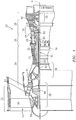
- FIG. 1 schematically illustrates a gas turbine engine 20.
- the gas turbine engine 20 is disclosed herein as a two-spool turbo fan that generally incorporates a fan section 22, a compressor section 24, a combustor section 26 and a turbine section 28.
- Alternative engine architectures 200 might include an augmentor section 12, an exhaust duct section 14 and a nozzle section 16 in addition to the fan section 22', compressor section 24', combustor section 26' and turbine section 28' (see FIG. 2 ) among other systems or features.
- the fan section 22 drives air along a bypass flowpath and into the compressor section 24.
- the compressor section 24 drives air along a core flowpath for compression and communication into the combustor section 26, which then expands and directs the air through the turbine section 28.
- turbofan in the disclosed non-limiting embodiment, it should be understood that the concepts described herein are not limited to use with turbofans as the teachings may be applied to other types of turbine engines such as a turbojets, turboshafts, and three-spool (plus fan) turbofans wherein an intermediate spool includes an Intermediate Pressure Compressor ("IPC") between a Low Pressure Compressor (“LPC”) and a High Pressure Compressor (“HPC”), and an Intermediate Pressure Turbine (“IPT”) between a High Pressure Turbine (“HPT”) and the Low Pressure Turbine (“LPT”).
- IPC Intermediate Pressure Compressor
- LPC Low Pressure Compressor
- HPC High Pressure Compressor
- IPT Intermediate Pressure Turbine
- the engine 20 generally includes a low spool 30 and a high spool 32 mounted for rotation about an engine central longitudinal axis A relative to an engine static structure 36 via several bearing structures 38.
- the low spool 30 generally includes an inner shaft 40 that interconnects a fan 42, a low pressure compressor (“LPC”) 44 and a low pressure turbine (“LPT”) 46.
- the inner shaft 40 may drive the fan 42 directly or through a geared architecture 48 to drive the fan 42 at a lower speed than the low spool 30.
- An exemplary reduction transmission is an epicyclic transmission, namely a planetary or star gear system.
- the high spool 32 includes an outer shaft 50 that interconnects a high pressure compressor (“HPC”) 52 and a high pressure turbine (“HPT”) 54.
- a combustor 56 is arranged between the HPC 52 and the HPT 54.
- the inner shaft 40 and the outer shaft 50 are concentric and rotate about the engine central longitudinal axis A which is collinear with their longitudinal axes.
- Core airflow is compressed by the LPC 44 then the HPC 52, mixed with the fuel and burned in the combustor 56, then expanded over the HPT 54 and the LPT 46.
- the LPT 46 and HPT 54 rotationally drive the respective low spool 30 and high spool 32 in response to the expansion.
- the main engine shafts 40, 50 are supported at a plurality of points by the bearing systems 38 within the static structure 36.
- the gas turbine engine 20 is a high-bypass geared aircraft engine.
- the gas turbine engine 20 bypass ratio is greater than about six (6:1).
- the geared architecture 48 can include an epicyclic gear train, such as a planetary gear system or other gear system.
- the example epicyclic gear train has a gear reduction ratio of greater than about 2.3, and in another example is greater than about 2.5:1.
- the geared turbofan enables operation of the low spool 30 at higher speeds which can increase the operational efficiency of the LPC 44 and LPT 46 and render increased pressure in a fewer number of stages.
- a pressure ratio associated with the LPT 46 is pressure measured prior to the inlet of the LPT 46 as related to the pressure at the outlet of the LPT 46 prior to an exhaust nozzle of the gas turbine engine 20.
- the bypass ratio of the gas turbine engine 20 is greater than about ten (10:1)
- the fan diameter is significantly larger than that of the LPC 44
- the LPT 46 has a pressure ratio that is greater than about five (5:1). It should be understood, however, that the above parameters are only exemplary of one embodiment of a geared architecture engine and that the present disclosure is applicable to other gas turbine engines including direct drive turbofans.
- a significant amount of thrust is provided by the bypass flow path due to the high bypass ratio.
- the fan section 22 of the gas turbine engine 20 is designed for a particular flight condition - typically cruise at about 0.8 Mach and about 35,000 feet (10,668m). This flight condition, with the gas turbine engine 20 at its best fuel consumption, is also known as bucket cruise Thrust Specific Fuel Consumption (TSFC).
- TSFC Thrust Specific Fuel Consumption
- Fan Pressure Ratio is the pressure ratio across a blade of the fan section 22 without the use of a Fan Exit Guide Vane system.
- the low Fan Pressure Ratio according to one non-limiting embodiment of the example gas turbine engine 20 is less than 1.45.
- Low Corrected Fan Tip Speed is the actual fan tip speed divided by an industry standard temperature correction of ("Tram" / 518.7 °R) 0.5 ([°R] is equal to [K] x 9/5).
- the Low Corrected Fan Tip Speed according to one non-limiting embodiment of the example gas turbine engine 20 is less than about 1150 fps (351 m/s).
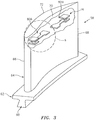
- the fan section 22 includes a plurality of circumferentially spaced fan blades 58 which may be made of a high-strength, low weight material such as an aluminum alloy, titanium alloy, composite material or combinations thereof. It should be understood that although a single fan stage typical of a high bypass gas turbofan engine architecture is illustrated and described in the disclosed embodiment, other stages which have other blades inclusive but not limited to fan blades, high pressure compressor blades and low pressure compressor blades may also benefit herefrom.
- each fan blade 58 generally includes an innermost root portion 60, an intermediate platform portion 62, and an outermost airfoil portion 64.
- the root portion 60 defines an attachment such as an inverted "fir tree"-like shape, bulb, or dovetail so the fan blade 58 is slidably received in a complimentary configured recess provided in a fan rotor 59 (see FIG. 1 ).
- the platform portion 62 generally separates the root portion 60 and the airfoil portion 64 to define an inner boundary of the air flow path.
- the airfoil portion 64 defines a blade chord between a leading edge 66, which may include various forward and/or aft sweep configurations, and a trailing edge 68.
- a concave pressure side 70 and a convex suction side 72 are defined between the leading edge 66 and the trailing edge 68.
- a fan blade 58 is illustrated in the disclosed non-limiting embodiment, it should be understood that compressor blades, turbofan blades, turboprop propeller blades, tilt rotor props and other airfoils may benefit herefrom.
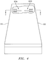
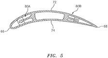
- the airfoil portion 64 may be at least partially hollow within one or more internal cavities 74 that include a damper 80 (two shown as 80A, 80B).
- the fan blade 58 is typically manufactured in at least two sides such as the concave pressure side 70 and the convex suction side 72 which are assembled together to form the internal cavity 74 or may be readily manufactured with a rapid manufacturing processes such as Sterolithography (SLS), Direct Selective Laser Sintering (DSLS), Direct Metal Laser Sintering (DMLS), Electron Beam Sintering (EBS), Electron Beam Melting (EBM), Laser Engineered Net Shaping (LENS), Laser Net Shape Manufacturing (LNSM) and Direct Metal Deposition (DMD).
- SLS Sterolithography
- DSLS Direct Selective Laser Sintering
- DMLS Direct Metal Laser Sintering
- EBS Electron Beam Sintering
- EBM Electron Beam Melting
- LENS Laser Engineered Net Shaping
- LNSM Laser Net Shape Manufacturing
- DMD Direct Metal De
- alloy and/or ceramic powder material such as, but not limited to, 625 Alloy, 718 Alloy, 230 Alloy, stainless steel, tool steel, cobalt chrome, titanium, nickel, aluminum and others in powder or wire material form.
- Alloys such as 625, 718 and 230 may be used for parts that operate in high temperature environments, such as, for example, environments typically encountered by aerospace and gas turbine engine components.
- the additive manufacturing process facilitates manufacture of the relatively complex internal geometry to minimize assembly details and multi-component construction.
- the additive manufacturing process fabricates or "grows" components using three-dimensional information, for example, a three-dimensional computer model.
- the three-dimensional information is converted into a plurality of slices, each slice defining a cross section of the component for a predetermined height of the slice.
- the additive manufactured component is then "grown" slice by slice, or layer by layer, until finished.
- Each layer may be between about 0.0005 - 0.015 inches (0.0127 - 0.381 mm).
- the damper 80 (two shown as 80A, 80B) is located within the internal cavity 74. Generally, transverse and adjacent to the leading edge 66 and the trailing edge 68 (see FIGS. 4 and 5 ). Although a particular number, orientation and location for each damper 80 is illustrated, it should be appreciated that any number, orientation and location will also benefit herefrom.
- the damper 80 can be economically co-grown within the cavity 74 of the additively manufactured fan blade in a manner that will reduce the nominal stiffness requirement of the airfoil structure to provide adequate flutter margin.
- each damper 80 generally includes a cantilever spring arm 82 that terminates with a friction head 84, a friction bridge 86 and a motion limit bridge 88.
- the cantilever spring arm 82 extends from a base 90 that extends across the cavity 74 between the concave pressure side 70 and the convex suction side 72.
- the friction bridge 86 and the motion limit bridge 88 extend between the concave pressure side 70 and the convex suction side 72 such that the rub surface pad 84 is located therebetween.
- the base 90, the friction bridge 86 and the motion limit bridge 88 may be integrated with the internal stiffening and shear web structure typical of a hollow metal fan blade. That is, the cantilever spring arm 82 may extend from otherwise existent and purposed structure.
- the cantilever spring arm 82 is shaped, sized, and oriented to deflect under centrifugal G loading (illustrated schematically by arrow G) across a gap between the rub surface pad 84 and the friction bridge 86 when the fan blade is rotating during engine operation to allow the faying surfaces of the rub surface pad 84 to make contact at a desired contact force with the friction bridge 86.
- the fan blade 58 in one example, typically experiences between thirty and sixty thousand Gs and the spring rate of the cantilever spring arm 82 and the volume of the rub surface pad 84 at the end of the spring arm 82 may be tailored to provide the desired contact force at an operating speed of interest to provide torsional damping and thereby reduce flutter.
- the rub surface pad 84 and the friction bridge 86 may be faced with fretting resistant coating 90 such as L 605 Cobalt alloy or Inconel 718 combinations that resist fretting to increase service life.
- fretting resistant coating 90 such as L 605 Cobalt alloy or Inconel 718 combinations that resist fretting to increase service life.
- the surface finish of the faying surfaces may additionally be tailored to the desired value during the growing process by laser glazing, mechanical metal working, or other methods.
- either or both the rub surface pad 84 and the friction bridge 86 may receive a clip 92 that forms the rub surfaces. That is, the clip 92 forms a fretting resistant surface as well as facilitate maintenance over the surface life of the blade which may be on the order of sixty to eighty thousand hours. It should be appreciated that the clip 92 may be additively manufactured of a material different than the material to which it is attached. That is, the clip 92 may be additively manufactured in situ but of a different material.
Landscapes
- Engineering & Computer Science (AREA)
- Mechanical Engineering (AREA)
- General Engineering & Computer Science (AREA)
- Manufacturing & Machinery (AREA)
- Chemical & Material Sciences (AREA)
- Materials Engineering (AREA)
- Composite Materials (AREA)
- Structures Of Non-Positive Displacement Pumps (AREA)
- Turbine Rotor Nozzle Sealing (AREA)
Claims (12)
- Aube (58) pour un moteur à turbine à gaz (20), comprenant :une partie de surface portante (64) avec au moins une cavité interne (74) ; etun amortisseur (80) situé à l'intérieur de la cavité interne (74), l'amortisseur (80) comportant un bras à ressort en porte-à-faux (82), dans laquelle l'aube (58) est une aube de soufflante et le bras à ressort en porte-à-faux (82) se termine par un tampon de surface de frottement (84) adjacent à une passerelle de friction (86) entre un côté de pression concave (70) et un côté d'aspiration convexe (72) de la partie de surface portante (64), caractérisé en ce que le bras de ressort en porte-à-faux (82) s'étend vers un bord d'attaque ou de fuite (66, 68) de la partie de surface portante (64).
- Aube selon la revendication 1, dans laquelle la partie de surface portante (64) s'étend à partir d'une partie de plateforme (62) de l'aube de soufflante (58).
- Aube selon la revendication 1 ou 2, dans laquelle le bras à ressort en porte-à-faux (82) s'étend à partir d'une base (90) entre le côté de pression concave (70) et le côté d'aspiration convexe (72).
- Aube selon une quelconque revendication précédente, dans laquelle le tampon de surface de frottement (84) est situé entre la passerelle de friction (86) et une passerelle de limitation de mouvement (88) entre le côté de pression concave (70) et le côté d'aspiration convexe (72).
- Aube selon une quelconque revendication précédente, comprenant en outre une pince (92) montée de manière amovible sur au moins l'un des tampons de surface de frottement (84) et la passerelle de friction (86).
- Aube selon une quelconque revendication précédente, comprenant en outre une pince (92) fabriquée de manière additive sur la passerelle de friction (86), la pince (92) étant fabriquée de manière additive à partir d'un matériau différent de celui de la passerelle de friction (86).
- Aube selon une quelconque revendication précédente, comprenant en outre une pince (92) fabriquée de manière additive sur le tampon de surface de frottement (84), la pince (92) étant fabriquée de manière additive à partir d'un matériau différent de celui du tampon de surface de frottement (84) .
- Procédé d'amortissement d'une aube (58) d'un moteur à turbine à gaz (20), dans lequel l'aube est une aube de soufflante, comprenant :la déviation d'un bras à ressort en porte-à-faux (82) pour mettre en contact un tampon de surface de frottement (84) avec une passerelle de friction (86) entre un côté de pression concave (70) et un côté d'aspiration convexe (72) d'une partie de surface portante (64) de l'aube (58),caractérisé par :le bras de ressort en porte-à-faux (82) s'étendant vers un bord d'attaque ou de fuite (66, 68) d'une partie de surface portante (64) ; etla déviation du bras de ressort en porte-à-faux (82) sous une charge centrifuge générée par la rotation de l'aube (58).
- Procédé selon la revendication 8, dans lequel la charge centrifuge générée par la rotation de l'aube (58) est de l'ordre d'environ trente à environ soixante mille Gs.
- Procédé selon la revendication 8 ou 9, dans lequel le tampon de surface de frottement (84) et la passerelle de friction (86) comportent un revêtement de surface d'usure.
- Procédé selon la revendication 8, 9 ou 10, comprenant en outre la fabrication de manière additive du côté de pression concave (70) et du côté d'aspiration convexe (72).
- Procédé selon la revendication 11, comprenant en outre la fabrication de manière additive du bras de ressort en porte-à-faux (82) et de la passerelle de friction (86) avec le côté de pression concave (70) et le côté d'aspiration convexe (72).
Applications Claiming Priority (2)
| Application Number | Priority Date | Filing Date | Title |
|---|---|---|---|
| US201461931346P | 2014-01-24 | 2014-01-24 | |
| PCT/US2015/012737 WO2015112891A1 (fr) | 2014-01-24 | 2015-01-23 | Processus de fabrication en 3d de mécanisme amortisseur de torsion à croissance intégrée dans une aube de moteur à turbine à gaz |
Publications (3)
| Publication Number | Publication Date |
|---|---|
| EP3097268A1 EP3097268A1 (fr) | 2016-11-30 |
| EP3097268A4 EP3097268A4 (fr) | 2017-03-15 |
| EP3097268B1 true EP3097268B1 (fr) | 2019-04-24 |
Family
ID=53681992
Family Applications (1)
| Application Number | Title | Priority Date | Filing Date |
|---|---|---|---|
| EP15740454.2A Active EP3097268B1 (fr) | 2014-01-24 | 2015-01-23 | Aube pour un moteur à turbine à gaz et procédé associé d'amortisation |
Country Status (3)
| Country | Link |
|---|---|
| US (1) | US10914320B2 (fr) |
| EP (1) | EP3097268B1 (fr) |
| WO (1) | WO2015112891A1 (fr) |
Cited By (1)
| Publication number | Priority date | Publication date | Assignee | Title |
|---|---|---|---|---|
| US20230250726A1 (en) * | 2020-02-21 | 2023-08-10 | Raytheon Technologies Corporation | Ceramic matrix composite component having low density core and method of making |
Families Citing this family (19)
| Publication number | Priority date | Publication date | Assignee | Title |
|---|---|---|---|---|
| EP3242763A4 (fr) * | 2015-01-05 | 2018-08-29 | Sikorsky Aircraft Corporation | Amortisseur de vibrations intégré pour structure fabriquée de manière additive et procédé |
| DE102016222869A1 (de) * | 2016-11-21 | 2018-05-24 | MTU Aero Engines AG | Turbomaschinenschaufelanordnung |
| US10577940B2 (en) * | 2017-01-31 | 2020-03-03 | General Electric Company | Turbomachine rotor blade |
| US10612387B2 (en) * | 2017-05-25 | 2020-04-07 | United Technologies Corporation | Airfoil damping assembly for gas turbine engine |
| DE102017214060A1 (de) * | 2017-08-11 | 2019-02-14 | Siemens Aktiengesellschaft | Funktionale Struktur und Komponente für eine Strömungsmaschine |
| US10601288B2 (en) | 2017-11-17 | 2020-03-24 | Hamilton Sundstrand Corporation | Additive amortisseur circuit |
| US10724376B2 (en) | 2018-02-08 | 2020-07-28 | General Electric Company | Airfoil having integral fins |
| US10830067B2 (en) * | 2018-03-16 | 2020-11-10 | General Electric Company | Mechanical airfoil morphing with internal mechanical structures |
| US11111815B2 (en) * | 2018-10-16 | 2021-09-07 | General Electric Company | Frangible gas turbine engine airfoil with fusion cavities |
| US10821678B2 (en) | 2018-11-09 | 2020-11-03 | Raytheon Technologies Corporation | Additive manufactured multi-portion article |
| US11097835B2 (en) * | 2019-01-30 | 2021-08-24 | Goodrich Corporation | Additively manufactured thermoplastic metering pin with slots for retention hardware |
| US11371358B2 (en) | 2020-02-19 | 2022-06-28 | General Electric Company | Turbine damper |
| US11377750B1 (en) | 2020-09-08 | 2022-07-05 | National Technology & Engineering Solutions Of Sandia, Llc | Ductile coatings on additive manufactured components |
| US11536144B2 (en) | 2020-09-30 | 2022-12-27 | General Electric Company | Rotor blade damping structures |
| US11739645B2 (en) | 2020-09-30 | 2023-08-29 | General Electric Company | Vibrational dampening elements |
| US11808166B1 (en) | 2021-08-19 | 2023-11-07 | United States Of America As Represented By The Administrator Of Nasa | Additively manufactured bladed-disk having blades with integral tuned mass absorbers |
| US12043368B2 (en) * | 2022-03-23 | 2024-07-23 | General Electric Company | Rotating airfoil assembly |
| US12006831B1 (en) * | 2023-06-29 | 2024-06-11 | Ge Infrastructure Technology Llc | Damper element with spring-suspended bearing member for vibration dampening system for turbine blade |
| US12134972B1 (en) | 2023-06-29 | 2024-11-05 | Ge Infrastructure Technology Llc | Damper element with spring-suspended bearing member for vibration dampening system for turbine blade |
Family Cites Families (50)
| Publication number | Priority date | Publication date | Assignee | Title |
|---|---|---|---|---|
| US1833751A (en) * | 1929-07-05 | 1931-11-24 | Gen Electric | Vibration damping device |
| US1833754A (en) * | 1930-08-22 | 1931-11-24 | Gen Electric | Vibration damping by impact |
| US2689107A (en) * | 1949-08-13 | 1954-09-14 | United Aircraft Corp | Vibration damper for blades and vanes |
| US2642263A (en) * | 1951-01-05 | 1953-06-16 | Westinghouse Electric Corp | Blade apparatus |
| US2828941A (en) * | 1952-12-24 | 1958-04-01 | United Aircraft Corp | Blade damping means |
| US2862686A (en) * | 1954-08-19 | 1958-12-02 | Thompson Prod Inc | Hollow vane with internal vibration dampener |
| US3754838A (en) * | 1971-11-15 | 1973-08-28 | Ingersoll Rand Co | Vibration suppressed blade |
| FR2474095B1 (fr) * | 1980-01-17 | 1986-02-28 | Rolls Royce | Dispositif amortisseur de vibrations pour aubes mobiles de moteur a turbine a gaz |
| US4460314A (en) * | 1980-12-29 | 1984-07-17 | Rolls-Royce Limited | Vibration damped rotor blades for turbomachines |
| GB2093126B (en) * | 1981-02-12 | 1984-05-16 | Rolls Royce | Rotor blade for a gas turbine engine |
| FR2527260A1 (fr) * | 1982-05-18 | 1983-11-25 | Snecma | Dispositif d'amortissement escamotable pour aubes d'une turbomachine |
| US4678396A (en) * | 1982-11-04 | 1987-07-07 | A S Kongsberg Vapenfabrikk | Movable spike, variable entrance geometry pipe diffuser with vibration suppression |
| US4526512A (en) * | 1983-03-28 | 1985-07-02 | General Electric Co. | Cooling flow control device for turbine blades |
| US5165860A (en) | 1991-05-20 | 1992-11-24 | United Technologies Corporation | Damped airfoil blade |
| US5232344A (en) * | 1992-01-17 | 1993-08-03 | United Technologies Corporation | Internally damped blades |
| US5228835A (en) * | 1992-11-24 | 1993-07-20 | United Technologies Corporation | Gas turbine blade seal |
| US5313786A (en) * | 1992-11-24 | 1994-05-24 | United Technologies Corporation | Gas turbine blade damper |
| US5407321A (en) | 1993-11-29 | 1995-04-18 | United Technologies Corporation | Damping means for hollow stator vane airfoils |
| US5498137A (en) * | 1995-02-17 | 1996-03-12 | United Technologies Corporation | Turbine engine rotor blade vibration damping device |
| US5820343A (en) | 1995-07-31 | 1998-10-13 | United Technologies Corporation | Airfoil vibration damping device |
| US5558497A (en) | 1995-07-31 | 1996-09-24 | United Technologies Corporation | Airfoil vibration damping device |
| EP1006263B1 (fr) * | 1998-11-30 | 2004-01-07 | ALSTOM (Switzerland) Ltd | Refroidissement d'aube |
| US6109566A (en) * | 1999-02-25 | 2000-08-29 | United Technologies Corporation | Vibration-driven acoustic jet controlling boundary layer separation |
| GB9906450D0 (en) * | 1999-03-19 | 1999-05-12 | Rolls Royce Plc | Aerofoil blade damper |
| US6155789A (en) | 1999-04-06 | 2000-12-05 | General Electric Company | Gas turbine engine airfoil damper and method for production |
| WO2001049975A1 (fr) * | 2000-01-06 | 2001-07-12 | Damping Technologies, Inc. | Amortisseur pour moteur a turbine |
| US6827551B1 (en) * | 2000-02-01 | 2004-12-07 | The United States Of America As Represented By The Administrator Of The National Aeronautics And Space Administration | Self-tuning impact damper for rotating blades |
| US6607359B2 (en) * | 2001-03-02 | 2003-08-19 | Hood Technology Corporation | Apparatus for passive damping of flexural blade vibration in turbo-machinery |
| GB2405186B (en) * | 2003-08-20 | 2005-10-26 | Rolls Royce Plc | A component with internal damping |
| US7125225B2 (en) * | 2004-02-04 | 2006-10-24 | United Technologies Corporation | Cooled rotor blade with vibration damping device |
| US7121801B2 (en) * | 2004-02-13 | 2006-10-17 | United Technologies Corporation | Cooled rotor blade with vibration damping device |
| US7217093B2 (en) * | 2004-05-27 | 2007-05-15 | United Technologies Corporation | Rotor blade with a stick damper |
| US7413405B2 (en) | 2005-06-14 | 2008-08-19 | General Electric Company | Bipedal damper turbine blade |
| US7270517B2 (en) | 2005-10-06 | 2007-09-18 | Siemens Power Generation, Inc. | Turbine blade with vibration damper |
| US7762773B2 (en) | 2006-09-22 | 2010-07-27 | Siemens Energy, Inc. | Turbine airfoil cooling system with platform edge cooling channels |
| US7806410B2 (en) | 2007-02-20 | 2010-10-05 | United Technologies Corporation | Damping device for a stationary labyrinth seal |
| US7736124B2 (en) * | 2007-04-10 | 2010-06-15 | General Electric Company | Damper configured turbine blade |
| GB0709838D0 (en) | 2007-05-23 | 2007-07-04 | Rolls Royce Plc | A hollow blade and a method of manufacturing a hollow blade |
| US7824158B2 (en) * | 2007-06-25 | 2010-11-02 | General Electric Company | Bimaterial turbine blade damper |
| JP4995141B2 (ja) * | 2008-05-08 | 2012-08-08 | 三菱重工業株式会社 | タービン用翼構造 |
| US8066479B2 (en) | 2010-04-05 | 2011-11-29 | Pratt & Whitney Rocketdyne, Inc. | Non-integral platform and damper for an airfoil |
| GB2486470A (en) | 2010-12-16 | 2012-06-20 | Flakt Woods Ltd | Fan blade with oscillating damping mass |
| US8105039B1 (en) | 2011-04-01 | 2012-01-31 | United Technologies Corp. | Airfoil tip shroud damper |
| EP2568117A1 (fr) * | 2011-09-06 | 2013-03-13 | ALSTOM Technology Ltd | Composant rotatif pour une turbomachine avec amortisseur de vibrations, turbomachine associée et utilisation d'un métal liquide pour un amortisseur de vibrations |
| US8915718B2 (en) * | 2012-04-24 | 2014-12-23 | United Technologies Corporation | Airfoil including damper member |
| US9267380B2 (en) * | 2012-04-24 | 2016-02-23 | United Technologies Corporation | Airfoil including loose damper |
| US9121288B2 (en) * | 2012-05-04 | 2015-09-01 | Siemens Energy, Inc. | Turbine blade with tuned damping structure |
| US10697303B2 (en) | 2013-04-23 | 2020-06-30 | United Technologies Corporation | Internally damped airfoiled component and method |
| US9903434B2 (en) * | 2013-08-21 | 2018-02-27 | General Electric Company | Components having vibration dampers enclosed therein and methods of forming such components |
| US10280768B2 (en) * | 2014-11-12 | 2019-05-07 | Rolls-Royce North American Technologies Inc. | Turbine blisk including ceramic matrix composite blades and methods of manufacture |
-
2015
- 2015-01-23 US US15/112,032 patent/US10914320B2/en active Active
- 2015-01-23 EP EP15740454.2A patent/EP3097268B1/fr active Active
- 2015-01-23 WO PCT/US2015/012737 patent/WO2015112891A1/fr not_active Ceased
Non-Patent Citations (1)
| Title |
|---|
| None * |
Cited By (2)
| Publication number | Priority date | Publication date | Assignee | Title |
|---|---|---|---|---|
| US20230250726A1 (en) * | 2020-02-21 | 2023-08-10 | Raytheon Technologies Corporation | Ceramic matrix composite component having low density core and method of making |
| US11976568B2 (en) * | 2020-02-21 | 2024-05-07 | Rtx Corporation | Ceramic matrix composite component having low density core and method of making |
Also Published As
| Publication number | Publication date |
|---|---|
| US10914320B2 (en) | 2021-02-09 |
| EP3097268A4 (fr) | 2017-03-15 |
| EP3097268A1 (fr) | 2016-11-30 |
| WO2015112891A1 (fr) | 2015-07-30 |
| US20160341221A1 (en) | 2016-11-24 |
Similar Documents
| Publication | Publication Date | Title |
|---|---|---|
| EP3097268B1 (fr) | Aube pour un moteur à turbine à gaz et procédé associé d'amortisation | |
| US11168568B2 (en) | Composite gas turbine engine component with lattice | |
| EP2986822B1 (fr) | Rotors à aubes désaccordées par modification du module de young | |
| US9228438B2 (en) | Variable vane having body formed of first material and trunnion formed of second material | |
| EP3077625B1 (fr) | Aube creuse avec amortisseur interne | |
| EP2861847B1 (fr) | Carter de sortie de turbine à haute durabilité | |
| EP1657405B1 (fr) | Assemblage d'aubes directrices de turbine à gaz | |
| EP2900929B1 (fr) | Aube de soufflante avec queue-d'aronde de grande taille pour rotors à aubes individuelles | |
| EP2978937B1 (fr) | Segment de plate-forme et pale non solidaire pour un rotor et procédé associé | |
| EP2820297B1 (fr) | Turbine d'entraînement de soufflante légère | |
| EP3126638B1 (fr) | Surface portante de moteur à turbine à gaz | |
| US10995632B2 (en) | Damped airfoil for a gas turbine engine | |
| EP3199764B1 (fr) | Couplage en sapin pour aube de turbine et procédé de fabrication correspondant | |
| EP2941540B1 (fr) | Surface portante à profil variable réactif à des conditions thermiques | |
| EP2570606A2 (fr) | Carter d'échappement de turbine en composite à matrice céramique pour moteur à turbine à gaz et moteur à turbine à gaz associé | |
| EP4431700A1 (fr) | Procédé d'adaptation des caractéristiques vibratoires d'un couvercle pour un agencement d'aube creuse à corps ouvert, agencement d'aube creuse et procédé de modification d'une caractéristique vibratoire d'un couvercle à un corps ouvert | |
| EP3428394B1 (fr) | Aube de soufflante de moteur à turbine à gaz et procédé de conception d'une aube de soufflante | |
| EP3287601B1 (fr) | Aube de soufflante non linéaire en plusieurs parties | |
| US11753942B1 (en) | Frangible airfoils | |
| US11506063B2 (en) | Two-piece baffle | |
| US20150377073A1 (en) | Titanium aluminide turbine exhaust structure | |
| EP3012412B1 (fr) | Moteur à turbine à gaz et procédé associé pour la maintenance d'une aube en plusieurs pièces déviant un flux | |
| EP2969294B1 (fr) | Procédé de fabrication d'une aube directrice structurelle |
Legal Events
| Date | Code | Title | Description |
|---|---|---|---|
| PUAI | Public reference made under article 153(3) epc to a published international application that has entered the european phase |
Free format text: ORIGINAL CODE: 0009012 |
|
| 17P | Request for examination filed |
Effective date: 20160824 |
|
| AK | Designated contracting states |
Kind code of ref document: A1 Designated state(s): AL AT BE BG CH CY CZ DE DK EE ES FI FR GB GR HR HU IE IS IT LI LT LU LV MC MK MT NL NO PL PT RO RS SE SI SK SM TR |
|
| AX | Request for extension of the european patent |
Extension state: BA ME |
|
| A4 | Supplementary search report drawn up and despatched |
Effective date: 20170209 |
|
| RIC1 | Information provided on ipc code assigned before grant |
Ipc: B22F 5/04 20060101ALI20170203BHEP Ipc: F01D 5/16 20060101AFI20170203BHEP |
|
| DAX | Request for extension of the european patent (deleted) | ||
| GRAP | Despatch of communication of intention to grant a patent |
Free format text: ORIGINAL CODE: EPIDOSNIGR1 |
|
| STAA | Information on the status of an ep patent application or granted ep patent |
Free format text: STATUS: GRANT OF PATENT IS INTENDED |
|
| INTG | Intention to grant announced |
Effective date: 20181108 |
|
| GRAS | Grant fee paid |
Free format text: ORIGINAL CODE: EPIDOSNIGR3 |
|
| GRAA | (expected) grant |
Free format text: ORIGINAL CODE: 0009210 |
|
| STAA | Information on the status of an ep patent application or granted ep patent |
Free format text: STATUS: THE PATENT HAS BEEN GRANTED |
|
| AK | Designated contracting states |
Kind code of ref document: B1 Designated state(s): AL AT BE BG CH CY CZ DE DK EE ES FI FR GB GR HR HU IE IS IT LI LT LU LV MC MK MT NL NO PL PT RO RS SE SI SK SM TR |
|
| REG | Reference to a national code |
Ref country code: GB Ref legal event code: FG4D |
|
| REG | Reference to a national code |
Ref country code: CH Ref legal event code: EP |
|
| REG | Reference to a national code |
Ref country code: AT Ref legal event code: REF Ref document number: 1124409 Country of ref document: AT Kind code of ref document: T Effective date: 20190515 Ref country code: IE Ref legal event code: FG4D |
|
| REG | Reference to a national code |
Ref country code: DE Ref legal event code: R096 Ref document number: 602015028893 Country of ref document: DE |
|
| REG | Reference to a national code |
Ref country code: NL Ref legal event code: MP Effective date: 20190424 |
|
| REG | Reference to a national code |
Ref country code: LT Ref legal event code: MG4D |
|
| PG25 | Lapsed in a contracting state [announced via postgrant information from national office to epo] |
Ref country code: NL Free format text: LAPSE BECAUSE OF FAILURE TO SUBMIT A TRANSLATION OF THE DESCRIPTION OR TO PAY THE FEE WITHIN THE PRESCRIBED TIME-LIMIT Effective date: 20190424 |
|
| PG25 | Lapsed in a contracting state [announced via postgrant information from national office to epo] |
Ref country code: NO Free format text: LAPSE BECAUSE OF FAILURE TO SUBMIT A TRANSLATION OF THE DESCRIPTION OR TO PAY THE FEE WITHIN THE PRESCRIBED TIME-LIMIT Effective date: 20190724 Ref country code: FI Free format text: LAPSE BECAUSE OF FAILURE TO SUBMIT A TRANSLATION OF THE DESCRIPTION OR TO PAY THE FEE WITHIN THE PRESCRIBED TIME-LIMIT Effective date: 20190424 Ref country code: HR Free format text: LAPSE BECAUSE OF FAILURE TO SUBMIT A TRANSLATION OF THE DESCRIPTION OR TO PAY THE FEE WITHIN THE PRESCRIBED TIME-LIMIT Effective date: 20190424 Ref country code: LT Free format text: LAPSE BECAUSE OF FAILURE TO SUBMIT A TRANSLATION OF THE DESCRIPTION OR TO PAY THE FEE WITHIN THE PRESCRIBED TIME-LIMIT Effective date: 20190424 Ref country code: AL Free format text: LAPSE BECAUSE OF FAILURE TO SUBMIT A TRANSLATION OF THE DESCRIPTION OR TO PAY THE FEE WITHIN THE PRESCRIBED TIME-LIMIT Effective date: 20190424 Ref country code: PT Free format text: LAPSE BECAUSE OF FAILURE TO SUBMIT A TRANSLATION OF THE DESCRIPTION OR TO PAY THE FEE WITHIN THE PRESCRIBED TIME-LIMIT Effective date: 20190824 Ref country code: ES Free format text: LAPSE BECAUSE OF FAILURE TO SUBMIT A TRANSLATION OF THE DESCRIPTION OR TO PAY THE FEE WITHIN THE PRESCRIBED TIME-LIMIT Effective date: 20190424 Ref country code: SE Free format text: LAPSE BECAUSE OF FAILURE TO SUBMIT A TRANSLATION OF THE DESCRIPTION OR TO PAY THE FEE WITHIN THE PRESCRIBED TIME-LIMIT Effective date: 20190424 |
|
| PG25 | Lapsed in a contracting state [announced via postgrant information from national office to epo] |
Ref country code: GR Free format text: LAPSE BECAUSE OF FAILURE TO SUBMIT A TRANSLATION OF THE DESCRIPTION OR TO PAY THE FEE WITHIN THE PRESCRIBED TIME-LIMIT Effective date: 20190725 Ref country code: PL Free format text: LAPSE BECAUSE OF FAILURE TO SUBMIT A TRANSLATION OF THE DESCRIPTION OR TO PAY THE FEE WITHIN THE PRESCRIBED TIME-LIMIT Effective date: 20190424 Ref country code: RS Free format text: LAPSE BECAUSE OF FAILURE TO SUBMIT A TRANSLATION OF THE DESCRIPTION OR TO PAY THE FEE WITHIN THE PRESCRIBED TIME-LIMIT Effective date: 20190424 Ref country code: LV Free format text: LAPSE BECAUSE OF FAILURE TO SUBMIT A TRANSLATION OF THE DESCRIPTION OR TO PAY THE FEE WITHIN THE PRESCRIBED TIME-LIMIT Effective date: 20190424 Ref country code: BG Free format text: LAPSE BECAUSE OF FAILURE TO SUBMIT A TRANSLATION OF THE DESCRIPTION OR TO PAY THE FEE WITHIN THE PRESCRIBED TIME-LIMIT Effective date: 20190724 |
|
| REG | Reference to a national code |
Ref country code: AT Ref legal event code: MK05 Ref document number: 1124409 Country of ref document: AT Kind code of ref document: T Effective date: 20190424 |
|
| PG25 | Lapsed in a contracting state [announced via postgrant information from national office to epo] |
Ref country code: IS Free format text: LAPSE BECAUSE OF FAILURE TO SUBMIT A TRANSLATION OF THE DESCRIPTION OR TO PAY THE FEE WITHIN THE PRESCRIBED TIME-LIMIT Effective date: 20190824 |
|
| REG | Reference to a national code |
Ref country code: DE Ref legal event code: R097 Ref document number: 602015028893 Country of ref document: DE |
|
| PG25 | Lapsed in a contracting state [announced via postgrant information from national office to epo] |
Ref country code: RO Free format text: LAPSE BECAUSE OF FAILURE TO SUBMIT A TRANSLATION OF THE DESCRIPTION OR TO PAY THE FEE WITHIN THE PRESCRIBED TIME-LIMIT Effective date: 20190424 Ref country code: SK Free format text: LAPSE BECAUSE OF FAILURE TO SUBMIT A TRANSLATION OF THE DESCRIPTION OR TO PAY THE FEE WITHIN THE PRESCRIBED TIME-LIMIT Effective date: 20190424 Ref country code: CZ Free format text: LAPSE BECAUSE OF FAILURE TO SUBMIT A TRANSLATION OF THE DESCRIPTION OR TO PAY THE FEE WITHIN THE PRESCRIBED TIME-LIMIT Effective date: 20190424 Ref country code: AT Free format text: LAPSE BECAUSE OF FAILURE TO SUBMIT A TRANSLATION OF THE DESCRIPTION OR TO PAY THE FEE WITHIN THE PRESCRIBED TIME-LIMIT Effective date: 20190424 Ref country code: EE Free format text: LAPSE BECAUSE OF FAILURE TO SUBMIT A TRANSLATION OF THE DESCRIPTION OR TO PAY THE FEE WITHIN THE PRESCRIBED TIME-LIMIT Effective date: 20190424 Ref country code: DK Free format text: LAPSE BECAUSE OF FAILURE TO SUBMIT A TRANSLATION OF THE DESCRIPTION OR TO PAY THE FEE WITHIN THE PRESCRIBED TIME-LIMIT Effective date: 20190424 |
|
| PG25 | Lapsed in a contracting state [announced via postgrant information from national office to epo] |
Ref country code: SM Free format text: LAPSE BECAUSE OF FAILURE TO SUBMIT A TRANSLATION OF THE DESCRIPTION OR TO PAY THE FEE WITHIN THE PRESCRIBED TIME-LIMIT Effective date: 20190424 Ref country code: IT Free format text: LAPSE BECAUSE OF FAILURE TO SUBMIT A TRANSLATION OF THE DESCRIPTION OR TO PAY THE FEE WITHIN THE PRESCRIBED TIME-LIMIT Effective date: 20190424 |
|
| PLBE | No opposition filed within time limit |
Free format text: ORIGINAL CODE: 0009261 |
|
| STAA | Information on the status of an ep patent application or granted ep patent |
Free format text: STATUS: NO OPPOSITION FILED WITHIN TIME LIMIT |
|
| PG25 | Lapsed in a contracting state [announced via postgrant information from national office to epo] |
Ref country code: TR Free format text: LAPSE BECAUSE OF FAILURE TO SUBMIT A TRANSLATION OF THE DESCRIPTION OR TO PAY THE FEE WITHIN THE PRESCRIBED TIME-LIMIT Effective date: 20190424 |
|
| 26N | No opposition filed |
Effective date: 20200127 |
|
| PG25 | Lapsed in a contracting state [announced via postgrant information from national office to epo] |
Ref country code: SI Free format text: LAPSE BECAUSE OF FAILURE TO SUBMIT A TRANSLATION OF THE DESCRIPTION OR TO PAY THE FEE WITHIN THE PRESCRIBED TIME-LIMIT Effective date: 20190424 |
|
| PG25 | Lapsed in a contracting state [announced via postgrant information from national office to epo] |
Ref country code: MC Free format text: LAPSE BECAUSE OF FAILURE TO SUBMIT A TRANSLATION OF THE DESCRIPTION OR TO PAY THE FEE WITHIN THE PRESCRIBED TIME-LIMIT Effective date: 20190424 |
|
| REG | Reference to a national code |
Ref country code: CH Ref legal event code: PL |
|
| REG | Reference to a national code |
Ref country code: BE Ref legal event code: MM Effective date: 20200131 |
|
| PG25 | Lapsed in a contracting state [announced via postgrant information from national office to epo] |
Ref country code: LU Free format text: LAPSE BECAUSE OF NON-PAYMENT OF DUE FEES Effective date: 20200123 |
|
| PG25 | Lapsed in a contracting state [announced via postgrant information from national office to epo] |
Ref country code: LI Free format text: LAPSE BECAUSE OF NON-PAYMENT OF DUE FEES Effective date: 20200131 Ref country code: CH Free format text: LAPSE BECAUSE OF NON-PAYMENT OF DUE FEES Effective date: 20200131 Ref country code: BE Free format text: LAPSE BECAUSE OF NON-PAYMENT OF DUE FEES Effective date: 20200131 |
|
| PG25 | Lapsed in a contracting state [announced via postgrant information from national office to epo] |
Ref country code: IE Free format text: LAPSE BECAUSE OF NON-PAYMENT OF DUE FEES Effective date: 20200123 |
|
| PG25 | Lapsed in a contracting state [announced via postgrant information from national office to epo] |
Ref country code: MT Free format text: LAPSE BECAUSE OF FAILURE TO SUBMIT A TRANSLATION OF THE DESCRIPTION OR TO PAY THE FEE WITHIN THE PRESCRIBED TIME-LIMIT Effective date: 20190424 Ref country code: CY Free format text: LAPSE BECAUSE OF FAILURE TO SUBMIT A TRANSLATION OF THE DESCRIPTION OR TO PAY THE FEE WITHIN THE PRESCRIBED TIME-LIMIT Effective date: 20190424 |
|
| PG25 | Lapsed in a contracting state [announced via postgrant information from national office to epo] |
Ref country code: MK Free format text: LAPSE BECAUSE OF FAILURE TO SUBMIT A TRANSLATION OF THE DESCRIPTION OR TO PAY THE FEE WITHIN THE PRESCRIBED TIME-LIMIT Effective date: 20190424 |
|
| REG | Reference to a national code |
Ref country code: DE Ref legal event code: R081 Ref document number: 602015028893 Country of ref document: DE Owner name: RAYTHEON TECHNOLOGIES CORPORATION (N.D.GES.D.S, US Free format text: FORMER OWNER: UNITED TECHNOLOGIES CORPORATION, FARMINGTON, CONN., US Ref country code: DE Ref legal event code: R081 Ref document number: 602015028893 Country of ref document: DE Owner name: RTX CORPORATION (N.D.GES.D. STAATES DELAWARE),, US Free format text: FORMER OWNER: UNITED TECHNOLOGIES CORPORATION, FARMINGTON, CONN., US |
|
| P01 | Opt-out of the competence of the unified patent court (upc) registered |
Effective date: 20230520 |
|
| REG | Reference to a national code |
Ref country code: DE Ref legal event code: R081 Ref document number: 602015028893 Country of ref document: DE Owner name: RTX CORPORATION (N.D.GES.D. STAATES DELAWARE),, US Free format text: FORMER OWNER: RAYTHEON TECHNOLOGIES CORPORATION (N.D.GES.D.STAATES DELAWARE), ARLINGTON, VA, US |
|
| PGFP | Annual fee paid to national office [announced via postgrant information from national office to epo] |
Ref country code: GB Payment date: 20251220 Year of fee payment: 12 |
|
| PGFP | Annual fee paid to national office [announced via postgrant information from national office to epo] |
Ref country code: FR Payment date: 20251217 Year of fee payment: 12 |
|
| PGFP | Annual fee paid to national office [announced via postgrant information from national office to epo] |
Ref country code: DE Payment date: 20251217 Year of fee payment: 12 |