EP3097379B1 - Échangeur de chaleur - Google Patents
Échangeur de chaleur Download PDFInfo
- Publication number
- EP3097379B1 EP3097379B1 EP15701339.2A EP15701339A EP3097379B1 EP 3097379 B1 EP3097379 B1 EP 3097379B1 EP 15701339 A EP15701339 A EP 15701339A EP 3097379 B1 EP3097379 B1 EP 3097379B1
- Authority
- EP
- European Patent Office
- Prior art keywords
- heat exchanger
- tubes
- coolant
- plate
- cover
- Prior art date
- Legal status (The legal status is an assumption and is not a legal conclusion. Google has not performed a legal analysis and makes no representation as to the accuracy of the status listed.)
- Active
Links
- 239000002826 coolant Substances 0.000 claims description 59
- 239000011324 bead Substances 0.000 claims description 15
- 238000001816 cooling Methods 0.000 claims description 4
- 239000003570 air Substances 0.000 description 15
- 238000000034 method Methods 0.000 description 7
- 238000005192 partition Methods 0.000 description 7
- 238000005476 soldering Methods 0.000 description 7
- 238000002485 combustion reaction Methods 0.000 description 6
- 230000002093 peripheral effect Effects 0.000 description 3
- 238000000926 separation method Methods 0.000 description 3
- 230000008878 coupling Effects 0.000 description 2
- 238000010168 coupling process Methods 0.000 description 2
- 238000005859 coupling reaction Methods 0.000 description 2
- 239000012530 fluid Substances 0.000 description 2
- 239000002689 soil Substances 0.000 description 2
- 229910000679 solder Inorganic materials 0.000 description 2
- 238000004026 adhesive bonding Methods 0.000 description 1
- 239000012080 ambient air Substances 0.000 description 1
- 238000005219 brazing Methods 0.000 description 1
- 230000006835 compression Effects 0.000 description 1
- 238000007906 compression Methods 0.000 description 1
- 238000010276 construction Methods 0.000 description 1
- 238000004049 embossing Methods 0.000 description 1
- 238000005304 joining Methods 0.000 description 1
- 239000007788 liquid Substances 0.000 description 1
- 238000004519 manufacturing process Methods 0.000 description 1
- 238000004080 punching Methods 0.000 description 1
- 238000003466 welding Methods 0.000 description 1
Images


Classifications
-
- F—MECHANICAL ENGINEERING; LIGHTING; HEATING; WEAPONS; BLASTING
- F28—HEAT EXCHANGE IN GENERAL
- F28F—DETAILS OF HEAT-EXCHANGE AND HEAT-TRANSFER APPARATUS, OF GENERAL APPLICATION
- F28F9/00—Casings; Header boxes; Auxiliary supports for elements; Auxiliary members within casings
- F28F9/02—Header boxes; End plates
- F28F9/0219—Arrangements for sealing end plates into casing or header box; Header box sub-elements
- F28F9/0224—Header boxes formed by sealing end plates into covers
-
- F—MECHANICAL ENGINEERING; LIGHTING; HEATING; WEAPONS; BLASTING
- F02—COMBUSTION ENGINES; HOT-GAS OR COMBUSTION-PRODUCT ENGINE PLANTS
- F02B—INTERNAL-COMBUSTION PISTON ENGINES; COMBUSTION ENGINES IN GENERAL
- F02B29/00—Engines characterised by provision for charging or scavenging not provided for in groups F02B25/00, F02B27/00 or F02B33/00 - F02B39/00; Details thereof
- F02B29/04—Cooling of air intake supply
- F02B29/045—Constructional details of the heat exchangers, e.g. pipes, plates, ribs, insulation, materials, or manufacturing and assembly
- F02B29/0475—Constructional details of the heat exchangers, e.g. pipes, plates, ribs, insulation, materials, or manufacturing and assembly the intake air cooler being combined with another device, e.g. heater, valve, compressor, filter or EGR cooler, or being assembled on a special engine location
-
- F—MECHANICAL ENGINEERING; LIGHTING; HEATING; WEAPONS; BLASTING
- F28—HEAT EXCHANGE IN GENERAL
- F28D—HEAT-EXCHANGE APPARATUS, NOT PROVIDED FOR IN ANOTHER SUBCLASS, IN WHICH THE HEAT-EXCHANGE MEDIA DO NOT COME INTO DIRECT CONTACT
- F28D1/00—Heat-exchange apparatus having stationary conduit assemblies for one heat-exchange medium only, the media being in contact with different sides of the conduit wall, in which the other heat-exchange medium is a large body of fluid, e.g. domestic or motor car radiators
- F28D1/02—Heat-exchange apparatus having stationary conduit assemblies for one heat-exchange medium only, the media being in contact with different sides of the conduit wall, in which the other heat-exchange medium is a large body of fluid, e.g. domestic or motor car radiators with heat-exchange conduits immersed in the body of fluid
- F28D1/04—Heat-exchange apparatus having stationary conduit assemblies for one heat-exchange medium only, the media being in contact with different sides of the conduit wall, in which the other heat-exchange medium is a large body of fluid, e.g. domestic or motor car radiators with heat-exchange conduits immersed in the body of fluid with tubular conduits
- F28D1/0408—Multi-circuit heat exchangers, e.g. integrating different heat exchange sections in the same unit or heat exchangers for more than two fluids
- F28D1/0426—Multi-circuit heat exchangers, e.g. integrating different heat exchange sections in the same unit or heat exchangers for more than two fluids with units having particular arrangement relative to the large body of fluid, e.g. with interleaved units or with adjacent heat exchange units in common air flow or with units extending at an angle to each other or with units arranged around a central element
- F28D1/0435—Combination of units extending one behind the other
-
- F—MECHANICAL ENGINEERING; LIGHTING; HEATING; WEAPONS; BLASTING
- F28—HEAT EXCHANGE IN GENERAL
- F28D—HEAT-EXCHANGE APPARATUS, NOT PROVIDED FOR IN ANOTHER SUBCLASS, IN WHICH THE HEAT-EXCHANGE MEDIA DO NOT COME INTO DIRECT CONTACT
- F28D1/00—Heat-exchange apparatus having stationary conduit assemblies for one heat-exchange medium only, the media being in contact with different sides of the conduit wall, in which the other heat-exchange medium is a large body of fluid, e.g. domestic or motor car radiators
- F28D1/02—Heat-exchange apparatus having stationary conduit assemblies for one heat-exchange medium only, the media being in contact with different sides of the conduit wall, in which the other heat-exchange medium is a large body of fluid, e.g. domestic or motor car radiators with heat-exchange conduits immersed in the body of fluid
- F28D1/04—Heat-exchange apparatus having stationary conduit assemblies for one heat-exchange medium only, the media being in contact with different sides of the conduit wall, in which the other heat-exchange medium is a large body of fluid, e.g. domestic or motor car radiators with heat-exchange conduits immersed in the body of fluid with tubular conduits
- F28D1/053—Heat-exchange apparatus having stationary conduit assemblies for one heat-exchange medium only, the media being in contact with different sides of the conduit wall, in which the other heat-exchange medium is a large body of fluid, e.g. domestic or motor car radiators with heat-exchange conduits immersed in the body of fluid with tubular conduits the conduits being straight
- F28D1/0535—Heat-exchange apparatus having stationary conduit assemblies for one heat-exchange medium only, the media being in contact with different sides of the conduit wall, in which the other heat-exchange medium is a large body of fluid, e.g. domestic or motor car radiators with heat-exchange conduits immersed in the body of fluid with tubular conduits the conduits being straight the conduits having a non-circular cross-section
- F28D1/05366—Assemblies of conduits connected to common headers, e.g. core type radiators
- F28D1/05375—Assemblies of conduits connected to common headers, e.g. core type radiators with particular pattern of flow, e.g. change of flow direction
-
- F—MECHANICAL ENGINEERING; LIGHTING; HEATING; WEAPONS; BLASTING
- F28—HEAT EXCHANGE IN GENERAL
- F28D—HEAT-EXCHANGE APPARATUS, NOT PROVIDED FOR IN ANOTHER SUBCLASS, IN WHICH THE HEAT-EXCHANGE MEDIA DO NOT COME INTO DIRECT CONTACT
- F28D7/00—Heat-exchange apparatus having stationary tubular conduit assemblies for both heat-exchange media, the media being in contact with different sides of a conduit wall
- F28D7/0066—Multi-circuit heat-exchangers, e.g. integrating different heat exchange sections in the same unit or heat-exchangers for more than two fluids
- F28D7/0083—Multi-circuit heat-exchangers, e.g. integrating different heat exchange sections in the same unit or heat-exchangers for more than two fluids with units having particular arrangement relative to a supplementary heat exchange medium, e.g. with interleaved units or with adjacent units arranged in common flow of supplementary heat exchange medium
- F28D7/0091—Multi-circuit heat-exchangers, e.g. integrating different heat exchange sections in the same unit or heat-exchangers for more than two fluids with units having particular arrangement relative to a supplementary heat exchange medium, e.g. with interleaved units or with adjacent units arranged in common flow of supplementary heat exchange medium the supplementary medium flowing in series through the units
-
- F—MECHANICAL ENGINEERING; LIGHTING; HEATING; WEAPONS; BLASTING
- F28—HEAT EXCHANGE IN GENERAL
- F28D—HEAT-EXCHANGE APPARATUS, NOT PROVIDED FOR IN ANOTHER SUBCLASS, IN WHICH THE HEAT-EXCHANGE MEDIA DO NOT COME INTO DIRECT CONTACT
- F28D7/00—Heat-exchange apparatus having stationary tubular conduit assemblies for both heat-exchange media, the media being in contact with different sides of a conduit wall
- F28D7/16—Heat-exchange apparatus having stationary tubular conduit assemblies for both heat-exchange media, the media being in contact with different sides of a conduit wall the conduits being arranged in parallel spaced relation
- F28D7/1615—Heat-exchange apparatus having stationary tubular conduit assemblies for both heat-exchange media, the media being in contact with different sides of a conduit wall the conduits being arranged in parallel spaced relation the conduits being inside a casing and extending at an angle to the longitudinal axis of the casing; the conduits crossing the conduit for the other heat exchange medium
- F28D7/1623—Heat-exchange apparatus having stationary tubular conduit assemblies for both heat-exchange media, the media being in contact with different sides of a conduit wall the conduits being arranged in parallel spaced relation the conduits being inside a casing and extending at an angle to the longitudinal axis of the casing; the conduits crossing the conduit for the other heat exchange medium with particular pattern of flow of the heat exchange media, e.g. change of flow direction
-
- F—MECHANICAL ENGINEERING; LIGHTING; HEATING; WEAPONS; BLASTING
- F28—HEAT EXCHANGE IN GENERAL
- F28D—HEAT-EXCHANGE APPARATUS, NOT PROVIDED FOR IN ANOTHER SUBCLASS, IN WHICH THE HEAT-EXCHANGE MEDIA DO NOT COME INTO DIRECT CONTACT
- F28D7/00—Heat-exchange apparatus having stationary tubular conduit assemblies for both heat-exchange media, the media being in contact with different sides of a conduit wall
- F28D7/16—Heat-exchange apparatus having stationary tubular conduit assemblies for both heat-exchange media, the media being in contact with different sides of a conduit wall the conduits being arranged in parallel spaced relation
- F28D7/1684—Heat-exchange apparatus having stationary tubular conduit assemblies for both heat-exchange media, the media being in contact with different sides of a conduit wall the conduits being arranged in parallel spaced relation the conduits having a non-circular cross-section
- F28D7/1692—Heat-exchange apparatus having stationary tubular conduit assemblies for both heat-exchange media, the media being in contact with different sides of a conduit wall the conduits being arranged in parallel spaced relation the conduits having a non-circular cross-section with particular pattern of flow of the heat exchange media, e.g. change of flow direction
-
- F—MECHANICAL ENGINEERING; LIGHTING; HEATING; WEAPONS; BLASTING
- F28—HEAT EXCHANGE IN GENERAL
- F28F—DETAILS OF HEAT-EXCHANGE AND HEAT-TRANSFER APPARATUS, OF GENERAL APPLICATION
- F28F9/00—Casings; Header boxes; Auxiliary supports for elements; Auxiliary members within casings
- F28F9/02—Header boxes; End plates
- F28F9/0202—Header boxes having their inner space divided by partitions
-
- F—MECHANICAL ENGINEERING; LIGHTING; HEATING; WEAPONS; BLASTING
- F28—HEAT EXCHANGE IN GENERAL
- F28F—DETAILS OF HEAT-EXCHANGE AND HEAT-TRANSFER APPARATUS, OF GENERAL APPLICATION
- F28F9/00—Casings; Header boxes; Auxiliary supports for elements; Auxiliary members within casings
- F28F9/02—Header boxes; End plates
- F28F9/0246—Arrangements for connecting header boxes with flow lines
- F28F9/0251—Massive connectors, e.g. blocks; Plate-like connectors
- F28F9/0253—Massive connectors, e.g. blocks; Plate-like connectors with multiple channels, e.g. with combined inflow and outflow channels
-
- F—MECHANICAL ENGINEERING; LIGHTING; HEATING; WEAPONS; BLASTING
- F28—HEAT EXCHANGE IN GENERAL
- F28D—HEAT-EXCHANGE APPARATUS, NOT PROVIDED FOR IN ANOTHER SUBCLASS, IN WHICH THE HEAT-EXCHANGE MEDIA DO NOT COME INTO DIRECT CONTACT
- F28D21/00—Heat-exchange apparatus not covered by any of the groups F28D1/00 - F28D20/00
- F28D2021/0019—Other heat exchangers for particular applications; Heat exchange systems not otherwise provided for
- F28D2021/008—Other heat exchangers for particular applications; Heat exchange systems not otherwise provided for for vehicles
- F28D2021/0082—Charged air coolers
-
- F—MECHANICAL ENGINEERING; LIGHTING; HEATING; WEAPONS; BLASTING
- F28—HEAT EXCHANGE IN GENERAL
- F28F—DETAILS OF HEAT-EXCHANGE AND HEAT-TRANSFER APPARATUS, OF GENERAL APPLICATION
- F28F2275/00—Fastening; Joining
- F28F2275/04—Fastening; Joining by brazing
-
- F—MECHANICAL ENGINEERING; LIGHTING; HEATING; WEAPONS; BLASTING
- F28—HEAT EXCHANGE IN GENERAL
- F28F—DETAILS OF HEAT-EXCHANGE AND HEAT-TRANSFER APPARATUS, OF GENERAL APPLICATION
- F28F2275/00—Fastening; Joining
- F28F2275/06—Fastening; Joining by welding
-
- Y—GENERAL TAGGING OF NEW TECHNOLOGICAL DEVELOPMENTS; GENERAL TAGGING OF CROSS-SECTIONAL TECHNOLOGIES SPANNING OVER SEVERAL SECTIONS OF THE IPC; TECHNICAL SUBJECTS COVERED BY FORMER USPC CROSS-REFERENCE ART COLLECTIONS [XRACs] AND DIGESTS
- Y02—TECHNOLOGIES OR APPLICATIONS FOR MITIGATION OR ADAPTATION AGAINST CLIMATE CHANGE
- Y02T—CLIMATE CHANGE MITIGATION TECHNOLOGIES RELATED TO TRANSPORTATION
- Y02T10/00—Road transport of goods or passengers
- Y02T10/10—Internal combustion engine [ICE] based vehicles
- Y02T10/12—Improving ICE efficiencies
Definitions
- the invention relates to a heat exchanger, in particular in a motor vehicle, in particular a heat exchanger for cooling charge air for an internal combustion engine in the motor vehicle.
- a heat exchanger in an intake tract of a supercharged internal combustion engine can be used as a charge air cooler (LLK).
- the charge air cooler is typically disposed between a compressor, particularly a compressor wheel of a turbocharger or compressor in an intake manifold of the internal combustion engine and an intake valve, and serves to dissipate a portion of the heat that may result from the compression of the air in a turbocharger. As a result, the performance and the efficiency of the internal combustion engine can be increased.
- a stepped, sequential intercooler also referred to as an indirect intercooler (iLLK) will typically be located close to the engine between the compressor and a throttle and operate as an air / coolant radiator. This is typically done by the charge air Heat is removed and the charge air can therefore be cooled.
- the indirect charge air cooler iLLK
- the indirect charge air cooler has two independent, separate coolant circuits, the air being recooled in a low temperature cooler of a low temperature circuit.
- Known indirect intercoolers typically have a finned tube system.
- the apparatus includes a plurality of first coolant tubes for guiding a first coolant and a plurality of second coolant tubes for guiding a second coolant, the first coolant tubes and the second coolant tubes extending along a longitudinal direction of the device and the plurality of first coolant tubes with respect to the plurality of second coolant tubes are arranged adjacent in a transverse extension direction of the device.
- the end-side header boxes are each formed with a common bottom and common header boxes, in which partitions are provided for subdivision.
- first coolant circuit having a plurality of first tubes
- second coolant circuit having a plurality of second tubes
- the floor has a first floor area with openings for receiving the first pipes and a second floor area with openings for receiving the second pipes
- first collection box is fluid-tightly connected to the first floor area
- the second collection box is fluid-tightly connected to the second floor area
- the cover between the first and the second collection box has an opening for receiving the bead.
- the bead is preferably a groove-shaped depression, which is embossed in the ground.
- the soil may have a bottom embossing.
- the first tubes and the second tubes are preferably coolant tubes through which a coolant can flow.
- the tubes are designed as flat tubes.
- the first collection box is preferably substantially parallel to the first floor area, and the second collection box is preferably arranged substantially parallel to the second floor area of the floor of the heat exchanger.
- a header side wall of the first and / or second header tank is / are arranged substantially perpendicular to the floor.
- the opening of the cover is punched out.
- the punched hole can form a recess.
- the bead in the bottom and the preferably oppositely disposed bead may engage with each other, particularly when the first and second header boxes are connected to the first and second tubes. This allows an optimal centering between the bottom with the bead and the recess on the cover.
- the recess may be arranged on or adjacent to the respective collection box wall.
- the floor preferably has a circumferential area.
- a connecting seam is produced, which is preferably circumferential.
- the bottom and the first and the second collection box are soldered circumferentially and form a circumferential soldering seam.
- the cover is non-positively and positively connected to the ground.
- the cover is soldered to the ground.
- the connection technique can also be another known connection technique.
- the cover and the bottom can be welded, in particular, then a weld can be formed in the region of the bead and the recess.
- a fluid-tight connection can be realized directly between the floor and the respective collecting tank, so that the first coolant circuit and the second coolant circuit are reliably separated, in particular at the interface to the respective floor area.
- a possible leak in the first and / or the second collection box can always go first to the outside. So no internal leakage can occur. In particular, it can not come to a connection between the first and the second coolant circuit and a coupling of the coolant circuits can be excluded.
- the cover with the bottom preferably forms a first inlet channel for the first header box, a first outlet channel for the first header box and a second channel for the second header box.
- the bottom may have openings for the first inlet channel, the first outlet channel and the second channel.
- the second channel may also have an inlet channel and a discharge channel.
- a first inlet nozzle, a first outlet nozzle, a second inlet nozzle and a second outlet nozzle be arranged.
- the nozzles can be connected to the associated channels or connected.
- the bottom preferably has openings for the first inlet channel, the first outlet channel, the second inlet channel and / or the second outlet channel.
- the soil is preferably connected in a separate process step with the respective collection box, in particular in a brazing furnace.
- the soldering between the floor and the respective collection box is done directly and not only due to external soldering of the header tank or parts of the header tank, as is often the case in the prior art. It is advantageous in this case that a separation of the first and the second coolant circuit can be carried out without a partition with the necessary complex Montagenach former between the first and the second coolant circuit at the interface between the first and the second collection box is arranged. It can thus be saved a partition wall tool.
- a first and a second heat exchanger are provided, wherein the first heat transfer element in the first coolant circuit is a high-temperature cooler.
- the first heat transfer element in the first coolant circuit is a high-temperature cooler.
- a flange on which an inlet channel is arranged, may be provided on the first collecting box, through which the coolant can pass into the first tubes.
- a further first collection box is then preferably arranged, on which an outlet channel for the coolant is arranged.
- the second heat transfer element in the second coolant circuit is a low-temperature cooler.
- the second heat exchanger element with the second coolant circuit can in this case be constructed as a U-flow heat exchanger element.
- Inlet duct disposed on the flange and an outlet duct on the flange to the second collection box.
- the heat exchanger is in particular an indirect intercooler.
- a better heat transfer between the charge air and the coolant or between the coolant and the ambient air when operating in the low-temperature circuit can be achieved. This can allow an increase in performance of the intercooler.
- the low-temperature radiator (iLLK) and the high-temperature radiator (iLLK) can be connected to each other via the floor with the soldered first and second collection box.
- the low-temperature radiator and the high-temperature radiator belong here to different coolant circuits, in particular the first coolant circuit and the second coolant circuit. Due to the soldered bead / punched connection, the first and the second coolant circuit are separated safely flow-mechanically and no fluidic coupling can take place. The separation is one hundred percent tight (100% tight).
- the heat exchanger on a partition in the second coolant circuit which is adapted to realize a separation of a coolant flow and a coolant return.
- the partition wall is preferably connected to the ground and a wall of the header tank opposite the bottom and separates the flow and the return in the second header. Thus, a deflection of the coolant can take place.
- first heat exchanger element and a second heat exchanger element are provided, which are arranged adjacent to and parallel to each other.
- first heat exchanger element and the second heat exchanger element each have tubes, wherein the tubes of the first and the second heat exchanger element are arranged parallel to each other.
- the object is also achieved with a motor vehicle having a heat exchanger according to the invention.
- the heat exchanger is preferably a sequential intercooler integrated in the intake manifold with two separate coolant circuits.
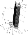
- the FIG. 1 shows an exploded view of a heat exchanger 10.
- the heat exchanger 10 is in the illustrated embodiment, a charge air cooler 10 and can be used to cool the charge air for an internal combustion engine of a motor vehicle.
- the heat exchanger 10 has in the illustrated embodiment, a first heat transfer element 12, which is constructed as an I-flow heat exchanger, and a second heat transfer element 14, which is constructed as a U-flow heat exchanger.
- the first heat transfer element 12 is preferably a high-temperature cooler and the second heat transfer element 14 is preferably a low-temperature cooler.
- the first heat transfer element 12 is part of a first coolant circuit (not shown) and the second heat transfer element is part of a second coolant circuit (not shown).
- the heat exchanger 10 may in this case be in particular a sequential, indirect intercooler (iLLK) 10.
- iLLK sequential, indirect intercooler
- the indirect intercooler may have two independent, separate coolant circuits.
- the hot charge air in one stage, is pre-cooled with warm coolant from, for example, the engine's main cooling circuit and cooled in a downstream second stage with cold coolant of a low temperature radiator.
- a known construction of a sequential indirect intercooler is the fin-tube system.
- the first coolant circuit with the heat transfer element 12 and the second coolant circuit with the second heat transfer element 14 each have a plurality of tubes 15, 19, wherein through the tubes 15 of the first coolant circuit, a first coolant and through the tubes 19 of the second coolant circuit, a second fluid can flow.
- the tubes 15 and 19 are preferably flat tubes.
- the coolant circuits are preferably independent of each other and can be operated in particular with different parameters.
- the coolant of the first coolant circuit and the coolant of the second coolant circuit may be under different pressure.
- the coolant may be a liquid or a gaseous fluid.
- the first tubes 15 of the first heat exchanger element 12 are arranged in the longitudinal direction 16 of the heat exchanger 10 in a housing, not shown.
- the tubes 15, 19 are respectively arranged on a first tube end 20 and / or on a second tube end 22 on or in a bottom 23 and are fixed by this in position.
- the first and second header boxes 24 and 28 are preferably disposed at both ends 20, 22 of the tubes 15, 19, respectively.
- a connection channel or outlet channel 26 is arranged.
- the first and second collection boxes 24 and 28 are substantially trough-shaped.
- the first header box 24 and the second header box 28 together form the cover 25.
- the second tubes 19 of the second heat exchanger element 14 are seen in the longitudinal direction 16 is arranged substantially parallel to each other and parallel to the first tubes 15 of the first heat transfer element 12.
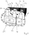
- FIG. 2 the heat exchanger 10 is shown in a perspective view in assembled state. Like parts are designated by the same reference numerals.
- the tubes 15, 19, in particular flat tubes 15, 19, are optionally arranged in a housing 18 and form the tube-fin block of a rib-tube heat exchanger.
- the cover 25 has the first collection box 24 and the second collection box 28 and closes the housing 18 at least on one of the sides 20, 22 from.
- a cover 25 is arranged on each side.
- a flange 30 is arranged at the end 20 of the tubes 15 and 19, .
- the flange 30 has at least one peripheral region projecting beyond the transverse extension direction 17 of the tubes 15 and 19.
- the flange 30 preferably has an area projecting beyond the cover 25.
- a first inlet channel 32 and a first outlet channel 34 are arranged on the flange 30. Furthermore, a second connection channel 36, which is preferably an inlet channel 36, opposite to the first connection channel 26, which is preferably an outlet channel 26, is arranged on the flange 30.
- the inlet channel 32 and the outlet channel 34 are part of the U-flow formed heat transfer element 14.
- the channel 26 and the channel 36 are part of the formed as I-flow heat transfer element 12.
- the bottom 23 is between the cover 25, the first collection box 24th and the second header box 28, and the tubes 15 and 19 are arranged.
- the embodiment of the heat exchanger 10 as a three-part heat exchanger 10 is merely an example.
- the heat exchanger 10 may also be a four-part heat exchanger having two U-flow heat transfer elements.
- FIG. 3 shows the heat exchanger 10 in a perspective view looking towards the cover 25 and that at the end 20 of the tubes 15 and 19.
- the bottom 23 includes in the region of the respective header box 24, 28, the first bottom portion 44 and the second bottom portion 46, wherein the first bottom portion 44 associated with the first collection box 24 and the second bottom portion 46 is associated with the second collection box 28.
- a connecting seam 48 is arranged between the first bottom portion 44 and the second bottom portion 46.
- the connecting seam 48 is formed by a bead 52 engages in a recess 50 and soldered.
- the first collection box 24 is in this case connected fluid-tightly directly to the bottom 23, preferably not detachably connected.
- the connection between the bottom 23 may preferably be realized by means of soldering.
- any other connection technique known per se such as gluing or welding, which is suitable for producing a fluid-tight connection, in particular from a bead 52 arranged in the recess 50. In this way, a non-positive and positive connection is established between the floor 23 and the cover 25 made.
- a plurality of first tubes 15 of the first heat exchanger element 12 are arranged on or in the first bottom section 44 and fixed on or in this.
- a plurality of second tubes 19 are disposed in the second bottom portion 46 and fixed to or in this.
- the connecting portion 48 or the connecting seam 48 has the in the collecting box 24 and / or the collecting box 28, in particular in the cover 25, introduced punched 50 and in the bottom 23rd arranged bead 52 on.
- the bead 52 may engage with the recess 50 or cutout 50, particularly in mechanical engagement.
- the punching / beading pairing can greatly simplify the assembly of the collecting box 24 at the bottom 23 by allowing a nearly automatic centering.
- the punched-out / beading connection forms the connecting seam 48, preferably the soldering seam 48.
- a partition wall 49 is arranged in the collecting box 28, which can realize a deflection of the coolant flow between coolant supply and coolant return.
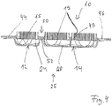
- the partition wall 49 is in the sectional view of the heat exchanger 10 of FIG. 4 shown.
- the first collection box 24 and the second collection box 28 may be formed as a one-piece component, as the cover 25.
- the first collection box 24 and the second collection box 28 may also initially be made in two parts and connected so that the cover 25 is formed.
- the cutout 50 is chosen such that the bead 52 can protrude into this.
- FIG. 5 is an illustration of a mounted and soldered heat exchanger 10 in plan view of the collection box 24 and 28, so seen in the longitudinal direction 16 frontally on the first collection box 24 and the second collection box 28.
- Recognizable is the seam 48, which is formed as a solder seam 48.
- the connecting seam 48 is preferably a peripheral connecting seam 48 or part of a peripheral connecting seam.
Landscapes
- Engineering & Computer Science (AREA)
- Physics & Mathematics (AREA)
- Thermal Sciences (AREA)
- Mechanical Engineering (AREA)
- General Engineering & Computer Science (AREA)
- Chemical & Material Sciences (AREA)
- Combustion & Propulsion (AREA)
- Heat-Exchange Devices With Radiators And Conduit Assemblies (AREA)
Claims (10)
- Echangeur de chaleur, en particulier pour un véhicule automobile, comprenant un premier circuit de liquide de refroidissement qui présente plusieurs premiers tubes (15), et comprenant un deuxième circuit de liquide de refroidissement qui présente plusieurs deuxièmes tubes (19), comprenant un fond (23), où le fond (23) présente une moulure (52), où le fond (23) présente une première zone de fond (44) comportant des ouvertures servant au logement des premiers tubes (15) et une deuxième zone de fond (46) comportant des ouvertures servant au logement des deuxièmes tubes (19), comprenant un élément de recouvrement (25) qui est assemblé avec le fond (23), caractérisé en ce que l'élément de recouvrement (25) présente un premier bac collecteur (24) et un deuxième bac collecteur (28), où le premier bac collecteur (24) est relié de manière fluidiquement étanche à la première zone de fond (44), et le deuxième bac collecteur (28) est relié de manière fluidiquement étanche à la deuxième zone de fond (46), où l'élément de recouvrement (25) présente, entre le premier et le deuxième bac collecteur (24, 28), une ouverture (50) servant au logement de la moulure (52).
- Echangeur de chaleur selon la revendication 1, caractérisé en ce que l'ouverture (50) de l'élément de recouvrement (25) est découpée par matriçage.
- Echangeur de chaleur selon l'une des revendications précédentes, caractérisé en ce que le fond (23) présente une zone périphérique.
- Echangeur de chaleur selon l'une quelconque des revendications précédentes, caractérisé en ce que l'élément de recouvrement (25) est assemblé avec le fond (23) par action de force et par complémentarité de forme.
- Echangeur de chaleur selon l'une quelconque des revendications précédentes, caractérisé en ce que l'élément de recouvrement (25) forme, avec le fond (23), un deuxième conduit d'arrivée (32) et un deuxième conduit d'évacuation (36, 26) pour le deuxième bac collecteur (28), ainsi qu'un premier conduit (26, 36) pour le premier bac collecteur (24).
- Echangeur de chaleur selon l'une quelconque des revendications précédentes, caractérisé en ce que le fond (23) présente des ouvertures pour un premier conduit d'arrivée (26, 36), pour le premier conduit d'évacuation (36, 26) et pour le conduit d'arrivée et d'évacuation (32, 34).
- Echangeur de chaleur selon l'une quelconque des revendications précédentes, caractérisé en ce que l'échangeur de chaleur (10) est un refroidisseur indirect d'air de suralimentation servant au refroidissement de l'air de suralimentation.
- Echangeur de chaleur selon l'une quelconque des revendications précédentes, caractérisé en ce qu'il est prévu un premier élément d'échangeur de chaleur (12) et un deuxième élément d'échangeur de chaleur (14) qui sont disposés de manière adjacente et parallèle l'un par rapport à l'autre.
- Echangeur de chaleur selon l'une quelconque des revendications précédentes, caractérisé en ce que le premier élément d'échangeur de chaleur (12) et le deuxième élément d'échangeur de chaleur (14) présentent respectivement des tubes, où les tubes du premier et du deuxième élément d'échangeur de chaleur sont disposés en étant parallèles les uns aux autres.
- Véhicule automobile comprenant un échangeur de chaleur (10), en particulier un refroidisseur d'air de suralimentation, selon l'une quelconque des revendications précédentes.
Applications Claiming Priority (2)
| Application Number | Priority Date | Filing Date | Title |
|---|---|---|---|
| DE102014201264.3A DE102014201264A1 (de) | 2014-01-23 | 2014-01-23 | Wärmeübertrager |
| PCT/EP2015/051364 WO2015110581A1 (fr) | 2014-01-23 | 2015-01-23 | Échangeur de chaleur |
Publications (2)
| Publication Number | Publication Date |
|---|---|
| EP3097379A1 EP3097379A1 (fr) | 2016-11-30 |
| EP3097379B1 true EP3097379B1 (fr) | 2019-04-17 |
Family
ID=52423709
Family Applications (1)
| Application Number | Title | Priority Date | Filing Date |
|---|---|---|---|
| EP15701339.2A Active EP3097379B1 (fr) | 2014-01-23 | 2015-01-23 | Échangeur de chaleur |
Country Status (4)
| Country | Link |
|---|---|
| US (1) | US20170010056A1 (fr) |
| EP (1) | EP3097379B1 (fr) |
| DE (1) | DE102014201264A1 (fr) |
| WO (1) | WO2015110581A1 (fr) |
Families Citing this family (2)
| Publication number | Priority date | Publication date | Assignee | Title |
|---|---|---|---|---|
| DE102018209775A1 (de) * | 2018-06-18 | 2019-12-19 | Mahle International Gmbh | Sammler für einen Wärmetauscher |
| FR3082884B1 (fr) * | 2018-06-26 | 2021-01-15 | Valeo Systemes Thermiques | Dispositif de ventilation pour vehicule automobile |
Citations (4)
| Publication number | Priority date | Publication date | Assignee | Title |
|---|---|---|---|---|
| JPH03260597A (ja) * | 1990-03-07 | 1991-11-20 | Nippondenso Co Ltd | 熱交換器 |
| JPH09152298A (ja) * | 1995-11-29 | 1997-06-10 | Denso Corp | 熱交換器 |
| DE19961199A1 (de) * | 1999-12-18 | 2001-06-28 | Modine Mfg Co | Luftbeaufschlagte Wärmeübertrageranordnung |
| US20080169085A1 (en) * | 2007-01-12 | 2008-07-17 | Halla Climate Control Corp. | Heat exchanger |
Family Cites Families (6)
| Publication number | Priority date | Publication date | Assignee | Title |
|---|---|---|---|---|
| JP2864170B2 (ja) * | 1991-02-13 | 1999-03-03 | 株式会社ゼクセル | 熱交換器 |
| JPH1019490A (ja) * | 1996-06-28 | 1998-01-23 | Denso Corp | 熱交換器 |
| DE69719489T2 (de) * | 1996-12-04 | 2003-12-24 | Toyo Radiator Co., Ltd. | Wärmetauscher |
| US8353330B2 (en) * | 2007-11-02 | 2013-01-15 | Halla Climate Control Corp. | Heat exchanger |
| WO2009127063A1 (fr) * | 2008-04-17 | 2009-10-22 | Dana Canada Corporation | Echangeur de chaleur à écoulement en u |
| DE102010063324A1 (de) * | 2010-12-17 | 2012-06-21 | Behr Gmbh & Co. Kg | Vorrichtung zur Kühlung von Ladeluft, System zum Konditionieren von Ladeluft und Ansaugmodul für einen Verbrennungsmotor |
-
2014
- 2014-01-23 DE DE102014201264.3A patent/DE102014201264A1/de not_active Withdrawn
-
2015
- 2015-01-23 US US15/113,483 patent/US20170010056A1/en not_active Abandoned
- 2015-01-23 WO PCT/EP2015/051364 patent/WO2015110581A1/fr not_active Ceased
- 2015-01-23 EP EP15701339.2A patent/EP3097379B1/fr active Active
Patent Citations (4)
| Publication number | Priority date | Publication date | Assignee | Title |
|---|---|---|---|---|
| JPH03260597A (ja) * | 1990-03-07 | 1991-11-20 | Nippondenso Co Ltd | 熱交換器 |
| JPH09152298A (ja) * | 1995-11-29 | 1997-06-10 | Denso Corp | 熱交換器 |
| DE19961199A1 (de) * | 1999-12-18 | 2001-06-28 | Modine Mfg Co | Luftbeaufschlagte Wärmeübertrageranordnung |
| US20080169085A1 (en) * | 2007-01-12 | 2008-07-17 | Halla Climate Control Corp. | Heat exchanger |
Also Published As
| Publication number | Publication date |
|---|---|
| EP3097379A1 (fr) | 2016-11-30 |
| WO2015110581A1 (fr) | 2015-07-30 |
| US20170010056A1 (en) | 2017-01-12 |
| DE102014201264A1 (de) | 2015-07-23 |
Similar Documents
| Publication | Publication Date | Title |
|---|---|---|
| EP2628896B1 (fr) | Dispositif de transfert de chaleur | |
| DE112017006549B4 (de) | Ladeluftkühler | |
| DE102014000450B4 (de) | Einlasskrümmer mit Ladeluftkühler | |
| EP2652285B1 (fr) | Dispositif de refroidissement de l'air suralimenté, et module de refroidissement de l`air de suralimentation | |
| DE112019003711B4 (de) | Integrierter Flüssigkeits-/Luftgekühlter Kondensator und Niedertemperatur-Kühler | |
| EP3169964B1 (fr) | Échangeur de chaleur | |
| DE112007002824T5 (de) | Zweidimensionaler Mehrfluid-Wärmetauscher | |
| EP1911946A2 (fr) | Dispositif de refroidissement de l'air de suralimentation pour un moteur à combustion interne, système doté d'un dispositif de refroidissement de l'air de suralimentation | |
| DE102007016282A1 (de) | Wärmetauscher und Verfahren | |
| DE102012105588A1 (de) | Wärmetauscher | |
| EP1586845B1 (fr) | Echangeur de chaleur pour un gas d'echappement | |
| DE112009000888T5 (de) | Kalibrierte Umgehungsstruktur für einen Wärmetauscher | |
| EP2765286A1 (fr) | Dispositif d'alimentation en air frais d'un moteur à combustion interne | |
| EP2936034A1 (fr) | Échangeur de chaleur | |
| DE112014005907T5 (de) | Konischer Wärmetauscher | |
| EP2972011A1 (fr) | Échangeur de chaleur | |
| EP1956212A1 (fr) | Agencement d'un refroidisseur d'air de suralimentation dans un système d'aspiration d'un moteur à combustion interne | |
| DE102011076172A1 (de) | Lamellenwärmeübertrager | |
| DE102014119227A1 (de) | Abgaswärmeübertrager | |
| EP3097379B1 (fr) | Échangeur de chaleur | |
| EP2481899A1 (fr) | Echangeur thermique | |
| DE202019101397U1 (de) | Abgaskühler | |
| EP3247960B1 (fr) | Échangeur de chaleur à plaques empilées | |
| DE102010025030B4 (de) | Wärmetauscher für einen Verbrennungsmotor | |
| DE102021208924A1 (de) | Wärmeübertrager |
Legal Events
| Date | Code | Title | Description |
|---|---|---|---|
| PUAI | Public reference made under article 153(3) epc to a published international application that has entered the european phase |
Free format text: ORIGINAL CODE: 0009012 |
|
| 17P | Request for examination filed |
Effective date: 20160823 |
|
| AK | Designated contracting states |
Kind code of ref document: A1 Designated state(s): AL AT BE BG CH CY CZ DE DK EE ES FI FR GB GR HR HU IE IS IT LI LT LU LV MC MK MT NL NO PL PT RO RS SE SI SK SM TR |
|
| AX | Request for extension of the european patent |
Extension state: BA ME |
|
| DAX | Request for extension of the european patent (deleted) | ||
| STAA | Information on the status of an ep patent application or granted ep patent |
Free format text: STATUS: EXAMINATION IS IN PROGRESS |
|
| 17Q | First examination report despatched |
Effective date: 20180205 |
|
| GRAP | Despatch of communication of intention to grant a patent |
Free format text: ORIGINAL CODE: EPIDOSNIGR1 |
|
| STAA | Information on the status of an ep patent application or granted ep patent |
Free format text: STATUS: GRANT OF PATENT IS INTENDED |
|
| INTG | Intention to grant announced |
Effective date: 20181102 |
|
| GRAJ | Information related to disapproval of communication of intention to grant by the applicant or resumption of examination proceedings by the epo deleted |
Free format text: ORIGINAL CODE: EPIDOSDIGR1 |
|
| STAA | Information on the status of an ep patent application or granted ep patent |
Free format text: STATUS: EXAMINATION IS IN PROGRESS |
|
| GRAR | Information related to intention to grant a patent recorded |
Free format text: ORIGINAL CODE: EPIDOSNIGR71 |
|
| GRAS | Grant fee paid |
Free format text: ORIGINAL CODE: EPIDOSNIGR3 |
|
| STAA | Information on the status of an ep patent application or granted ep patent |
Free format text: STATUS: GRANT OF PATENT IS INTENDED |
|
| GRAA | (expected) grant |
Free format text: ORIGINAL CODE: 0009210 |
|
| STAA | Information on the status of an ep patent application or granted ep patent |
Free format text: STATUS: THE PATENT HAS BEEN GRANTED |
|
| INTC | Intention to grant announced (deleted) | ||
| INTG | Intention to grant announced |
Effective date: 20190306 |
|
| AK | Designated contracting states |
Kind code of ref document: B1 Designated state(s): AL AT BE BG CH CY CZ DE DK EE ES FI FR GB GR HR HU IE IS IT LI LT LU LV MC MK MT NL NO PL PT RO RS SE SI SK SM TR |
|
| REG | Reference to a national code |
Ref country code: GB Ref legal event code: FG4D Free format text: NOT ENGLISH |
|
| REG | Reference to a national code |
Ref country code: CH Ref legal event code: EP |
|
| REG | Reference to a national code |
Ref country code: DE Ref legal event code: R096 Ref document number: 502015008722 Country of ref document: DE |
|
| REG | Reference to a national code |
Ref country code: AT Ref legal event code: REF Ref document number: 1122019 Country of ref document: AT Kind code of ref document: T Effective date: 20190515 Ref country code: IE Ref legal event code: FG4D Free format text: LANGUAGE OF EP DOCUMENT: GERMAN |
|
| REG | Reference to a national code |
Ref country code: NL Ref legal event code: MP Effective date: 20190417 |
|
| REG | Reference to a national code |
Ref country code: LT Ref legal event code: MG4D |
|
| PG25 | Lapsed in a contracting state [announced via postgrant information from national office to epo] |
Ref country code: NL Free format text: LAPSE BECAUSE OF FAILURE TO SUBMIT A TRANSLATION OF THE DESCRIPTION OR TO PAY THE FEE WITHIN THE PRESCRIBED TIME-LIMIT Effective date: 20190417 |
|
| PG25 | Lapsed in a contracting state [announced via postgrant information from national office to epo] |
Ref country code: NO Free format text: LAPSE BECAUSE OF FAILURE TO SUBMIT A TRANSLATION OF THE DESCRIPTION OR TO PAY THE FEE WITHIN THE PRESCRIBED TIME-LIMIT Effective date: 20190717 Ref country code: AL Free format text: LAPSE BECAUSE OF FAILURE TO SUBMIT A TRANSLATION OF THE DESCRIPTION OR TO PAY THE FEE WITHIN THE PRESCRIBED TIME-LIMIT Effective date: 20190417 Ref country code: FI Free format text: LAPSE BECAUSE OF FAILURE TO SUBMIT A TRANSLATION OF THE DESCRIPTION OR TO PAY THE FEE WITHIN THE PRESCRIBED TIME-LIMIT Effective date: 20190417 Ref country code: HR Free format text: LAPSE BECAUSE OF FAILURE TO SUBMIT A TRANSLATION OF THE DESCRIPTION OR TO PAY THE FEE WITHIN THE PRESCRIBED TIME-LIMIT Effective date: 20190417 Ref country code: SE Free format text: LAPSE BECAUSE OF FAILURE TO SUBMIT A TRANSLATION OF THE DESCRIPTION OR TO PAY THE FEE WITHIN THE PRESCRIBED TIME-LIMIT Effective date: 20190417 Ref country code: PT Free format text: LAPSE BECAUSE OF FAILURE TO SUBMIT A TRANSLATION OF THE DESCRIPTION OR TO PAY THE FEE WITHIN THE PRESCRIBED TIME-LIMIT Effective date: 20190817 Ref country code: LT Free format text: LAPSE BECAUSE OF FAILURE TO SUBMIT A TRANSLATION OF THE DESCRIPTION OR TO PAY THE FEE WITHIN THE PRESCRIBED TIME-LIMIT Effective date: 20190417 Ref country code: ES Free format text: LAPSE BECAUSE OF FAILURE TO SUBMIT A TRANSLATION OF THE DESCRIPTION OR TO PAY THE FEE WITHIN THE PRESCRIBED TIME-LIMIT Effective date: 20190417 |
|
| PG25 | Lapsed in a contracting state [announced via postgrant information from national office to epo] |
Ref country code: GR Free format text: LAPSE BECAUSE OF FAILURE TO SUBMIT A TRANSLATION OF THE DESCRIPTION OR TO PAY THE FEE WITHIN THE PRESCRIBED TIME-LIMIT Effective date: 20190718 Ref country code: PL Free format text: LAPSE BECAUSE OF FAILURE TO SUBMIT A TRANSLATION OF THE DESCRIPTION OR TO PAY THE FEE WITHIN THE PRESCRIBED TIME-LIMIT Effective date: 20190417 Ref country code: BG Free format text: LAPSE BECAUSE OF FAILURE TO SUBMIT A TRANSLATION OF THE DESCRIPTION OR TO PAY THE FEE WITHIN THE PRESCRIBED TIME-LIMIT Effective date: 20190717 Ref country code: RS Free format text: LAPSE BECAUSE OF FAILURE TO SUBMIT A TRANSLATION OF THE DESCRIPTION OR TO PAY THE FEE WITHIN THE PRESCRIBED TIME-LIMIT Effective date: 20190417 Ref country code: LV Free format text: LAPSE BECAUSE OF FAILURE TO SUBMIT A TRANSLATION OF THE DESCRIPTION OR TO PAY THE FEE WITHIN THE PRESCRIBED TIME-LIMIT Effective date: 20190417 |
|
| PG25 | Lapsed in a contracting state [announced via postgrant information from national office to epo] |
Ref country code: IS Free format text: LAPSE BECAUSE OF FAILURE TO SUBMIT A TRANSLATION OF THE DESCRIPTION OR TO PAY THE FEE WITHIN THE PRESCRIBED TIME-LIMIT Effective date: 20190817 |
|
| REG | Reference to a national code |
Ref country code: DE Ref legal event code: R097 Ref document number: 502015008722 Country of ref document: DE |
|
| PG25 | Lapsed in a contracting state [announced via postgrant information from national office to epo] |
Ref country code: CZ Free format text: LAPSE BECAUSE OF FAILURE TO SUBMIT A TRANSLATION OF THE DESCRIPTION OR TO PAY THE FEE WITHIN THE PRESCRIBED TIME-LIMIT Effective date: 20190417 Ref country code: RO Free format text: LAPSE BECAUSE OF FAILURE TO SUBMIT A TRANSLATION OF THE DESCRIPTION OR TO PAY THE FEE WITHIN THE PRESCRIBED TIME-LIMIT Effective date: 20190417 Ref country code: EE Free format text: LAPSE BECAUSE OF FAILURE TO SUBMIT A TRANSLATION OF THE DESCRIPTION OR TO PAY THE FEE WITHIN THE PRESCRIBED TIME-LIMIT Effective date: 20190417 Ref country code: DK Free format text: LAPSE BECAUSE OF FAILURE TO SUBMIT A TRANSLATION OF THE DESCRIPTION OR TO PAY THE FEE WITHIN THE PRESCRIBED TIME-LIMIT Effective date: 20190417 Ref country code: SK Free format text: LAPSE BECAUSE OF FAILURE TO SUBMIT A TRANSLATION OF THE DESCRIPTION OR TO PAY THE FEE WITHIN THE PRESCRIBED TIME-LIMIT Effective date: 20190417 |
|
| PLBE | No opposition filed within time limit |
Free format text: ORIGINAL CODE: 0009261 |
|
| STAA | Information on the status of an ep patent application or granted ep patent |
Free format text: STATUS: NO OPPOSITION FILED WITHIN TIME LIMIT |
|
| PG25 | Lapsed in a contracting state [announced via postgrant information from national office to epo] |
Ref country code: SM Free format text: LAPSE BECAUSE OF FAILURE TO SUBMIT A TRANSLATION OF THE DESCRIPTION OR TO PAY THE FEE WITHIN THE PRESCRIBED TIME-LIMIT Effective date: 20190417 Ref country code: IT Free format text: LAPSE BECAUSE OF FAILURE TO SUBMIT A TRANSLATION OF THE DESCRIPTION OR TO PAY THE FEE WITHIN THE PRESCRIBED TIME-LIMIT Effective date: 20190417 |
|
| 26N | No opposition filed |
Effective date: 20200120 |
|
| PG25 | Lapsed in a contracting state [announced via postgrant information from national office to epo] |
Ref country code: TR Free format text: LAPSE BECAUSE OF FAILURE TO SUBMIT A TRANSLATION OF THE DESCRIPTION OR TO PAY THE FEE WITHIN THE PRESCRIBED TIME-LIMIT Effective date: 20190417 |
|
| PG25 | Lapsed in a contracting state [announced via postgrant information from national office to epo] |
Ref country code: SI Free format text: LAPSE BECAUSE OF FAILURE TO SUBMIT A TRANSLATION OF THE DESCRIPTION OR TO PAY THE FEE WITHIN THE PRESCRIBED TIME-LIMIT Effective date: 20190417 |
|
| REG | Reference to a national code |
Ref country code: DE Ref legal event code: R119 Ref document number: 502015008722 Country of ref document: DE |
|
| PG25 | Lapsed in a contracting state [announced via postgrant information from national office to epo] |
Ref country code: MC Free format text: LAPSE BECAUSE OF FAILURE TO SUBMIT A TRANSLATION OF THE DESCRIPTION OR TO PAY THE FEE WITHIN THE PRESCRIBED TIME-LIMIT Effective date: 20190417 |
|
| REG | Reference to a national code |
Ref country code: CH Ref legal event code: PL |
|
| GBPC | Gb: european patent ceased through non-payment of renewal fee |
Effective date: 20200123 |
|
| REG | Reference to a national code |
Ref country code: BE Ref legal event code: MM Effective date: 20200131 |
|
| PG25 | Lapsed in a contracting state [announced via postgrant information from national office to epo] |
Ref country code: FR Free format text: LAPSE BECAUSE OF NON-PAYMENT OF DUE FEES Effective date: 20200131 Ref country code: LU Free format text: LAPSE BECAUSE OF NON-PAYMENT OF DUE FEES Effective date: 20200123 Ref country code: DE Free format text: LAPSE BECAUSE OF NON-PAYMENT OF DUE FEES Effective date: 20200801 Ref country code: GB Free format text: LAPSE BECAUSE OF NON-PAYMENT OF DUE FEES Effective date: 20200123 |
|
| PG25 | Lapsed in a contracting state [announced via postgrant information from national office to epo] |
Ref country code: LI Free format text: LAPSE BECAUSE OF NON-PAYMENT OF DUE FEES Effective date: 20200131 Ref country code: CH Free format text: LAPSE BECAUSE OF NON-PAYMENT OF DUE FEES Effective date: 20200131 Ref country code: BE Free format text: LAPSE BECAUSE OF NON-PAYMENT OF DUE FEES Effective date: 20200131 |
|
| PG25 | Lapsed in a contracting state [announced via postgrant information from national office to epo] |
Ref country code: IE Free format text: LAPSE BECAUSE OF NON-PAYMENT OF DUE FEES Effective date: 20200123 |
|
| REG | Reference to a national code |
Ref country code: AT Ref legal event code: MM01 Ref document number: 1122019 Country of ref document: AT Kind code of ref document: T Effective date: 20200123 |
|
| PG25 | Lapsed in a contracting state [announced via postgrant information from national office to epo] |
Ref country code: AT Free format text: LAPSE BECAUSE OF NON-PAYMENT OF DUE FEES Effective date: 20200123 |
|
| PG25 | Lapsed in a contracting state [announced via postgrant information from national office to epo] |
Ref country code: MT Free format text: LAPSE BECAUSE OF FAILURE TO SUBMIT A TRANSLATION OF THE DESCRIPTION OR TO PAY THE FEE WITHIN THE PRESCRIBED TIME-LIMIT Effective date: 20190417 Ref country code: CY Free format text: LAPSE BECAUSE OF FAILURE TO SUBMIT A TRANSLATION OF THE DESCRIPTION OR TO PAY THE FEE WITHIN THE PRESCRIBED TIME-LIMIT Effective date: 20190417 |
|
| PG25 | Lapsed in a contracting state [announced via postgrant information from national office to epo] |
Ref country code: MK Free format text: LAPSE BECAUSE OF FAILURE TO SUBMIT A TRANSLATION OF THE DESCRIPTION OR TO PAY THE FEE WITHIN THE PRESCRIBED TIME-LIMIT Effective date: 20190417 |