EP3097575B1 - Kühlvorrichtung für eine gasisolierte schaltanlage - Google Patents
Kühlvorrichtung für eine gasisolierte schaltanlage Download PDFInfo
- Publication number
- EP3097575B1 EP3097575B1 EP14880084.0A EP14880084A EP3097575B1 EP 3097575 B1 EP3097575 B1 EP 3097575B1 EP 14880084 A EP14880084 A EP 14880084A EP 3097575 B1 EP3097575 B1 EP 3097575B1
- Authority
- EP
- European Patent Office
- Prior art keywords
- fluid conduit
- gas chamber
- cooling device
- condenser
- evaporation part
- Prior art date
- Legal status (The legal status is an assumption and is not a legal conclusion. Google has not performed a legal analysis and makes no representation as to the accuracy of the status listed.)
- Active
Links
Images


Classifications
-
- H—ELECTRICITY
- H01—ELECTRIC ELEMENTS
- H01H—ELECTRIC SWITCHES; RELAYS; SELECTORS; EMERGENCY PROTECTIVE DEVICES
- H01H9/00—Details of switching devices, not covered by groups H01H1/00 - H01H7/00
- H01H9/52—Cooling of switch parts
-
- H—ELECTRICITY
- H02—GENERATION; CONVERSION OR DISTRIBUTION OF ELECTRIC POWER
- H02B—BOARDS, SUBSTATIONS OR SWITCHING ARRANGEMENTS FOR THE SUPPLY OR DISTRIBUTION OF ELECTRIC POWER
- H02B1/00—Frameworks, boards, panels, desks, casings; Details of substations or switching arrangements
- H02B1/56—Cooling; Ventilation
- H02B1/565—Cooling; Ventilation for cabinets
-
- H—ELECTRICITY
- H01—ELECTRIC ELEMENTS
- H01H—ELECTRIC SWITCHES; RELAYS; SELECTORS; EMERGENCY PROTECTIVE DEVICES
- H01H9/00—Details of switching devices, not covered by groups H01H1/00 - H01H7/00
- H01H9/52—Cooling of switch parts
- H01H2009/523—Cooling of switch parts by using heat pipes
-
- H—ELECTRICITY
- H01—ELECTRIC ELEMENTS
- H01H—ELECTRIC SWITCHES; RELAYS; SELECTORS; EMERGENCY PROTECTIVE DEVICES
- H01H9/00—Details of switching devices, not covered by groups H01H1/00 - H01H7/00
- H01H9/52—Cooling of switch parts
- H01H2009/526—Cooling of switch parts of the high voltage switches
Definitions
- This invention relates to the field of power products, and more particularly to a Gas Insulated Switchgear device cooling technology field.
- Heat dissipation is a well-known bottleneck in high rated current switchgears. As the gas insulated switchgears are all completely sealed, the temperature rise in the switchgear is very serious. The heat can only be dissipated via the air outside of the gas chamber. During long time operation under heavy current load, the heat accumulates gradually and makes the gas chamber internal temperature rise rapidly.
- the current solution such as to solve 2500A temperature rise in gas insulated product
- the temperature rise value of the most critical point is rather close to the limitation.
- another considering point is the service life of the fan and reliability, since gas insulated switchgear is maintenance free product.
- EP 1 737 009 A1 discloses an electrical device with a conductor which is arranged in a housing.
- An evaporator is arranged on the conductor and connected to a condenser, which is placed at the outside of the housing, via a heat pipe.
- JP H03 30400 A describes a cooling device for a gas insulation cubicle.
- the cooling device for a Gas Insulated Switchgear comprises a condenser arranged outside a gas chamber and an evaporation part arranged in the gas chamber, a gas filling the gas chamber, and at least one fluid conduit connecting the evaporation part and the condenser.
- the fluid conduit is heat conductive and is filled with liquid to transfer heat from the evaporation part to the condenser, and wherein the evaporation part is in contact with the gas filling the gas chamber on all sides.
- WO 2011 / 051200 A1 discloses a device for cooling a medium voltage apparatus using heat pipes.
- a switchgear is placed within a sheath, which is in direct contact with evaporators of the heat pipes.
- the heat pipes further connect to condensers outside of a casing housing the switchgear.
- the present invention provides a cooling device used for a Gas Insulated Switchgear.
- the cooling device comprises a condenser arranged outside the gas chamber, an evaporation part arranged in the gas chamber, and at least one fluid conduit connect the evaporator device and the condenser; the fluid conduit is heat conductive and is filled with liquid, especially a kind of low-boiling condensate, to transfer heat from the evaporation part to the condenser and hot evaporation can condense to liquid then flow back to the conduit for next cooling cycle.
- the evaporation part and the at least one fluid conduit are integrated together, and the evaporation part is the gas chamber end of the at least one fluid conduit.
- the fluid conduit can be only one fluid pipe or a plurality of fluid pipes.
- the condenser comprises a heat sink which is connected with the fluid conduit and is arranged outside of the gas chamber.
- the condenser is a separated part and it is liquid connective with all the fluid conduits.
- the low-boiling condensate can flow among the fluid conduits and the condenser.
- the exterior outline of the fluid conduit can be round, square, elliptical, with sheds or any other shapes.
- the cross section of the fluid conduit can be round, annular, or a shape of the external outline different with the internal outline.
- a fluid conduit is easy to get and the heat dissipation efficiency is high enough, it is easy to implement the solution according to the present invention to a Gas Insulated Switchgear.
- the condenser is arranged on the top of the gas chamber or at the back of the gas chamber.
- the fluid conduit may comprise an angle and is adapted to connect the condenser with the evaporation part.
- the condenser end of the fluid conduit is open.
- the present invention provides a cooling device 1 used for a Gas Insulated Switchgear which is filled with gas such as SF6 in the gas chamber 2.
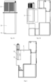
- Fig. 1A shows the structure of the cooling device 1 according to the present invention.
- Fig. 1B shows the switchgear equipped with a cooling device 1.
- the cooling device 1 comprises a condenser 11 arranged outside the gas chamber 2, an evaporation part 13 arranged in the gas chamber, and at least one fluid conduit 12 connect the evaporator device 13 and the condenser 11.
- the fluid conduit 11 is heat conductive and is filled with liquid 120, especially a kind of low-boiling condensate, to transfer heat from the evaporation part 13 to the condenser 11.
- the evaporation part 13 and the at least one fluid conduit 12 is integrated together, and the evaporation part 13 is the gas chamber end of the at least one fluid conduit 12.
- the fluid conduit 12 has two ends.
- the gas chamber end of the at least one fluid conduit 12 means the end of the fluid conduit 12 which is located at the gas chamber side, and the condenser end of the fluid conduit means the end of the fluid conduit 12 which is located at the condenser side.
- the condenser 11 comprising a plurality of heat sinks 110 which is arranged around of the fluid conduit 12 outside of the gas chamber 2. Or the heat sink provides an opening which is adapted to close connect with the top opening of the fluid conduit 12.
- the fluid conduit 12 is made of high thermal conductive materials, such as copper and aluminium
- the low-boiling condensate 120 in the fluid conduit 12 flow to the evaporation part 13 which is the bottom of the fluid conduit 12 when the temperature of the gas chamber 2 is not high.
- the low-boiling condensate 120 in the evaporation part 13 is heated and evaporated gradually.
- the high temperature evaporated condensate rise to the heat sink 11 through the fluid conduit 12.
- the evaporated condensate will be cooled down by the heat sink 11 through heat transfer from the condensate to the heat sink, and then from the heat sink to the air.
- the evaporated condensate will be condensed to liquid, and then flows to the evaporation part 13 again.
- the temperature of the gas chamber 2 is cooled down.
- the evaporation part 13 and the at least one fluid conduit 12 are integrated together. That means the gas chamber end of the fluid conduit 12 functions both as fluid conduit and the evaporation part.
- This structure is simple and compact, and it also saves cost.
- Fig. 2 is the section view of the switchgear equipped with a cooling device .
- the length L12 of the fluid conduit 12 can be varied.
- Fig. 3A-3B shows the structure of the cooling device 1.
- the fluid conduit 12 comprises a plurality of fluid pipes 12' which are separated with each other.
- the evaporation part 13' is a separate structure with the fluid pipes 12'.
- the bottom end of the plurality of fluid pipes 12' are liquid connective with each other and liquid connective with the evaporation part 13'.
- the low-boiling condensate 120 in the fluid pipes 12' flow to the evaporation part 13' when the temperature of the gas chamber 2 is not high.
- the low-boiling condensate 120 in the evaporation part 13' is heated and evaporated gradually.
- the high temperature evaporated condensate rise to the heat sink 11 through the fluid pipes 12'.
- the evaporated condensate will be cooled down by the heat sink 11 through heat transfer between the evaporated condensate and the air, and will be condensed to liquid. Then, the condensate flows to the evaporation part 13' again via the fluid pipes 12'.
- the exterior outline of the fluid conduit can be many shapes as shown in Fig. 4A-4C.
- Fig. 4A shows the exterior outline of the fluid conduit 12 is square 1211;
- Fig. 4B shows the exterior outline of the fluid conduit is round 1212; and
- Fig. 4C shows the exterior outline of the fluid conduit is with sheds 1213.
- exterior outline of the fluid conduit 12 can be varied from many other shapes such as elliptical which are not shown here.
- the exterior outline of the fluid conduit with sheds 1213 can increase the contact of the fluid conduit 12 with gas filled in the gas chamber such as SF6. Then, the heat transfer and heat dissipation efficiency is highly increased. Furthermore, the internal space of the fluid conduit 12 decreased and less the low-boiling condensate 120 needed. Thus the cost is saved.
- the fluid conduit according to the invention is designed to comprise a hollow part to increase the contact of the fluid conduit 12 with the SF6 in the gas chamber and thus to increase the heat transfer and heat dissipation efficiency as shown in Fig. 5 .
- Fig. 6 is the section view in A-A direction of Fig. 5 .
- the cross section of fluid conduit 12 can be round, square ring 1221 as shown in Fig. 6A , or a shape of the external outline different with the internal outline 1222, 1223 as shown in Fig. 6B and Fig. 6C , or any other shapes.
- the fluid conduit 12 can be located anywhere in the gas chamber 2. The preferred location is in not close to a gas chamber wall, thus to increase the contact with the SF6 in the gas chamber.
- Fig. 7A-7B shows the cooling device of an embodiment of the present invention, wherein a heat conduit 123 is used.
- a heat conduit or heat pipe is a heattransfer device that combines the principles of both thermal conductivity and phase transition to efficiently manage the transfer of heat between two solid interfaces.
- a liquid in contact with a thermally conductive solid surface turns into a vapor by absorbing heat from that surface.
- the vapor then travels along the heat conduit to the cold interface and condenses back into a liquid - releasing the latent heat.
- the liquid then returns to the hot interface through either capillary action, centrifugal force, or gravity, and the cycle repeats.
- Heat conduits are thermal superconductors, due to the very high heat transfer coefficients for boiling and condensation.
- the effective thermal conductivity varies with heat conduit length, and can approach 100,000 W/m K for long heat conduits, in comparison with approximately 400 W/m K for copper.
- the heat conduit 123 functions both as fluid conduit and the evaporation part.
- the condenser 11 comprising a plurality of heat sinks 110 which is arranged around of the fluid conduit 123 outside of the gas chamber 2. As shown in Fig. 7A , the condenser 11 is arranged on the top of the gas chamber 2. Or as shown in Fig. 7B , the condenser 11 is arranged at the back of the gas chamber 2, wherein the heat conduit 123 comprising an angle 1230 and is adapted to connect the condenser with the evaporation part 13.
- the condenser 11 can also be arranged at the side of the gas chamber 2.
- the cooling device of the present invention is simple and high efficiency in heat transfer and heat dissipation.
- the Gas Insulated Switchgear does not need to do much modification.
- the cooling device of the present invention is also high reliable and low cost.
Landscapes
- Engineering & Computer Science (AREA)
- Power Engineering (AREA)
- Cooling Or The Like Of Electrical Apparatus (AREA)
Claims (10)
- Kühlvorrichtung (1) für eine gasisolierte Schaltanlage, umfassend einen Kondensator (11), der außerhalb einer Gaskammer (2) angeordnet ist, ferner umfassend einen Verdampfungsteil (13), der in der Gaskammer angeordnet ist, ein Gas, das die Gaskammer (2) füllt, und mindestens eine Fluidleitung (12), die den Verdampfungsteil (13) und den Kondensator (11) verbindet; wobei die Fluidleitung (12) wärmeleitend ist und mit Fluid (120) gefüllt ist, um Wärme von dem Verdampfungsteil (13) zu dem Kondensator (11) zu übertragen, und wobei der Verdampfungsteil (13) auf allen Seiten mit dem die Gaskammer (2) füllenden Gas in Kontakt ist, wobei die Fluidleitung (12) einen hohlen Teil an dem Gaskammerende aufweist, um den Kontakt der Fluidleitung (12) mit dem Gas in der Gaskammer (2) zu erhöhen; und wobei der Verdampfungsteil (13) und die mindestens eine Fluidleitung (12) zusammen integriert sind, und der Verdampfungsteil (13) das Gaskammerende der mindestens einen Fluidleitung (12) ist.
- Kühlvorrichtung nach Anspruch 1, wobei der Kondensator (11) eine Wärmesenke (110) umfasst, die mit der Fluidleitung (12) verbunden ist und außerhalb des Gasraums (2) angeordnet ist.
- Kühlvorrichtung nach Anspruch 1, wobei das in die Fluidleitung eingefüllte Fluid (120) niedrig siedendes Kondensat ist.
- Kühlvorrichtung nach einem der Ansprüche 1 bis 3, wobei der Kondensator (11) ein separates Teil ist und mit allen Fluidleitungen (12) fluidverbunden ist.
- Kühlvorrichtung nach einem der Ansprüche 1 bis 3, wobei der äußere Umriss der Fluidleitung (12) rund (1211), quadratisch (1212), elliptisch oder mit Rillen (1213) ist.
- Kühlvorrichtung nach einem der Ansprüche 1 bis 3, wobei der Querschnitt der Fluidleitung rund, ringförmig, quadratisch (1221), oder eine andere Form des äußeren Umrisses als die des inneren Umrisses (1222, 1223) ist.
- Kühlvorrichtung nach einem der Ansprüche 1 bis 3, wobei die Fluidleitung (12) ein Wärmerohr (123) ist, das einen Winkel (1230) aufweist und geeignet ist, den Kondensator mit dem Verdampfungsteil (13) zu verbinden.
- Kühlvorrichtung nach einem der Ansprüche 1-3, wobei der Kondensator (11) an der Oberseite des Gasraums (2) oder an der Rückseite des Gasraums (2) angeordnet ist.
- Kühlvorrichtung nach einem der Ansprüche 1 bis 3, wobei das Kondensatorende der Fluidleitung (12) offen ist.
- Kühlvorrichtung nach einem der Ansprüche 1 bis 3, wobei die Fluidleitung (12) aus wärmeleitenden Materialien besteht.
Applications Claiming Priority (1)
| Application Number | Priority Date | Filing Date | Title |
|---|---|---|---|
| PCT/CN2014/071308 WO2015109508A1 (en) | 2014-01-24 | 2014-01-24 | Cooling device for a gas insulated switchgear |
Publications (3)
| Publication Number | Publication Date |
|---|---|
| EP3097575A1 EP3097575A1 (de) | 2016-11-30 |
| EP3097575A4 EP3097575A4 (de) | 2017-08-30 |
| EP3097575B1 true EP3097575B1 (de) | 2023-03-01 |
Family
ID=53680618
Family Applications (1)
| Application Number | Title | Priority Date | Filing Date |
|---|---|---|---|
| EP14880084.0A Active EP3097575B1 (de) | 2014-01-24 | 2014-01-24 | Kühlvorrichtung für eine gasisolierte schaltanlage |
Country Status (3)
| Country | Link |
|---|---|
| EP (1) | EP3097575B1 (de) |
| CN (1) | CN106415762B (de) |
| WO (1) | WO2015109508A1 (de) |
Families Citing this family (1)
| Publication number | Priority date | Publication date | Assignee | Title |
|---|---|---|---|---|
| CN114556726B (zh) * | 2020-03-17 | 2024-07-09 | Abb瑞士股份有限公司 | 开关设备组件和开关设备 |
Family Cites Families (10)
| Publication number | Priority date | Publication date | Assignee | Title |
|---|---|---|---|---|
| GB1390908A (en) * | 1971-01-30 | 1975-04-16 | Reyrolle Parsons Ltd | Electrical switchgear |
| JPH0330400A (ja) * | 1989-06-27 | 1991-02-08 | Toshiba Corp | ガス絶縁キュービクルの冷却装置 |
| EP1672655A1 (de) * | 2004-12-20 | 2006-06-21 | Abb Research Ltd. | Vakuumschalter mit grosser Stromtragfähigkeit |
| EP1737009A1 (de) * | 2005-06-23 | 2006-12-27 | Abb Research Ltd. | Elektrische Anlage mit einem Kühlelement und Verfahren zum Betrieb dieser Anlage |
| FR2951856A1 (fr) * | 2009-10-26 | 2011-04-29 | Areva T & D Sas | Procede et dispositif de refroidissement d'une installation electrique moyenne tension sous gaine |
| FR2951857B1 (fr) * | 2009-10-26 | 2011-12-23 | Areva T & D Sas | Dispositif de refroidissement d'un appareil moyenne tension utilisant des caloducs sous tension |
| EP2426801A1 (de) * | 2010-09-02 | 2012-03-07 | ABB Research Ltd. | Sammelschiene, Verfahren zur Kühlung davon und elektrische Vorrichtung |
| DE102011075990B4 (de) * | 2011-05-17 | 2014-10-09 | Schneider Electric Sachsenwerk Gmbh | Schaltanlage für Hoch- oder Mittelspannung |
| US8695358B2 (en) * | 2011-05-23 | 2014-04-15 | Abb Research Ltd. | Switchgear having evaporative cooling apparatus |
| EP2828872B1 (de) * | 2012-03-22 | 2018-05-16 | ABB Schweiz AG | Kühlvorrichtung für eine schaltvorrichtung mit wärmerohrstruktur mit integriertem sammelschienenrohr |
-
2014
- 2014-01-24 WO PCT/CN2014/071308 patent/WO2015109508A1/en not_active Ceased
- 2014-01-24 CN CN201480073831.XA patent/CN106415762B/zh not_active Expired - Fee Related
- 2014-01-24 EP EP14880084.0A patent/EP3097575B1/de active Active
Also Published As
| Publication number | Publication date |
|---|---|
| EP3097575A1 (de) | 2016-11-30 |
| CN106415762A (zh) | 2017-02-15 |
| WO2015109508A1 (en) | 2015-07-30 |
| EP3097575A4 (de) | 2017-08-30 |
| CN106415762B (zh) | 2019-06-21 |
Similar Documents
| Publication | Publication Date | Title |
|---|---|---|
| US4005297A (en) | Vacuum-type circuit interrupters having heat-dissipating devices associated with the contact structures thereof | |
| US3852805A (en) | Heat-pipe cooled power semiconductor device assembly having integral semiconductor device evaporating surface unit | |
| EP2709220B1 (de) | Entnehmbare Schaltanlage mit wärmerohrgekühlten Thermosiphonbuchsen | |
| CN105706540B (zh) | 用于电气或电子设备的冷却装置以及包括这样的冷却装置的电气或电子设备尤其是断路器 | |
| JP2013508669A (ja) | 絶縁されたヒートパイプを利用することによって中電圧装置を冷却するための冷却装置 | |
| CN101656406B (zh) | 带冷却的高压开关 | |
| CN102687220A (zh) | 用于冷却加护套的中压电气设备的方法和装置 | |
| EP2552182A1 (de) | Doppelkreislauf-Thermosiphon zum Kühlen elektrischer und elektronischer Bauteile | |
| CN101133471A (zh) | 带热管的开关装置 | |
| CN101958200B (zh) | 带有热平衡器具的开关装置 | |
| JP2013508907A (ja) | 組み込まれたヒートパイプによって中電圧電気設備を冷却する方法、ならびにこの方法を用いたシステム | |
| EP3584897B1 (de) | Leistungsschalter | |
| EP2983261A1 (de) | Stromschiene mit integrierter Wärmerohr | |
| WO2009120589A1 (en) | Cooling fins for a heat pipe | |
| WO2015109508A1 (en) | Cooling device for a gas insulated switchgear | |
| US11573053B2 (en) | Cyclone cooler device | |
| JP2003194491A (ja) | 電気流体力学的誘導ポンピング熱エネルギー伝達システム用の電極設計 | |
| EP4151943A1 (de) | Kühlvorrichtung für eine mittelspannungs- oder hochspannungsschaltanlage | |
| EP3396288A1 (de) | Kühlvorrichtung für einen leistungswandler | |
| WO2016116204A1 (en) | Thermosyphon cooler for an electric device with inductance | |
| WO2014177553A1 (en) | Pole-piece for a power semiconductor device | |
| EP4290547B1 (de) | Kühlkörper mit dielektrischer abschirmung | |
| EP2801781B1 (de) | Kühlsystem | |
| CN110662398B (zh) | 低熔点金属相变热传导器件 | |
| KR101455785B1 (ko) | 스위칭 소자 냉각 시스템 |
Legal Events
| Date | Code | Title | Description |
|---|---|---|---|
| PUAI | Public reference made under article 153(3) epc to a published international application that has entered the european phase |
Free format text: ORIGINAL CODE: 0009012 |
|
| 17P | Request for examination filed |
Effective date: 20160530 |
|
| AK | Designated contracting states |
Kind code of ref document: A1 Designated state(s): AL AT BE BG CH CY CZ DE DK EE ES FI FR GB GR HR HU IE IS IT LI LT LU LV MC MK MT NL NO PL PT RO RS SE SI SK SM TR |
|
| AX | Request for extension of the european patent |
Extension state: BA ME |
|
| DAX | Request for extension of the european patent (deleted) | ||
| A4 | Supplementary search report drawn up and despatched |
Effective date: 20170802 |
|
| RIC1 | Information provided on ipc code assigned before grant |
Ipc: H02B 1/56 20060101ALI20170727BHEP Ipc: H05K 7/20 20060101ALI20170727BHEP Ipc: H01H 33/64 20060101ALI20170727BHEP Ipc: H01H 9/52 20060101AFI20170727BHEP Ipc: H02G 5/10 20060101ALI20170727BHEP |
|
| STAA | Information on the status of an ep patent application or granted ep patent |
Free format text: STATUS: EXAMINATION IS IN PROGRESS |
|
| 17Q | First examination report despatched |
Effective date: 20180903 |
|
| GRAP | Despatch of communication of intention to grant a patent |
Free format text: ORIGINAL CODE: EPIDOSNIGR1 |
|
| STAA | Information on the status of an ep patent application or granted ep patent |
Free format text: STATUS: GRANT OF PATENT IS INTENDED |
|
| INTG | Intention to grant announced |
Effective date: 20220921 |
|
| GRAS | Grant fee paid |
Free format text: ORIGINAL CODE: EPIDOSNIGR3 |
|
| RAP3 | Party data changed (applicant data changed or rights of an application transferred) |
Owner name: ABB SCHWEIZ AG |
|
| GRAA | (expected) grant |
Free format text: ORIGINAL CODE: 0009210 |
|
| STAA | Information on the status of an ep patent application or granted ep patent |
Free format text: STATUS: THE PATENT HAS BEEN GRANTED |
|
| AK | Designated contracting states |
Kind code of ref document: B1 Designated state(s): AL AT BE BG CH CY CZ DE DK EE ES FI FR GB GR HR HU IE IS IT LI LT LU LV MC MK MT NL NO PL PT RO RS SE SI SK SM TR |
|
| REG | Reference to a national code |
Ref country code: GB Ref legal event code: FG4D |
|
| REG | Reference to a national code |
Ref country code: CH Ref legal event code: EP Ref country code: AT Ref legal event code: REF Ref document number: 1551570 Country of ref document: AT Kind code of ref document: T Effective date: 20230315 |
|
| REG | Reference to a national code |
Ref country code: DE Ref legal event code: R096 Ref document number: 602014086365 Country of ref document: DE |
|
| REG | Reference to a national code |
Ref country code: IE Ref legal event code: FG4D |
|
| REG | Reference to a national code |
Ref country code: LT Ref legal event code: MG9D |
|
| REG | Reference to a national code |
Ref country code: NL Ref legal event code: MP Effective date: 20230301 |
|
| PG25 | Lapsed in a contracting state [announced via postgrant information from national office to epo] |
Ref country code: RS Free format text: LAPSE BECAUSE OF FAILURE TO SUBMIT A TRANSLATION OF THE DESCRIPTION OR TO PAY THE FEE WITHIN THE PRESCRIBED TIME-LIMIT Effective date: 20230301 Ref country code: NO Free format text: LAPSE BECAUSE OF FAILURE TO SUBMIT A TRANSLATION OF THE DESCRIPTION OR TO PAY THE FEE WITHIN THE PRESCRIBED TIME-LIMIT Effective date: 20230601 Ref country code: LV Free format text: LAPSE BECAUSE OF FAILURE TO SUBMIT A TRANSLATION OF THE DESCRIPTION OR TO PAY THE FEE WITHIN THE PRESCRIBED TIME-LIMIT Effective date: 20230301 Ref country code: LT Free format text: LAPSE BECAUSE OF FAILURE TO SUBMIT A TRANSLATION OF THE DESCRIPTION OR TO PAY THE FEE WITHIN THE PRESCRIBED TIME-LIMIT Effective date: 20230301 Ref country code: HR Free format text: LAPSE BECAUSE OF FAILURE TO SUBMIT A TRANSLATION OF THE DESCRIPTION OR TO PAY THE FEE WITHIN THE PRESCRIBED TIME-LIMIT Effective date: 20230301 Ref country code: ES Free format text: LAPSE BECAUSE OF FAILURE TO SUBMIT A TRANSLATION OF THE DESCRIPTION OR TO PAY THE FEE WITHIN THE PRESCRIBED TIME-LIMIT Effective date: 20230301 |
|
| REG | Reference to a national code |
Ref country code: AT Ref legal event code: MK05 Ref document number: 1551570 Country of ref document: AT Kind code of ref document: T Effective date: 20230301 |
|
| PG25 | Lapsed in a contracting state [announced via postgrant information from national office to epo] |
Ref country code: SE Free format text: LAPSE BECAUSE OF FAILURE TO SUBMIT A TRANSLATION OF THE DESCRIPTION OR TO PAY THE FEE WITHIN THE PRESCRIBED TIME-LIMIT Effective date: 20230301 Ref country code: PL Free format text: LAPSE BECAUSE OF FAILURE TO SUBMIT A TRANSLATION OF THE DESCRIPTION OR TO PAY THE FEE WITHIN THE PRESCRIBED TIME-LIMIT Effective date: 20230301 Ref country code: NL Free format text: LAPSE BECAUSE OF FAILURE TO SUBMIT A TRANSLATION OF THE DESCRIPTION OR TO PAY THE FEE WITHIN THE PRESCRIBED TIME-LIMIT Effective date: 20230301 Ref country code: GR Free format text: LAPSE BECAUSE OF FAILURE TO SUBMIT A TRANSLATION OF THE DESCRIPTION OR TO PAY THE FEE WITHIN THE PRESCRIBED TIME-LIMIT Effective date: 20230602 Ref country code: FI Free format text: LAPSE BECAUSE OF FAILURE TO SUBMIT A TRANSLATION OF THE DESCRIPTION OR TO PAY THE FEE WITHIN THE PRESCRIBED TIME-LIMIT Effective date: 20230301 |
|
| PG25 | Lapsed in a contracting state [announced via postgrant information from national office to epo] |
Ref country code: SM Free format text: LAPSE BECAUSE OF FAILURE TO SUBMIT A TRANSLATION OF THE DESCRIPTION OR TO PAY THE FEE WITHIN THE PRESCRIBED TIME-LIMIT Effective date: 20230301 Ref country code: RO Free format text: LAPSE BECAUSE OF FAILURE TO SUBMIT A TRANSLATION OF THE DESCRIPTION OR TO PAY THE FEE WITHIN THE PRESCRIBED TIME-LIMIT Effective date: 20230301 Ref country code: PT Free format text: LAPSE BECAUSE OF FAILURE TO SUBMIT A TRANSLATION OF THE DESCRIPTION OR TO PAY THE FEE WITHIN THE PRESCRIBED TIME-LIMIT Effective date: 20230703 Ref country code: EE Free format text: LAPSE BECAUSE OF FAILURE TO SUBMIT A TRANSLATION OF THE DESCRIPTION OR TO PAY THE FEE WITHIN THE PRESCRIBED TIME-LIMIT Effective date: 20230301 Ref country code: CZ Free format text: LAPSE BECAUSE OF FAILURE TO SUBMIT A TRANSLATION OF THE DESCRIPTION OR TO PAY THE FEE WITHIN THE PRESCRIBED TIME-LIMIT Effective date: 20230301 Ref country code: AT Free format text: LAPSE BECAUSE OF FAILURE TO SUBMIT A TRANSLATION OF THE DESCRIPTION OR TO PAY THE FEE WITHIN THE PRESCRIBED TIME-LIMIT Effective date: 20230301 |
|
| PG25 | Lapsed in a contracting state [announced via postgrant information from national office to epo] |
Ref country code: SK Free format text: LAPSE BECAUSE OF FAILURE TO SUBMIT A TRANSLATION OF THE DESCRIPTION OR TO PAY THE FEE WITHIN THE PRESCRIBED TIME-LIMIT Effective date: 20230301 Ref country code: IS Free format text: LAPSE BECAUSE OF FAILURE TO SUBMIT A TRANSLATION OF THE DESCRIPTION OR TO PAY THE FEE WITHIN THE PRESCRIBED TIME-LIMIT Effective date: 20230701 |
|
| REG | Reference to a national code |
Ref country code: DE Ref legal event code: R097 Ref document number: 602014086365 Country of ref document: DE |
|
| PLBE | No opposition filed within time limit |
Free format text: ORIGINAL CODE: 0009261 |
|
| STAA | Information on the status of an ep patent application or granted ep patent |
Free format text: STATUS: NO OPPOSITION FILED WITHIN TIME LIMIT |
|
| PG25 | Lapsed in a contracting state [announced via postgrant information from national office to epo] |
Ref country code: SI Free format text: LAPSE BECAUSE OF FAILURE TO SUBMIT A TRANSLATION OF THE DESCRIPTION OR TO PAY THE FEE WITHIN THE PRESCRIBED TIME-LIMIT Effective date: 20230301 Ref country code: DK Free format text: LAPSE BECAUSE OF FAILURE TO SUBMIT A TRANSLATION OF THE DESCRIPTION OR TO PAY THE FEE WITHIN THE PRESCRIBED TIME-LIMIT Effective date: 20230301 |
|
| 26N | No opposition filed |
Effective date: 20231204 |
|
| PGFP | Annual fee paid to national office [announced via postgrant information from national office to epo] |
Ref country code: DE Payment date: 20240119 Year of fee payment: 11 |
|
| PG25 | Lapsed in a contracting state [announced via postgrant information from national office to epo] |
Ref country code: IT Free format text: LAPSE BECAUSE OF FAILURE TO SUBMIT A TRANSLATION OF THE DESCRIPTION OR TO PAY THE FEE WITHIN THE PRESCRIBED TIME-LIMIT Effective date: 20230301 |
|
| PGFP | Annual fee paid to national office [announced via postgrant information from national office to epo] |
Ref country code: FR Payment date: 20240124 Year of fee payment: 11 |
|
| PG25 | Lapsed in a contracting state [announced via postgrant information from national office to epo] |
Ref country code: MC Free format text: LAPSE BECAUSE OF FAILURE TO SUBMIT A TRANSLATION OF THE DESCRIPTION OR TO PAY THE FEE WITHIN THE PRESCRIBED TIME-LIMIT Effective date: 20230301 |
|
| PG25 | Lapsed in a contracting state [announced via postgrant information from national office to epo] |
Ref country code: MC Free format text: LAPSE BECAUSE OF FAILURE TO SUBMIT A TRANSLATION OF THE DESCRIPTION OR TO PAY THE FEE WITHIN THE PRESCRIBED TIME-LIMIT Effective date: 20230301 |
|
| REG | Reference to a national code |
Ref country code: CH Ref legal event code: PL |
|
| PG25 | Lapsed in a contracting state [announced via postgrant information from national office to epo] |
Ref country code: LU Free format text: LAPSE BECAUSE OF NON-PAYMENT OF DUE FEES Effective date: 20240124 |
|
| GBPC | Gb: european patent ceased through non-payment of renewal fee |
Effective date: 20240124 |
|
| PG25 | Lapsed in a contracting state [announced via postgrant information from national office to epo] |
Ref country code: LU Free format text: LAPSE BECAUSE OF NON-PAYMENT OF DUE FEES Effective date: 20240124 |
|
| PG25 | Lapsed in a contracting state [announced via postgrant information from national office to epo] |
Ref country code: GB Free format text: LAPSE BECAUSE OF NON-PAYMENT OF DUE FEES Effective date: 20240124 |
|
| PG25 | Lapsed in a contracting state [announced via postgrant information from national office to epo] |
Ref country code: BE Free format text: LAPSE BECAUSE OF NON-PAYMENT OF DUE FEES Effective date: 20240131 |
|
| PG25 | Lapsed in a contracting state [announced via postgrant information from national office to epo] |
Ref country code: CH Free format text: LAPSE BECAUSE OF NON-PAYMENT OF DUE FEES Effective date: 20240131 |
|
| PG25 | Lapsed in a contracting state [announced via postgrant information from national office to epo] |
Ref country code: GB Free format text: LAPSE BECAUSE OF NON-PAYMENT OF DUE FEES Effective date: 20240124 Ref country code: CH Free format text: LAPSE BECAUSE OF NON-PAYMENT OF DUE FEES Effective date: 20240131 Ref country code: BE Free format text: LAPSE BECAUSE OF NON-PAYMENT OF DUE FEES Effective date: 20240131 |
|
| REG | Reference to a national code |
Ref country code: BE Ref legal event code: MM Effective date: 20240131 |
|
| PG25 | Lapsed in a contracting state [announced via postgrant information from national office to epo] |
Ref country code: BG Free format text: LAPSE BECAUSE OF FAILURE TO SUBMIT A TRANSLATION OF THE DESCRIPTION OR TO PAY THE FEE WITHIN THE PRESCRIBED TIME-LIMIT Effective date: 20230301 |
|
| PG25 | Lapsed in a contracting state [announced via postgrant information from national office to epo] |
Ref country code: BG Free format text: LAPSE BECAUSE OF FAILURE TO SUBMIT A TRANSLATION OF THE DESCRIPTION OR TO PAY THE FEE WITHIN THE PRESCRIBED TIME-LIMIT Effective date: 20230301 |
|
| PG25 | Lapsed in a contracting state [announced via postgrant information from national office to epo] |
Ref country code: IE Free format text: LAPSE BECAUSE OF NON-PAYMENT OF DUE FEES Effective date: 20240124 |
|
| PG25 | Lapsed in a contracting state [announced via postgrant information from national office to epo] |
Ref country code: IE Free format text: LAPSE BECAUSE OF NON-PAYMENT OF DUE FEES Effective date: 20240124 |
|
| REG | Reference to a national code |
Ref country code: DE Ref legal event code: R119 Ref document number: 602014086365 Country of ref document: DE |
|
| PG25 | Lapsed in a contracting state [announced via postgrant information from national office to epo] |
Ref country code: CY Free format text: LAPSE BECAUSE OF FAILURE TO SUBMIT A TRANSLATION OF THE DESCRIPTION OR TO PAY THE FEE WITHIN THE PRESCRIBED TIME-LIMIT; INVALID AB INITIO Effective date: 20140124 |
|
| PG25 | Lapsed in a contracting state [announced via postgrant information from national office to epo] |
Ref country code: HU Free format text: LAPSE BECAUSE OF FAILURE TO SUBMIT A TRANSLATION OF THE DESCRIPTION OR TO PAY THE FEE WITHIN THE PRESCRIBED TIME-LIMIT; INVALID AB INITIO Effective date: 20140124 |
|
| PG25 | Lapsed in a contracting state [announced via postgrant information from national office to epo] |
Ref country code: DE Free format text: LAPSE BECAUSE OF NON-PAYMENT OF DUE FEES Effective date: 20250801 |
|
| PG25 | Lapsed in a contracting state [announced via postgrant information from national office to epo] |
Ref country code: FR Free format text: LAPSE BECAUSE OF NON-PAYMENT OF DUE FEES Effective date: 20250131 |
|
| PG25 | Lapsed in a contracting state [announced via postgrant information from national office to epo] |
Ref country code: TR Free format text: LAPSE BECAUSE OF FAILURE TO SUBMIT A TRANSLATION OF THE DESCRIPTION OR TO PAY THE FEE WITHIN THE PRESCRIBED TIME-LIMIT Effective date: 20230301 |