EP3097630B1 - Porte-balais pour demarreur de vehicule automobile muni d'un systeme de protection thermique et demarreur de vehicule automobile correspondant - Google Patents
Porte-balais pour demarreur de vehicule automobile muni d'un systeme de protection thermique et demarreur de vehicule automobile correspondant Download PDFInfo
- Publication number
- EP3097630B1 EP3097630B1 EP15705637.5A EP15705637A EP3097630B1 EP 3097630 B1 EP3097630 B1 EP 3097630B1 EP 15705637 A EP15705637 A EP 15705637A EP 3097630 B1 EP3097630 B1 EP 3097630B1
- Authority
- EP
- European Patent Office
- Prior art keywords
- cage
- polarity
- vehicle starter
- support plate
- starter according
- Prior art date
- Legal status (The legal status is an assumption and is not a legal conclusion. Google has not performed a legal analysis and makes no representation as to the accuracy of the status listed.)
- Active
Links
Images

Classifications
-
- H—ELECTRICITY
- H02—GENERATION; CONVERSION OR DISTRIBUTION OF ELECTRIC POWER
- H02K—DYNAMO-ELECTRIC MACHINES
- H02K5/00—Casings; Enclosures; Supports
- H02K5/04—Casings or enclosures characterised by the shape, form or construction thereof
- H02K5/14—Means for supporting or protecting brushes or brush holders
-
- H—ELECTRICITY
- H02—GENERATION; CONVERSION OR DISTRIBUTION OF ELECTRIC POWER
- H02K—DYNAMO-ELECTRIC MACHINES
- H02K5/00—Casings; Enclosures; Supports
- H02K5/04—Casings or enclosures characterised by the shape, form or construction thereof
- H02K5/14—Means for supporting or protecting brushes or brush holders
- H02K5/143—Means for supporting or protecting brushes or brush holders for cooperation with commutators
- H02K5/148—Slidably supported brushes
-
- H—ELECTRICITY
- H01—ELECTRIC ELEMENTS
- H01R—ELECTRICALLY-CONDUCTIVE CONNECTIONS; STRUCTURAL ASSOCIATIONS OF A PLURALITY OF MUTUALLY-INSULATED ELECTRICAL CONNECTING ELEMENTS; COUPLING DEVICES; CURRENT COLLECTORS
- H01R39/00—Rotary current collectors, distributors or interrupters
- H01R39/02—Details for dynamo electric machines
- H01R39/59—Means structurally associated with the brushes for interrupting current
-
- H—ELECTRICITY
- H02—GENERATION; CONVERSION OR DISTRIBUTION OF ELECTRIC POWER
- H02K—DYNAMO-ELECTRIC MACHINES
- H02K11/00—Structural association of dynamo-electric machines with electric components or with devices for shielding, monitoring or protection
- H02K11/20—Structural association of dynamo-electric machines with electric components or with devices for shielding, monitoring or protection for measuring, monitoring, testing, protecting or switching
- H02K11/25—Devices for sensing temperature, or actuated thereby
-
- H—ELECTRICITY
- H02—GENERATION; CONVERSION OR DISTRIBUTION OF ELECTRIC POWER
- H02K—DYNAMO-ELECTRIC MACHINES
- H02K11/00—Structural association of dynamo-electric machines with electric components or with devices for shielding, monitoring or protection
- H02K11/20—Structural association of dynamo-electric machines with electric components or with devices for shielding, monitoring or protection for measuring, monitoring, testing, protecting or switching
- H02K11/27—Devices for sensing current, or actuated thereby
-
- H—ELECTRICITY
- H02—GENERATION; CONVERSION OR DISTRIBUTION OF ELECTRIC POWER
- H02K—DYNAMO-ELECTRIC MACHINES
- H02K23/00—DC commutator motors or generators having mechanical commutator; Universal AC/DC commutator motors
- H02K23/02—DC commutator motors or generators having mechanical commutator; Universal AC/DC commutator motors characterised by arrangement for exciting
- H02K23/18—DC commutator motors or generators having mechanical commutator; Universal AC/DC commutator motors characterised by arrangement for exciting having displaceable main or auxiliary brushes
-
- H—ELECTRICITY
- H02—GENERATION; CONVERSION OR DISTRIBUTION OF ELECTRIC POWER
- H02K—DYNAMO-ELECTRIC MACHINES
- H02K23/00—DC commutator motors or generators having mechanical commutator; Universal AC/DC commutator motors
- H02K23/66—Structural association with auxiliary electric devices influencing the characteristic of, or controlling, the machine, e.g. with impedances or switches
Definitions
- the invention relates to a motor vehicle starter comprising a brush holder provided with a thermal protection system.
- the invention finds a particularly advantageous, but not exclusive, application with the starters of so-called “stop and start” systems allowing the stopping and restarting of the heat engine of the vehicle depending in particular on the traffic conditions.
- starters comprise a means of protection against overcurrents taking the form of one or more electrical fuses and/or of one or more circuit breakers.
- the figure 1 thus shows an example of a starter motor 1 comprising a fuse 2 connected in series between a supply terminal 3 of the electric machine 1 and windings 4.1, 4.2, 4.3, 4.4 of the stator of said motor.
- the fuse is intended to melt to cut off the power supply to the motor when it is traversed by a predetermined maximum current. This prevents damage to the starter or its environment due to the heat produced by an overcurrent. Such an overcurrent appears in particular in the case where the rotor of the motor is blocked in rotation.
- the no-load rotation speed of the rotor When the machine is operating at no-load or at low load (i.e. it operates approximately between 0 and 25% of the nominal load), the no-load rotation speed of the rotor also causes the electrical machine to heat up. likely to damage the starter over time. This heating, due in particular to the mechanical friction between the brushes and the commutator, occurs for example in the overspeed phase when the pinion of the starter driven by the heat engine rotates faster than the shaft driven by the rotor of the starter. However, in this case, the current flowing through the fuse may be too low to cause the fuse 2 to melt, even over a long period.
- the document FR2977408 describes a compact thermal protection system 5 making it possible to cut off the electrical power supply to the motor in the two aforementioned cases (in the event of blockage and in the event of operation at low load).
- this system 5 comprises a heat-sensitive member and a contact blade capable of establishing, following a deformation of the heat-sensitive member, a short-circuit between a positive polarity to which the brushes are connected. positives 6.1, 6.2 and the carcass 7 of the starter connected to ground with the brushes 6.3 and 6.4.
- a thermal protection system involves the creation of new parts whose assembly inside the brush cages is relatively complex to produce.
- the invention aims to effectively remedy this drawback by proposing a motor vehicle starter according to claim 1.
- the invention makes it possible to establish a short-circuit between the brush cage of first polarity and the support plate connected to the second polarity. to activate the thermal protection means in case of overheating without having to add an additional part inside the brush cages. This facilitates the mounting of the brush holder assembly.
- said deformable member consists of at least one insulating layer covering at least in part a metal plate of said support plate.
- said insulating layer is overmolded on said metal plate.
- said deformable member is formed by a layer of electrically insulating material covering at least in part a system for fixing said first cage to said support plate.
- the fastening system comprises at least one lug covered at least in part with a layer of electrically insulating material.
- said moving means is formed by a spiral spring mounted on a system for holding said spring belonging to said first cage.
- the holding system consists of a pin coming from a wall of said first cage.
- said deformable member is made of a plastic material.
- the plastic material is a thermoplastic material such as a polyamide PA4.6 or PA6.6, or a polypropylene PPS loaded with fiberglass between 40 and 50%.
- the plastic material is a thermosetting material.
- said brush holder comprises two brushes of first polarity and two brushes of second polarity.
- the first polarity corresponds to a positive polarity while the second polarity to which said support plate is electrically connected corresponds to a mass of the starter.
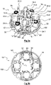
- the picture 3a shows a brush holder 10 according to the invention for a motor vehicle starter.
- This brush holder 10 comprises a support plate 12 of substantially annular shape on which is fixed a set of cages 13.1-13.4 each serving as a housing for a brush 15.1-15.4.
- An axis X of the support plate 12 corresponds to the axis of the brush holder 10.
- the support plate 12 is a one-piece part comprising a metal plate 121 and overmolded layers 122 made on either side of the metal plate 121.
- the overmolded layers 122 are made using a plastic material providing good insulation electric.
- Overmolded diapers 122 at least partially protect the brush support face as well as the opposite face.
- the overmolded layers 122 cover all the areas at risk of the plate 12, that is to say, all the areas where a short circuit could appear.
- the overmolded layers 122 are heat sensitive and deformable from a predetermined temperature.
- the predetermined temperature corresponds to a temperature beyond which the starter and/or its environment would be liable to be damaged.
- the plastic material used for the overmolded layers 122 is a thermoplastic material such as a polyamide PA4.6 or PA6.6 or a polypropylene PPS filled with fiberglass between 40 and 50%. Thermosetting materials can also be envisaged.
- the metal plate 121 is typically obtained by stamping from a cutting steel such as for example FePO5.
- the support plate 12 and the cages 13.1-13.4 that it carries are fixed on a cover (not shown) forming a rear bearing for the rotor shaft of the electric machine.
- the central part of the plate 12 has an orifice 14 through which the assembly that it forms with the brush cages 13.1-13.4 and the brushes 15.1-15.4 is mounted around the rotor shaft of the starter.
- Each brush 15.1-15.4 is slidably mounted inside a cage 13.1-13.4 which is open on the side of the X axis to allow the electrical contacting of the brushes 15.1-15.4 with blades carried by a collector of an electric machine rotor (not shown).
- each cage 13.1-13.4 is produced by bending a thin sheet metal plate so as to substantially form an omega whose end branches are fixed to the plate 12.
- Each cage 13.1-13.4 thus comprises two side walls 17, 18 opposite each other by an upper wall 19.
- the end walls 20, 21 corresponding to the branches of the omega come from lower edges of the side walls 17, 18 of the brush cage 13.1-13.4.
- One of the side walls 17 has a notch 23 to allow passage of the braid 24.1-24.4 of the broom housed in the corresponding cage 13.1-13.4.
- the other side wall 18 has an opening 25 to allow passage of the arm of the corresponding spring.
- each brush cage 13.1-13.4 may include flaps 28, 29 extending on either side of the brush to prevent the dust generated by friction with the blades of the collector alter the operation of the brush holder 10.
- One of the flaps 28 has a recess 30 located in the extension of the notch 23 to allow passage of the braid 24.1-24.4 as close as possible to the collector.
- Each cage 13.1-13.4 further comprises a system 31 for fixing to the plate 12.
- Each fixing system 31 is formed by two pairs of tabs 32.
- the tabs 32 of each pair come from two edges facing the end walls 20, 21.
- a leg 32 of each pair crosses the plate 12 right through via an opening 33 made along its thickness.
- the other leg 32 of each pair bears against one side of the square-shaped inner contour delimiting the orifice 14.
- the legs 32 of each pair are folded towards each other against the plate 12.
- the system fastening 31 comprises at least one rivet passing through the plate 12 and an end wall 20, 21 of the brush cage.
- a spiral spring 35 associated with each cage 13.1-13.4 radially urges the corresponding brush 15.1-15.4 towards the contact blades of the commutator carried by a body of the commutator made of electrically insulating material, such as plastic.
- Each spring 35 is in this case mounted around a retaining system 37 here formed by a pin extending axially with respect to the axis X. This pin 37 is obtained by folding one of the end walls 20 of each cage 13.1-13.4.
- each spring 35 comprises a wound part formed by a plurality of coils.
- the wound part ends with an arm 351 intended to bear against at least part of the rear face of the brush 15.1-15.4.
- the arm 351 is terminated by two parts 352 in contact against bearing faces 38 located on either side of the zone for fixing the electrically conductive braid 24.1-24.4 to the brush.
- the attachment zone between the braid 24.1-24.4 and the brush 15.1-15.4 is recessed with respect to the bearing surfaces 38 in order to maximize a functional distance of use of the brushes 15.1-15.4.
- Brushes 15.1-15.4 have alternating polarities.
- the brushes 15.1 and 15.3 of positive polarity are electrically connected, via their respective braid 24.1, 24.3 to a power wire from the starter contactor.
- These brushes 15.1 and 15.3 and their corresponding cage 13.1 and 13.3 are electrically isolated from the negative polarity for correct operation of the starter.
- This insulation is obtained by the overmolded layers 122 which cover the fields of the openings 33 receiving the legs of the cages of positive polarity 13.1, 13.3, as well as at least partly the inner contour of the plate 12.
- the braids 24.1 and 24.3 may also be covered with an insulating sheath.
- the brushes 15.2 and 15.4 of negative polarity intended for the current return are electrically connected to the ground of the machine by means of their respective braid 24.2, 24.4 welded to the plate 121.
- the flexible braids 24.1-24.4 are advantageously made of copper or copper alloy to facilitate welding on the plate 121.
- the openings 33 receiving the tabs 32 of the cages of negative polarity 13.2 and 13.4 as well as the areas of the inner contour of the plate 12 in contact with other tabs 32 of these cages 13.2, 13.4 are not electrically insulated, so that an electrical contact can occur between the cages of negative polarity 13.2, 13.4 and the plate 121 via the tabs 32. This contact is not harmful to the operation of the starter, insofar as it participates in the establishment of electrical contact between the parts intended to be at the same potential, in this case the ground potential in this application.
- the tabs 32 of the cages 13.1, 13.3 of positive polarity are insulated with respect to the plate 12 while the spring 35 which is mounted compressed applies a force F1 against the brush 15.1, 15.3 so as to keep it constantly in contact with the blades of the collector.
- the spring 35 also applies a force F2 on the cage 13.1, 13.3 via the holding system 37.
- the cages 13.1 and 13.3 cannot however move relative to the plate 12 due to the rigid nature of the assembly. .
- the tabs 32 of the cages of positive polarity 13.1, 13.3 are covered at least in part with an insulating layer 40 sensitive to heat.
- This layer 40 forming a deformable member may be made of the same type of material as that of the overmolded layers 122.
- the plate 12 which is moved towards the cages of positive polarity 13.1, 13.3 following a deformation of the insulating layers 122.
- the plate 12 is electrically connected to the positive polarity.
- the layers 122 take the form of added insulating washers which are fixed on either side of the metal plate 121.
- the spiral spring 35 can also be replaced by a cylindrical spring pressing against the cover to push the corresponding brush against the blades of the commutator.
- the brush holder 10 comprises more than four brushes 15.1-15.4, each brush being able for example to be associated with another brush positioned on the opposite side of the plate 12.
- the brush holder 10 is here a machine brush holder of a motor vehicle starter.
Landscapes
- Engineering & Computer Science (AREA)
- Power Engineering (AREA)
- Microelectronics & Electronic Packaging (AREA)
- Motor Or Generator Current Collectors (AREA)
Description
- L'invention porte sur un démarreur de véhicule automobile comportant un porte-balais muni d'un système de protection thermique,. L'invention trouve une application particulièrement avantageuse, mais non exclusive, avec les démarreurs de systèmes dits "stop and start" permettant l'arrêt et le redémarrage du moteur thermique du véhicule en fonction notamment des conditions de circulation.
- De façon connue en soi, les démarreurs, comprennent un moyen de protection contre les surintensités prenant la forme d'un ou plusieurs fusibles électriques et/ou d'un ou plusieurs disjoncteurs. La
figure 1 montre ainsi un exemple de moteur 1 de démarreur comprenant un fusible 2 monté en série entre une borne d'alimentation 3 de la machine électrique 1 et des enroulements 4.1, 4.2, 4.3, 4.4 du stator dudit moteur. - Le fusible est destiné à fondre pour couper l'alimentation électrique du moteur lorsqu'il est parcouru par un courant prédéterminé maximum. Cela permet d'éviter de détériorer le démarreur ou son environnement à cause de la chaleur produite par une surintensité. Une telle surintensité apparait notamment dans le cas où le rotor du moteur est bloqué en rotation.
- Lorsque la machine fonctionne à vide ou à faible charge (c'est-à-dire qu'elle fonctionne environ entre 0 et 25% de la charge nominale), la vitesse de rotation à vide du rotor entraîne également un échauffement de la machine électrique susceptible d'endommager le démarreur sur la durée. Cet échauffement, dû notamment au frottement mécanique entre les balais et le collecteur, se produit par exemple en phase de survitesse lorsque le pignon du démarreur entraîné par le moteur thermique tourne plus vite que l'arbre entraîné par le rotor du démarreur. Toutefois, dans ce cas, le courant traversant le fusible peut être trop faible pour engendrer une fusion du fusible 2 et cela même sur une longue durée.
- Une solution consisterait donc à choisir un fusible apte à fondre à la fois lorsqu'un courant à vide traverse le fusible pendant une durée dépassant une première durée prédéterminée et lorsqu'un courant traverse la machine électrique tournante ayant son rotor bloqué pendant une durée dépassant une seconde durée prédéterminée. De tels fusibles sont toutefois beaucoup plus volumineux qu'un fusible de taille standard, ce qui rend leur intégration quasiment impossible dans le démarreur.
- Le document
FR2977408 - Le document
US 6 188 154 B1 décrit dans une application différente que celles des démarreurs, un système de fixation sensible à la chaleur. - Les documents
DE 10 2010 030870 A1 ,DE 100 59 680 A1 ,US 2007/108864 A1 etDE 20 2010 002664 U1 sont des documents qui illustre l'art antérieur de l'invention. - L'invention vise à remédier efficacement à cet inconvénient en proposant un démarreur de véhicule automobile selon la revendication 1.
- Ainsi, l'invention permet d'établir un court-circuit entre la cage à balai de première polarité et la platine de support connectée à la deuxième polarité pour activer le moyen de protection thermique en cas de surchauffe sans avoir à ajouter de pièce supplémentaire à l'intérieur des cages à balais. On facilite ainsi le montage de l'ensemble porte-balais.
- Selon une réalisation non revendiquée, ledit organe déformable est constitué par au moins une couche isolante recouvrant au moins en partie une plaque métallique de ladite platine de support.
- Selon une réalisation non revendiquée, ladite couche isolante est surmoulée sur ladite plaque métallique.
- Selon l'invention définie dans la revendication 1, ledit organe déformable est formé par une couche de matériau électriquement isolant recouvrant au moins en partie un système de fixation de ladite première cage à ladite platine de support.
- Selon une réalisation, le système de fixation comporte au moins une patte recouverte au moins en partie d'une couche de matériau électriquement isolant.
- Selon une réalisation, ledit moyen de déplacement est formé par un ressort à spirale monté sur un système de maintien dudit ressort appartenant à ladite première cage.
- Selon une réalisation, le système de maintien est constitué par un pion issu d'une paroi de ladite première cage.
- Selon une réalisation, ledit organe déformable est réalisé dans un matériau plastique.
- Selon une réalisation, le matériau plastique est une matière thermoplastique telle qu'un polyamide PA4.6 ou PA6.6, ou un polypropylène PPS chargé en fibre de verre entre 40 et 50%.
- Selon une réalisation, le matériau plastique est une matière thermodurcissable.
- Selon une réalisation, ledit porte-balais comporte deux balais de première polarité et deux balais de deuxième polarité.
- Selon une réalisation, la première polarité correspond à une polarité positive tandis que la deuxième polarité à laquelle est reliée électriquement ladite platine de support correspond à une masse du démarreur.
- L'invention sera mieux comprise à la lecture de la description qui suit et à l'examen des figures qui l'accompagnent. Ces figures ne sont données qu'à titre illustratif mais nullement limitatif de l'invention.
- La
figure 1 , déjà décrite, représente un schéma de principe d'un moteur électrique de démarreur de véhicule automobile muni d'un moyen de protection thermique; - Les
figures 2a et 2b sont des représentations en perspective de la platine de support du porte-balais selon la présente invention suivant deux angles de vue différents; - Les
figures 3a et 3b montrent respectivement des vues en perspective et de dessous d'un porte-balais selon la présente invention; - La
figure 4 montre une vue en perspective d'une cage à balai utilisée avec le porte-balais selon la présente invention; - Les
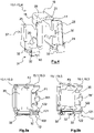
figures 5a et 5b sont des vues de côté d'une cage à balai et de la platine de support respectivement avant et après la déformation d'une couche isolante recouvrant la platine de support. - Les éléments identiques, similaires, ou analogues conservent la même référence d'une figure à l'autre.
- La
figure 3a montre un porte-balais 10 selon l'invention pour démarreur de véhicule automobile. Ce porte-balais 10 comporte une platine de support 12 de forme sensiblement annulaire sur laquelle est fixé un ensemble de cages 13.1-13.4 servant chacune de logement à un balai 15.1-15.4. Un axe X de la platine de support 12 correspond à l'axe du porte-balais 10. - Comme cela est bien visible sur les
figures 2a et 2b , la platine de support 12 est une pièce monobloc comportant une plaque métallique 121 et des couches surmoulées 122 réalisées de part et d'autre de la plaque métallique 121. Les couches surmoulées 122 sont réalisées au moyen d'une matière plastique assurant une bonne isolation électrique. Les couches surmoulées 122 protègent au moins en partie la face support de balais ainsi que la face opposée. Les couches surmoulées 122 recouvrent toutes les zones à risque de la platine 12, c'est-à-dire, toutes les zones où pourrait apparaître un court-circuit. - Les couches surmoulées 122 sont sensible à la chaleur et déformables à partir d'une température prédéterminée. La température prédéterminée correspond à une température au-delà de laquelle le démarreur et/ou son environnement seraient susceptibles d'être endommagés.
- Différentes matières plastiques sont utilisables selon les applications et les contraintes qui s'imposent à celles-ci. Typiquement, la matière plastique utilisée pour les couches surmoulées 122 est une matière thermoplastique telle qu'un polyamide PA4.6 ou PA6.6 ou un polypropylène PPS chargé en fibre de verre entre 40 et 50%. Des matières thermodurcissables peuvent aussi être envisagées. La plaque métallique 121 est typiquement obtenue par emboutissage à partir d'un acier à découper tel que par exemple le FePO5.
- La platine de support 12 et les cages 13.1-13.4 qu'elle porte viennent se fixer sur un capot (non représenté) formant un palier arrière pour l'arbre de rotor de la machine électrique. En outre, la partie centrale de la platine 12 comporte un orifice 14 par lequel l'ensemble qu'elle forme avec les cages à balais 13.1-13.4 et les balais 15.1-15.4 est monté autour de l'arbre rotor du démarreur.
- Chaque balai 15.1-15.4 est monté à coulissement à l'intérieur d'une cage 13.1-13.4 laquelle est ouverte du côté de l'axe X pour permettre la mise en contact électrique des balais 15.1-15.4 avec des lames portées par un collecteur d'un rotor de machine électrique (non représenté).
- Plus précisément, comme cela est bien visible sur la
figure 4 , chaque cage 13.1-13.4 est réalisée par pliage d'une plaquette de tôle mince de manière à former sensiblement un oméga dont les branches d'extrémité sont fixées sur la platine 12. Chaque cage 13.1-13.4 comporte ainsi deux parois latérales 17, 18 parallèles en vis-à-vis reliées entre elles par une paroi supérieure 19. Les parois d'extrémité 20, 21 correspondant aux branches de l'oméga sont issues des bords inférieurs des parois latérales 17, 18 de la cage à balai 13.1-13.4. Une des parois latérales 17 présente une échancrure 23 pour autoriser le passage de la tresse 24.1-24.4 du balai logé dans la cage 13.1-13.4 correspondante. L'autre paroi latérale 18 présente une ouverture 25 pour autoriser le passage du bras du ressort correspondant. Du côté de la face débouchant du côté du collecteur, chaque cage à balai 13.1-13.4 pourra comporter des volets 28, 29 s'étendant de part et d'autre du balai pour éviter que les poussières générées par les frottements avec les lames du collecteur viennent altérer le fonctionnement du porte-balais 10. Un des volets 28 présente une creusure 30 située dans le prolongement de l'échancrure 23 pour autoriser le passage de la tresse 24.1-24.4 au plus proche du collecteur. - Chaque cage 13.1-13.4 comporte en outre un système 31 de fixation à la platine 12. Chaque système 31 de fixation est formé par deux paires de pattes 32. Les pattes 32 de chaque paires sont issues de deux bords en vis-à-vis des parois d'extrémité 20, 21. Comme on peut le voir sur la
figure 3b , une patte 32 de chaque paire traverse la platine 12 de part en part via une ouverture 33 réalisée suivant son épaisseur. L'autre patte 32 de chaque paire est en appui contre un côté du contour intérieur de forme carrée délimitant l'orifice 14. Les pattes 32 de chaque paire sont rabattues l'une vers l'autre contre la platine 12. Alternativement, le système de fixation 31 comporte au moins un rivet traversant la platine 12 et une paroi d'extrémité 20, 21 de la cage à balai. - Par ailleurs, un ressort à spirales 35 associé à chaque cage 13.1-13.4 sollicite radialement le balai 15.1-15.4 correspondant vers des lames de contact du collecteur portées par un corps du collecteur en matière électriquement isolante, telle que de la matière plastique. Chaque ressort 35 est en l'occurrence monté autour d'un système de maintien 37 ici formé par un pion s'étendant axialement par rapport à l'axe X. Ce pion 37 est obtenu par pliage d'une des parois d'extrémité 20 de chaque cage 13.1-13.4.
- Comme on peut le voir sur la
figure 3a , chaque ressort 35 comporte une partie enroulée formée par une pluralité de spires. La partie enroulée se termine par un bras 351 destiné à venir en appui contre au moins une partie de la face arrière du balai 15.1-15.4. En l'occurrence, le bras 351 est terminé par deux parties 352 en contact contre des faces d'appui 38 situées de part et d'autre de la zone de fixation de la tresse 24.1-24.4 électriquement conductrice au balai. La zone de fixation entre la tresse 24.1-24.4 et le balai 15.1-15.4 est en retrait par rapport aux faces d'appui 38 afin de maximiser une distance fonctionnelle d'utilisation des balais 15.1-15.4. - Les balais 15.1-15.4 présentent des polarités alternées. Ainsi, les balais 15.1 et 15.3 de polarité positive sont reliés électriquement, via leur tresse respective 24.1, 24.3 à un fil d'alimentation issu du contacteur du démarreur. Ces balais 15.1 et 15.3 et leur cage 13.1 et 13.3 correspondante sont isolés électriquement de la polarité négative pour un bon fonctionnement du démarreur. Cette isolation est obtenue par les couches surmoulées 122 qui recouvrent les champs des ouvertures 33 recevant les pattes des cages de polarité positive 13.1, 13.3, ainsi qu'au moins en partie le contour intérieur de la platine 12. Les tresses 24.1 et 24.3 pourront également être recouvertes d'une gaine isolante.
- Par ailleurs, les balais 15.2 et 15.4 de polarité négative destinés au retour de courant sont reliés électriquement à la masse de la machine au moyen de leur tresse respective 24.2, 24.4 soudée sur la plaque 121. Les tresses souples 24.1-24.4 sont avantageusement en cuivre ou en alliage de cuivre pour faciliter le soudage sur la plaque 121. De préférence, les ouvertures 33 recevant les pattes 32 des cages de polarité négative 13.2 et 13.4 ainsi que les zones du contour intérieur de la platine 12 en contact avec autres pattes 32 de ces cages 13.2, 13.4 ne sont pas isolées électriquement, en sorte qu'un contact électrique peut intervenir entre les cages de polarité négative 13.2, 13.4 et la plaque 121 via les pattes 32. Ce contact n'est pas nuisible au fonctionnement du démarreur, dans la mesure où il participe à l'établissement du contact électrique entre les pièces destinées à être au même potentiel, en l'occurrence le potentiel de masse dans cette application.
- On décrit ci-après, en référence aux
figures 5a et 5b , l'activation du fusible 2 du démarreur en cas de surchauffe pour assurer sa protection. - En fonctionnement normal, c'est-à-dire lorsque la température de déformation des couches surmoulées 122 n'a pas encore été atteinte, les pattes 32 des cages 13.1, 13.3 de polarité positive sont isolées par rapport à la platine 12 tandis que le ressort 35 qui est monté compressé applique un effort F1 contre le balai 15.1, 15.3 de manière à le maintenir constamment en contact avec les lames du collecteur. En réaction, le ressort 35 applique également un effort F2 sur la cage 13.1, 13.3 via le système de maintien 37. Les cages 13.1 et 13.3 ne peuvent toutefois pas se déplacer par rapport à la platine 12 du fait du caractère rigide de l'ensemble.
- Lorsqu'il se produit une surchauffe causée par exemple par un fonctionnement à vide du démarreur pendant une longue durée, la température de déformation des couches isolantes 122 est atteinte. L'effort de réaction F2 exercé par le ressort 35 sur le système de maintien 37 engendre alors un pivotement des cages de polarité positive 13.1 et 13.3 par rapport à la platine 12, en sorte qu'au moins une patte 32 d'une cage 13.1, 13.3 vient en contact avec la plaque 121 reliée à la masse pour établir un court-circuit. Ce court-circuit engendre une augmentation considérable du courant parcourant la machine, ce qui a pour effet de faire fondre le fusible 2 du démarreur. L'invention permet ainsi d'assurer une protection du démarreur alors que le courant traversant la machine lors d'un fonctionnement à vide du moteur provoquant une surchauffe ne permet normalement pas de faire fondre le fusible 2.
- L'homme du métier pourra bien entendu modifier la configuration du porte-balais 10 précédemment décrit sans sortir du cadre de l'invention, en respectant la portée des revendications annexées. Ainsi, en variante, comme cela est visible à la
figure 4 , les pattes 32 des cages de polarité positive 13.1, 13.3 sont recouvertes au moins en partie d'une couche isolante 40 sensible à la chaleur. Cette couche 40 formant un organe déformable pourra être réalisée dans le même type de matériau que celui des couches surmoulées 122. - Alternativement, c'est la platine 12 qui est déplacée vers les cages de polarité positive 13.1, 13.3 suite à une déformation des couches isolantes 122. Alternativement, la platine 12 est reliée électriquement à la polarité positive.
- En variante, les couches 122 prennent la forme de rondelles isolantes rapportées qui sont fixées de part et d'autre de la plaque métallique 121. Le ressort à spirales 35 peut également être remplacé par un ressort cylindrique prenant appui sur le capot pour pousser le balai correspondant contre les lames du collecteur.
- En variante, le porte-balais 10 comporte plus de quatre balais 15.1-15.4, chaque balai pouvant par exemple être associé à un autre balai positionné du côté opposé de la platine 12.
- Le porte-balais 10 est ici un porte-balais de machine d'un démarreur de véhicule automobile.
Claims (9)
- Démarreur de véhicule automobile comportant un porte-balais (10) comportant un arbre rotor, au moins une première cage (13.1, 13.3) électriquement conductrice recevant un premier balai (15.1, 15.3) de première polarité, au moins une deuxième cage (13.2, 13.4) recevant un deuxième balai (15.2, 15.4) de deuxième polarité différente de la première polarité, au moins une platine de support (12) sur laquelle sont fixés la première (13.1, 13.3) et la deuxième (13.2, 13.4) cages, ladite platine de support (12) étant reliée électriquement à la deuxième polarité, et un organe (122, 40) sensible à la chaleur déformable à partir d'une température prédéterminée, ledit organe déformable (122, 40) est agencé pour isoler électriquement ladite première cage (13.1, 13.3) par rapport à ladite platine de support (12), suite à une déformation dudit organe déformable (122, 40), un contact entre ladite première cage (13.1, 13.3) et ladite platine de support (12) est établi, ledit organe déformable est formé par une couche (40) de matériau électriquement isolant recouvrant au moins en partie un système de fixation (31) de ladite première cage (13.1, 13.3) à ladite platine de support (12) et le démarreur comporte un moyen de déplacement (35) de ladite première cage de manière à établir le contact suite à la déformation.
- Démarreur de véhicule selon la revendication 1, caractérisé en ce que le système de fixation (31) comporte au moins une patte (32) recouverte au moins en partie d'une couche (40) de matériau électriquement isolant.
- Démarreur de véhicule selon l'une quelconque des revendications 1 et 2, caractérisé en ce que ledit moyen de déplacement (35) est formé par un ressort à spirale monté sur un système de maintien (37) dudit ressort (35) appartenant à ladite première cage (13.1, 13.3).
- Démarreur de véhicule selon la revendication 3, caractérisé en ce que ledit système de maintien (37) est constitué par un pion issu d'une paroi de ladite première cage (13.1, 13.3).
- Démarreur de véhicule selon l'une quelconque des revendications 1 à 4, caractérisé en ce que ledit organe déformable (122, 40) est réalisé dans un matériau plastique.
- Démarreur de véhicule selon la revendication 5, caractérisé en ce que le matériau plastique est une matière thermoplastique telle qu'un polyamide PA4.6 ou PA6.6, ou un polypropylène PPS chargé en fibre de verre entre 40 et 50%.
- Démarreur de véhicule selon la revendication 6, caractérisé en ce que le matériau plastique est une matière thermodurcissable.
- Démarreur de véhicule selon l'une quelconque des revendications 1 à 7, caractérisé en ce qu'il comporte deux balais (15.1, 15.3) de première polarité et deux balais (15.2, 15.4) de deuxième polarité.
- Démarreur de véhicule selon l'une quelconque des revendications 1 à 8, caractérisé en ce que la première polarité correspond à une polarité positive tandis que la deuxième polarité à laquelle est reliée électriquement ladite platine de support (12) correspond à une masse du démarreur.
Applications Claiming Priority (2)
| Application Number | Priority Date | Filing Date | Title |
|---|---|---|---|
| FR1450573A FR3016754B1 (fr) | 2014-01-23 | 2014-01-23 | Porte-balais pour demarreur de vehicule automobile muni d'un systeme de protection thermique et demarreur de vehicule automobile correspondant |
| PCT/FR2015/050099 WO2015110743A2 (fr) | 2014-01-23 | 2015-01-15 | Porte-balais pour demarreur de vehicule automobile muni d'un systeme de protection thermique et demarreur de vehicule automobile correspondant |
Publications (2)
| Publication Number | Publication Date |
|---|---|
| EP3097630A2 EP3097630A2 (fr) | 2016-11-30 |
| EP3097630B1 true EP3097630B1 (fr) | 2022-03-30 |
Family
ID=50489330
Family Applications (1)
| Application Number | Title | Priority Date | Filing Date |
|---|---|---|---|
| EP15705637.5A Active EP3097630B1 (fr) | 2014-01-23 | 2015-01-15 | Porte-balais pour demarreur de vehicule automobile muni d'un systeme de protection thermique et demarreur de vehicule automobile correspondant |
Country Status (5)
| Country | Link |
|---|---|
| US (1) | US10050489B2 (fr) |
| EP (1) | EP3097630B1 (fr) |
| CN (1) | CN106416007B (fr) |
| FR (1) | FR3016754B1 (fr) |
| WO (1) | WO2015110743A2 (fr) |
Families Citing this family (9)
| Publication number | Priority date | Publication date | Assignee | Title |
|---|---|---|---|---|
| CN105720744B (zh) | 2014-12-05 | 2020-06-09 | 法雷奥电机设备公司 | 设置有热保护系统的机动车辆起动器 |
| FR3032840B1 (fr) * | 2015-02-13 | 2018-04-13 | Valeo Equip Electr Moteur | Porte-balais |
| FR3038159B1 (fr) | 2015-06-26 | 2018-07-13 | Valeo Equipements Electriques Moteur | Demarreur de vehicule automobile muni d'un systeme de protection thermique |
| FR3055488A1 (fr) * | 2016-09-01 | 2018-03-02 | Valeo Equipements Electriques Moteur | Moteur electrique muni d'un porte-balais pour demarreur |
| FR3069977A1 (fr) * | 2017-08-04 | 2019-02-08 | Valeo Equipements Electriques Moteur | Porte balais pour demarreur de vehicule automobile |
| FR3069983A1 (fr) * | 2017-08-04 | 2019-02-08 | Valeo Equipements Electriques Moteur | Ensemble cage a balai |
| FR3069982A1 (fr) * | 2017-08-04 | 2019-02-08 | Valeo Equipements Electriques Moteur | Porte balais pour demarreur de vehicule automobile |
| FR3076116A1 (fr) * | 2017-12-21 | 2019-06-28 | Valeo Equipements Electriques Moteur | Porte-balais de demarreur configure pour assurer un maintien de sa platine de support contre une culasse de moteur electrique |
| FR3079365B1 (fr) * | 2018-03-23 | 2020-09-04 | Valeo Equip Electr Moteur | Porte-balais de demarreur de moteur thermique muni de cages a balais de forme modifiee |
Citations (1)
| Publication number | Priority date | Publication date | Assignee | Title |
|---|---|---|---|---|
| US6188154B1 (en) * | 1999-03-12 | 2001-02-13 | Robert Bosch Gmbh | Electric motor with thermal safety |
Family Cites Families (8)
| Publication number | Priority date | Publication date | Assignee | Title |
|---|---|---|---|---|
| DE10059680A1 (de) * | 2000-12-01 | 2002-06-06 | Bosch Gmbh Robert | Startvorrichtung |
| CH695974A5 (de) * | 2002-10-15 | 2006-10-31 | Team Orion Europe Sa | Gleichstrommotor mit Kollektor und Kohlebüsten. |
| JP2007143207A (ja) * | 2005-11-14 | 2007-06-07 | Asmo Co Ltd | 回転電機及び車両用送風機 |
| DE102009046198A1 (de) * | 2009-10-30 | 2011-05-05 | Robert Bosch Gmbh | Kohlebürste mit veränderter Temperaturgrenze |
| DE202010002664U1 (de) | 2010-02-23 | 2011-07-12 | Brose Fahrzeugteile GmbH & Co. Kommanditgesellschaft, Würzburg | Elektromotor zum Antrieb einer Kraftfahrzeugkomponente |
| DE102010030870A1 (de) * | 2010-07-02 | 2012-01-05 | Robert Bosch Gmbh | Elektromotor |
| FR2977408B1 (fr) | 2011-06-30 | 2017-04-14 | Valeo Equip Electr Moteur | Systeme de protection d'echauffement pour une machine electrique tournante, notamment un demarreur |
| DE102012010483A1 (de) * | 2012-05-26 | 2013-11-28 | Brose Fahrzeugteile GmbH & Co. Kommanditgesellschaft, Würzburg | Bürstensystem für einen Elektromotor |
-
2014
- 2014-01-23 FR FR1450573A patent/FR3016754B1/fr not_active Expired - Fee Related
-
2015
- 2015-01-15 EP EP15705637.5A patent/EP3097630B1/fr active Active
- 2015-01-15 WO PCT/FR2015/050099 patent/WO2015110743A2/fr not_active Ceased
- 2015-01-15 CN CN201580005631.5A patent/CN106416007B/zh active Active
- 2015-01-15 US US15/107,625 patent/US10050489B2/en active Active
Patent Citations (1)
| Publication number | Priority date | Publication date | Assignee | Title |
|---|---|---|---|---|
| US6188154B1 (en) * | 1999-03-12 | 2001-02-13 | Robert Bosch Gmbh | Electric motor with thermal safety |
Also Published As
| Publication number | Publication date |
|---|---|
| US20160336832A1 (en) | 2016-11-17 |
| FR3016754B1 (fr) | 2016-01-01 |
| WO2015110743A2 (fr) | 2015-07-30 |
| EP3097630A2 (fr) | 2016-11-30 |
| WO2015110743A3 (fr) | 2016-01-14 |
| US10050489B2 (en) | 2018-08-14 |
| CN106416007A (zh) | 2017-02-15 |
| FR3016754A1 (fr) | 2015-07-24 |
| CN106416007B (zh) | 2020-02-18 |
Similar Documents
| Publication | Publication Date | Title |
|---|---|---|
| WO2015110743A2 (fr) | Porte-balais pour demarreur de vehicule automobile muni d'un systeme de protection thermique et demarreur de vehicule automobile correspondant | |
| EP3066750B1 (fr) | Porte-balais de machine electrique pour vehicule et demarreur correspondant | |
| EP3314711B1 (fr) | Démarreur de véhicule automobile muni d'un système de protection thermique | |
| WO2014049290A1 (fr) | Cage a balai pour porte-balai de machine electrique et porte-balais correspondant | |
| EP2727226A2 (fr) | Systeme de protection d'echauffement pour une machine electrique tournante, notamment un demarreur | |
| EP3231067B1 (fr) | Cage à balai améliorée pour démarreur de véhicule automobile, porte-balais, moteur électrique, et démarreur de véhicule automobile correspondants | |
| FR3048733B1 (fr) | Demarreur de vehicule automobile muni d'une protection thermique amelioree | |
| FR3069983A1 (fr) | Ensemble cage a balai | |
| EP3231046A1 (fr) | Ensemble comportant une cage à balai et un ressort à spirales, porte-balais, moteur électrique, et démarreur de véhicule automobile correspondants | |
| FR3069981A1 (fr) | Porte balais pour demarreur de vehicule automobile | |
| FR3069982A1 (fr) | Porte balais pour demarreur de vehicule automobile | |
| EP3326247A1 (fr) | Porte-balais ameliore de moteur electrique de demarreur de vehicule automobile | |
| EP3259831A1 (fr) | Ressort a spirales d'un porte-balais | |
| FR3037199A1 (fr) | Demarreur de vehicule automobile muni d'un organe de protection thermique | |
| FR3069977A1 (fr) | Porte balais pour demarreur de vehicule automobile | |
| FR3055488A1 (fr) | Moteur electrique muni d'un porte-balais pour demarreur | |
| FR3050880A1 (fr) | Dispositif porte-balais pour demarreur | |
| FR3030928A1 (fr) | Ensemble pour porte-balais de moteur electrique de demarreur de vehicule automobile | |
| WO2016097549A1 (fr) | Ensemble pour porte-balais de moteur electrique de demarreur de vehicule automobile | |
| WO2016128650A2 (fr) | Porte-balais | |
| FR3050881A1 (fr) | Dispositif porte-balais pour demarreur | |
| EP3096417A1 (fr) | Ensemble pour porte-balais de moteur électrique de démarreur de véhicule automobile | |
| FR2853460A1 (fr) | Collecteur pour moteur electrique |
Legal Events
| Date | Code | Title | Description |
|---|---|---|---|
| PUAI | Public reference made under article 153(3) epc to a published international application that has entered the european phase |
Free format text: ORIGINAL CODE: 0009012 |
|
| 17P | Request for examination filed |
Effective date: 20160719 |
|
| AK | Designated contracting states |
Kind code of ref document: A2 Designated state(s): AL AT BE BG CH CY CZ DE DK EE ES FI FR GB GR HR HU IE IS IT LI LT LU LV MC MK MT NL NO PL PT RO RS SE SI SK SM TR |
|
| AX | Request for extension of the european patent |
Extension state: BA ME |
|
| DAX | Request for extension of the european patent (deleted) | ||
| STAA | Information on the status of an ep patent application or granted ep patent |
Free format text: STATUS: EXAMINATION IS IN PROGRESS |
|
| 17Q | First examination report despatched |
Effective date: 20191210 |
|
| GRAP | Despatch of communication of intention to grant a patent |
Free format text: ORIGINAL CODE: EPIDOSNIGR1 |
|
| STAA | Information on the status of an ep patent application or granted ep patent |
Free format text: STATUS: GRANT OF PATENT IS INTENDED |
|
| INTG | Intention to grant announced |
Effective date: 20210329 |
|
| GRAJ | Information related to disapproval of communication of intention to grant by the applicant or resumption of examination proceedings by the epo deleted |
Free format text: ORIGINAL CODE: EPIDOSDIGR1 |
|
| STAA | Information on the status of an ep patent application or granted ep patent |
Free format text: STATUS: EXAMINATION IS IN PROGRESS |
|
| INTC | Intention to grant announced (deleted) | ||
| GRAS | Grant fee paid |
Free format text: ORIGINAL CODE: EPIDOSNIGR3 |
|
| STAA | Information on the status of an ep patent application or granted ep patent |
Free format text: STATUS: GRANT OF PATENT IS INTENDED |
|
| GRAP | Despatch of communication of intention to grant a patent |
Free format text: ORIGINAL CODE: EPIDOSNIGR1 |
|
| INTG | Intention to grant announced |
Effective date: 20210924 |
|
| GRAJ | Information related to disapproval of communication of intention to grant by the applicant or resumption of examination proceedings by the epo deleted |
Free format text: ORIGINAL CODE: EPIDOSDIGR1 |
|
| GRAL | Information related to payment of fee for publishing/printing deleted |
Free format text: ORIGINAL CODE: EPIDOSDIGR3 |
|
| STAA | Information on the status of an ep patent application or granted ep patent |
Free format text: STATUS: EXAMINATION IS IN PROGRESS |
|
| GRAP | Despatch of communication of intention to grant a patent |
Free format text: ORIGINAL CODE: EPIDOSNIGR1 |
|
| STAA | Information on the status of an ep patent application or granted ep patent |
Free format text: STATUS: GRANT OF PATENT IS INTENDED |
|
| INTC | Intention to grant announced (deleted) | ||
| GRAA | (expected) grant |
Free format text: ORIGINAL CODE: 0009210 |
|
| STAA | Information on the status of an ep patent application or granted ep patent |
Free format text: STATUS: THE PATENT HAS BEEN GRANTED |
|
| INTG | Intention to grant announced |
Effective date: 20220210 |
|
| AK | Designated contracting states |
Kind code of ref document: B1 Designated state(s): AL AT BE BG CH CY CZ DE DK EE ES FI FR GB GR HR HU IE IS IT LI LT LU LV MC MK MT NL NO PL PT RO RS SE SI SK SM TR |
|
| REG | Reference to a national code |
Ref country code: GB Ref legal event code: FG4D Free format text: NOT ENGLISH |
|
| REG | Reference to a national code |
Ref country code: CH Ref legal event code: EP |
|
| REG | Reference to a national code |
Ref country code: AT Ref legal event code: REF Ref document number: 1480089 Country of ref document: AT Kind code of ref document: T Effective date: 20220415 |
|
| REG | Reference to a national code |
Ref country code: DE Ref legal event code: R096 Ref document number: 602015077838 Country of ref document: DE |
|
| REG | Reference to a national code |
Ref country code: IE Ref legal event code: FG4D Free format text: LANGUAGE OF EP DOCUMENT: FRENCH |
|
| REG | Reference to a national code |
Ref country code: LT Ref legal event code: MG9D |
|
| PG25 | Lapsed in a contracting state [announced via postgrant information from national office to epo] |
Ref country code: SE Free format text: LAPSE BECAUSE OF FAILURE TO SUBMIT A TRANSLATION OF THE DESCRIPTION OR TO PAY THE FEE WITHIN THE PRESCRIBED TIME-LIMIT Effective date: 20220330 Ref country code: RS Free format text: LAPSE BECAUSE OF FAILURE TO SUBMIT A TRANSLATION OF THE DESCRIPTION OR TO PAY THE FEE WITHIN THE PRESCRIBED TIME-LIMIT Effective date: 20220330 Ref country code: NO Free format text: LAPSE BECAUSE OF FAILURE TO SUBMIT A TRANSLATION OF THE DESCRIPTION OR TO PAY THE FEE WITHIN THE PRESCRIBED TIME-LIMIT Effective date: 20220630 Ref country code: LT Free format text: LAPSE BECAUSE OF FAILURE TO SUBMIT A TRANSLATION OF THE DESCRIPTION OR TO PAY THE FEE WITHIN THE PRESCRIBED TIME-LIMIT Effective date: 20220330 Ref country code: HR Free format text: LAPSE BECAUSE OF FAILURE TO SUBMIT A TRANSLATION OF THE DESCRIPTION OR TO PAY THE FEE WITHIN THE PRESCRIBED TIME-LIMIT Effective date: 20220330 Ref country code: BG Free format text: LAPSE BECAUSE OF FAILURE TO SUBMIT A TRANSLATION OF THE DESCRIPTION OR TO PAY THE FEE WITHIN THE PRESCRIBED TIME-LIMIT Effective date: 20220630 |
|
| REG | Reference to a national code |
Ref country code: NL Ref legal event code: MP Effective date: 20220330 |
|
| REG | Reference to a national code |
Ref country code: AT Ref legal event code: MK05 Ref document number: 1480089 Country of ref document: AT Kind code of ref document: T Effective date: 20220330 |
|
| PG25 | Lapsed in a contracting state [announced via postgrant information from national office to epo] |
Ref country code: LV Free format text: LAPSE BECAUSE OF FAILURE TO SUBMIT A TRANSLATION OF THE DESCRIPTION OR TO PAY THE FEE WITHIN THE PRESCRIBED TIME-LIMIT Effective date: 20220330 Ref country code: GR Free format text: LAPSE BECAUSE OF FAILURE TO SUBMIT A TRANSLATION OF THE DESCRIPTION OR TO PAY THE FEE WITHIN THE PRESCRIBED TIME-LIMIT Effective date: 20220701 Ref country code: FI Free format text: LAPSE BECAUSE OF FAILURE TO SUBMIT A TRANSLATION OF THE DESCRIPTION OR TO PAY THE FEE WITHIN THE PRESCRIBED TIME-LIMIT Effective date: 20220330 |
|
| PG25 | Lapsed in a contracting state [announced via postgrant information from national office to epo] |
Ref country code: NL Free format text: LAPSE BECAUSE OF FAILURE TO SUBMIT A TRANSLATION OF THE DESCRIPTION OR TO PAY THE FEE WITHIN THE PRESCRIBED TIME-LIMIT Effective date: 20220330 |
|
| PG25 | Lapsed in a contracting state [announced via postgrant information from national office to epo] |
Ref country code: SM Free format text: LAPSE BECAUSE OF FAILURE TO SUBMIT A TRANSLATION OF THE DESCRIPTION OR TO PAY THE FEE WITHIN THE PRESCRIBED TIME-LIMIT Effective date: 20220330 Ref country code: SK Free format text: LAPSE BECAUSE OF FAILURE TO SUBMIT A TRANSLATION OF THE DESCRIPTION OR TO PAY THE FEE WITHIN THE PRESCRIBED TIME-LIMIT Effective date: 20220330 Ref country code: RO Free format text: LAPSE BECAUSE OF FAILURE TO SUBMIT A TRANSLATION OF THE DESCRIPTION OR TO PAY THE FEE WITHIN THE PRESCRIBED TIME-LIMIT Effective date: 20220330 Ref country code: PT Free format text: LAPSE BECAUSE OF FAILURE TO SUBMIT A TRANSLATION OF THE DESCRIPTION OR TO PAY THE FEE WITHIN THE PRESCRIBED TIME-LIMIT Effective date: 20220801 Ref country code: ES Free format text: LAPSE BECAUSE OF FAILURE TO SUBMIT A TRANSLATION OF THE DESCRIPTION OR TO PAY THE FEE WITHIN THE PRESCRIBED TIME-LIMIT Effective date: 20220330 Ref country code: EE Free format text: LAPSE BECAUSE OF FAILURE TO SUBMIT A TRANSLATION OF THE DESCRIPTION OR TO PAY THE FEE WITHIN THE PRESCRIBED TIME-LIMIT Effective date: 20220330 Ref country code: CZ Free format text: LAPSE BECAUSE OF FAILURE TO SUBMIT A TRANSLATION OF THE DESCRIPTION OR TO PAY THE FEE WITHIN THE PRESCRIBED TIME-LIMIT Effective date: 20220330 Ref country code: AT Free format text: LAPSE BECAUSE OF FAILURE TO SUBMIT A TRANSLATION OF THE DESCRIPTION OR TO PAY THE FEE WITHIN THE PRESCRIBED TIME-LIMIT Effective date: 20220330 |
|
| PG25 | Lapsed in a contracting state [announced via postgrant information from national office to epo] |
Ref country code: PL Free format text: LAPSE BECAUSE OF FAILURE TO SUBMIT A TRANSLATION OF THE DESCRIPTION OR TO PAY THE FEE WITHIN THE PRESCRIBED TIME-LIMIT Effective date: 20220330 Ref country code: IS Free format text: LAPSE BECAUSE OF FAILURE TO SUBMIT A TRANSLATION OF THE DESCRIPTION OR TO PAY THE FEE WITHIN THE PRESCRIBED TIME-LIMIT Effective date: 20220730 Ref country code: AL Free format text: LAPSE BECAUSE OF FAILURE TO SUBMIT A TRANSLATION OF THE DESCRIPTION OR TO PAY THE FEE WITHIN THE PRESCRIBED TIME-LIMIT Effective date: 20220330 |
|
| REG | Reference to a national code |
Ref country code: DE Ref legal event code: R097 Ref document number: 602015077838 Country of ref document: DE |
|
| PG25 | Lapsed in a contracting state [announced via postgrant information from national office to epo] |
Ref country code: DK Free format text: LAPSE BECAUSE OF FAILURE TO SUBMIT A TRANSLATION OF THE DESCRIPTION OR TO PAY THE FEE WITHIN THE PRESCRIBED TIME-LIMIT Effective date: 20220330 |
|
| PLBE | No opposition filed within time limit |
Free format text: ORIGINAL CODE: 0009261 |
|
| STAA | Information on the status of an ep patent application or granted ep patent |
Free format text: STATUS: NO OPPOSITION FILED WITHIN TIME LIMIT |
|
| 26N | No opposition filed |
Effective date: 20230103 |
|
| PG25 | Lapsed in a contracting state [announced via postgrant information from national office to epo] |
Ref country code: SI Free format text: LAPSE BECAUSE OF FAILURE TO SUBMIT A TRANSLATION OF THE DESCRIPTION OR TO PAY THE FEE WITHIN THE PRESCRIBED TIME-LIMIT Effective date: 20220330 |
|
| P01 | Opt-out of the competence of the unified patent court (upc) registered |
Effective date: 20230528 |
|
| PG25 | Lapsed in a contracting state [announced via postgrant information from national office to epo] |
Ref country code: IT Free format text: LAPSE BECAUSE OF FAILURE TO SUBMIT A TRANSLATION OF THE DESCRIPTION OR TO PAY THE FEE WITHIN THE PRESCRIBED TIME-LIMIT Effective date: 20220330 |
|
| REG | Reference to a national code |
Ref country code: CH Ref legal event code: PL |
|
| GBPC | Gb: european patent ceased through non-payment of renewal fee |
Effective date: 20230115 |
|
| PG25 | Lapsed in a contracting state [announced via postgrant information from national office to epo] |
Ref country code: LU Free format text: LAPSE BECAUSE OF NON-PAYMENT OF DUE FEES Effective date: 20230115 |
|
| REG | Reference to a national code |
Ref country code: BE Ref legal event code: MM Effective date: 20230131 |
|
| PG25 | Lapsed in a contracting state [announced via postgrant information from national office to epo] |
Ref country code: LI Free format text: LAPSE BECAUSE OF NON-PAYMENT OF DUE FEES Effective date: 20230131 Ref country code: GB Free format text: LAPSE BECAUSE OF NON-PAYMENT OF DUE FEES Effective date: 20230115 Ref country code: CH Free format text: LAPSE BECAUSE OF NON-PAYMENT OF DUE FEES Effective date: 20230131 |
|
| PG25 | Lapsed in a contracting state [announced via postgrant information from national office to epo] |
Ref country code: BE Free format text: LAPSE BECAUSE OF NON-PAYMENT OF DUE FEES Effective date: 20230131 |
|
| PG25 | Lapsed in a contracting state [announced via postgrant information from national office to epo] |
Ref country code: IE Free format text: LAPSE BECAUSE OF NON-PAYMENT OF DUE FEES Effective date: 20230115 |
|
| PG25 | Lapsed in a contracting state [announced via postgrant information from national office to epo] |
Ref country code: MC Free format text: LAPSE BECAUSE OF FAILURE TO SUBMIT A TRANSLATION OF THE DESCRIPTION OR TO PAY THE FEE WITHIN THE PRESCRIBED TIME-LIMIT Effective date: 20220330 |
|
| PG25 | Lapsed in a contracting state [announced via postgrant information from national office to epo] |
Ref country code: MC Free format text: LAPSE BECAUSE OF FAILURE TO SUBMIT A TRANSLATION OF THE DESCRIPTION OR TO PAY THE FEE WITHIN THE PRESCRIBED TIME-LIMIT Effective date: 20220330 |
|
| PG25 | Lapsed in a contracting state [announced via postgrant information from national office to epo] |
Ref country code: CY Free format text: LAPSE BECAUSE OF FAILURE TO SUBMIT A TRANSLATION OF THE DESCRIPTION OR TO PAY THE FEE WITHIN THE PRESCRIBED TIME-LIMIT; INVALID AB INITIO Effective date: 20150115 |
|
| PG25 | Lapsed in a contracting state [announced via postgrant information from national office to epo] |
Ref country code: HU Free format text: LAPSE BECAUSE OF FAILURE TO SUBMIT A TRANSLATION OF THE DESCRIPTION OR TO PAY THE FEE WITHIN THE PRESCRIBED TIME-LIMIT; INVALID AB INITIO Effective date: 20150115 |
|
| PG25 | Lapsed in a contracting state [announced via postgrant information from national office to epo] |
Ref country code: TR Free format text: LAPSE BECAUSE OF FAILURE TO SUBMIT A TRANSLATION OF THE DESCRIPTION OR TO PAY THE FEE WITHIN THE PRESCRIBED TIME-LIMIT Effective date: 20220330 |
|
| PGFP | Annual fee paid to national office [announced via postgrant information from national office to epo] |
Ref country code: DE Payment date: 20260114 Year of fee payment: 12 |
|
| PGFP | Annual fee paid to national office [announced via postgrant information from national office to epo] |
Ref country code: FR Payment date: 20260128 Year of fee payment: 12 |