EP3097733B1 - Freigabe von semipersistenter planung - Google Patents
Freigabe von semipersistenter planung Download PDFInfo
- Publication number
- EP3097733B1 EP3097733B1 EP14704707.0A EP14704707A EP3097733B1 EP 3097733 B1 EP3097733 B1 EP 3097733B1 EP 14704707 A EP14704707 A EP 14704707A EP 3097733 B1 EP3097733 B1 EP 3097733B1
- Authority
- EP
- European Patent Office
- Prior art keywords
- wireless device
- network node
- release message
- sps
- type indication
- Prior art date
- Legal status (The legal status is an assumption and is not a legal conclusion. Google has not performed a legal analysis and makes no representation as to the accuracy of the status listed.)
- Active
Links
Images

Classifications
-
- H—ELECTRICITY
- H04—ELECTRIC COMMUNICATION TECHNIQUE
- H04W—WIRELESS COMMUNICATION NETWORKS
- H04W72/00—Local resource management
- H04W72/20—Control channels or signalling for resource management
- H04W72/23—Control channels or signalling for resource management in the downlink direction of a wireless link, i.e. towards a terminal
-
- H—ELECTRICITY
- H04—ELECTRIC COMMUNICATION TECHNIQUE
- H04W—WIRELESS COMMUNICATION NETWORKS
- H04W28/00—Network traffic management; Network resource management
- H04W28/02—Traffic management, e.g. flow control or congestion control
- H04W28/0278—Traffic management, e.g. flow control or congestion control using buffer status reports
-
- H—ELECTRICITY
- H04—ELECTRIC COMMUNICATION TECHNIQUE
- H04W—WIRELESS COMMUNICATION NETWORKS
- H04W76/00—Connection management
- H04W76/30—Connection release
- H04W76/38—Connection release triggered by timers
-
- H—ELECTRICITY
- H04—ELECTRIC COMMUNICATION TECHNIQUE
- H04M—TELEPHONIC COMMUNICATION
- H04M7/00—Arrangements for interconnection between switching centres
- H04M7/006—Networks other than PSTN/ISDN providing telephone service, e.g. Voice over Internet Protocol (VoIP), including next generation networks with a packet-switched transport layer
-
- H—ELECTRICITY
- H04—ELECTRIC COMMUNICATION TECHNIQUE
- H04W—WIRELESS COMMUNICATION NETWORKS
- H04W72/00—Local resource management
- H04W72/20—Control channels or signalling for resource management
- H04W72/21—Control channels or signalling for resource management in the uplink direction of a wireless link, i.e. towards the network
Definitions
- the invention relates to release semi-persistent scheduling, SPS, for a wireless device, and more specifically, determining when an SPS release message has been correctly received by a wireless device.
- 3GPP 3rd Generation Partnership Project
- LTE Long Term Evolution
- SC-FDMA Single Carrier Frequency Division Multiple Access
- the resource allocation to wireless devices (also known as instances of user equipment, UE) on both downlink and uplink is generally performed adaptively using fast scheduling, taking into account the instantaneous traffic pattern and radio propagation characteristics of each wireless device. Assigning resources in both downlink and uplink is performed in the scheduler situated in the radio base station.
- SPS semi-persistent scheduling
- US 2010/195629 A1 (CHEN WANSHI [US] ET AL) 5 August 2010 (2010-08-05) discloses a method for acknowledging reception of uplink (UL) semi-persistent scheduling (SPS) release.
- UL uplink
- SPS semi-persistent scheduling
- a method for releasing semi-persistent scheduling, SPS, for a wireless device comprising the steps of: transmitting an SPS release message to the wireless device to release uplink SPS; starting a timer; when a first condition is true, transmitting a grant for uplink transmission to the wireless device, the first condition being true when the timer expires and/or a scheduling request has been received from the wireless device; receiving a data type indication from the wireless device; and determining that an SPS release message has been correctly received by the wireless device when a scheduling request has been received from the wireless device, the grant has been transmitted and the data type indication indicates only voice over internet protocol, VoIP, data from the wireless device.
- the network node can, in at least some cases, determine when the SPS release message was correctly received by the wireless device without introducing any new signalling. As explained above, any increase in accuracy of such determination is of great significance. Hence, even if this method is not able to determine conclusively in all cases whether the SPS release message was correctly received or not, it is still of great use.
- the data type indication may comprise a buffer status report and/ or payload data.
- the network node can determine the type of data in the buffer of and/or transmitted from the wireless device.
- the method may further comprise the step of: determining that no SPS release message has been correctly received by the wireless device when no scheduling request has been received from the wireless device and the data type indication indicates only VoIP data in.
- the method maybe repeated. In this way, the SPS release is reattempted.
- the method may further comprise the step of: returning to the step of starting a timer when a scheduling request has been received from the wireless device and the data type indication indicates not only VoIP data in.
- the step of transmitting an SPS release message maybe repeated. This provides a better chance of successful transmission of the SPS release message.
- the repetition of the transmitting an SPS release message may be performed in parallel to other steps of the method.
- the step of transmitting a grant may trigger the wireless device to send the data type indication.
- the method may further comprise the step, prior to the step of transmitting an SPS release message, of: detecting that uplink VoIP communication from the wireless device transitions from a talk state to a silence state.
- a network node arranged to release semi-persistent scheduling, SPS, for a wireless device.
- the network node comprises: a processor; and a memory storing instructions that, when executed by the processor, causes the network node to: transmit an SPS release message to the wireless device to release uplink SPS; start a timer; when a first condition is true, transmit a grant for uplink transmission to the wireless device, the first condition being true when the timer expires and/or a scheduling request has been received from the wireless device; receive a data type indication from the wireless device; and determine that an SPS release message has been correctly received by the wireless device when a scheduling request has been received from the wireless device, the grant has been transmitted and the data type indication indicates only voice over internet protocol, VoIP, data from the wireless device.
- the data type indication may comprise a buffer status report and/ or payload data
- the network node may further comprise instructions that, when executed by the processor, causes the network node to determine that no SPS release message has been correctly received by the wireless device when no scheduling request has been received from the wireless device and the data type indication indicates only VoIP data in.
- the network node may further comprise instructions that, when executed by the processor, causes the network node to repeat the instructions when it is determined that no SPS release message has been correctly received.
- the network node may further comprise instructions that, when executed by the processor, causes the network node to return to the instructions to start a timer when a scheduling request has been received from the wireless device and the data type indication indicates not only VoIP data in.
- the network node may further comprise instructions that, when executed by the processor, causes the network node to repeat the instructions to transmit an SPS release message.
- the instructions to repeatedly transmit an SPS release message may be performed in parallel to other instructions.
- the network node may further comprise instructions that, when executed by the processor, causes the network node to detect that uplink VoIP communication from the wireless device transitions from a talk state to a silence state.
- a computer program for releasing semi-persistent scheduling, SPS, for a wireless device comprises computer program code which, when run on the network node causes the network node to: transmit an SPS release message to the wireless device to release uplink SPS; start a timer; when a first condition is true, transmit a grant for uplink transmission to the wireless device, the first condition being true when the timer expires and/or a scheduling request has been received from the wireless device; receive a data type indication from the wireless device; and determine that an SPS release message has been correctly received by the wireless device when a scheduling request has been received from the wireless device, the grant has been transmitted and the data type indication indicates only voice over internet protocol, VoIP, data from the wireless device.
- the data type indication may comprise a buffer status report and/ or payload data
- a computer program product comprising a computer program according to the third aspect and a computer readable means on which the computer program is stored.
- a network node comprising: means for transmitting an SPS release message to a wireless device to release uplink SPS; means for starting a timer; means for, when a first condition is true, transmitting a grant for uplink transmission to the wireless device, the first condition being true when the timer expires and/or a scheduling request has been received from the wireless device; means for receiving a data type indication from the wireless device; and means for determining that an SPS release message has been correctly received by the wireless device when a scheduling request has been received from the wireless device, the grant has been transmitted and the data type indication indicates only voice over internet protocol, VoIP, data from the wireless device.
- the data type indication may comprise a buffer status report and/ or payload data
- the network node may further comprise means for determining that no SPS release message has been correctly received by the wireless device when no scheduling request has been received from the wireless device and the data type indication indicates only VoIP data in.
- the network node may further comprise means for triggering the means for transmitting an SPS release message when it is determined that no SPS release message has been correctly received.
- the network node may further comprise means for triggering the means for starting a timer when a scheduling request has been received from the wireless device and the data type indication indicates not only VoIP data in.
- the means for transmitting may be configured to repeating the transmitting of an SPS release message.
- the means for transmitting may be arranged to execute in parallel to other means of the network node.
- the means for transmitting a grant may trigger the wireless device to send the data type indication.
- the network node may further comprise means for detecting that uplink VoIP communication from the wireless device transitions from a talk state to a silence state.
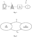
- Fig 1 is a schematic diagram illustrating a cellular network 8 where embodiments presented herein may be applied.
- the cellular network 8 comprises a core network 3 and one or more network nodes 1, here in the form of radio base stations being evolved Node Bs, also known as eNode Bs or eNBs.
- the network node 1 could also be in the form of Node Bs, BTSs (Base Transceiver Stations) and/or BSSs (Base Station Subsystems), etc.
- the network node 1 provides radio connectivity to a plurality of wireless devices 2.
- wireless device is also known as mobile communication terminal, user equipment (UE), mobile terminal, user terminal, user agent, wireless terminal, machine-to-machine devices etc., and can be, for example, what today are commonly known as a mobile phone or a tablet/laptop with wireless connectivity or fixed mounted terminal.
- UE user equipment
- user agent wireless terminal
- machine-to-machine devices etc.
- the cellular network 8 may e.g. comply with any one or a combination of LTE (Long Term Evolution), W-CDMA (Wideband Code Division Multiplex), EDGE (Enhanced Data Rates for GSM (Global System for Mobile communication) Evolution), GPRS (General Packet Radio Service), CDMA2000 (Code Division Multiple Access 2000), or any other current or future wireless network, such as LTE-Advanced, as long as the principles described hereinafter are applicable.
- LTE Long Term Evolution
- W-CDMA Wideband Code Division Multiplex
- EDGE Enhanced Data Rates for GSM (Global System for Mobile communication) Evolution
- GPRS General Packet Radio Service
- CDMA2000 Code Division Multiple Access 2000
- any other current or future wireless network such as LTE-Advanced, as long as the principles described hereinafter are applicable.
- Communication between the wireless device 2 and the network node 1 occurs over a wireless radio interface, where uplink (UL) communication occurs from the wireless device 2 to the network node 1 and downlink (DL) communication occurs from the network node 1 to the wireless device 2.
- UL uplink
- DL downlink
- the quality of the wireless radio interface to each wireless device 2 can vary over time and depends on the position of the wireless device 2, due to effects such as fading, interference, multipath propagation, etc.
- the network node 1 is also connected to the core network 3 for connectivity to central functions and a wide area network 7, such as the Internet.
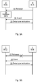
- Fig 2 is a state diagram illustrating states for VoIP for the wireless device of Fig 1 .
- the states are valid separately for the transmitter(s) for either one or both of uplink and downlink.
- VoIP is used in VoLTE, voice over LTE, whereby traffic is delivered using IP (Internet Protocol).
- IP Internet Protocol
- the transmitter is in the wireless device.
- the transmitter When voice is encoded by a voice encoder on the transmitter side, the transmitter is in a talk state 10. The speech is then encoded into packets with a typical periodicity of 20 ms. Due to the regularity and relative short periodicity of the talk state 10, it is beneficial for battery consumption of the wireless device not to need to transmit SRs, since this allows better usage of mechanisms such as Discontinuous Reception (DRX). This is achieved by activating uplink SPS for VoIP for the wireless device, by the network node allocating an UL SPS grant to the wireless device.
- DRX Discontinuous Reception
- the transmitter When there is silence, the transmitter is in a silence state 11. In this state, the voice encoder generates Silence Indication Descriptor (SID) frames that the receiver uses to generate comfort noise.
- SID frames have a much longer spacing than the speech frames, 160 ms compared to 20ms, and are also smaller ⁇ 400 bits compared to ⁇ 600 bits.
- the speech encoders may use voice activity detection in order to identify when there are talk spurts, triggering a transition 12 from the silence state 11 to the talk state 10, and when there is only silence, triggering a transition 13 from the talk state 10 to the silence state.
- the transition 13 from the talk state to the silence state can be a trigger to release the SPS for the wireless device.
- SPS would not be beneficial in silence state. If SPS would be used in silence state 11 (disabling the possibility for the wireless device to send SR) it would be necessary to keep track of the buffer status in the network node. In the silence state 11 the wireless device transmits SID packets once every 160 ms so the network node would update the buffer status with a SID packet once every 160 ms. If the wireless device switches to talk state 10, the wireless device would have to wait on average 80 ms to get a grant. The time budget is 80 ms, so the switch from silence to talk would cause severe packet delay and packet loss. Since the switches between the talk state 10 and silence state 11 occur often, such an issue would be very common.
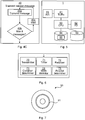
- Fig 3A-B are schematic signalling diagrams illustrating signalling for release of SPS between the network node 1 and the wireless device 2 of Fig 1 .
- SPS is particularly useful for periodic low volume traffic, such as for voice (e.g. using VoIP).
- voice e.g. using VoIP
- the dynamic scheduling of traditional LTE consumes a significant amount of overhead in comparison to the payload traffic.
- Figs 3A-B The signalling of Figs 3A-B occurs between the network node 1 and the wireless device 2.
- the network node 1 transmits an SPS release message 15 to the wireless device 2.
- the wireless device 16 acts upon this and releases SPS 16 as instructed.
- the network node 1 sends an uplink grant message 18 to the wireless device 2.
- the wireless device 2 responds by sending a data type indication 20.
- the data type indication 20 can include a buffer status report (BSR).
- BSR buffer status report
- the data type indication 20 includes payload data transmitted at this time if there is any uplink data in the uplink buffer of the wireless device 2.
- Fig 3B is similar to Fig 3A but instead illustrates a fault scenario.
- the SPS release request message 15 is not correctly received by the wireless device, indicated by the cross on this message transmission.
- the reason for the incorrect reception may e.g. be due to non-ideal radio conditions, such as fading, interference, etc. In this case, there is no release of the SPS.
- the wireless device responds with the data type indication 20.
- the data type indication 20 can include a BSR and/ or payload data.
- Figs 4A-C are flow charts illustrating embodiments of methods performed in the network node of Fig 1 for releasing SPS. The method is performed for one wireless device and may optionally be performed in parallel for a plurality of wireless devices. First, the method of an embodiment of Fig 4A will be described.
- an SPS release message is transmitted to the wireless device to release uplink SPS.
- the SPS release message can e.g. be PDCCH (Physical Dedicated Control Channel) message as defined in 3GPP TS 36.213 V10.3.0 Table 9.2-1A.
- a start timer step 41 a timer is started.
- conditional 1 st condition true step 43 it is determined whether a first condition is true.
- the first condition is true when the timer expires and/or a scheduling request has been received from the wireless device.
- the method continues to a transmit grant step 44. Otherwise, the method re-executes the conditional 1 st condition true step, optionally after an idle period (not shown).
- a grant for uplink transmission is transmitted to the wireless device.
- the transmission of the grant is performed to trigger the wireless device to send the data type indication buffer status report.
- One reason for transmitting the grant is to allow the wireless device to transmit uplink data, even if no transmitted SPS release message was correctly received by the wireless device.
- the method waits in order to perform the transmit grant step 44 at a configurable time after the transmit release message step 40.
- a data type indication is received from the wireless device.
- the data type indication can, for instance, include the BSR and/or payload data.
- the BSR indicates the state of the uplink buffer of the wireless device.
- the BSR allows the type of data in the buffer, e.g. VoIP data and/or other (not VoIP) data to be identified.
- the payload data itself can alternatively or additionally be analysed to determine whether there is only VoIP data transmitted and/or other (nor VoIP) data transmitted, by examining headers of the payload data of the actual data using e.g. deep packet inspection.
- the BSR can be used by itself to determine whether there is only VoIP data.
- the payload data can be used to determine whether there is only VoIP data, or both the BSR and the payload data can be used to determine whether there is only VoIP data.
- a conditional release message received step 46 it is determined that the SPS release message has been received by the wireless device when a scheduling request has been received from the wireless device and the data type indication indicates only VoIP data from the wireless device. Since, in such a case, there is only VoIP data , it is clear that the VoIP data is the cause of the scheduling request. Moreover, if the SPS release message would not have been received correctly, the wireless device would still be in SPS for uplink VoIP transmissions and would thus refrain from sending any scheduling requests to send the VoIP uplink data. Consequently, the combination of only VoIP data and the presence of the scheduling requests implies that SPS has been released in the wireless device.
- Implicit verification can e.g. be that the release message received step 46 only executes after a grant has been transmitted, as exemplified in Fig 4A (and also Fig 4B ).
- Explicit verification can e.g. be that the grant transmission (either as the grant itself or an indication of the grant) is saved in a memory which can be checked in this step.
- the method ends. Otherwise, the determination of if the release message has been correctly received is uncertain and the method returns to the transmit release message step 40 to send a new SPS release message.
- the network node can, in at least some cases, determine when the SPS release message was correctly received by the wireless device without introducing any new signalling. As explained above, any increase in accuracy of such determination is of great significance. Hence, even if this method is not able to determine conclusively in all cases whether the SPS release message was correctly received or not, it is still of great use.
- Fig 4B illustrates a method for releasing SPS according to one embodiment. This method is similar to the method illustrated in Fig 4A , and only new or modified steps, compared to the method of Fig 4A , will be described.
- the network node detects that uplink VoIP communication from the wireless device transitions from a talk state to a silence state (see Fig 2 ).
- no release message received step 48 it is determined that no SPS release message has been received when no scheduling request has been received from the wireless device and the data type indication indicates only VoIP data from the wireless device.
- the wireless device refrains from sending any scheduling requests for the VoIP data. But other uplink data is not restricted by SPS, whereby any presence of other (not VoIP) data would cause the wireless device to send a scheduling request. Consequently, the combination of only VoIP data and the absence scheduling requests implies that SPS is still active and thus the SPS release message has not been correctly received in the wireless device.
- the method returns to the transmit release message step 40 to send a new SPS release message.
- the result of this step is false, it is unsure whether the SPS release message has been received by the wireless device and the method returns to the start timer step 41.
- Table 1 truth table illustrating the determination of whether the SPS release message has been correctly received by the wireless device SR received No SR received Only VoIP True False Not only VoIP Uncertain Uncertain
- the method returns to the start timer step 41 when the data type indication (e.g. BSR and/or payload data) indicates that there is not only VoIP data from the wireless device or part.
- the data type indication e.g. BSR and/or payload data
- Fig 4C is a flow chart illustrating details of the transmit release message step 40 of Figs 4A-B according to one embodiment.
- a transmit message step 40a the SPS release message is transmitted to the wireless device.
- a conditional max # of messages step 40b it is determined whether a maximum number of messages has been transmitted. If this is true, then the transmit release message step 40 ends. Otherwise, the method proceeds to a wait step 40c.
- the method waits a certain amount of time. This waiting is performed between successive executions of the transmit message step 40a, creating time diversity of the transmissions of the SPS release messages.
- the transmit release message step 40 is performed in parallel to the other steps of Figs 4A-B .
- the time of the wait step 40c and the maximum number of messages of the conditional max # of messages step 40b are parameters which are optionally configurable.
- the probability for correct decoding of at least one of the SPS release messages is increased.
- Fig 5 is a schematic diagram showing some components of the network node 1 of Fig 1 .
- a processor 60 is provided using any combination of one or more of a suitable central processing unit (CPU), multiprocessor, microcontroller, digital signal processor (DSP), application specific integrated circuit etc., capable of executing software instructions 66 stored in a memory 64, which can thus be a computer program product.
- the processor 60 can be configured to execute the methods described with reference to Figs 4A-C above.
- the memory 64 can be any combination of read and write memory (RAM) and read only memory (ROM).
- the memory 64 also comprises persistent storage, which, for example, can be any single one or combination of magnetic memory, optical memory, solid state memory or even remotely mounted memory.
- a data memory 63 is also provided for reading and/or storing data during execution of software instructions in the processor 60.
- the data memory 63 can be any combination of read and write memory (RAM) and read only memory (ROM).
- the network node 1 further comprises an I/O interface 62 for communicating with other external entities.
- the I/O interface 62 also includes a user interface.
- the network node 1 also comprises one or more transceivers 61, comprising analogue and digital components, and a suitable number of antennas 65 for wireless communication with wireless devices as shown in Fig 1 .
- Fig 6 is a schematic diagram showing functional modules of the network node 1 of Figs 1 and 5 .
- the modules can be implemented using software instructions such as a computer program executing in the network node 1 and/or using hardware, such as application specific integrated circuits, field programmable gate arrays, discrete logical components, etc.
- the modules correspond to the steps in the methods illustrated in Figs 4A-C .
- a transmitter 70 is arranged to transmit SPS release messages and grants. This module corresponds to the transmit release message step 40 and the transmit grant step 44 of Figs 4A-C .
- a timer 71 is arranged to keep track of a time to see if it has expired or not.
- the timer can e.g. be a positive timer, starting at zero and increasing with time to expire when a certain time has passed.
- the timer can be a negative timer, starting at a certain time and decreasing with time to expire when it reaches zero.
- This module corresponds to the start timer step 41 of Figs 4A-B .
- a receiver 72 is arranged to receive the data type indication from the wireless device. This module corresponds to the receive data type indication step 45 of Figs 4A-B .
- a condition determiner 73 is arranged to determine whether the first condition is true. This module corresponds to the conditional 1 st condition true step 43 of Figs 4A-B .
- a state detector 74 is arranged to detect the VoIP state of the wireless device in question. This module corresponds to the detect talk -> silence step 39 of Fig 4B .
- a receipt determiner 75 is arranged to determine whether the SPS release message was received by the wireless device. This module corresponds to the release message received step 46 of Figs 4A-B and the no release message received step 48 of Fig 4B .
- Fig 7 shows one example of a computer program product 90 comprising computer readable means.
- a computer program 91 can be stored, which computer program can cause a processor to execute a method according to embodiments described herein.
- the computer program product is an optical disc, such as a CD (compact disc) or a DVD (digital versatile disc) or a Blu-Ray disc.
- the computer program product could also be embodied in a memory of a device, such as the computer program product 64 of Fig 5 .
- the computer program 91 is here schematically shown as a track on the depicted optical disk, the computer program can be stored in any way which is suitable for the computer program product, such as a removable solid state memory.
Landscapes
- Engineering & Computer Science (AREA)
- Computer Networks & Wireless Communication (AREA)
- Signal Processing (AREA)
- Mobile Radio Communication Systems (AREA)
Claims (17)
- Verfahren zum Freigeben von semipersistenter Planung, SPS, für eine Drahtlosvorrichtung (2), wobei die semipersistente Planung für Voice-over-Internet-Protocol (VoIP) verwendet wurde, wobei das Verfahren in einem Netzknoten (1) durchgeführt wird und die folgenden Schritte umfasst:Übertragen (40) einer SPS-Freigabenachricht an die Drahtlosvorrichtung (2), um Uplink-SPS freizugeben;Starten (41) eines Timers;wenn eine erste Bedingung erfüllt ist, Übertragen (44) einer Gewährung für Uplink-Übertragung an die Drahtlosvorrichtung (2), wobei die erste Bedingung erfüllt ist, wenn der Timer abläuft und/oder eine Planungsaufforderung von der Drahtlosvorrichtung (2) empfangen wurde;Empfangen (45) einer Datentypangabe von der Drahtlosvorrichtung (2); undBestimmen (46), dass eine SPS-Freigabenachricht korrekt durch die Drahtlosvorrichtung (2) empfangen wurde, wenn eine Planungsaufforderung von der Drahtlosvorrichtung (2) empfangen wurde, die Gewährung übertragen wurde und die Datentypangabe nur VoIP-Daten von der Drahtlosvorrichtung angibt.
- Verfahren nach Anspruch 1, wobei die Datentypangabe einen Pufferstatusbericht umfasst und/oder wobei die Datentypangabe Nutzdaten umfasst.
- Verfahren nach einem der vorstehenden Ansprüche, ferner umfassend den folgenden Schritt:
Bestimmen (48), dass keine SPS-Freigabenachricht korrekt durch die Drahtlosvorrichtung (2) empfangen wurde, wenn keine Planungsaufforderung von der Drahtlosvorrichtung (2) empfangen wurde und die Datentypangabe nur VoIP-Daten von der Drahtlosvorrichtung (2) angibt. - Verfahren nach Anspruch 4, wobei das Verfahren wiederholt wird, wenn bestimmt wird, dass keine SPS-Freigabenachricht korrekt empfangen wurde.
- Verfahren nach einem der vorstehenden Ansprüche, ferner umfassend den folgenden Schritt:
Zurückkehren zu dem Schritt des Startens (41) eines Timers, wenn eine Planungsaufforderung von der Drahtlosvorrichtung (2) empfangen wurde und die Datentypangabe nicht nur VoIP-Daten von der Drahtlosvorrichtung (2) angibt. - Verfahren nach einem der vorstehenden Ansprüche, wobei der Schritt des Übertragens (40) einer SPS-Freigabenachricht wiederholt wird.
- Verfahren nach Anspruch 7, wobei die Wiederholung des Übertragens (40) einer SPS-Freigabenachricht parallel zu anderen Schritten des Verfahrens durchgeführt wird.
- Verfahren nach einem der vorstehenden Ansprüche, wobei der Schritt des Übertragens (44) einer Gewährung auslöst, dass die Drahtlosvorrichtung (2) die Datentypangabe sendet.
- Verfahren nach einem der vorstehenden Ansprüche, ferner umfassend den folgenden Schritt vor dem Schritt des Übertragens (40) einer SPS-Freigabenachricht:
Erkennen (39), dass Uplink-VoIP-Kommunikation von der Drahtlosvorrichtung (2) aus einem Sprechzustand in einen Ruhezustand übergeht. - Netzknoten (1), der dazu angeordnet ist, semipersistente Planung, SPS, für eine Drahtlosvorrichtung (2) freizugeben, wobei die semipersistente Planung für Voice-over-Internet-Protocol (VoIP) verwendet wurde, wobei der Netzknoten (1) Folgendes umfasst:einen Prozessor (60); undeinen Speicher (64), der Anweisungen (66) speichert, die bei Ausführung durch den Prozessor den Netzknoten (1) zu Folgendem veranlassen:eine SPS-Freigabenachricht an die Drahtlosvorrichtung (2) zu übertragen, um Uplink-SPS freizugeben;einen Timer zu starten;wenn eine erste Bedingung erfüllt ist, eine Gewährung für Uplink-Übertragung an die Drahtlosvorrichtung (2) zu übertragen, wobei die erste Bedingung erfüllt ist, wenn der Timer abläuft und/oder eine Planungsaufforderung von der Drahtlosvorrichtung (2) empfangen wurde;eine Datentypangabe von der Drahtlosvorrichtung (2) zu empfangen; undzu bestimmen, dass eine SPS-Freigabenachricht korrekt durch die Drahtlosvorrichtung (2) empfangen wurde, wenn eine Planungsaufforderung von der Drahtlosvorrichtung (2) empfangen wurde, die Gewährung übertragen wurde und die Datentypangabe nur VoIP-Daten von der Drahtlosvorrichtung angibt.
- Netzknoten (1) nach Anspruch 11, wobei die Datentypangabe einen Pufferstatusbericht umfasst und/oder wobei die Datentypangabe Nutzdaten umfasst.
- Netzknoten (1) nach einem der Ansprüche 11 bis 13, ferner umfassend Anweisungen, die bei Ausführung durch den Prozessor den Netzknoten (1) dazu veranlassen, zu bestimmen, dass keine SPS-Freigabenachricht korrekt durch die Drahtlosvorrichtung (2) empfangen wurde, wenn keine Planungsaufforderung von der Drahtlosvorrichtung (2) empfangen wurde und die Datentypangabe nur VoIP-Daten von der Drahtlosvorrichtung (2) angibt.
- Netzknoten (1) nach Anspruch 14, ferner umfassend Anweisungen, die bei Ausführung durch den Prozessor den Netzknoten (1) dazu veranlassen, die Anweisungen zu wiederholen, wenn bestimmt wird, dass keine SPS-Freigabenachricht korrekt empfangen wurde.
- Netzknoten (1) nach einem der Ansprüche 11 bis 15, ferner umfassend Anweisungen, die bei Ausführung durch den Prozessor den Netzknoten (1) dazu veranlassen, zu den Anweisungen, einen Timer zu starten, zurückzukehren, wenn eine Planungsaufforderung von der Drahtlosvorrichtung (2) empfangen wurde und die Datentypangabe nicht nur VoIP-Daten von der Drahtlosvorrichtung (2) angibt.
- Netzknoten (1) nach einem der Ansprüche 11 bis 16, ferner umfassend Anweisungen, die bei Ausführung durch den Prozessor den Netzknoten (1) dazu veranlassen, die Anweisungen zu wiederholen, um eine SPS-Freigabenachricht zu wiederholen.
- Netzknoten (1) nach Anspruch 17, wobei die Anweisungen, eine SPS-Freigabenachricht wiederholt zu übertragen, parallel zu anderen Anweisungen durchgeführt werden.
- Netzknoten (1) nach einem der Ansprüche 11 bis 18, ferner umfassend Anweisungen, die bei Ausführung durch den Prozessor den Netzknoten (1) dazu veranlassen, zu erkennen, dass Uplink-VoIP-Kommunikation von der Drahtlosvorrichtung (2) aus einem Sprechzustand in einen Ruhezustand übergeht.
Applications Claiming Priority (1)
| Application Number | Priority Date | Filing Date | Title |
|---|---|---|---|
| PCT/SE2014/050079 WO2015112063A1 (en) | 2014-01-23 | 2014-01-23 | Release of semi-persistent scheduling |
Publications (2)
| Publication Number | Publication Date |
|---|---|
| EP3097733A1 EP3097733A1 (de) | 2016-11-30 |
| EP3097733B1 true EP3097733B1 (de) | 2018-05-30 |
Family
ID=50113010
Family Applications (1)
| Application Number | Title | Priority Date | Filing Date |
|---|---|---|---|
| EP14704707.0A Active EP3097733B1 (de) | 2014-01-23 | 2014-01-23 | Freigabe von semipersistenter planung |
Country Status (4)
| Country | Link |
|---|---|
| US (1) | US10349439B2 (de) |
| EP (1) | EP3097733B1 (de) |
| CN (1) | CN105934990B (de) |
| WO (1) | WO2015112063A1 (de) |
Families Citing this family (12)
| Publication number | Priority date | Publication date | Assignee | Title |
|---|---|---|---|---|
| KR102275354B1 (ko) * | 2014-02-17 | 2021-07-09 | 삼성전자 주식회사 | 기지국 및 기지국의 단말 연결 관리 방법 |
| US10299284B2 (en) * | 2015-08-31 | 2019-05-21 | Qualcomm, Incorporated | Inter-access terminal unblocking and enhanced contention for co-existence on a shared communication medium |
| US10218474B2 (en) * | 2015-09-02 | 2019-02-26 | Htc Corporation | Device and method of handling scheduling request transmission |
| EP3343994B1 (de) * | 2015-09-25 | 2020-08-12 | Huawei Technologies Co., Ltd. | Dienstverarbeitungsverfahren und -vorrichtung |
| US10715302B2 (en) | 2015-10-14 | 2020-07-14 | Wilson Electronics, Llc | Channelization for signal boosters |
| CN108292948A (zh) * | 2015-10-14 | 2018-07-17 | 威尔逊电子有限责任公司 | 信号增强器的信道化 |
| US10129806B2 (en) * | 2016-03-10 | 2018-11-13 | At&T Mobility Ii Llc | Method to assign IP traffic to desired network elements based on packet or service type |
| US10200910B1 (en) * | 2016-10-31 | 2019-02-05 | Sprint Communications Company L.P. | Wireless communication system to dynamically modify a buffer status report (BSR) timer in a wireless relay |
| CN110326354B (zh) * | 2017-04-26 | 2023-11-24 | Oppo广东移动通信有限公司 | 资源调度的方法和设备 |
| WO2019090720A1 (zh) * | 2017-11-10 | 2019-05-16 | Oppo广东移动通信有限公司 | 传输数据的方法和设备 |
| US11026289B2 (en) * | 2018-12-27 | 2021-06-01 | Industrial Technology Research Institute | Base station and resource allocation method based on semi-persistent scheduling |
| TWI701963B (zh) * | 2018-12-27 | 2020-08-11 | 財團法人工業技術研究院 | 基地台及其基於半永久性排程的資源分配方法 |
Family Cites Families (18)
| Publication number | Priority date | Publication date | Assignee | Title |
|---|---|---|---|---|
| EP2346297B1 (de) * | 2007-12-14 | 2014-09-24 | BlackBerry Limited | System und Verfahren zum Planen von Betriebsmittelanforderungen |
| CN101572913A (zh) * | 2008-04-28 | 2009-11-04 | 华为技术有限公司 | 缓冲区状态报告的处理方法及装置 |
| DE202009018265U1 (de) * | 2008-11-04 | 2011-08-26 | Htc Corporation | System und Vorrichtung zur Verbesserung eines Ressourcenfreigabeprozesses bei der semi-persistenten Terminierung in einem drahtlosen Kommunikationssystem |
| JP2012512613A (ja) * | 2008-12-17 | 2012-05-31 | モトローラ モビリティ インコーポレイテッド | 無線通信デバイスによる半永久的なリソースの解放 |
| WO2010088680A1 (en) * | 2009-02-02 | 2010-08-05 | Research In Motion Limited | Indication of uplink semi-persistent scheduling explicit release using a downlink physical downlink control channel |
| US8295253B2 (en) * | 2009-02-05 | 2012-10-23 | Qualcomm Incorporated | Efficient ACK transmission for uplink semi-persistent scheduling release in LTE |
| CN101835271A (zh) | 2009-03-12 | 2010-09-15 | 华为技术有限公司 | 一种资源释放和分配的方法、装置及网络设备 |
| US9647741B2 (en) | 2009-07-31 | 2017-05-09 | Qualcomm Incorporated | Physical uplink control channel (PUCCH) resource mapping with transmit diversity |
| US8743859B2 (en) * | 2009-08-06 | 2014-06-03 | Via Telecom Co., Ltd. | Apparatuses, systems, and methods for managing operation status of wireless transmissions and receptions |
| CN102474886B (zh) * | 2009-08-12 | 2014-11-19 | 交互数字专利控股公司 | 基于争用的上行链路数据传输方法和设备 |
| KR101838070B1 (ko) | 2010-09-30 | 2018-04-26 | 엘지전자 주식회사 | 제어 정보를 전송하는 방법 및 이를 위한 장치 |
| JP5747990B2 (ja) * | 2011-09-14 | 2015-07-15 | 富士通株式会社 | 無線端末および基地局 |
| CN103875298B (zh) * | 2011-10-04 | 2018-04-20 | 瑞典爱立信有限公司 | 通信基站的调度 |
| WO2014003327A1 (en) * | 2012-06-26 | 2014-01-03 | Lg Electronics Inc. | Method and apparatus for cancelling buffer status report in wireless communication system |
| US20150009874A1 (en) * | 2013-07-08 | 2015-01-08 | Amazon Technologies, Inc. | Techniques for optimizing propagation of multiple types of data |
| EP3195689B1 (de) * | 2014-09-19 | 2019-02-06 | Telefonaktiebolaget LM Ericsson (publ) | Verfahren zur uplink-sps-freisetzung |
| ES2945339T3 (es) * | 2015-09-18 | 2023-06-30 | Guangdong Oppo Mobile Telecommunications Corp Ltd | Dispositivo terminal, dispositivo de estación base, método de comunicación y circuito integrado |
| CN105429736B (zh) * | 2015-11-02 | 2020-01-07 | 电信科学技术研究院 | 一种发送和接收反馈的方法及设备 |
-
2014
- 2014-01-23 EP EP14704707.0A patent/EP3097733B1/de active Active
- 2014-01-23 US US15/107,350 patent/US10349439B2/en active Active
- 2014-01-23 CN CN201480073955.8A patent/CN105934990B/zh not_active Expired - Fee Related
- 2014-01-23 WO PCT/SE2014/050079 patent/WO2015112063A1/en not_active Ceased
Non-Patent Citations (1)
| Title |
|---|
| None * |
Also Published As
| Publication number | Publication date |
|---|---|
| US20170027018A1 (en) | 2017-01-26 |
| EP3097733A1 (de) | 2016-11-30 |
| CN105934990B (zh) | 2019-07-09 |
| CN105934990A (zh) | 2016-09-07 |
| WO2015112063A1 (en) | 2015-07-30 |
| US10349439B2 (en) | 2019-07-09 |
Similar Documents
| Publication | Publication Date | Title |
|---|---|---|
| EP3097733B1 (de) | Freigabe von semipersistenter planung | |
| KR102429350B1 (ko) | Lte-u에서의 매체 접근 제어 | |
| JP6096775B2 (ja) | 不連続受信(drx)と共に構成されるユーザ機器のアクティブ時間ステータスに基づくアップリンク制御シグナリングを送信すべきかの決定 | |
| TWI488526B (zh) | 無線通信系統中的方法及配置 | |
| US8805387B2 (en) | Method and apparatus to control scheduling | |
| US10009909B2 (en) | Changing semi-persistent scheduling interval | |
| US20150305084A1 (en) | Transmission control method, transmission method, and device | |
| US9564997B2 (en) | Method and apparatus for flushing uplink HARQ buffer in C-DRX mode | |
| US20150195854A1 (en) | Methods and apparatus for contention based transmission | |
| EP3387769B1 (de) | Funknetzknoten und drahtlose vorrichtung sowie verfahren darin | |
| US20150351153A1 (en) | Enhanced physical harq indicator channel decoding | |
| US20150341938A1 (en) | Uplink operation for rlc communications | |
| US10492176B2 (en) | Methods, network node, wireless device, computer programs and computer program products for use with discontinuous reception | |
| US9930699B2 (en) | Providing access control parameters to a user equipment | |
| EP2959744B1 (de) | Verfahren, drahtlose vorrichtung und computerprogramm zur verwendung mit diskontinuierlichem empfang | |
| EP3498011B1 (de) | Ul-terminplanungs-timing in tdd mit 1-ms-tti und reduzierter verarbeitungszeit | |
| CN111343665B (zh) | 用于基于竞争的上行链路传输的解码的方法和节点 | |
| WO2017028883A1 (en) | Latency enhancement in discontinuous reception scenarios | |
| KR101747121B1 (ko) | 리소스 할당 방법 및 기지국 | |
| EP3446423B1 (de) | Anwendung eines robusteren übertragungsverfahrens | |
| WO2014043892A1 (en) | Collision handling for contention based uplink transmission |
Legal Events
| Date | Code | Title | Description |
|---|---|---|---|
| PUAI | Public reference made under article 153(3) epc to a published international application that has entered the european phase |
Free format text: ORIGINAL CODE: 0009012 |
|
| 17P | Request for examination filed |
Effective date: 20160620 |
|
| AK | Designated contracting states |
Kind code of ref document: A1 Designated state(s): AL AT BE BG CH CY CZ DE DK EE ES FI FR GB GR HR HU IE IS IT LI LT LU LV MC MK MT NL NO PL PT RO RS SE SI SK SM TR |
|
| AX | Request for extension of the european patent |
Extension state: BA ME |
|
| DAX | Request for extension of the european patent (deleted) | ||
| GRAP | Despatch of communication of intention to grant a patent |
Free format text: ORIGINAL CODE: EPIDOSNIGR1 |
|
| STAA | Information on the status of an ep patent application or granted ep patent |
Free format text: STATUS: GRANT OF PATENT IS INTENDED |
|
| RIC1 | Information provided on ipc code assigned before grant |
Ipc: H04W 72/12 20090101ALN20180313BHEP Ipc: H04W 72/04 20090101AFI20180313BHEP |
|
| GRAS | Grant fee paid |
Free format text: ORIGINAL CODE: EPIDOSNIGR3 |
|
| INTG | Intention to grant announced |
Effective date: 20180328 |
|
| RIC1 | Information provided on ipc code assigned before grant |
Ipc: H04W 72/12 20090101ALN20180320BHEP Ipc: H04W 72/04 20090101AFI20180320BHEP |
|
| GRAA | (expected) grant |
Free format text: ORIGINAL CODE: 0009210 |
|
| STAA | Information on the status of an ep patent application or granted ep patent |
Free format text: STATUS: THE PATENT HAS BEEN GRANTED |
|
| AK | Designated contracting states |
Kind code of ref document: B1 Designated state(s): AL AT BE BG CH CY CZ DE DK EE ES FI FR GB GR HR HU IE IS IT LI LT LU LV MC MK MT NL NO PL PT RO RS SE SI SK SM TR |
|
| REG | Reference to a national code |
Ref country code: GB Ref legal event code: FG4D |
|
| REG | Reference to a national code |
Ref country code: CH Ref legal event code: EP |
|
| REG | Reference to a national code |
Ref country code: AT Ref legal event code: REF Ref document number: 1004969 Country of ref document: AT Kind code of ref document: T Effective date: 20180615 |
|
| REG | Reference to a national code |
Ref country code: IE Ref legal event code: FG4D |
|
| REG | Reference to a national code |
Ref country code: DE Ref legal event code: R096 Ref document number: 602014026149 Country of ref document: DE |
|
| REG | Reference to a national code |
Ref country code: NL Ref legal event code: FP |
|
| REG | Reference to a national code |
Ref country code: LT Ref legal event code: MG4D |
|
| PG25 | Lapsed in a contracting state [announced via postgrant information from national office to epo] |
Ref country code: SE Free format text: LAPSE BECAUSE OF FAILURE TO SUBMIT A TRANSLATION OF THE DESCRIPTION OR TO PAY THE FEE WITHIN THE PRESCRIBED TIME-LIMIT Effective date: 20180530 Ref country code: LT Free format text: LAPSE BECAUSE OF FAILURE TO SUBMIT A TRANSLATION OF THE DESCRIPTION OR TO PAY THE FEE WITHIN THE PRESCRIBED TIME-LIMIT Effective date: 20180530 Ref country code: ES Free format text: LAPSE BECAUSE OF FAILURE TO SUBMIT A TRANSLATION OF THE DESCRIPTION OR TO PAY THE FEE WITHIN THE PRESCRIBED TIME-LIMIT Effective date: 20180530 Ref country code: NO Free format text: LAPSE BECAUSE OF FAILURE TO SUBMIT A TRANSLATION OF THE DESCRIPTION OR TO PAY THE FEE WITHIN THE PRESCRIBED TIME-LIMIT Effective date: 20180830 Ref country code: FI Free format text: LAPSE BECAUSE OF FAILURE TO SUBMIT A TRANSLATION OF THE DESCRIPTION OR TO PAY THE FEE WITHIN THE PRESCRIBED TIME-LIMIT Effective date: 20180530 Ref country code: CY Free format text: LAPSE BECAUSE OF FAILURE TO SUBMIT A TRANSLATION OF THE DESCRIPTION OR TO PAY THE FEE WITHIN THE PRESCRIBED TIME-LIMIT Effective date: 20180530 Ref country code: BG Free format text: LAPSE BECAUSE OF FAILURE TO SUBMIT A TRANSLATION OF THE DESCRIPTION OR TO PAY THE FEE WITHIN THE PRESCRIBED TIME-LIMIT Effective date: 20180830 |
|
| PG25 | Lapsed in a contracting state [announced via postgrant information from national office to epo] |
Ref country code: GR Free format text: LAPSE BECAUSE OF FAILURE TO SUBMIT A TRANSLATION OF THE DESCRIPTION OR TO PAY THE FEE WITHIN THE PRESCRIBED TIME-LIMIT Effective date: 20180831 Ref country code: RS Free format text: LAPSE BECAUSE OF FAILURE TO SUBMIT A TRANSLATION OF THE DESCRIPTION OR TO PAY THE FEE WITHIN THE PRESCRIBED TIME-LIMIT Effective date: 20180530 Ref country code: LV Free format text: LAPSE BECAUSE OF FAILURE TO SUBMIT A TRANSLATION OF THE DESCRIPTION OR TO PAY THE FEE WITHIN THE PRESCRIBED TIME-LIMIT Effective date: 20180530 Ref country code: HR Free format text: LAPSE BECAUSE OF FAILURE TO SUBMIT A TRANSLATION OF THE DESCRIPTION OR TO PAY THE FEE WITHIN THE PRESCRIBED TIME-LIMIT Effective date: 20180530 |
|
| REG | Reference to a national code |
Ref country code: AT Ref legal event code: MK05 Ref document number: 1004969 Country of ref document: AT Kind code of ref document: T Effective date: 20180530 |
|
| PG25 | Lapsed in a contracting state [announced via postgrant information from national office to epo] |
Ref country code: CZ Free format text: LAPSE BECAUSE OF FAILURE TO SUBMIT A TRANSLATION OF THE DESCRIPTION OR TO PAY THE FEE WITHIN THE PRESCRIBED TIME-LIMIT Effective date: 20180530 Ref country code: SK Free format text: LAPSE BECAUSE OF FAILURE TO SUBMIT A TRANSLATION OF THE DESCRIPTION OR TO PAY THE FEE WITHIN THE PRESCRIBED TIME-LIMIT Effective date: 20180530 Ref country code: DK Free format text: LAPSE BECAUSE OF FAILURE TO SUBMIT A TRANSLATION OF THE DESCRIPTION OR TO PAY THE FEE WITHIN THE PRESCRIBED TIME-LIMIT Effective date: 20180530 Ref country code: AT Free format text: LAPSE BECAUSE OF FAILURE TO SUBMIT A TRANSLATION OF THE DESCRIPTION OR TO PAY THE FEE WITHIN THE PRESCRIBED TIME-LIMIT Effective date: 20180530 Ref country code: EE Free format text: LAPSE BECAUSE OF FAILURE TO SUBMIT A TRANSLATION OF THE DESCRIPTION OR TO PAY THE FEE WITHIN THE PRESCRIBED TIME-LIMIT Effective date: 20180530 Ref country code: PL Free format text: LAPSE BECAUSE OF FAILURE TO SUBMIT A TRANSLATION OF THE DESCRIPTION OR TO PAY THE FEE WITHIN THE PRESCRIBED TIME-LIMIT Effective date: 20180530 Ref country code: RO Free format text: LAPSE BECAUSE OF FAILURE TO SUBMIT A TRANSLATION OF THE DESCRIPTION OR TO PAY THE FEE WITHIN THE PRESCRIBED TIME-LIMIT Effective date: 20180530 |
|
| PG25 | Lapsed in a contracting state [announced via postgrant information from national office to epo] |
Ref country code: IT Free format text: LAPSE BECAUSE OF FAILURE TO SUBMIT A TRANSLATION OF THE DESCRIPTION OR TO PAY THE FEE WITHIN THE PRESCRIBED TIME-LIMIT Effective date: 20180530 Ref country code: SM Free format text: LAPSE BECAUSE OF FAILURE TO SUBMIT A TRANSLATION OF THE DESCRIPTION OR TO PAY THE FEE WITHIN THE PRESCRIBED TIME-LIMIT Effective date: 20180530 |
|
| REG | Reference to a national code |
Ref country code: DE Ref legal event code: R097 Ref document number: 602014026149 Country of ref document: DE |
|
| PLBE | No opposition filed within time limit |
Free format text: ORIGINAL CODE: 0009261 |
|
| STAA | Information on the status of an ep patent application or granted ep patent |
Free format text: STATUS: NO OPPOSITION FILED WITHIN TIME LIMIT |
|
| 26N | No opposition filed |
Effective date: 20190301 |
|
| PG25 | Lapsed in a contracting state [announced via postgrant information from national office to epo] |
Ref country code: SI Free format text: LAPSE BECAUSE OF FAILURE TO SUBMIT A TRANSLATION OF THE DESCRIPTION OR TO PAY THE FEE WITHIN THE PRESCRIBED TIME-LIMIT Effective date: 20180530 |
|
| PG25 | Lapsed in a contracting state [announced via postgrant information from national office to epo] |
Ref country code: MC Free format text: LAPSE BECAUSE OF FAILURE TO SUBMIT A TRANSLATION OF THE DESCRIPTION OR TO PAY THE FEE WITHIN THE PRESCRIBED TIME-LIMIT Effective date: 20180530 |
|
| REG | Reference to a national code |
Ref country code: CH Ref legal event code: PL |
|
| PG25 | Lapsed in a contracting state [announced via postgrant information from national office to epo] |
Ref country code: LU Free format text: LAPSE BECAUSE OF NON-PAYMENT OF DUE FEES Effective date: 20190123 |
|
| REG | Reference to a national code |
Ref country code: BE Ref legal event code: MM Effective date: 20190131 |
|
| REG | Reference to a national code |
Ref country code: IE Ref legal event code: MM4A |
|
| PG25 | Lapsed in a contracting state [announced via postgrant information from national office to epo] |
Ref country code: FR Free format text: LAPSE BECAUSE OF NON-PAYMENT OF DUE FEES Effective date: 20190131 |
|
| PG25 | Lapsed in a contracting state [announced via postgrant information from national office to epo] |
Ref country code: BE Free format text: LAPSE BECAUSE OF NON-PAYMENT OF DUE FEES Effective date: 20190131 Ref country code: AL Free format text: LAPSE BECAUSE OF FAILURE TO SUBMIT A TRANSLATION OF THE DESCRIPTION OR TO PAY THE FEE WITHIN THE PRESCRIBED TIME-LIMIT Effective date: 20180530 |
|
| PG25 | Lapsed in a contracting state [announced via postgrant information from national office to epo] |
Ref country code: CH Free format text: LAPSE BECAUSE OF NON-PAYMENT OF DUE FEES Effective date: 20190131 Ref country code: LI Free format text: LAPSE BECAUSE OF NON-PAYMENT OF DUE FEES Effective date: 20190131 |
|
| PG25 | Lapsed in a contracting state [announced via postgrant information from national office to epo] |
Ref country code: IE Free format text: LAPSE BECAUSE OF NON-PAYMENT OF DUE FEES Effective date: 20190123 |
|
| PG25 | Lapsed in a contracting state [announced via postgrant information from national office to epo] |
Ref country code: TR Free format text: LAPSE BECAUSE OF FAILURE TO SUBMIT A TRANSLATION OF THE DESCRIPTION OR TO PAY THE FEE WITHIN THE PRESCRIBED TIME-LIMIT Effective date: 20180530 |
|
| PG25 | Lapsed in a contracting state [announced via postgrant information from national office to epo] |
Ref country code: MT Free format text: LAPSE BECAUSE OF NON-PAYMENT OF DUE FEES Effective date: 20190123 Ref country code: PT Free format text: LAPSE BECAUSE OF FAILURE TO SUBMIT A TRANSLATION OF THE DESCRIPTION OR TO PAY THE FEE WITHIN THE PRESCRIBED TIME-LIMIT Effective date: 20181001 |
|
| PG25 | Lapsed in a contracting state [announced via postgrant information from national office to epo] |
Ref country code: IS Free format text: LAPSE BECAUSE OF FAILURE TO SUBMIT A TRANSLATION OF THE DESCRIPTION OR TO PAY THE FEE WITHIN THE PRESCRIBED TIME-LIMIT Effective date: 20180930 |
|
| PG25 | Lapsed in a contracting state [announced via postgrant information from national office to epo] |
Ref country code: HU Free format text: LAPSE BECAUSE OF FAILURE TO SUBMIT A TRANSLATION OF THE DESCRIPTION OR TO PAY THE FEE WITHIN THE PRESCRIBED TIME-LIMIT; INVALID AB INITIO Effective date: 20140123 |
|
| PG25 | Lapsed in a contracting state [announced via postgrant information from national office to epo] |
Ref country code: MK Free format text: LAPSE BECAUSE OF FAILURE TO SUBMIT A TRANSLATION OF THE DESCRIPTION OR TO PAY THE FEE WITHIN THE PRESCRIBED TIME-LIMIT Effective date: 20180530 |
|
| PGFP | Annual fee paid to national office [announced via postgrant information from national office to epo] |
Ref country code: NL Payment date: 20230126 Year of fee payment: 10 |
|
| REG | Reference to a national code |
Ref country code: NL Ref legal event code: MM Effective date: 20240201 |
|
| PG25 | Lapsed in a contracting state [announced via postgrant information from national office to epo] |
Ref country code: NL Free format text: LAPSE BECAUSE OF NON-PAYMENT OF DUE FEES Effective date: 20240201 |
|
| PG25 | Lapsed in a contracting state [announced via postgrant information from national office to epo] |
Ref country code: NL Free format text: LAPSE BECAUSE OF NON-PAYMENT OF DUE FEES Effective date: 20240201 |
|
| PGFP | Annual fee paid to national office [announced via postgrant information from national office to epo] |
Ref country code: GB Payment date: 20260127 Year of fee payment: 13 |
|
| PGFP | Annual fee paid to national office [announced via postgrant information from national office to epo] |
Ref country code: DE Payment date: 20260128 Year of fee payment: 13 |