EP3097772B1 - Réservoir de compensation à volume variable pour un moteur hydraulique, pour absorber un trop-plein d'huile - Google Patents
Réservoir de compensation à volume variable pour un moteur hydraulique, pour absorber un trop-plein d'huile Download PDFInfo
- Publication number
- EP3097772B1 EP3097772B1 EP16159112.8A EP16159112A EP3097772B1 EP 3097772 B1 EP3097772 B1 EP 3097772B1 EP 16159112 A EP16159112 A EP 16159112A EP 3097772 B1 EP3097772 B1 EP 3097772B1
- Authority
- EP
- European Patent Office
- Prior art keywords
- hydraulic
- work device
- pressure line
- circulation
- pressure
- Prior art date
- Legal status (The legal status is an assumption and is not a legal conclusion. Google has not performed a legal analysis and makes no representation as to the accuracy of the status listed.)
- Active
Links
Images






Classifications
-
- F—MECHANICAL ENGINEERING; LIGHTING; HEATING; WEAPONS; BLASTING
- F15—FLUID-PRESSURE ACTUATORS; HYDRAULICS OR PNEUMATICS IN GENERAL
- F15B—SYSTEMS ACTING BY MEANS OF FLUIDS IN GENERAL; FLUID-PRESSURE ACTUATORS, e.g. SERVOMOTORS; DETAILS OF FLUID-PRESSURE SYSTEMS, NOT OTHERWISE PROVIDED FOR
- F15B21/00—Common features of fluid actuator systems; Fluid-pressure actuator systems or details thereof, not covered by any other group of this subclass
- F15B21/005—Filling or draining of fluid systems
-
- A—HUMAN NECESSITIES
- A01—AGRICULTURE; FORESTRY; ANIMAL HUSBANDRY; HUNTING; TRAPPING; FISHING
- A01G—HORTICULTURE; CULTIVATION OF VEGETABLES, FLOWERS, RICE, FRUIT, VINES, HOPS OR SEAWEED; FORESTRY; WATERING
- A01G23/00—Forestry
- A01G23/02—Transplanting, uprooting, felling or delimbing trees
- A01G23/08—Felling trees
- A01G23/081—Feller-bunchers, i.e. with bunching by felling head
-
- F—MECHANICAL ENGINEERING; LIGHTING; HEATING; WEAPONS; BLASTING
- F03—MACHINES OR ENGINES FOR LIQUIDS; WIND, SPRING, OR WEIGHT MOTORS; PRODUCING MECHANICAL POWER OR A REACTIVE PROPULSIVE THRUST, NOT OTHERWISE PROVIDED FOR
- F03C—POSITIVE-DISPLACEMENT ENGINES DRIVEN BY LIQUIDS
- F03C1/00—Reciprocating-piston liquid engines
- F03C1/002—Reciprocating-piston liquid engines details; components parts
-
- F—MECHANICAL ENGINEERING; LIGHTING; HEATING; WEAPONS; BLASTING
- F03—MACHINES OR ENGINES FOR LIQUIDS; WIND, SPRING, OR WEIGHT MOTORS; PRODUCING MECHANICAL POWER OR A REACTIVE PROPULSIVE THRUST, NOT OTHERWISE PROVIDED FOR
- F03C—POSITIVE-DISPLACEMENT ENGINES DRIVEN BY LIQUIDS
- F03C1/00—Reciprocating-piston liquid engines
- F03C1/26—Reciprocating-piston liquid engines adapted for special use or combined with apparatus driven thereby
-
- F—MECHANICAL ENGINEERING; LIGHTING; HEATING; WEAPONS; BLASTING
- F15—FLUID-PRESSURE ACTUATORS; HYDRAULICS OR PNEUMATICS IN GENERAL
- F15B—SYSTEMS ACTING BY MEANS OF FLUIDS IN GENERAL; FLUID-PRESSURE ACTUATORS, e.g. SERVOMOTORS; DETAILS OF FLUID-PRESSURE SYSTEMS, NOT OTHERWISE PROVIDED FOR
- F15B1/00—Installations or systems with accumulators; Supply reservoir or sump assemblies
- F15B1/26—Supply reservoir or sump assemblies
- F15B1/265—Supply reservoir or sump assemblies with pressurised main reservoir
Definitions
- the invention is related to hydraulic apparatuses and to work devices usable with pressure circulation and equipped with a hydraulic motor.
- the objective of the invention is to reduce the breakdown of work devices usable with pressure circulation and equipped with a hydraulic motor.
- This objective can be solved by means of a work device according to claim 1, usable with pressure circulation and equipped with a hydraulic motor.
- the dependent claims describe the advantageous aspects of the hydraulic apparatus.
- a work device usable with pressure circulation and equipped with a hydraulic motor comprises i) a hydraulic circulation, which has a first pressure line and a second pressure line, ii) a hydraulic motor connected between the first pressure line and the second pressure line and which has an overflow connection, and iii) a hydraulic apparatus for the receiving and returning to pressure circulation of the overflow oil of the hydraulic motor comprising i) a tank section, which comprises an air-tight liquid space which is in connection with at least one connector, the volume of which liquid space is restricted by at least one movable wall, and ii) a drainage section, which has been configured in a first operating stage to accomplish a reduction in the volume of the liquid space by moving the wall and in a second operating stage to release the wall to enable an increase in the volume of the liquid space, and when in addition to this the hydraulic apparatus has in the first operating stage been arranged to return overflow oil to the hydraulic circulation through a non-return valve and in the second operating stage to receive overflow oil from the hydraulic motor through a second non-re
- the hydraulic apparatus has furthermore been configured to receive overflow oil from the hydraulic motor through a non-return valve and to return the overflow oil to the pressure circulation through a second non-return valve, it is possible to reduce the breakdown of the work device, because it is possible to reduce the strain exerted on the hydraulic motor by means of the hydraulic apparatus especially by reducing the counterpressure of the receiving of the overflow oil. In other words, it is possible to improve the service life of the hydraulic motor, which preferably is a hydraulically-operated high-speed motor.
- the drainage section of the hydraulic apparatus comprises a cylindrical shell and ends at both heads of the shell, the drainage section is machinable in a relatively simple manner. It can advantageously be implemented as a welded structure.
- the drainage section of the hydraulic apparatus comprises a movable piston and piston rod between the ends inside the cylindrical shell, it is possible to implement the double-acting drainage section in a relatively simple manner.
- the drainage section of the hydraulic apparatus comprises a connector, which has been connected or is connectable to the hydraulic circulation to allow the moving of the wall, enabling an increase in the volume of the liquid space, especially by pushing the movable piston and/or piston rod to avoid the movement of the wall, it is possible for the tank section of the hydraulic apparatus to be released to receive the overflow oil of the hydraulic motor.
- the drainage section of the hydraulic apparatus comprises a connector, which has been connected or is connectable to the hydraulic circulation to accomplish a reduction in the volume of the liquid space by moving the wall, especially by pushing it with the piston and/or piston rod, it is possible for the hydraulic apparatus to return the overflow oil from the tank section back to the hydraulic circulation.
- the tank section of the hydraulic apparatus comprises at least one connector, which has/have been connected or is/are connectable to the hydraulic circulation in the first operating stage to return overflow oil to the pressure circulation through a non-return valve and in the second operating stage to receive overflow oil from the hydraulic motor through a second non-return valve, it is possible to reduce the number of connectors of the tank section.
- the tank section of the hydraulic apparatus comprises an air opening to make the counterpressure of the wall constant, as the wall is moving and as the liquid space is growing in size, it is possible for air to exit the gas space which is reducing in size and, correspondingly, as the liquid space is reducing in size, it is possible for air to come into the expanding gas space. In this way, it is possible to keep the counterpressure of the gas space constant and even as small as possible.
- the work device advantageously comprises a number of grabs and at least one hydraulic cylinder, which has been connected or is connectable to one of the pressure lines to close the grabs and to the other pressure line to open the grabs, it is possible to receive the overflow oil from the hydraulic motor and to return it to the pressure line without an extra pressure line only used for the hydraulic cylinder, and in this way it is possible to completely avoid the use of a specific hydraulic circulation required by the hydraulic apparatus with separate pressure lines.
- the work device most advantageously comprises a body and at least one hydraulic cylinder, which has been connected or is connectable to the first pressure line to turn the body with respect to the arm to the first position, especially essentially to an angle of 0°, and to the second pressure line to turn the body with respect to the boom to the second position, especially essentially to an angle of 90°, it is possible for the work device to grab items that are in different positions, for example tree trunks that are in different positions.
- the hydraulic motor of the work device is the motor of a hydraulically-operated chain saw
- the work device further comprises a hydraulic cylinder, which has been connected or is connectable to the first pressure line to turn the chain saw to the cutting position and to the second pressure line to return the chain saw to the rest position
- a hydraulic cylinder which has been connected or is connectable to the first pressure line to turn the chain saw to the cutting position and to the second pressure line to return the chain saw to the rest position
- the work device is a hydraulically-operated gripping device or grab intended for the collection and cutting of timber
- the hydraulic motor is the motor of a hydraulically-operated chain saw.
- the hydraulic apparatus it is possible to use the hydraulic apparatus to receive the overflow oil of the motor of the chain saw and to return the overflow oil to the pressure circulation and in this way reduce the breakdown of the hydraulic motor by decreasing the strain exerted on it by the counterpressure.
- the hydraulic apparatus can as a rule be essentially in the vertical position in its longitudinal direction, in which case also the wall tends to come down by gravitational force alone, at least partially, which for its part decreases the necessary pressure of the overflow oil.
- the hydraulic apparatus of the work device When the first operating stage of the hydraulic apparatus of the work device is when the gripping device or grab is being opened, in which case the hydraulic motor of the chain saw is not run, it is possible for the hydraulic apparatus to return the overflow oil of the hydraulic motor to the pressure circulation at a stage where no overflow oil is coming from the hydraulic motor. In this way, it is possible to better prevent the breakdown of the hydraulic motor.
- FIG 2 shows cross-section II - II (cf. FIG 4 ) of a hydraulic apparatus 1 for the receiving of the overflow oil of a hydraulic motor and for returning the overflow oil to the pressure circulation.
- the hydraulic apparatus 1 comprises a tank section 26, which comprises an air-tight liquid space 23 that is in connection with at least one connector 21, the volume of which liquid space 23 is restricted by at least one movable wall 19.
- the hydraulic apparatus 1 further comprises a drainage section 25, which has been configured in the first operating stage I to accomplish a reduction in the volume of the liquid space 23 by moving the wall 19 and in the second operating stage II to release the wall 19 to enable an increase in the volume of the liquid space 23.
- the hydraulic apparatus 1 has been arranged in the first operating stage I to return overflow oil to the hydraulic circulation 55 through a non-return valve 45 and in the second operating stage II to receive overflow oil from the hydraulic motor 49 through a second non-return valve 46.
- the drainage section 25 comprises a cylindrical shell 2 and ends 3, 4 at both heads of the shell 2 and a movable piston 5 and piston rod 6 between the ends 3, 4 inside the cylindrical shell 2, connector 10.
- the connector 10 has been connected or is connectable to the hydraulic circulation 55 to allow the moving of the wall 19, enabling an increase in the volume of the liquid space 23, especially by pushing the movable piston (5) and/or piston rod (6) to avoid the movement of the wall (19).
- the drainage section 25 further comprises a connector 9, which has been connected or is connectable to the hydraulic circulation 55 to accomplish a reduction in the volume of the liquid space 23 by moving the wall 19, especially by pushing it with the piston 5 and/or piston rod 6.
- the drainage section 25 is most advantageously a welded structure.
- the tank section 26 comprises at least one connector 21, which has/have been connected or is/are connectable to the hydraulic circulation 55 in the first operating stage I to return overflow oil to the pressure circulation 55 through a non-return valve 45 and in the second operating stage II to receive overflow oil from the hydraulic motor 49 through a second non-return valve 46 as well as to make the counterpressure of the wall 19 of the air opening 22 constant.
- the tank section 26 and drainage section 26 are most advantageously machined and welded structures.
- the tank section 25 is most preferably integrated into the drainage section 25.
- the drainage section 25 and tank section 26 are most preferably after one another in their longitudinal direction.
- the stroke length 15 of the piston 5 of the drainage section 25 has most advantageously been dimensioned so that the piston rod 6 pushes the wall 19 of the tank section 26 so that the wall 19 essentially drains the liquid space 23 of the tank section 26 from the overflow oil.
- the shell 2 of the drainage section 25 and the shell 16 of the tank section 26 are most preferably essentially concentric.
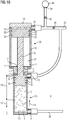
- FIG 10 shows cross-section II - II of the hydraulic apparatus 1, which is in the second operating stage II, in other words when the pressure of the second pressure line 38 has filled the plus chamber 13 of the drainage section 26 through the connector 9 and pushed, by means of a plus movement 14, the piston 5 and further the piston rod 6 into contact with the wall 19 of the tank section 23, and pushed the wall 19 in front of it towards the end 18 of the tank section 23.
- the overflow oil goes to the first pressure line 37.
- the hydraulic oil that was in the minus chamber 11 of the drainage section 25 has exited through the connector 10 to the first pressure line 37.
- the gas space 24 of the tank section 25, which gas space 24 had increased the volume, has been filled by air that has come through the air opening 22.
- FIG 11 shows cross-section II - II of the hydraulic apparatus 1, which is in the final stage of the first operating stage I, in other words when the pressure of the first pressure line 37 has filled the minus chamber 11 through the connector 10 and pushed, by means of a minus movement 12, the piston 5 and piston rod 6 towards the end 3 of the drainage section 25, in which case the wall 19 of the tank section 25 has been able to move towards the end 17 and enabled the access of the overflow oil of the hydraulic motor 49 into the liquid space 23 of the tank section 25 through the first pressure line 37 and connector 21.
- the hydraulic oil of the plus chamber of the drainage section 26 has exited through the connector 9 to the second pressure line 38. Air has partially exited the gas space 24 of the tank section 25, which gas space 24 has lost some of its volume, through the air opening 22.
- FIG 12 shows cross-section II - II of the hydraulic apparatus 1, which is in the first operating stage I, in other words when the pressure of the first pressure line 37 has filled the minus chamber 11 through the connector 10 and pushed the piston 5 and piston rod 6 towards the end 3 of the drainage section 25, whereby the wall 19 of the tank section 25 has been able to move towards the end 17 and enabled the partial access of the overflow oil of the hydraulic motor 49 into the liquid space 23 of the tank section 25 through the first pressure line 37 and connector 21.
- the hydraulic oil of the plus chamber of the drainage section 26 has exited through the connector 9 to the second pressure line 38. Air has partially exited the gas space 24, which has lost some of its volume, through the air opening 22.
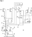
- FIG 1 shows work device 100 usable with pressure circulation and equipped with a hydraulic motor, in other words the hydraulic system 29 of the saw grab shown in FIG 4 .
- the work device 100 comprises i) a hydraulic circulation 55, which has a first pressure line 37 and a second pressure line 38.
- the work device 100 has a hydraulic motor 49.
- the hydraulic motor 100 has most advantageously been connected or is connectable between the first pressure line 37 and the second pressure line 38.
- the hydraulic motor 100 has an overflow connection 54.
- the work device 100 further comprises a hydraulic apparatus 1 in accordance with the first aspect of the invention, which hydraulic apparatus 1 has been configured to receive overflow oil from the hydraulic motor 49 through a non-return valve 46 and return overflow oil to the pressure circulation 55 through a second non-return valve 45.
- the first pressure line 37 and the second pressure line 38 have most preferably been connected or are connectable to a hydraulic power unit 30.
- the work device 100 can also comprise a number of grabs 104, 105 and at least one hydraulic cylinder 42, which has most advantageously been connected or is connectable to one of the two pressure lines 37, 38 to close the grabs 104, 105 and to the other pressure line 37, 38 to open the grabs 104, 105.
- the hydraulic cylinder 42 can further comprise a non-return valve 39, which has most preferably been connected or is connectable to the first pressure line 37.
- the work device 100 can further comprise a body 101 and at least one hydraulic cylinder 43, which has most advantageously been connected or is connectable to the first pressure line 37 to turn the body 101 with respect to the arm 110 to the first position, especially essentially to an angle of 0°, and to the second pressure line 38 to turn the body 101 with respect to the boom 110 to the second position, especially essentially to an angle of 90°.
- the hydraulic cylinder 43 can further comprise pressure relief valves 40, 41, which have most advantageously been connected or are connectable in parallel to the second pressure line 38.
- the hydraulic motor 49 of the work device 100 is most advantageously the motor of a hydraulically-operated chain saw 107.
- the work device 100 further comprises a hydraulic cylinder 52, which has most advantageously been connected or is connectable to the first pressure line 37 to turn the chain saw 107 to the cutting position and to the second pressure line 38 to return the chain saw 107 to the rest position.
- the hydraulic cylinder 52 can further comprise a pressure reducing valve / pressure relief valve 50, which has most advantageously been connected or is connectable to the first pressure line 37.
- the hydraulic cylinder 52 can further comprise a directional control valve 51, which has most advantageously been connected or is connectable both to the first pressure line 37 and to the second pressure line 38.
- a chain lubrication unit 53 has most advantageously been arranged in connection with the chain saw 107, which chain lubrication unit 53 has most advantageously been connected or is connectable to the second pressure line 38.
- the chain lubrication unit 53 can further comprise a non-return valve 47, which has most advantageously been connected or is connectable to the first pressure line 37.
- the hydraulic motor 49 can comprise a non-return valve 44, which has most advantageously been connected or is connectable to the second pressure line 38.
- the hydraulic motor 49 can further comprise a directional control valve 48, which has most advantageously been connected or is connectable to the first pressure line 37.
- the work device 100 is most advantageously a hydraulically-operated gripping device or grab intended for the collection and cutting of timber, the hydraulic motor 49 of which work device 100 is most preferably the motor of a hydraulically-operated chain saw 107.
- the second operating stage II of the hydraulic apparatus 1 of the work device 100 is when the motor of the chain saw 107 is rotating, and the first operating stage I is when the gripping device or grab is being opened, in which case the motor of the chain saw 107 is not run.
- FIG 3 - 9 show one embodiment of the saw grab, where the work device 100 further comprises a body 101, at least two grabs 104, 105 articulated to the body 101, an arm 110 articulated to the body 101 and a work device mounting 108 fastened to the arm 110.
- the drawing FIG 3 shows the work device 100 in a perspective view.
- the drawing FIG 8 shows the work device 100 viewed from above and FIG 9 viewed from below.
- the work device 100 can be fastened to a work machine, such as an excavator boom, by means of the work device mounting 108.
- the work device mounting 108 has most advantageously been fastened to the end of the arm 110 by welding.
- the arm 110 has been articulated to the body 101.
- the body 101 can turn with respect to the arm 110 most advantageously 0° - 90°.
- the turning of the body 101 most preferably takes place by means of a hydraulic cylinder 34.
- the hydraulic apparatus 1, the oil tank 102 of the chain lubrication unit 53 and the protective casing 103 of the valve blocks 109 have been fastened to the arm 110, in which case they do not turn with the body 101.
- the grabs 104 and 105 have been articulated to the body 101.
- the grabs 104 and 105 open and close by means of the hydraulic cylinder 42.
- the chain saw 107 has been articulated to the body 101.
- the chain saw 107 is in the rest position inside a chain guard 106.
- the chain guard 106 which has most advantageously been made as a welded structure, has been connected to the body 101.
- FIG 4 shows the work device 100 viewed from the back.
- the grabs 104 and 105 seize the item, such as a tree trunk, by squeezing it with the closing grabs 104 and 105.
- the tree trunk is cut by bringing the chain saw 107 out of the chain guard 106 and by pressing it against the tree.
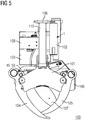
- FIG 5 shows the work device 100 viewed from the front.
- the hydraulic motor 49 and the chain lubrication unit 53 have most advantageously been connected to the body and arranged so that the hydraulic motor 49 rotates the chain saw 107 and the chain lubrication unit lubricates the chain of the chain saw 107. It is possible that at least some of the valves have been combined into valve blocks 109 and located most advantageously in a protective casing 103 fastened to the arm 110.
- the hydraulic apparatus 1 has been connected to the arm 110 in the direction of the arm 110.
- FIG 6 shows the work device 100 viewed from the right side.
- the chain saw 107 has most advantageously been located below the grabs 104 and 105, when the body 101 is turned to an angle of for example 90° with respect to the arm 110.
- the distance of the chain saw 107 from the grabs 104 and 105 is most advantageously 300 - 500 mm.
- FIG 7 shows the work device 100 viewed from the left side.
- the hydraulic motor 49 is most advantageously at least partially inside the chain guard 106.
Landscapes
- Engineering & Computer Science (AREA)
- Mechanical Engineering (AREA)
- General Engineering & Computer Science (AREA)
- Chemical & Material Sciences (AREA)
- Fluid Mechanics (AREA)
- Physics & Mathematics (AREA)
- Analytical Chemistry (AREA)
- Life Sciences & Earth Sciences (AREA)
- Combustion & Propulsion (AREA)
- Biodiversity & Conservation Biology (AREA)
- Ecology (AREA)
- Forests & Forestry (AREA)
- Environmental Sciences (AREA)
- Shovels (AREA)
- Fluid-Pressure Circuits (AREA)
- Supply Devices, Intensifiers, Converters, And Telemotors (AREA)
Claims (14)
- Dispositif de travail (100) utilisable avec une circulation de pression et équipé d'un moteur hydraulique, comprenant :- une circulation hydraulique (55) présentant une première ligne de pression (37) et une deuxième ligne de pression (38) ;- un moteur hydraulique (49) connecté entre la première ligne de pression (37) et la deuxième ligne de pression (38) et raccordé à un trop-plein (54) ; etcaractérisé en ce que ledit dispositif de travail (100) comprend également- un dispositif hydraulique (1) pour la réception et le retour à la circulation de la pression du trop-plein d'huile du moteur hydraulique, dans lequel ledit dispositif hydraulique (1) comprend :le dispositif hydraulique (1) ayant été configuré pour recevoir le trop-plein d'huile du moteur hydraulique (49) à travers une valve antiretour (46) et pour renvoyer le trop-plein d'huile dans la circulation hydraulique (55) à travers une deuxième valve antiretour (45).- une section de réservoir (26), comprenant un espace de liquide étanche (23) connecté à au moins un connecteur (21), le volume dudit espace de liquide (23) étant limité par au moins une paroi mobile (19) ; et- une section de drainage (25) qui a été configurée au cours d'une première étage de fonctionnement (I) pour effectuer une réduction du volume de l'espace de liquide (23) en déplaçant la paroi (19) et dans une deuxième étape de fonctionnement (II) pour libérer la paroi (19) afin de permettre une augmentation du volume du l'espace de liquide (23) ; et dans lequel :- un dispositif hydraulique (1) a été agencé lors de la première étape de fonctionnement (I) pour renvoyer le trop-plein d'huile dans la circulation hydraulique (55) à travers une valve antiretour (45) et lors de la deuxième étape de fonctionnement (II) pour recevoir le trop-plein d'huile venant du moteur hydraulique (49) à travers une deuxième valve antiretour (46) ;
- Dispositif de travail (100) selon la revendication 1, dans lequel la section de drainage (25) comprend une enveloppe cylindrique (2) et des embouts (3, 4) aux deux extrémités de l'enveloppe (2).
- Dispositif de travail (100) selon la revendication 2, dans lequel la section de drainage (25) comprend un piston mobile (5) et une tige de piston (6) entre les embouts (3, 4) à l'intérieur de l'enveloppe cylindrique (2).
- Dispositif de travail (100) selon l'une quelconque des revendications précédentes 1 à 3, dans lequel la section de drainage (25) comprend un connecteur (10), connecté ou connectable à la circulation hydraulique (55) pour permettre le déplacement de la paroi (19), permettant d'augmenter le volume de l'espace de liquide (23), en particulier par poussée du piston mobile (5) et/ou de la tige de piston (6) afin d'éviter le mouvement de la paroi (19).
- Dispositif de travail (100) selon l'une quelconque des revendications précédentes 1 à 4, dans lequel la section de drainage (25) comprend un connecteur (10), connecté ou connectable à la circulation hydraulique (55) pour permettre de réduire le volume de l'espace de liquide (23) en déplaçant la paroi (19), en particulier en la poussant au moyen du piston mobile (5) et/ou de la tige de piston (6).
- Dispositif de travail (100) selon l'une quelconque des revendications précédentes 1 à 5, dans lequel la section de réservoir (26) comprend au moins un connecteur (10), connecté ou connectable à la circulation hydraulique (55) lors de la première étape de fonctionnement (I) pour renvoyer le trop-plein d'huile dans la circulation hydraulique (55) à travers une valve antiretour (45) et lors de la deuxième étape de fonctionnement (II) pour recevoir le trop-plein d'huile venant du moteur hydraulique (49) à travers une deuxième valve antiretour (46).
- Dispositif de travail (100) selon l'une quelconque des revendications précédentes 1 à 6, dans lequel la section de réservoir (26) comprend une entrée d'air (22) permettant d'assurer la contrepression constante exercée par la paroi (19).
- Dispositif de travail (100) selon l'une quelconque des revendications précédentes, dans lequel la première ligne de pression (37) et la seconde ligne de pression (38) sont connectées ou connectables à une unité de puissance hydraulique (30).
- Dispositif de travail (100) selon l'une quelconque des revendications précédentes, lequel dispositif de travail (100) comprend plusieurs grappins (104, 105) et au moins un cylindre hydraulique (42), lequel est connecté ou connectable à l'une des deux lignes de pression (37, 38) pour fermer les grappins (104, 105) et à l'autre ligne de pression (37, 38) pour ouvrir les grappins (104, 105).
- Dispositif de travail (100) selon l'une quelconque des revendications précédentes, lequel dispositif de travail (100) comprend un corps (101) et au moins un cylindre hydraulique (43) connecté ou connectable à la première ligne de pression (37) pour faire pivoter le corps (101) par rapport au bras (110) dans la première position, en particulier à un angle de 0°, et à la deuxième ligne de pression (38) pour faire pivoter le corps (101) par rapport à la perche (110) dans la seconde position, en particulier à un angle de 90°.
- Dispositif de travail (100) selon l'une quelconque des revendications précédentes, dans lequel le moteur hydraulique (49) est le moteur d'une scie à chaîne hydraulique (107), ledit dispositif de travail comprenant par ailleurs un cylindre hydraulique (52) connecté ou connectable à la première ligne de pression (37) pour faire pivoter la scie à chaîne (107) en position de coupe et à la deuxième ligne de pression (38) pour replacer la scie à chaîne (107) en position de repos.
- Dispositif de travail (100) selon l'une quelconque des revendications précédentes, dans lequel ledit dispositif de travail (100) est un dispositif de préhension hydraulique ou un grappin destiné à la collecte et à la coupe de bois, et dans lequel le moteur hydraulique (49) est le moteur d'une scie à chaîne hydraulique (107).
- Dispositif de travail (100) selon la revendication 12, dans lequel la rotation du moteur de la scie à chaîne constitue la deuxième étape de fonctionnement (II) du dispositif hydraulique (1).
- Dispositif de travail (100) selon la revendication 12 ou la revendication 13, dans lequel la première étape de fonctionnement (I) du dispositif hydraulique (1) correspond à l'ouverture du dispositif de préhension ou du grappin, auquel cas le moteur de la scie à chaîne (107) ne fonctionne pas.
Applications Claiming Priority (1)
| Application Number | Priority Date | Filing Date | Title |
|---|---|---|---|
| FI20155396A FI127542B (fi) | 2015-05-26 | 2015-05-26 | Hydrauliaparaatti hydraulimoottorin ylivuotoöljyn vastaanottamiseksi ja painekiertoon palauttamiseksi ja painekierrolla käytettävissä oleva hydraulimoottorilla varustettu työlaite |
Publications (2)
| Publication Number | Publication Date |
|---|---|
| EP3097772A1 EP3097772A1 (fr) | 2016-11-30 |
| EP3097772B1 true EP3097772B1 (fr) | 2018-01-31 |
Family
ID=55913435
Family Applications (1)
| Application Number | Title | Priority Date | Filing Date |
|---|---|---|---|
| EP16159112.8A Active EP3097772B1 (fr) | 2015-05-26 | 2016-03-08 | Réservoir de compensation à volume variable pour un moteur hydraulique, pour absorber un trop-plein d'huile |
Country Status (2)
| Country | Link |
|---|---|
| EP (1) | EP3097772B1 (fr) |
| FI (1) | FI127542B (fr) |
Cited By (1)
| Publication number | Priority date | Publication date | Assignee | Title |
|---|---|---|---|---|
| US20230264926A1 (en) * | 2020-08-20 | 2023-08-24 | Komatsu Forest Ab | Adaptive control of a hydraulic timber grip on a timber handling device |
Families Citing this family (4)
| Publication number | Priority date | Publication date | Assignee | Title |
|---|---|---|---|---|
| FI127299B (fi) * | 2017-05-16 | 2018-03-15 | Biojack Oy | Järjestelmä hydraulisylinterin työkyvyn lisäämiseksi sekä hydraulikäyttöinen koura |
| US11536299B2 (en) * | 2020-09-30 | 2022-12-27 | Jack Kevin Lippett | Methods and hydraulic apparatus |
| AT525123B1 (de) * | 2021-06-02 | 2024-12-15 | Werner Steininger | Vorrichtung zur holzernte |
| AT525122B1 (de) * | 2021-06-02 | 2024-12-15 | Werner Steininger | Vorrichtung zur holzernte |
Family Cites Families (4)
| Publication number | Priority date | Publication date | Assignee | Title |
|---|---|---|---|---|
| EP0298635A3 (fr) * | 1987-07-09 | 1991-04-24 | Melea Limited | Récipient à capacité variable et méthode pour son utilisation |
| DE102007034315A1 (de) * | 2007-07-24 | 2009-07-09 | Trw Automotive Gmbh | Druckspeicher für einen geschlossenen Hydraulikkreis eines Kraftfahrzeug-Lenksystems |
| CA2650748A1 (fr) * | 2009-01-23 | 2010-07-23 | Rotobec Inc. | Systeme hydraulique pour tronconneuse a grappin |
| NL1037718C2 (nl) | 2009-12-23 | 2011-06-27 | Michel Bernardus Johanna Gierkink | Kop voor het oogsten van bomen en voertuig voorzien van een dergelijke kop. |
-
2015
- 2015-05-26 FI FI20155396A patent/FI127542B/fi active IP Right Grant
-
2016
- 2016-03-08 EP EP16159112.8A patent/EP3097772B1/fr active Active
Non-Patent Citations (1)
| Title |
|---|
| None * |
Cited By (1)
| Publication number | Priority date | Publication date | Assignee | Title |
|---|---|---|---|---|
| US20230264926A1 (en) * | 2020-08-20 | 2023-08-24 | Komatsu Forest Ab | Adaptive control of a hydraulic timber grip on a timber handling device |
Also Published As
| Publication number | Publication date |
|---|---|
| EP3097772A1 (fr) | 2016-11-30 |
| FI20155396A7 (fi) | 2016-11-27 |
| FI127542B (fi) | 2018-08-31 |
Similar Documents
| Publication | Publication Date | Title |
|---|---|---|
| EP3097772B1 (fr) | Réservoir de compensation à volume variable pour un moteur hydraulique, pour absorber un trop-plein d'huile | |
| KR101722483B1 (ko) | 장착가능한 유압 장치를 작동시키는 방법, 및 특히 파괴나 분쇄 또는 재생처리를 위한 이러한 장착가능한 유압 장치 | |
| EP2515628B1 (fr) | Tête de coupe d'arbres et véhicule équipé d'une tête de ce type | |
| EP3523541B1 (fr) | Grappin à bois | |
| CA2926998A1 (fr) | Appareillage de grappin double action | |
| EP2082985A1 (fr) | Treuil avec équilibrage de charge | |
| FI13474Y1 (fi) | Hydraulinen toimilaite, työlaite ja energiapuukoura | |
| WO2015190972A1 (fr) | Vérin hydraulique | |
| WO2015136155A1 (fr) | Grappin à bois de feu et accessoire de grappin à bois de feu | |
| NO313208B1 (no) | Ventilelement | |
| US12114614B2 (en) | Gripper | |
| EP3404272A1 (fr) | Système permettant d'augmenter la capacité de travail d'un cylindre hydraulique et grappin commandé hydrauliquement | |
| FI127334B (fi) | Hydrauliaparaatti hydraulimoottorin ylivuotoöljyn vastaanottamiseksi ja painekiertoon palauttamiseksi ja painekierrolla käytettävissä oleva hydraulimoottorilla varustettu työlaite | |
| EP1688546A3 (fr) | Vérin, de préférence pour une benne preneuse | |
| EP4085755A1 (fr) | Tête d'abattage hydraulique pour des troncs ou branches d'arbres adapté au montage sur une machine de travail | |
| WO2017018886A1 (fr) | Actionneur hydraulique | |
| WO2013126558A2 (fr) | Remplacement de conduite sans tranchée d'une conduite souterraine | |
| JP2018021405A (ja) | 油圧駆動装置 | |
| CN210290360U (zh) | 油缸抗冲击保护装置 | |
| US9103356B2 (en) | Oil-pressure apparatus | |
| CN202612248U (zh) | 一种组合式液压缸 | |
| FR3028589A1 (fr) | Verin hydraulique a transfert de volume interne | |
| FI12268U1 (fi) | Hydraulinen toimilaite, järjestelmä hydraulisen toimilaitteen toiminnan ohjaamiseksi ja energiapuukoura | |
| FI127585B (fi) | Energiapuukoura | |
| EP2655748B1 (fr) | Appareil de martelage |
Legal Events
| Date | Code | Title | Description |
|---|---|---|---|
| PUAI | Public reference made under article 153(3) epc to a published international application that has entered the european phase |
Free format text: ORIGINAL CODE: 0009012 |
|
| AK | Designated contracting states |
Kind code of ref document: A1 Designated state(s): AL AT BE BG CH CY CZ DE DK EE ES FI FR GB GR HR HU IE IS IT LI LT LU LV MC MK MT NL NO PL PT RO RS SE SI SK SM TR |
|
| AX | Request for extension of the european patent |
Extension state: BA ME |
|
| 17P | Request for examination filed |
Effective date: 20170317 |
|
| RBV | Designated contracting states (corrected) |
Designated state(s): AL AT BE BG CH CY CZ DE DK EE ES FI FR GB GR HR HU IE IS IT LI LT LU LV MC MK MT NL NO PL PT RO RS SE SI SK SM TR |
|
| GRAP | Despatch of communication of intention to grant a patent |
Free format text: ORIGINAL CODE: EPIDOSNIGR1 |
|
| INTG | Intention to grant announced |
Effective date: 20171026 |
|
| GRAS | Grant fee paid |
Free format text: ORIGINAL CODE: EPIDOSNIGR3 |
|
| GRAA | (expected) grant |
Free format text: ORIGINAL CODE: 0009210 |
|
| AK | Designated contracting states |
Kind code of ref document: B1 Designated state(s): AL AT BE BG CH CY CZ DE DK EE ES FI FR GB GR HR HU IE IS IT LI LT LU LV MC MK MT NL NO PL PT RO RS SE SI SK SM TR |
|
| REG | Reference to a national code |
Ref country code: GB Ref legal event code: FG4D Ref country code: CH Ref legal event code: EP |
|
| REG | Reference to a national code |
Ref country code: AT Ref legal event code: REF Ref document number: 966496 Country of ref document: AT Kind code of ref document: T Effective date: 20180215 |
|
| REG | Reference to a national code |
Ref country code: IE Ref legal event code: FG4D |
|
| REG | Reference to a national code |
Ref country code: DE Ref legal event code: R096 Ref document number: 602016001476 Country of ref document: DE |
|
| REG | Reference to a national code |
Ref country code: SE Ref legal event code: TRGR |
|
| REG | Reference to a national code |
Ref country code: NL Ref legal event code: FP |
|
| REG | Reference to a national code |
Ref country code: FR Ref legal event code: PLFP Year of fee payment: 3 |
|
| REG | Reference to a national code |
Ref country code: LT Ref legal event code: MG4D |
|
| PG25 | Lapsed in a contracting state [announced via postgrant information from national office to epo] |
Ref country code: ES Free format text: LAPSE BECAUSE OF FAILURE TO SUBMIT A TRANSLATION OF THE DESCRIPTION OR TO PAY THE FEE WITHIN THE PRESCRIBED TIME-LIMIT Effective date: 20180131 Ref country code: NO Free format text: LAPSE BECAUSE OF FAILURE TO SUBMIT A TRANSLATION OF THE DESCRIPTION OR TO PAY THE FEE WITHIN THE PRESCRIBED TIME-LIMIT Effective date: 20180430 Ref country code: HR Free format text: LAPSE BECAUSE OF FAILURE TO SUBMIT A TRANSLATION OF THE DESCRIPTION OR TO PAY THE FEE WITHIN THE PRESCRIBED TIME-LIMIT Effective date: 20180131 Ref country code: LT Free format text: LAPSE BECAUSE OF FAILURE TO SUBMIT A TRANSLATION OF THE DESCRIPTION OR TO PAY THE FEE WITHIN THE PRESCRIBED TIME-LIMIT Effective date: 20180131 |
|
| PG25 | Lapsed in a contracting state [announced via postgrant information from national office to epo] |
Ref country code: BG Free format text: LAPSE BECAUSE OF FAILURE TO SUBMIT A TRANSLATION OF THE DESCRIPTION OR TO PAY THE FEE WITHIN THE PRESCRIBED TIME-LIMIT Effective date: 20180430 Ref country code: IS Free format text: LAPSE BECAUSE OF FAILURE TO SUBMIT A TRANSLATION OF THE DESCRIPTION OR TO PAY THE FEE WITHIN THE PRESCRIBED TIME-LIMIT Effective date: 20180531 Ref country code: LV Free format text: LAPSE BECAUSE OF FAILURE TO SUBMIT A TRANSLATION OF THE DESCRIPTION OR TO PAY THE FEE WITHIN THE PRESCRIBED TIME-LIMIT Effective date: 20180131 Ref country code: PL Free format text: LAPSE BECAUSE OF FAILURE TO SUBMIT A TRANSLATION OF THE DESCRIPTION OR TO PAY THE FEE WITHIN THE PRESCRIBED TIME-LIMIT Effective date: 20180131 Ref country code: GR Free format text: LAPSE BECAUSE OF FAILURE TO SUBMIT A TRANSLATION OF THE DESCRIPTION OR TO PAY THE FEE WITHIN THE PRESCRIBED TIME-LIMIT Effective date: 20180501 Ref country code: RS Free format text: LAPSE BECAUSE OF FAILURE TO SUBMIT A TRANSLATION OF THE DESCRIPTION OR TO PAY THE FEE WITHIN THE PRESCRIBED TIME-LIMIT Effective date: 20180131 |
|
| PG25 | Lapsed in a contracting state [announced via postgrant information from national office to epo] |
Ref country code: IT Free format text: LAPSE BECAUSE OF FAILURE TO SUBMIT A TRANSLATION OF THE DESCRIPTION OR TO PAY THE FEE WITHIN THE PRESCRIBED TIME-LIMIT Effective date: 20180131 Ref country code: RO Free format text: LAPSE BECAUSE OF FAILURE TO SUBMIT A TRANSLATION OF THE DESCRIPTION OR TO PAY THE FEE WITHIN THE PRESCRIBED TIME-LIMIT Effective date: 20180131 Ref country code: AL Free format text: LAPSE BECAUSE OF FAILURE TO SUBMIT A TRANSLATION OF THE DESCRIPTION OR TO PAY THE FEE WITHIN THE PRESCRIBED TIME-LIMIT Effective date: 20180131 Ref country code: EE Free format text: LAPSE BECAUSE OF FAILURE TO SUBMIT A TRANSLATION OF THE DESCRIPTION OR TO PAY THE FEE WITHIN THE PRESCRIBED TIME-LIMIT Effective date: 20180131 |
|
| REG | Reference to a national code |
Ref country code: DE Ref legal event code: R097 Ref document number: 602016001476 Country of ref document: DE |
|
| PG25 | Lapsed in a contracting state [announced via postgrant information from national office to epo] |
Ref country code: DK Free format text: LAPSE BECAUSE OF FAILURE TO SUBMIT A TRANSLATION OF THE DESCRIPTION OR TO PAY THE FEE WITHIN THE PRESCRIBED TIME-LIMIT Effective date: 20180131 Ref country code: SM Free format text: LAPSE BECAUSE OF FAILURE TO SUBMIT A TRANSLATION OF THE DESCRIPTION OR TO PAY THE FEE WITHIN THE PRESCRIBED TIME-LIMIT Effective date: 20180131 Ref country code: CZ Free format text: LAPSE BECAUSE OF FAILURE TO SUBMIT A TRANSLATION OF THE DESCRIPTION OR TO PAY THE FEE WITHIN THE PRESCRIBED TIME-LIMIT Effective date: 20180131 Ref country code: MC Free format text: LAPSE BECAUSE OF FAILURE TO SUBMIT A TRANSLATION OF THE DESCRIPTION OR TO PAY THE FEE WITHIN THE PRESCRIBED TIME-LIMIT Effective date: 20180131 Ref country code: SK Free format text: LAPSE BECAUSE OF FAILURE TO SUBMIT A TRANSLATION OF THE DESCRIPTION OR TO PAY THE FEE WITHIN THE PRESCRIBED TIME-LIMIT Effective date: 20180131 |
|
| PLBE | No opposition filed within time limit |
Free format text: ORIGINAL CODE: 0009261 |
|
| STAA | Information on the status of an ep patent application or granted ep patent |
Free format text: STATUS: NO OPPOSITION FILED WITHIN TIME LIMIT |
|
| REG | Reference to a national code |
Ref country code: BE Ref legal event code: MM Effective date: 20180331 |
|
| REG | Reference to a national code |
Ref country code: IE Ref legal event code: MM4A |
|
| PG25 | Lapsed in a contracting state [announced via postgrant information from national office to epo] |
Ref country code: LU Free format text: LAPSE BECAUSE OF NON-PAYMENT OF DUE FEES Effective date: 20180308 |
|
| 26N | No opposition filed |
Effective date: 20181102 |
|
| PG25 | Lapsed in a contracting state [announced via postgrant information from national office to epo] |
Ref country code: IE Free format text: LAPSE BECAUSE OF NON-PAYMENT OF DUE FEES Effective date: 20180308 |
|
| PG25 | Lapsed in a contracting state [announced via postgrant information from national office to epo] |
Ref country code: BE Free format text: LAPSE BECAUSE OF NON-PAYMENT OF DUE FEES Effective date: 20180331 Ref country code: SI Free format text: LAPSE BECAUSE OF FAILURE TO SUBMIT A TRANSLATION OF THE DESCRIPTION OR TO PAY THE FEE WITHIN THE PRESCRIBED TIME-LIMIT Effective date: 20180131 |
|
| REG | Reference to a national code |
Ref country code: CH Ref legal event code: PL |
|
| PG25 | Lapsed in a contracting state [announced via postgrant information from national office to epo] |
Ref country code: CH Free format text: LAPSE BECAUSE OF NON-PAYMENT OF DUE FEES Effective date: 20190331 Ref country code: LI Free format text: LAPSE BECAUSE OF NON-PAYMENT OF DUE FEES Effective date: 20190331 Ref country code: MT Free format text: LAPSE BECAUSE OF NON-PAYMENT OF DUE FEES Effective date: 20180308 |
|
| PG25 | Lapsed in a contracting state [announced via postgrant information from national office to epo] |
Ref country code: TR Free format text: LAPSE BECAUSE OF FAILURE TO SUBMIT A TRANSLATION OF THE DESCRIPTION OR TO PAY THE FEE WITHIN THE PRESCRIBED TIME-LIMIT Effective date: 20180131 |
|
| PG25 | Lapsed in a contracting state [announced via postgrant information from national office to epo] |
Ref country code: PT Free format text: LAPSE BECAUSE OF FAILURE TO SUBMIT A TRANSLATION OF THE DESCRIPTION OR TO PAY THE FEE WITHIN THE PRESCRIBED TIME-LIMIT Effective date: 20180131 |
|
| PG25 | Lapsed in a contracting state [announced via postgrant information from national office to epo] |
Ref country code: HU Free format text: LAPSE BECAUSE OF FAILURE TO SUBMIT A TRANSLATION OF THE DESCRIPTION OR TO PAY THE FEE WITHIN THE PRESCRIBED TIME-LIMIT; INVALID AB INITIO Effective date: 20160308 Ref country code: MK Free format text: LAPSE BECAUSE OF NON-PAYMENT OF DUE FEES Effective date: 20180131 Ref country code: CY Free format text: LAPSE BECAUSE OF FAILURE TO SUBMIT A TRANSLATION OF THE DESCRIPTION OR TO PAY THE FEE WITHIN THE PRESCRIBED TIME-LIMIT Effective date: 20180131 |
|
| PGFP | Annual fee paid to national office [announced via postgrant information from national office to epo] |
Ref country code: FR Payment date: 20210324 Year of fee payment: 6 Ref country code: NL Payment date: 20210319 Year of fee payment: 6 |
|
| PGFP | Annual fee paid to national office [announced via postgrant information from national office to epo] |
Ref country code: GB Payment date: 20210324 Year of fee payment: 6 Ref country code: AT Payment date: 20210322 Year of fee payment: 6 Ref country code: SE Payment date: 20210319 Year of fee payment: 6 |
|
| REG | Reference to a national code |
Ref country code: AT Ref legal event code: UEP Ref document number: 966496 Country of ref document: AT Kind code of ref document: T Effective date: 20180131 |
|
| REG | Reference to a national code |
Ref country code: NL Ref legal event code: MM Effective date: 20220401 |
|
| REG | Reference to a national code |
Ref country code: AT Ref legal event code: MM01 Ref document number: 966496 Country of ref document: AT Kind code of ref document: T Effective date: 20220308 |
|
| GBPC | Gb: european patent ceased through non-payment of renewal fee |
Effective date: 20220308 |
|
| PG25 | Lapsed in a contracting state [announced via postgrant information from national office to epo] |
Ref country code: SE Free format text: LAPSE BECAUSE OF NON-PAYMENT OF DUE FEES Effective date: 20220309 Ref country code: NL Free format text: LAPSE BECAUSE OF NON-PAYMENT OF DUE FEES Effective date: 20220401 Ref country code: GB Free format text: LAPSE BECAUSE OF NON-PAYMENT OF DUE FEES Effective date: 20220308 Ref country code: FR Free format text: LAPSE BECAUSE OF NON-PAYMENT OF DUE FEES Effective date: 20220331 Ref country code: AT Free format text: LAPSE BECAUSE OF NON-PAYMENT OF DUE FEES Effective date: 20220308 |
|
| PGFP | Annual fee paid to national office [announced via postgrant information from national office to epo] |
Ref country code: DE Payment date: 20260320 Year of fee payment: 11 |
|
| PGFP | Annual fee paid to national office [announced via postgrant information from national office to epo] |
Ref country code: FI Payment date: 20260320 Year of fee payment: 11 |