EP3097864A2 - Unité de chargement de suture - Google Patents
Unité de chargement de suture Download PDFInfo
- Publication number
- EP3097864A2 EP3097864A2 EP16171486.0A EP16171486A EP3097864A2 EP 3097864 A2 EP3097864 A2 EP 3097864A2 EP 16171486 A EP16171486 A EP 16171486A EP 3097864 A2 EP3097864 A2 EP 3097864A2
- Authority
- EP
- European Patent Office
- Prior art keywords
- needle
- knife
- carriage
- helical
- suture
- Prior art date
- Legal status (The legal status is an assumption and is not a legal conclusion. Google has not performed a legal analysis and makes no representation as to the accuracy of the status listed.)
- Granted
Links
Images










Classifications
-
- A—HUMAN NECESSITIES
- A61—MEDICAL OR VETERINARY SCIENCE; HYGIENE
- A61B—DIAGNOSIS; SURGERY; IDENTIFICATION
- A61B17/00—Surgical instruments, devices or methods
- A61B17/04—Surgical instruments, devices or methods for suturing wounds; Holders or packages for needles or suture materials
-
- A—HUMAN NECESSITIES
- A61—MEDICAL OR VETERINARY SCIENCE; HYGIENE
- A61B—DIAGNOSIS; SURGERY; IDENTIFICATION
- A61B17/00—Surgical instruments, devices or methods
- A61B17/04—Surgical instruments, devices or methods for suturing wounds; Holders or packages for needles or suture materials
- A61B17/0469—Suturing instruments for use in minimally invasive surgery, e.g. endoscopic surgery
-
- A—HUMAN NECESSITIES
- A61—MEDICAL OR VETERINARY SCIENCE; HYGIENE
- A61B—DIAGNOSIS; SURGERY; IDENTIFICATION
- A61B17/00—Surgical instruments, devices or methods
- A61B17/04—Surgical instruments, devices or methods for suturing wounds; Holders or packages for needles or suture materials
- A61B17/0467—Instruments for cutting sutures
-
- A—HUMAN NECESSITIES
- A61—MEDICAL OR VETERINARY SCIENCE; HYGIENE
- A61B—DIAGNOSIS; SURGERY; IDENTIFICATION
- A61B17/00—Surgical instruments, devices or methods
- A61B17/04—Surgical instruments, devices or methods for suturing wounds; Holders or packages for needles or suture materials
- A61B17/0482—Needle or suture guides
-
- A—HUMAN NECESSITIES
- A61—MEDICAL OR VETERINARY SCIENCE; HYGIENE
- A61B—DIAGNOSIS; SURGERY; IDENTIFICATION
- A61B17/00—Surgical instruments, devices or methods
- A61B17/04—Surgical instruments, devices or methods for suturing wounds; Holders or packages for needles or suture materials
- A61B17/0491—Sewing machines for surgery
-
- A—HUMAN NECESSITIES
- A61—MEDICAL OR VETERINARY SCIENCE; HYGIENE
- A61B—DIAGNOSIS; SURGERY; IDENTIFICATION
- A61B17/00—Surgical instruments, devices or methods
- A61B17/04—Surgical instruments, devices or methods for suturing wounds; Holders or packages for needles or suture materials
- A61B17/06—Needles ; Sutures; Needle-suture combinations; Holders or packages for needles or suture materials
-
- A—HUMAN NECESSITIES
- A61—MEDICAL OR VETERINARY SCIENCE; HYGIENE
- A61B—DIAGNOSIS; SURGERY; IDENTIFICATION
- A61B17/00—Surgical instruments, devices or methods
- A61B17/00234—Surgical instruments, devices or methods for minimally invasive surgery
- A61B2017/00353—Surgical instruments, devices or methods for minimally invasive surgery one mechanical instrument performing multiple functions, e.g. cutting and grasping
-
- A—HUMAN NECESSITIES
- A61—MEDICAL OR VETERINARY SCIENCE; HYGIENE
- A61B—DIAGNOSIS; SURGERY; IDENTIFICATION
- A61B17/00—Surgical instruments, devices or methods
- A61B2017/00526—Methods of manufacturing
- A61B2017/0053—Loading magazines or sutures into applying tools
-
- A—HUMAN NECESSITIES
- A61—MEDICAL OR VETERINARY SCIENCE; HYGIENE
- A61B—DIAGNOSIS; SURGERY; IDENTIFICATION
- A61B17/00—Surgical instruments, devices or methods
- A61B17/04—Surgical instruments, devices or methods for suturing wounds; Holders or packages for needles or suture materials
- A61B17/0469—Suturing instruments for use in minimally invasive surgery, e.g. endoscopic surgery
- A61B2017/0472—Multiple-needled, e.g. double-needled, instruments
-
- A—HUMAN NECESSITIES
- A61—MEDICAL OR VETERINARY SCIENCE; HYGIENE
- A61B—DIAGNOSIS; SURGERY; IDENTIFICATION
- A61B17/00—Surgical instruments, devices or methods
- A61B17/04—Surgical instruments, devices or methods for suturing wounds; Holders or packages for needles or suture materials
- A61B2017/0498—Surgical instruments, devices or methods for suturing wounds; Holders or packages for needles or suture materials for advancing a suture filament along a helical path through tissue
-
- A—HUMAN NECESSITIES
- A61—MEDICAL OR VETERINARY SCIENCE; HYGIENE
- A61B—DIAGNOSIS; SURGERY; IDENTIFICATION
- A61B17/00—Surgical instruments, devices or methods
- A61B17/04—Surgical instruments, devices or methods for suturing wounds; Holders or packages for needles or suture materials
- A61B17/06—Needles ; Sutures; Needle-suture combinations; Holders or packages for needles or suture materials
- A61B2017/06052—Needle-suture combinations in which a suture is extending inside a hollow tubular needle, e.g. over the entire length of the needle
-
- A—HUMAN NECESSITIES
- A61—MEDICAL OR VETERINARY SCIENCE; HYGIENE
- A61B—DIAGNOSIS; SURGERY; IDENTIFICATION
- A61B17/00—Surgical instruments, devices or methods
- A61B17/04—Surgical instruments, devices or methods for suturing wounds; Holders or packages for needles or suture materials
- A61B17/06—Needles ; Sutures; Needle-suture combinations; Holders or packages for needles or suture materials
- A61B17/06066—Needles, e.g. needle tip configurations
- A61B2017/06076—Needles, e.g. needle tip configurations helically or spirally coiled
-
- A—HUMAN NECESSITIES
- A61—MEDICAL OR VETERINARY SCIENCE; HYGIENE
- A61B—DIAGNOSIS; SURGERY; IDENTIFICATION
- A61B17/00—Surgical instruments, devices or methods
- A61B17/068—Surgical staplers, e.g. containing multiple staples or clamps
- A61B17/072—Surgical staplers, e.g. containing multiple staples or clamps for applying a row of staples in a single action, e.g. the staples being applied simultaneously
- A61B2017/07214—Stapler heads
- A61B2017/07285—Stapler heads characterised by its cutter
-
- A—HUMAN NECESSITIES
- A61—MEDICAL OR VETERINARY SCIENCE; HYGIENE
- A61B—DIAGNOSIS; SURGERY; IDENTIFICATION
- A61B17/00—Surgical instruments, devices or methods
- A61B17/28—Surgical forceps
- A61B17/29—Forceps for use in minimally invasive surgery
- A61B2017/2926—Details of heads or jaws
-
- A—HUMAN NECESSITIES
- A61—MEDICAL OR VETERINARY SCIENCE; HYGIENE
- A61B—DIAGNOSIS; SURGERY; IDENTIFICATION
- A61B17/00—Surgical instruments, devices or methods
- A61B17/32—Surgical cutting instruments
- A61B2017/320052—Guides for cutting instruments
Definitions
- the present disclosure relates to surgical fastening instruments, and more specifically, to surgical instruments for fastening tissue with continuous sutures.
- a suturing end effector includes a first jaw member, a second jaw member, and a helical needle.
- the first and second jaw members are moveable relative to one another between an open configuration and a closed configuration.
- Each of the first and second jaw members defines a first row of wells which together define a helical path when the first and second jaw members are in the closed configuration.
- the helical needle is rotatable through the helical path from a retracted position to an advanced position to draw a suture through tissue between the first and second jaw members.
- the helical needle is configured to be moveable from the advanced position to the retracted position independent of the suture.
- the helical needle is hollow and defines a channel therethrough.
- the channel may be configured to slidably receive the suture.
- the suturing end effector may include a suture cutter that is disposed within the first jaw member.
- the suture cutter may be moveable from a first position to a second position to cut the suture to leave a portion of the suture within the tissue and a portion of the suture within the channel of the helical needle.
- the suture cutter may be moved to proximally from the first position to the second position in response to movement of the helical needle to the retracted position.
- the suturing end effector may include a knife that is translatable through the first and second jaw members that includes a cam that engages the suture cutter to move the suture cutter from the first position to the second position as the knife is retracted.
- the first and second jaw members each define a portion of a knife slot along a longitudinal axis of the end effector.
- the knife slot may extend through tissue contacting surfaces of the first and second jaw members.
- the first row of wells may be positioned on a first side of the knife slot.
- the suturing end effector may include a knife that is extendable through the knife slot.
- the knife may trail a tip of the helical needle as the helical needle is advanced through the helical path.
- Each of the first and second jaw members may define a clamping groove in a surface that is opposite to the tissue contacting surfaces of the first and second jaw members.
- the knife may include first and second flanges.
- the first flange may be disposed within the clamping groove of the first jaw member and the second flange may be disposed within the clamping groove of the second jaw member.
- the first and second flanges may urge the first and second jaw members towards the closed configuration when the knife is advanced through the knife slot.
- a suturing loading unit in another aspect of the present disclosure, includes a housing, an end effector, and a first helical needle.
- the housing includes a proximal portion, an elongated portion that extends distally from the proximal portion, and a drive mechanism.
- the end effector is supported at a distal end of the elongated portion of the housing.
- the end effector includes first and second jaw members that are moveable relative to one another between open and closed configurations. Each of the first and second jaw members defines a first row of wells that together define a helical path when the first and second jaw members are in the closed configuration.
- the first helical needle is rotatable in response to actuation of the drive mechanism.
- the first helical needle rotatable through the helical path between retracted and advanced positions to draw a suture through tissue between the first and second jaw members.
- the helical needle is configured to be moveable from the advanced position to the retracted position independent of the suture.
- the articulation rod may be configured to articulate the end effector relative to the housing.
- the drive mechanism includes a first drive shaft, a first drive sleeve, and a first needle carriage.
- the first drive shaft may be rotatable within the elongated portion of the housing and may have proximal and distal portions.
- the first drive sleeve may be rotatably secured about the proximal portion of the first drive shaft.
- the first needle carriage may be rotatably secured about the distal portion of the first drive shaft and may be longitudinally translatable through the elongated portion of the housing as the first needle carriage is rotated by the first drive shaft between retracted and advanced positions.
- the first helical needle may be disposed about the first drive shaft and may be coupled to the first needle carriage such that as the first needle carriage is advanced towards the advanced position, the first needle carriage is rotatable advanced through the helical path of the first and second jaw members. As the first needle carriage is retracted towards the retracted position, the first helical needle may be rotatably withdrawn through the helical path of the first and second jaw members.
- the suturing loading unit may include a first suture that passes through a passage defined through the first drive sleeve parallel to the first drive shaft, through a passage defined through the first needle carriage, and into a channel defined through the first helical needle.
- the first needle carriage may include a plurality of nubs that extend radially from an outer surface of the first needle carriage.
- An inner wall of the elongated portion of the housing may define drive grooves.
- Each of the plurality of nubs may be disposed within one of the drive grooves such that as the first needle is rotted by the first drive shaft, each of the plurality of nubs translates within a respective drive groove to translate the first needle carriage within the elongated portion of the housing.
- the drive mechanism includes a second drive shaft, a second drive sleeve, and a second needle.
- the second drive shaft may be rotatable within the elongated portion of the housing and may be parallel to the first drive shaft.
- the second drive shaft may have proximal and distal portions.
- the second drive sleeve may be rotatably secured about the proximal portion of the second drive shaft.
- the second needle carriage may be rotatably secured about the distal portion of the second drive shaft.
- the second needle carriage may be longitudinally translatable through the elongated portion of the housing as the second needle carriage is rotated by the second drive shaft between retracted and advanced positions.
- the suturing loading unit may include a second helical needle that is disposed about the second drive shaft and may be coupled to the second needle carriage such that as the second needle carriage is advanced towards the advanced position.
- the second helical needle is rotatably advanced through a second helical path of the first and second jaw members.
- the second helical needle may be rotatably withdrawn through the second helical path of the first and second jaw members.
- the second helical path may be defined by a second row of wells defined by the first and second jaw members when the first and second jaw members are in the closed configuration.
- the suturing loading unit includes a knife carriage that has a first guide cylinder, a second guide cylinder, and a central portion that is disposed between the first and second guide cylinders.
- the first guide cylinder may be slidably positioned over the first drive shaft and the second guide cylinder may be slidably posited over the second drive shaft.
- the knife carriage may be coupled to a knife that is disposed within the end effector and may be moveable to translate the knife through the first and second jaw members of the end effector.
- the drive mechanism may include knife bars that have proximal and distal ends. The proximal ends of the knife bars may be coupled to the knife carriage and the distal ends of the knife bars may be coupled to the knife.
- the second needle carriage may engage the knife carriage to advance the knife carriage through the elongated portion of the housing as the first needle carriage is retracted.
- the first needle carriage may engage the knife carriage to retract the knife carriage through the elongated portion of the housing.
- the term “clinician” refers to a doctor, a nurse, or any other user, operator, or care provider and may include support personnel.
- proximal refers to the portion of the device or component thereof that is closest to the clinician and the term “distal” refers to the portion of the device or component thereof that is farthest from the clinician.
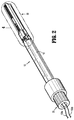
- an exemplary embodiment of a surgical instrument or loading unit 10 provided in accordance with present disclosure and includes a housing 12 and an end effector 30.
- the loading unit 10 is configured to form one or more continuous sutures from suture material in the form of sutures 100a, 100b along a length of the end effector 30 as will be described in detail below.
- the loading unit 10 is driven by a manual drive member 20 that may be manually or electromechanically actuated as described below.
- the loading unit 10 can be configured for connection to a drive member 20 including an electromechanical handpiece 27.
- the electromechanical handpiece 27 can include an adapter 28 that connects the electromechanical handpiece 27 to the loading unit 10.
- an exemplary electromechanical handpiece 27 please refer to commonly owned U.S. Patent Application Serial No. 13/484,975 filed on May 31, 2012 , and published as U.S. Patent Publication No. 2012/0253329 on October 4, 2012 , the entire contents of which is incorporated herein by reference.
- the surgical instrument is illustrated in the form of a loading unit 10, it is envisioned that the surgical instrument can be fixedly secured to a distal end of the electromechanical handpiece 27 and/or adapter 20.
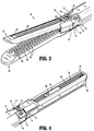
- the end effector 30 includes a first or lower jaw 32 and a second or upper jaw 34 that are moveable relative to one another between an open configuration ( FIG. 3 ) and an approximated or closed configuration ( FIG. 4 ).
- the upper and lower jaws 32, 34 are biased towards the open configuration by a jaw biasing member 31 ( FIG. 6 ) positioned between the jaws 32, 34.
- the upper and lower jaws 32, 34 each define a portion of a knife slot 36 extending along a substantial length of each of the upper and lower jaws 32, 34.
- Each of the upper and lower jaws 32, 34 also defines a clamping channel 38 along an outer surface of each of the respective jaws 32, 34 ( FIG. 10 ) that flanks the knife slot 36.
- a portion of the clamping channel 38 of the lower jaw 32 may form a slot in the lower jaw 32 such that a portion of the clamping channel 38 is recessed within the outer surface of the lower jaw 32.
- the upper and lower jaws 32, 34 each have a tissue contacting surface 35 that defines wells 42.
- the wells 42 are arranged in two parallel rows that are positioned on opposite sides of the knife slot 36. The rows extend in a direction parallel to the longitudinal axis of the end effector 30.
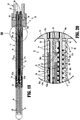
- the wells 42 of the upper and lower jaws 32, 34 form a continuous helical path 43 ( FIG. 21 ) through the upper and lower jaws 32, 34 that extends about the knife slot 36.
- the loading unit 10 includes a housing 12, the end effector 30, a knife mechanism 50, an articulation mechanism 70, and a drive mechanism 80.
- the housing 12 encloses portions of the knife mechanism 50, the articulation mechanism 70, and the drive mechanism 80.
- the housing 12 defines a proximal housing portion 14 and an elongated housing portion 16 extending distally from the proximal housing portion 14.
- the housing 12 includes support tabs 18 that extend distally from the elongated housing portion 16 and receive articulation support pins 73 of a support bracket assembly to pivotally secure the end effector 30 ( FIG. 9 ) to the distal end of the housing 12.
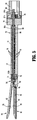
- the elongated housing portion 16 defines a drive channel 17 that extends through the elongated housing portion 16 and drive grooves 19 ( FIG. 5 ) formed along an inner wall that defines the drive channel 17.
- the lower jaw 32 has a proximal portion that defines a plurality of cutter openings 46.
- the cutter openings 46 are dimensioned to receive a suture cutting mechanism 60 that includes a pair of suture cutters 62 and a biasing member 65 ( FIG. 6 ) associated with each of the suture cutters 62.
- Each suture cutter 62 has a body 63 that includes a biasing flange 64, a finger 66, and a cam 68.
- the biasing flange 64 extends laterally from one side of the body 63 and is coupled to an end of the biasing member 65.
- the biasing member 65 is in tension and urges the suture cutter 62 distally and into one of the cutter openings 46.
- each suture cutter 62 extends towards the tissue contacting surface of the upper jaw 34 ( FIG. 5 ) and includes a cutting surface 67.
- the cutting surface 67 is disposed on a proximal and a lower surface of the finger 66 ( FIG. 7 ).
- the cam 68 includes a vertical camming surface 68a and an angled camming surface 68b that are engaged by a cam 59 ( FIG. 8 ) of a knife 54 of the knife mechanism 50 as detailed below to cut a respective one of the sutures 100a, 100b with one of the suture cutters 62.
- the knife mechanism 50 includes resilient knife bars 52 that are translatable through the drive channels 17 to translate the knife 54 through the upper and lower jaws 32, 34.
- the knife 54 includes a blade 55, an upper flange 56, and a lower flange 58.
- the upper and lower flanges 56, 58 form an I-beam configuration with the blade 55.
- the blade 55 is formed on a vertical strut 54a that extends between the upper and lower flanges 56, 58, respectively, and is slidably disposed within the knife slot 36 defined by the upper and lower jaws 32, 34.
- the upper and lower flanges 56, 58 are slidably disposed within the clamping channels 38 of the upper and lower jaws 32, 34 respectively.
- a distal end of the lower flange 58 includes the cam members 59.
- Each of the cam members 59 extends outwardly from the vertical structure 54a in a direction orthogonal to the blade 55 at a position vertically offset from the lower flange 58.
- the cam members 59 are slidably disposed in a camming slot 48 ( FIG. 5 ) defined in the lower jaw 32.
- the articulation mechanism 70 pivotally couples the upper and lower jaws 32, 34 to one another and to the housing 12 to facilitate articulation of the end effector 30 relative to the housing 12.
- the articulation assembly 70 includes a support bracket assembly including an upper bracket 74 and a lower bracket 76 that are secured together by fasteners 75.
- Each of the upper and lower brackets 74, 76 include an articulation support pin 73 extending outward from an upper and lower surface, respectively.
- the articulation support pin 73 extends through openings 18a in tabs 18 of the housing 12 to secure the brackets 74, 76 to the housing 12.
- the lower bracket 76 includes jaw supports 78 that extend laterally from side surfaces of the lower bracket 76 and are received through openings 33 defined in a proximal portion of each of the upper and lower jaws 32, 34 to pivotally support the jaws 32, 34 to the lower bracket 76.
- the articulation assembly 70 includes lateral supports 72 that are positioned on opposite sides of the knife bars 52 on the brackets 74, 76.
- the lateral supports 72 prevent outward bulging of the resilient knife bars 52 during actuation of the end effector 30, especially when the knife bars 52 are advanced when the end effector 30 is in an articulated position.
- the articulation assembly 70 further includes an articulation rod 79 having proximal and distal ends 79a, 79b, respectively.
- the lower bracket 76 includes an articulation post 77 that is laterally offset from the longitudinal axis of the end effector 30 and from the support pins 73.
- the distal end 79b of the articulation rod 79 is rotatably coupled to the articulation post 77 such that longitudinal translation of the articulation rod 79 articulates the end effector 30 an angle of articulation ⁇ relative to a longitudinal axis defined by the housing 12 about a vertical axis defined by the articulation support pins 73.
- the end effector 30 may define an angle of articulation ⁇ in a range of about 135° to about 225°, with 180° representing a straight configuration.
- the proximal end 79a of the articulation rod 79 extends into the proximal housing portion 14 such that the proximal end 79a is engagable by the drive member 20 ( FIG. 1A ) of the adapter 28 or the electromechanical handpiece 27 ( FIG. 1B ) to effect longitudinal translation of the articulation rod 79.
- knife bars 52 and first and second needles 102a, 102b, respectively, described below may be advanced and retracted when the end effector 30 is articulated with respect to the elongated housing portion 16.
- the drive mechanism 80 includes drive shafts 81a, 81b, drive sleeves 84a, 84b, and carriages 90a, 90b, 96.
- Each of the drive shafts 81a, 81b includes a proximal portion 82a, a distal portion 82b, and a collar 83 separating the proximal and distal portions 82a, 82b, respectively.
- the proximal and distal portions 82a, 82b of each drive shaft 81a, 81b are keyed as detailed below.
- the first drive sleeve 84a has an outer surface that includes a gear 85.
- the gear 85 is adapted to be engaged by a drive member (e.g., drive member 20 or adapter 28) to rotate the first drive sleeve 84a about its longitudinal axis.
- the first drive sleeve 84a defines a keyed opening 86 that receives the keyed proximal portion 82a of the first drive shaft 81a to rotatably secure the first drive sleeve 84a to the first drive shaft 81a such that the first drive shaft 81a will rotate in response to rotation of the first drive sleeve 84a.
- the drive mechanism 80 may include a cap 88 positioned over the proximal portion 82a of the first drive shaft 81a proximal to the first drive sleeve 84a to longitudinally fix the first drive sleeve 84a relative to the proximal portion 82a of the first drive shaft 81a. It is contemplated that the cap 88 may be configured to function as a bearing to support the proximal portion 82a of the first drive shaft 81a within the proximal housing portion 14.
- the first drive sleeve 82a also defines a suture passage 87 that is parallel to the longitudinal axis of the first drive sleeve 82a.
- the suture passage 87 is positioned radially outward from the keyed opening 86 and permits passage of the suture 100a ( FIG. 6 ) through the first drive sleeve 84a.
- the suture passage 87 may be aligned with the key of the keyed opening 86.
- the second drive sleeve 82b is substantially similar to the first drive sleeve 82a with like features labeled in a similar manner, as such, only the differences will be detailed herein.
- the second drive sleeve 82b is disposed over the proximal portion 82a of the second drive shaft 81b.
- the gear 85 of the second drive sleeve 81b is longitudinally offset from the gear 85 of the first drive sleeve 81a such that the first and second drive sleeves 81a, 81b may rotate within proximal housing portion 14 without the gears 85 of the first and second drive sleeves 81a, 81b interfering with one another.
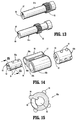
- the first needle carriage 90a defines a centrally disposed keyed central opening 92 that receives the distal portion 82b of the first drive shaft 81a.
- the distal portion 82b of the first drive shaft 81a is disposed within the keyed central opening 92 of the first needle carriage 90a and engages the first needle carriage 90a to rotate the first needle carriage 90a in response to rotation of the first drive shaft 81a.
- the collar 83 of the first drive shaft 81a is has a diameter larger than the central opening 92 of the first needle carriage 90a to prevent the first needle carriage 90a from sliding proximally over the collar 83.
- the first needle carriage 90a also defines a suture passage 93 that extends in a direction parallel to the longitudinal axis of the first needle carriage 90a and is positioned radially outward from the central opening 92.
- the outer surface of the first needle carriage 90a includes a plurality of nubs 94 extending radially outward from the outer surface of the first needle carriage 90a.
- Each of the plurality of nubs 94 are sized to be received within drive grooves 19 ( FIG. 5 ) defined along the inner surface of the drive channels 17 ( FIG. 5 ) of the elongated housing portion 16 of the housing 12.
- the plurality of nubs 94 are disposed in four longitudinal rows radially spaced 90° apart about the outer surface of the first needle carriage 90a. It is contemplated that the plurality of nubs 94 may be disposed in a range of 2 to 8 longitudinal rows equally spaced about the outer surface of the first needle carriage 90a.
- Each of the plurality of nubs 94 in a respective longitudinal row of the plurality of nubs 94 is longitudinally spaced apart from one another such that each of the nubs 94 is received within one of the drive grooves 19. It is within the scope of this disclosure that the plurality of nubs 94 may be disposed about the outer surface of the first needle carriage 90a in a helical pattern such that each of the plurality of nubs 94 is disposed within the drive grooves 19 without the plurality of nubs 94 forming longitudinal rows about the outer surface of the first needle carriage 90a. As detailed below, when the first needle carriage 90a rotates in response to rotation of the first drive shaft 81a, the plurality of nubs 94 translate within the drive grooves 19 to longitudinally translate the first needle carriage 90a along the first drive shaft 81a.
- the second needle carriage 90b is substantially similar to the first needle carriage 90a with like features labeled in a similar manner, as such, only the differences will be detailed herein.
- the keyed central opening 92 of the second needle carriage 90b is slidably disposed over the distal portion 82b of the second drive shaft 81b.
- the distal portion 82b of the second drive shaft 81b is rotationally fixed within the keyed central opening 92 of the second needle carriage 90b such that rotation of the second drive shaft 81b causes rotation of the second needle carriage 90b.
- a knife carriage 96 includes a central portion 97 disposed between first and second guide cylinders 98a, 98b.
- the first guide cylinder 98a defines a first rod opening 99a having a diameter greater than a diameter of the first drive shaft 81a ( FIG. 6 ).
- the first drive shaft 81a slidably passes through the first rod opening 99a as detailed below.
- the outer diameter of the first guide cylinder 98a is sized to translate within the drive channel 17 ( FIG. 5 ) of the elongated housing portion 16.
- the first guide cylinder 98a includes a distal face that is engaged by the first needle carriage 90a as the first needle carriage 90a is retracted within the drive channel 17 as detailed below.
- the second guide cylinder 98b defines a second rod opening 99b having a diameter greater than a diameter of a second needle 102b.
- the second needle 102b and the second drive shaft 81b slidably pass through the second rod opening 99b of the second guide cylinder 98b as detailed below.
- the outer diameter of the second guide cylinder 98b is sized to translate within the drive channel 17 ( FIG. 5 ) of the elongated housing portion 16.
- the second guide cylinder 98b incudes a proximal face that is engaged by the second needle carriage 90b as the second needle carriage 90b is advanced within the drive channel 17 as detailed below.
- the central portion 97 receives a proximal portion of the knife bars 52 to translate the knife bars 52 through the end effector 30 as the knife carriage 96 is translated within the drive channel 17.
- the proximal portions 82a of the first and second drive shafts 81a, 81b and the proximal end 79a of the articulation rod 79 are positioned within a central passage 15 ( FIG. 12 ) of the proximal housing portion 14.
- the gears 85 of the first and second sleeves 84a, 84b are positioned within the proximal housing portion 14 such that the gears 85 are engagable by a drive mechanism (e.g., drive member 20) to rotate the first and second drive shafts 81a, 81b.
- the proximal end 79a of the articulation rod extends into the central passage 15 such that the proximal end 79a is engagable with a drive mechanism to articulate the end effector 30 ( FIG. 11 ) relative to the elongated housing portion 16 as detailed above.
- the sutures 100a, 100b extend proximally from the suture passages 87 of the first and second drive sleeves 84a, 84b to a supply of suture material (not shown).
- the supply of suture material may be supported within the drive member 20, within the adapter 28 ( FIG. 1B ), or within the electromechanical handpiece 27 ( FIG. 1B ). It is also contemplated that the supply of suture material may be disposed within the loading unit 10.
- a second needle 102b has a proximal end 104 and a distal tip 106 and defines a suture channel 108 between the proximal end 104 and the distal end 106.
- the second needle 102b defines a helical shape and is positioned about the longitudinal axis of the second drive shaft 81b.
- the second drive shaft 81b passes through the center of the helical shape of the second needle 102b.
- the suture channel 108 of the second needle 102b is sized to slidably receive the second suture 100b.
- the proximal end 104 of the second needle 102b is fixed within the suture passage 93 of the second needle carriage 90b to secure the second needle 102b to the second needle carriage 90b.
- the second suture 100b passes through the suture passage 87 of the second drive sleeve 84b, through the suture passage 93 of the second needle carriage 90b, and through the suture channel 108 of the second needle 102b.
- a distal end 101 of the second suture 100b extends from the distal tip 106 of the second needle 102b.
- the first needle 102a is substantially similar to the second needle 102b with like features labeled in a similar manner, as such, only the differences will be detailed herein.
- the first needle 102a defines a helical shape and is positioned about the longitudinal axis of the first drive shaft 81a ( FIG. 18 ).
- the first drive shaft 81a passes through the center of the helical shape of the first needle 102a.
- the proximal end 104 of the first needle 102a is fixed within the suture passage 93 of the first needle carriage 90a to secure the first needle 102a to the first needle carriage 90a.
- the first suture 100a passes through the suture passage 87 of the first drive sleeve 82a, through the first guide cylinder 98a of the knife carriage 96, through the suture passage 93 of the first needle carriage 90a, and through the suture channel 108 of the first needle 102a.
- a distal end 101 of the first suture 100a extends from the distal tip 106 of the first needle 102a ( FIG. 17 ).
- the distal tip 106 forms a sharpened tip for penetrating tissue as detailed below.
- actuation of the drive mechanism 80 of the loading unit 10 is detailed in accordance with the present disclosure.
- a drive member e.g., drive member 20
- the proximal housing portion 14 FIG. 19
- the gears 85 of the first and second drive sleeves 84a, 84b FIG. 19 .
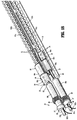
- the drive mechanism 80 is shown in a retracted position.
- the first drive rod 81a passes through the keyed opening 86 of the first drive sleeve 84a, the rod opening 99a of the first guide cylinder 98a of the knife carriage 96, and the central opening 92 ( FIG. 14 ) of the first needle carriage 90a.
- the first needle 102a extends distally from the first needle carriage 90a such that the helical shape of the first needle 102a coils around the first drive rod 81a.
- first suture 100a passes through the suture passage 87 of the first drive sleeve 84a, through the rod opening 99a of the first guide cylinder 98a, through the suture passage 93 of the first needle carriage 90a, and through the suture channel 108 ( FIG. 17 ) of the first needle 102a.
- suture passages 87, 93 of the first drive sleeve 84a and the first needle carriage 90a are radially aligned such that the first suture 100a extends in a direction that is substantially parallel to the longitudinal axis of the first drive shaft 81a between the first drive sleeve 84a and the first needle carriage 90a.
- suture passages 87, 93 are radially positioned such that the suture 100a passes over the collar 83 of the first drive shaft 81a and through the rod opening 99a of the first guide cylinder 98a without interference as the first drive shaft 81a is rotated as detailed below.
- the second drive rod 81b passes through the keyed opening 86 of the second drive sleeve 84b, the central opening 92 of the second needle carriage 90b, and the rod opening 99b ( FIG. 22 ) of the second guide cylinder 98b of the knife carriage 96.
- the second needle 102b distally extends from the second needle carriage 90a and through the rod opening 99b ( FIG. 14 ) of the second guide cylinder 98b such that the helical shape of the second needle 102b coils around the second drive rod 81b.
- the second suture 100b passes through the suture passage 87 of the second drive sleeve 84b, through the suture passage 93 of the second needle carriage 90b, and through the suture channel 108 ( FIG.
- the suture passages 87, 93 of the second drive sleeve 84b and the second needle carriage 90b are radially aligned such that the second suture 100b extends in a direction that is substantially parallel to the longitudinal axis of the second drive shaft 81b between the second drive sleeve 84b and the second needle carriage 90b.
- the suture passages 84, 93 are radially positioned such that the second suture 100b passes over the collar 83 without interference as the second drive shaft 81b is rotated as detailed below.
- the knife bars 52 are positioned between the first and second drive rods 81a, 81b with the proximal end of the knife bars 52 coupled to the central portion 97 of the knife carriage 96.
- the articulation rod 79 is positioned adjacent the first drive rod 81a and extends in a direction that is substantially parallel to the longitudinal axis of the first drive rod 81a. It will be appreciated that the knife bars 52 and the articulation rod 79 are spaced apart from the first and second drive rods 81a, 81b such that the knife bars 52 and the articulation rod 79 do not interfere with the rotation of the drive mechanism 80 and the first and second needles 102a, 102b.
- the knife bars 52 may support the knife carriage 96 within the drive channel 17 ( FIG. 20 ) of the elongated housing portion 16.
- the drive mechanism 80 is advanced towards an extended position by actuating drive member 20 ( FIG. 19 ) to rotate the first and second drive sleeves 84a, 84b in a clockwise direction.
- the first and second drive sleeves 84a, 84b are rotated in a clockwise direction
- the first and second drive sleeves 84a, 84b rotate the first and second drive shafts 81a, 81b in a clockwise direction to rotate the first and second needle carriages 90a, 90b in a clockwise direction.
- the plurality of nubs 94 of the first and second needle carriages 90a, 90b which are received in the grooves 19 ( FIGS. 20 and 22 ) defined in the elongated housing portion 16 translate through the grooves 19 to advance the first and second needle carriages 90a, 90b along the first and second drive shafts 81a, 81b, respectively.
- the first and second needle carriages 90a, 90b are advanced, the first and second needles 102a, 102b are rotatably advanced through the end effector 30 as detailed below.
- a distal surface of the second needle carriage 90b engages a proximal surface of the second guide channel 98b to advance the knife carriage 96 through the end effector 30.
- the knife carriage 96 advances the knife 54 through the end effector 30 as detailed below.
- the first and second needles 102a, 102b are rotatably advanced through the end effector 30 and the knife 54 is advanced through the knife slot 36 of the end effector 30.
- the upper and lower flanges 56, 58 of the knife 54 translate along the clamping channels 28 of the upper and lower jaws 32, 34 to move the upper and lower jaws 32, 34 of the end effector 30 to the closed configuration against the jaw biasing member 31 ( FIG. 6 ) and thereafter, maintain a maximum tissue gap between the upper and lower jaws 32, 34 of the end effector 30.
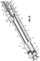
- first and second needles 102a, 102b are rotatably advanced through the end effector 30 from a retracted position ( FIG. 24 ) to an advanced position ( FIG. 25 ), the first and second needles 102a, 102b rotate through the helical path 43 ( FIGS. 26 and 30 ) defined by the wells 42 of the upper and lower jaws 32, 34 to pass the sutures 100a, 100b through tissue (not shown) between the upper and lower jaws 32, 34.
- first and second needles 102a, 102b are rotatably advanced through the end effector 30, the tips 106 of the first and second needles 102, 102b create a helical path through tissue between the first and second jaws 32, 34 and draw the first and second sutures 100a, 100b through the helical path created in the tissue.
- the blade 55 of the knife 54 is advanced through the knife slot 36 of the first and second jaws 32, 34 to sever the tissue between the first and second jaws 32, 34.
- the blade 55 of the knife 54 trails the distal tips 106 of the first and second needles 102a, 102b to allow the first and second needles 102a, 102b to secure the tissue together before the tissue is severed by the blade 55 of the knife 54.
- the blade 55 of the knife 54 trails the distal tips 106 by approximately 2.0 helical loops of the first and second needles 102a, 102b; however, it is within the scope of this disclosure that the blade 55 of the knife 54 may trail the tips 106 in a range of about 0.1 loops to about 5.5 loops of the first and second needles 102a, 102b.
- the first and second needles 102a, 102b are rotatably advanced through the end effector 30 to position the tips 106 of the first and second needles 102a, 102b at a desired position along the length of the end effector 30.
- the desired position may be reached when the distal tips 106 of the first and second needles 102a, 102b reach the last well 42 of the first and second jaws 32, 34 or when a desired length of tissue is secured together by the first and second needles 102a, 102b.
- the desired length may be in a range of about 5 mm to about 90 mm.
- the first and second needles 102a, 102b when the first and second needles 102a, 102b reach the desired position, the first and second needles 102a, 102b, are rotatably withdrawn to the retracted position ( FIG. 24 ) by actuating the drive member 20 to rotate the first and second drive sleeves 84a, 84b in a counter-clockwise direction about the longitudinal axis of the first and second drive shafts 81a, 81b, respectively.
- the first and second drive sleeves 84a, 84b rotate the first and second drive shafts 81a, 81b in a counter-clockwise direction which rotates the first and second needle carriages 90a, 90b in a counter-clockwise direction.
- the plurality of nubs 94 of the first and second needle carriages 90a, 90b which are received in the grooves 19 defined in the elongated housing portion 16 are retracted to retract the first and second needle carriages 90a, 90b along the first and second drive shafts 81a, 81b, respectively.
- the first and second needles 102a, 102b are rotatably withdrawn through the end effector 30.
- a proximal surface of the first needle carriage 90a engages a distal surface of the first guide channel 98a to retract the knife carriage 96 through the end effector 30 to retract the knife bars 52 and the knife 54 through the end effector 30.
- the upper and lower flanges 56, 58 slide distally along the clamping channels 38 of the upper and lower jaws 32, 34 ( FIG. 28 ).
- the jaw biasing member 31 urges the upper and lower jaws 32, 34 towards the open configuration.
- the first and second sutures 100a, 100b are pulled from within the suture channels 108 of the first and second needles 102a, 102b. More specifically, the sutures 100a, 100b are prevented from being withdrawn from the tissue by retaining features (e.g., barbs 101a ( FIG. 17 )) formed on each of the sutures 100a, 100b.
- the retaining features engage tissue in contact with the sutures 100a, 100b to prevent the sutures 100a, 100b from being withdrawn from the tissue.
- the first and second sutures 100a, 100b which are substantially disposed within the suture channels 108 of the first and second needles 102a, 102b, are drawn through the helical path created in the tissue between the first and second jaws 32, 34.
- the distal ends 101 ( FIG. 17 ) of the first and second sutures 100a, 100b extend from the distal tips 106 of the first and second needles 102a, 102b.
- the retaining features e.g., barbs 101a
- the retaining features prevent the sutures 100a, 100b from being withdrawn through tissue with the first and second needles 102a, 102b.
- additional retaining features of the sutures 100a, 100b engage tissue and secure the sutures 100a, 100b to tissue.
- Suitable retaining features of the sutures 100a, 100b are disclosed in U.S. Patent Nos. 8,100,940 and 8,795,332 and U.S. Patent Application No.
- sutures are commercially available from Covidien LP and sold under the name V-LocTM wound closure devices.
- the suture cutting mechanism 60 is actuated to cut the sutures 102a, 102b to leave a portion of the sutures 102a, 102b within the tissue to secure the tissue together.
- a portion of the first and second sutures 102a, 102b remains within the suture channels 108 of the first and second needles 102a, 102b with a distal end 101 extending from the distal tips 106 of the first and second needles 102a, 102b such that the suturing device 10 may be reused to secure additional tissue together.
- first and second needles 102a, 102b As the first and second needles 102a, 102b are advanced, a portion of the first and second needles 102a, 102b rotates about the finger 66 of the suture cutter 62 between the cutting surface 67 of the finger 66 and an anvil 49 of the lower jaw 32. Then, as the first and second needles 102a, 102b are retracted, a portion of the first and second sutures 100a, 100b that is positioned between the cutting surface 67 of the suture cutter 62 and the anvil 49 of the lower jaw 32 is exposed.
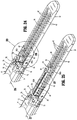
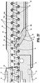
- the cutting cams 59 disposed on the lower flange 58 of the knife 54 engages the cam 68 of the suture cutter 62 to move suture cutter 62 proximally from a distal position ( FIG. 27 ) to a proximal position ( FIG. 28-30 ).
- the cutting surface 67 of the finger 66 is in contact with the anvil 49 of the lower jaw 32 such that the suture cutter 62 cuts a portion of the sutures 100a, 100b positioned between the cutting surface 67 and the anvil 69.
- the finger 66 of the suture cutter 62 is positioned below an upper surface of the anvil 49 of the lower jaw 32 to prevent the suture cutter 62 from prematurely cutting the sutures 100a, 100b.
- the cutting cam 59 engages a camming surface 68a of the suture cutter 62 to lift (move the suture cutter 62 towards the second jaw 34) such that the finger 66 is positioned above the upper surface of the anvil 69 to allow the cutting surface 67 to contact the anvil 49 of the lower jaw 32 and sever the suture 100a.
- the finger 66 of the suture cutter 62 engages the anvil 49 of the lower jaw 32.
- the suture cutter 62 is biased towards the distal position by the cutter biasing member 65 ( FIG. 26 ) that is coupled to the biasing flange 64 of the suture cutter 62.
- the biasing member 65 is extended by the interaction of the cutting cam 59 of the knife 54 with the cam 68 of the suture cutter 62.
Landscapes
- Health & Medical Sciences (AREA)
- Life Sciences & Earth Sciences (AREA)
- Surgery (AREA)
- Heart & Thoracic Surgery (AREA)
- Engineering & Computer Science (AREA)
- Biomedical Technology (AREA)
- Nuclear Medicine, Radiotherapy & Molecular Imaging (AREA)
- Medical Informatics (AREA)
- Molecular Biology (AREA)
- Animal Behavior & Ethology (AREA)
- General Health & Medical Sciences (AREA)
- Public Health (AREA)
- Veterinary Medicine (AREA)
- Surgical Instruments (AREA)
Applications Claiming Priority (2)
| Application Number | Priority Date | Filing Date | Title |
|---|---|---|---|
| US201562166983P | 2015-05-27 | 2015-05-27 | |
| US15/150,618 US10092286B2 (en) | 2015-05-27 | 2016-05-10 | Suturing loading unit |
Publications (3)
| Publication Number | Publication Date |
|---|---|
| EP3097864A2 true EP3097864A2 (fr) | 2016-11-30 |
| EP3097864A3 EP3097864A3 (fr) | 2017-03-22 |
| EP3097864B1 EP3097864B1 (fr) | 2018-11-07 |
Family
ID=56081337
Family Applications (1)
| Application Number | Title | Priority Date | Filing Date |
|---|---|---|---|
| EP16171486.0A Not-in-force EP3097864B1 (fr) | 2015-05-27 | 2016-05-26 | Unité de chargement de suture |
Country Status (4)
| Country | Link |
|---|---|
| US (2) | US10092286B2 (fr) |
| EP (1) | EP3097864B1 (fr) |
| CN (1) | CN106175855B (fr) |
| CA (1) | CA2930247A1 (fr) |
Cited By (2)
| Publication number | Priority date | Publication date | Assignee | Title |
|---|---|---|---|---|
| EP3636165A1 (fr) * | 2018-10-11 | 2020-04-15 | Covidien LP | Dispositif de suture en bourse laparoscopique |
| WO2020092656A1 (fr) | 2018-10-30 | 2020-05-07 | Health Research, Inc. | Dispositifs et procédés de suture automatique |
Families Citing this family (9)
| Publication number | Priority date | Publication date | Assignee | Title |
|---|---|---|---|---|
| US10092286B2 (en) | 2015-05-27 | 2018-10-09 | Covidien Lp | Suturing loading unit |
| SE543080C2 (en) * | 2018-05-25 | 2020-10-06 | Suturion Ab | A suturing device with needle-transfer of a double-ended needle |
| CN109171852B (zh) * | 2018-09-20 | 2024-01-30 | 广州高志恒达科技有限公司 | 一种切口内壁组织缝合器 |
| US12336702B2 (en) | 2020-03-03 | 2025-06-24 | Wright Medical Technology, Inc. | Auto-sutured allograft |
| CA3186625A1 (fr) * | 2020-06-07 | 2021-12-16 | Health Research, Inc. | Dispositif articule pour suture automatique et procede d'un tel dispositif |
| US11382615B2 (en) * | 2020-06-15 | 2022-07-12 | Blake Ariel Feldmar | Automatic suture device to reduce bleeding in gastric bypass surgery |
| EP4346629A1 (fr) * | 2021-05-25 | 2024-04-10 | Edwards Lifesciences Corporation | Dispositifs transcathéters pour réparer un feuillet d'une valve cardiaque d'un sujet |
| CN117838336B (zh) * | 2024-01-25 | 2024-08-27 | 瀚芯医疗科技(深圳)有限公司 | 组织限位装置 |
| CN119423964B (zh) * | 2025-01-09 | 2025-05-16 | 上海交通大学医学院附属瑞金医院 | 一种瓣叶切割装置及应用 |
Citations (4)
| Publication number | Priority date | Publication date | Assignee | Title |
|---|---|---|---|---|
| US20040088003A1 (en) | 2002-09-30 | 2004-05-06 | Leung Jeffrey C. | Barbed suture in combination with surgical needle |
| US8100940B2 (en) | 2002-09-30 | 2012-01-24 | Quill Medical, Inc. | Barb configurations for barbed sutures |
| US20120253329A1 (en) | 2007-09-21 | 2012-10-04 | Michael Zemlok | Hand held surgical handle assembly, surgical adapters for use between surgical handle assembly and surgical end effectors, and methods of use |
| US8795332B2 (en) | 2002-09-30 | 2014-08-05 | Ethicon, Inc. | Barbed sutures |
Family Cites Families (333)
| Publication number | Priority date | Publication date | Assignee | Title |
|---|---|---|---|---|
| DE1423881U (fr) | ||||
| US3123077A (en) | 1964-03-03 | Surgical suture | ||
| US1822330A (en) | 1930-01-13 | 1931-09-08 | Ainslie George | Suturing instrument |
| US1982207A (en) | 1933-12-29 | 1934-11-27 | Henry D Furniss | Clamping instrument and process of using the same |
| US2033039A (en) | 1935-05-22 | 1936-03-03 | Arthur A Limpert | Double point rotary pin |
| US2327353A (en) | 1940-12-12 | 1943-08-24 | Singer Mfg Co | Instrument for suturing |
| US2391792A (en) | 1942-01-23 | 1945-12-25 | Johns Manville | Wall construction and fastener therefor |
| US2832129A (en) | 1954-01-11 | 1958-04-29 | Heli Coil Corp | Tool for inserting wire coil screw threads |
| US3073311A (en) | 1958-11-07 | 1963-01-15 | Nat Res Dev | Sewing device |
| US3687138A (en) | 1970-08-17 | 1972-08-29 | Robert K Jarvik | Repeating ligature gun |
| SU715082A1 (ru) | 1977-01-24 | 1980-02-15 | Всесоюзный научно-исследовательский и испытательный институт медицинской техники | Хирургический сшивающий аппарат |
| US4236470A (en) | 1979-01-17 | 1980-12-02 | Stenson Thomas K | Portable stitching device |
| JPS571332A (en) | 1980-06-06 | 1982-01-06 | Janome Sewing Machine Co Ltd | Catching of needle yarn loop of operation suturing device |
| AU5814786A (en) | 1986-02-24 | 1987-09-09 | Optical Radiation Corp. | Magnifying stereoscopic viewer |
| US4679572A (en) | 1986-03-11 | 1987-07-14 | Intermedics, Inc. | Low threshold cardiac pacing electrodes |
| DK163713C (da) | 1987-09-02 | 1992-09-07 | Ole Gyring Nieben | Anordning til anbringelse af et partielt kateter i et legemshulrum |
| US4890615B1 (en) | 1987-11-05 | 1993-11-16 | Linvatec Corporation | Arthroscopic suturing instrument |
| US4930674A (en) | 1989-02-24 | 1990-06-05 | Abiomed, Inc. | Surgical stapler |
| US5053047A (en) | 1989-05-16 | 1991-10-01 | Inbae Yoon | Suture devices particularly useful in endoscopic surgery and methods of suturing |
| US4935027A (en) | 1989-08-21 | 1990-06-19 | Inbae Yoon | Surgical suture instrument with remotely controllable suture material advancement |
| US5358498A (en) | 1990-02-01 | 1994-10-25 | Deknatel Technology Corporation, Inc. | Needled suture |
| US5439478A (en) | 1990-05-10 | 1995-08-08 | Symbiosis Corporation | Steerable flexible microsurgical instrument with rotatable clevis |
| US5037433A (en) | 1990-05-17 | 1991-08-06 | Wilk Peter J | Endoscopic suturing device and related method and suture |
| US5100430A (en) | 1990-08-31 | 1992-03-31 | Cordis Corporation | Biopsy forceps device having a ball and socket flexible coupling |
| US5080663A (en) | 1990-09-26 | 1992-01-14 | Univerity College London | Sewing device |
| US5042707A (en) | 1990-10-16 | 1991-08-27 | Taheri Syde A | Intravascular stapler, and method of operating same |
| US5209747A (en) | 1990-12-13 | 1993-05-11 | Knoepfler Dennis J | Adjustable angle medical forceps |
| DK166600B1 (da) | 1991-01-17 | 1993-06-21 | Therkel Bisgaard | Vaerktoejssaet til brug ved suturering i dybe operationsaabninger eller legemshulrum |
| US5100421A (en) | 1991-02-05 | 1992-03-31 | Cyprus Endosurgical Tools, Inc. | Christoudias curved needle suture assembly |
| DE4104755A1 (de) | 1991-02-15 | 1992-08-20 | Heidmueller Harald | Chirurgisches instrument |
| US5405352A (en) | 1991-04-09 | 1995-04-11 | Weston; Peter V. | Suture knot, method for its formation and use, and knot forming apparatus |
| WO1993001750A1 (fr) | 1991-07-23 | 1993-02-04 | Kernforschungszentrum Karlsruhe Gmbh | Instrument de suture chirurgical |
| GB2260704B (en) | 1991-09-30 | 1995-08-23 | Philip Richardson | Suturing apparatus |
| US5443198A (en) | 1991-10-18 | 1995-08-22 | United States Surgical Corporation | Surgical fastener applying apparatus |
| US5300082A (en) | 1992-01-08 | 1994-04-05 | Sharpe Endosurgical Corporation | Endoneedle holder surgical instrument |
| ATE215430T1 (de) | 1992-01-21 | 2002-04-15 | Stanford Res Inst Int | Endoskopisches chirurgisches instrument |
| US6963792B1 (en) | 1992-01-21 | 2005-11-08 | Sri International | Surgical method |
| US5271543A (en) | 1992-02-07 | 1993-12-21 | Ethicon, Inc. | Surgical anastomosis stapling instrument with flexible support shaft and anvil adjusting mechanism |
| US5163343A (en) | 1992-02-21 | 1992-11-17 | Gish Donald A | System for fastening plies of fabric |
| US5417203A (en) | 1992-04-23 | 1995-05-23 | United States Surgical Corporation | Articulating endoscopic surgical apparatus |
| US5342389A (en) | 1992-04-28 | 1994-08-30 | Habley Medical Technology Corporation | Tissue manipulator |
| US5188636A (en) | 1992-05-07 | 1993-02-23 | Ethicon, Inc. | Purse string suture instrument |
| US5437266A (en) | 1992-07-02 | 1995-08-01 | Mcpherson; William | Coil screw surgical retractor |
| US5308353A (en) | 1992-08-31 | 1994-05-03 | Merrimac Industries, Inc. | Surgical suturing device |
| US6010515A (en) | 1993-09-03 | 2000-01-04 | University College London | Device for use in tying knots |
| US6048351A (en) | 1992-09-04 | 2000-04-11 | Scimed Life Systems, Inc. | Transvaginal suturing system |
| US5381943A (en) | 1992-10-09 | 1995-01-17 | Ethicon, Inc. | Endoscopic surgical stapling instrument with pivotable and rotatable staple cartridge |
| US5374277A (en) | 1992-10-09 | 1994-12-20 | Ethicon, Inc. | Surgical instrument |
| US5601224A (en) | 1992-10-09 | 1997-02-11 | Ethicon, Inc. | Surgical instrument |
| US5330502A (en) | 1992-10-09 | 1994-07-19 | Ethicon, Inc. | Rotational endoscopic mechanism with jointed drive mechanism |
| US5350391A (en) | 1992-10-19 | 1994-09-27 | Benedetto Iacovelli | Laparoscopic instruments |
| US5309927A (en) | 1992-10-22 | 1994-05-10 | Ethicon, Inc. | Circular stapler tissue retention spring method |
| DE4304353A1 (de) | 1992-10-24 | 1994-04-28 | Helmut Dipl Ing Wurster | Endoskopisches Nähgerät |
| US5540703A (en) | 1993-01-06 | 1996-07-30 | Smith & Nephew Richards Inc. | Knotted cable attachment apparatus formed of braided polymeric fibers |
| US5540706A (en) | 1993-01-25 | 1996-07-30 | Aust; Gilbert M. | Surgical instrument |
| CA2114330A1 (fr) | 1993-01-29 | 1994-07-30 | Smith & Nephew Endoscopy, Inc. | Instrument rotatif de forme courbe |
| US5356424A (en) | 1993-02-05 | 1994-10-18 | American Cyanamid Co. | Laparoscopic suturing device |
| US5336229A (en) | 1993-02-09 | 1994-08-09 | Laparomed Corporation | Dual ligating and dividing apparatus |
| US5456145A (en) | 1993-02-16 | 1995-10-10 | Kato Spring Works Company, Ltd. | Installation tool for tangless helically coiled insert |
| US5643294A (en) | 1993-03-01 | 1997-07-01 | United States Surgical Corporation | Surgical apparatus having an increased range of operability |
| US5374275A (en) | 1993-03-25 | 1994-12-20 | Synvasive Technology, Inc. | Surgical suturing device and method of use |
| DE4310555C1 (de) | 1993-03-31 | 1993-12-09 | Strobel & Soehne Gmbh & Co J | Chirurgische Nähmaschine |
| US5391176A (en) | 1993-06-02 | 1995-02-21 | General Surgical Innovations, Inc. | Surgical instrument for tying a knot in a length of suture at a remote location |
| US5472446A (en) | 1993-06-02 | 1995-12-05 | De La Torre; Roger A. | Surgical instrument for tying a knot in a length of suture at a remote location |
| US5527323A (en) | 1993-06-02 | 1996-06-18 | General Surgical Innovations, Inc. | Surgical instrument for tying a knot in a length of suture at a remote location |
| US5681331A (en) | 1993-06-02 | 1997-10-28 | De La Torre; Roger A. | Surgical instrument for tying a knot in a length of suture at a remote location |
| JPH09501333A (ja) | 1993-07-21 | 1997-02-10 | エイチ. クリーマン,チャールズ | 内視鏡検査及び外科手術用の外科的器具 |
| US5582617A (en) | 1993-07-21 | 1996-12-10 | Charles H. Klieman | Surgical instrument for endoscopic and general surgery |
| US5827323A (en) | 1993-07-21 | 1998-10-27 | Charles H. Klieman | Surgical instrument for endoscopic and general surgery |
| US5792165A (en) | 1993-07-21 | 1998-08-11 | Charles H. Klieman | Endoscopic instrument with detachable end effector |
| CA2124651C (fr) | 1993-08-20 | 2004-09-28 | David T. Green | Appareil et methode pour mettre en place et ajuster un dispositif d'ancrage de structures internes |
| CA2133377C (fr) | 1993-10-08 | 2004-09-14 | H. Jonathan Tovey | Appareil de suture chirurgicale dote d'un mecanisme de chargement |
| US5674230A (en) | 1993-10-08 | 1997-10-07 | United States Surgical Corporation | Surgical suturing apparatus with locking mechanisms |
| US5478344A (en) | 1993-10-08 | 1995-12-26 | United States Surgical Corporation | Surgical suturing apparatus with loading mechanism |
| US5527322A (en) | 1993-11-08 | 1996-06-18 | Perclose, Inc. | Device and method for suturing of internal puncture sites |
| US5643293A (en) | 1993-12-29 | 1997-07-01 | Olympus Optical Co., Ltd. | Suturing instrument |
| AU1011595A (en) | 1994-01-13 | 1995-07-20 | Ethicon Inc. | Spiral surgical tack |
| GB9405790D0 (en) | 1994-03-23 | 1994-05-11 | Univ London | Sewing device |
| US5454827A (en) | 1994-05-24 | 1995-10-03 | Aust; Gilbert M. | Surgical instrument |
| US5766196A (en) | 1994-06-06 | 1998-06-16 | Tnco, Inc. | Surgical instrument with steerable distal end |
| DE4423881C1 (de) | 1994-07-07 | 1995-10-26 | Karlsruhe Forschzent | Chirurgisches Nähgerät |
| US5582616A (en) | 1994-08-05 | 1996-12-10 | Origin Medsystems, Inc. | Surgical helical fastener with applicator |
| US5938668A (en) | 1994-10-07 | 1999-08-17 | United States Surgical | Surgical suturing apparatus |
| US5480406A (en) | 1994-10-07 | 1996-01-02 | United States Surgical Corporation | Method of employing surgical suturing apparatus to tie knots |
| US5571090A (en) | 1994-10-07 | 1996-11-05 | United States Surgical Corporation | Vascular suturing apparatus |
| CA2157744C (fr) | 1994-10-07 | 2005-08-23 | Charles R. Sherts | Appareil endoscopique pour suture de tissu vasculaire |
| US5752973A (en) | 1994-10-18 | 1998-05-19 | Archimedes Surgical, Inc. | Endoscopic surgical gripping instrument with universal joint jaw coupler |
| US5549637A (en) | 1994-11-10 | 1996-08-27 | Crainich; Lawrence | Articulated medical instrument |
| US5814062A (en) | 1994-12-22 | 1998-09-29 | Target Therapeutics, Inc. | Implant delivery assembly with expandable coupling/decoupling mechanism |
| JP3798838B2 (ja) | 1995-01-20 | 2006-07-19 | オリンパス株式会社 | 結紮装置 |
| US5715832A (en) | 1995-02-28 | 1998-02-10 | Boston Scientific Corporation | Deflectable biopsy catheter |
| US5573286A (en) | 1995-03-15 | 1996-11-12 | Rogozinski; Chaim | Knot |
| US5575799A (en) | 1995-03-30 | 1996-11-19 | United States Surgical Corporation | Articulating surgical apparatus |
| US5562686A (en) | 1995-04-19 | 1996-10-08 | United States Surgical Corporation | Apparaus and method for suturing body tissue |
| US5630825A (en) | 1995-04-27 | 1997-05-20 | De La Torre; Roger A. | Magazine for loading a needle onto a stitching instrument and for loading a length of suture onto a suture dispensing instrument |
| US5755729A (en) | 1995-04-27 | 1998-05-26 | General Surgical Innovations, Inc. | Magazine for loading a needle and a length of suture onto a surgical instrument |
| US5730747A (en) | 1995-06-07 | 1998-03-24 | Smith & Nephew, Inc. | Suture passing forceps |
| WO1997001368A1 (fr) | 1995-06-26 | 1997-01-16 | Trimedyne, Inc. | Dispositif de liberation d'element therapeutique |
| US5632751A (en) | 1995-07-28 | 1997-05-27 | Piraka; Hadi A. | Surgical suturing device |
| US5662683A (en) | 1995-08-22 | 1997-09-02 | Ortho Helix Limited | Open helical organic tissue anchor and method of facilitating healing |
| US5797927A (en) | 1995-09-22 | 1998-08-25 | Yoon; Inbae | Combined tissue clamping and suturing instrument |
| US5941442A (en) | 1995-10-27 | 1999-08-24 | United States Surgical | Surgical stapler |
| JPH09135837A (ja) | 1995-11-13 | 1997-05-27 | Yasumasa Onuki | 結紮縫合装置 |
| US5762069A (en) | 1995-12-29 | 1998-06-09 | Akos Biomedical, Inc. | Multiple sample biopsy forceps |
| US5860992A (en) | 1996-01-31 | 1999-01-19 | Heartport, Inc. | Endoscopic suturing devices and methods |
| US5797537A (en) | 1996-02-20 | 1998-08-25 | Richard-Allan Medical Industries, Inc. | Articulated surgical instrument with improved firing mechanism |
| US5911727A (en) | 1996-02-20 | 1999-06-15 | Cardiothoracic Systems, Inc. | Stitcher |
| US5782844A (en) | 1996-03-05 | 1998-07-21 | Inbae Yoon | Suture spring device applicator |
| US5810851A (en) | 1996-03-05 | 1998-09-22 | Yoon; Inbae | Suture spring device |
| US5810240A (en) | 1996-03-15 | 1998-09-22 | United States Surgical Corporation | Surgical fastener applying device |
| US5788710A (en) | 1996-04-30 | 1998-08-04 | Boston Scientific Corporation | Calculus removal |
| US6119913A (en) | 1996-06-14 | 2000-09-19 | Boston Scientific Corporation | Endoscopic stapler |
| US5702408A (en) | 1996-07-17 | 1997-12-30 | Ethicon Endo-Surgery, Inc. | Articulating surgical instrument |
| US6984241B2 (en) | 1996-09-13 | 2006-01-10 | Tendon Technology, Ltd. | Apparatus and methods for tendon or ligament repair |
| US5865836A (en) | 1996-09-20 | 1999-02-02 | United States Surgical Corporation | Needle-suture combination |
| WO1998011814A2 (fr) | 1996-09-20 | 1998-03-26 | United States Surgical Corporation | Dispositif d'application d'agrafes a spirales et procede de retrait |
| US5830221A (en) | 1996-09-20 | 1998-11-03 | United States Surgical Corporation | Coil fastener applier |
| US5814054A (en) | 1996-09-23 | 1998-09-29 | Symbiosis Corporation | Automatic needle-passer suturing instrument |
| US6258119B1 (en) | 1996-11-07 | 2001-07-10 | Myocardial Stents, Inc. | Implant device for trans myocardial revascularization |
| US5715942A (en) | 1996-11-15 | 1998-02-10 | Li Medical Technologies, Inc. | Package and holder for suture anchor with sutures and surgical needles attacked |
| US5972001A (en) | 1996-11-25 | 1999-10-26 | Yoon; Inbae | Method of ligating anatomical tissue with a suture spring device |
| US5993466A (en) | 1997-06-17 | 1999-11-30 | Yoon; Inbae | Suturing instrument with multiple rotatably mounted spreadable needle holders |
| US5957937A (en) | 1996-11-27 | 1999-09-28 | Yoon; Inbae | Suturing instrument with spreadable needle holder mounted for arcuate movement |
| US5759188A (en) | 1996-11-27 | 1998-06-02 | Yoon; Inbae | Suturing instrument with rotatably mounted needle driver and catcher |
| US5984932A (en) | 1996-11-27 | 1999-11-16 | Yoon; Inbae | Suturing instrument with one or more spreadable needle holders mounted for arcuate movement |
| US5993467A (en) | 1996-11-27 | 1999-11-30 | Yoon; Inbae | Suturing instrument with rotatably mounted spreadable needle holder |
| JP3311287B2 (ja) | 1997-01-16 | 2002-08-05 | 旭光学工業株式会社 | 内視鏡観察下手術用鉗子 |
| US5928136A (en) | 1997-02-13 | 1999-07-27 | Karl Storz Gmbh & Co. | Articulated vertebra for endoscopes and method to make it |
| JP3035733B2 (ja) | 1997-03-10 | 2000-04-24 | クロバー株式会社 | 裁縫針用ホルダ、および裁縫針用ケース |
| US5947982A (en) | 1997-04-02 | 1999-09-07 | Smith & Nephew, Inc. | Suture-passing forceps |
| US5893592A (en) | 1997-04-08 | 1999-04-13 | Ethicon Endo-Surgery, Inc. | Partially tied surgical knot |
| US5749898A (en) | 1997-04-08 | 1998-05-12 | Ethicon Endo-Surgery, Inc. | Suture cartridge assembly for a surgical knot |
| US5814069A (en) | 1997-04-08 | 1998-09-29 | Ethicon Endo-Surgery, Inc. | Load assist device for a suture cartridge |
| US5728109A (en) | 1997-04-08 | 1998-03-17 | Ethicon Endo-Surgery, Inc. | Surgical knot and method for its formation |
| US6126666A (en) | 1997-04-14 | 2000-10-03 | Forschungszcutrum Karlsruhe Gmbh | Device for inserting a surgical suture needle into an endoscopic suture apparatus |
| US6126665A (en) | 1997-05-01 | 2000-10-03 | Yoon; Inbae | Surgical instrument with arcuately movable offset end effectors and method of using the same |
| US6080180A (en) | 1997-05-01 | 2000-06-27 | Yoon; Inbae | Surgical instrument with rotatably mounted offset end effector and method of using the same |
| US6143005A (en) | 1997-05-01 | 2000-11-07 | Yoon; Inbae | Suturing instrument with rotatably mounted offset needle holder and method of using the same |
| US6017358A (en) | 1997-05-01 | 2000-01-25 | Inbae Yoon | Surgical instrument with multiple rotatably mounted offset end effectors |
| US6004332A (en) | 1997-05-01 | 1999-12-21 | Yoon; Inbae | Suturing instrument with multiple rotatably mounted offset needle holders and method of using the same |
| US5931855A (en) | 1997-05-21 | 1999-08-03 | Frank Hoffman | Surgical methods using one-way suture |
| US5908428A (en) | 1997-05-27 | 1999-06-01 | United States Surgical Corporation | Stitching devices for heart valve replacement surgery |
| US5876412A (en) | 1997-06-06 | 1999-03-02 | Piraka; Hadi A. | Surgical suturing device |
| US5899914A (en) | 1997-06-11 | 1999-05-04 | Endius Incorporated | Surgical instrument |
| US5954731A (en) | 1997-07-29 | 1999-09-21 | Yoon; Inbae | Surgical instrument with multiple rotatably mounted spreadable end effectors |
| US5843126A (en) | 1997-08-15 | 1998-12-01 | Jameel; Irfan M. | Multiple surgical suture application |
| AT408832B (de) | 1997-09-09 | 2002-03-25 | Werner Ing Fuchs | Chirurgische nahtzange |
| US5865361A (en) | 1997-09-23 | 1999-02-02 | United States Surgical Corporation | Surgical stapling apparatus |
| US5921956A (en) | 1997-09-24 | 1999-07-13 | Smith & Nephew, Inc. | Surgical instrument |
| US6139563A (en) | 1997-09-25 | 2000-10-31 | Allegiance Corporation | Surgical device with malleable shaft |
| US5897563A (en) | 1997-10-08 | 1999-04-27 | Ethicon Endo-Surgery, Inc. | Method for using a needle holder to assist in suturing |
| US6171316B1 (en) | 1997-10-10 | 2001-01-09 | Origin Medsystems, Inc. | Endoscopic surgical instrument for rotational manipulation |
| DE19747154C1 (de) | 1997-10-24 | 1999-03-04 | Karlsruhe Forschzent | Nadeleinsetzer mit Nadelschutz |
| US6015416A (en) | 1998-02-26 | 2000-01-18 | Ethicon Endo-Surgery, Inc. | Surgical anastomosis instrument |
| US7491232B2 (en) | 1998-09-18 | 2009-02-17 | Aptus Endosystems, Inc. | Catheter-based fastener implantation apparatus and methods with implantation force resolution |
| US5947983A (en) | 1998-03-16 | 1999-09-07 | Boston Scientific Corporation | Tissue cutting and stitching device and method |
| WO1999055237A1 (fr) | 1998-04-29 | 1999-11-04 | Inbae Yoon | Instrument et procede servant a suturer un tissu anatomique et a nouer le materiau de suture |
| US6027522A (en) | 1998-06-02 | 2000-02-22 | Boston Scientific Corporation | Surgical instrument with a rotatable distal end |
| WO1999065398A1 (fr) | 1998-06-17 | 1999-12-23 | Inbae Yoon | Instrument de suture avec porte-aiguille angulaire et procede d'utilisation correspondant |
| US5906630A (en) | 1998-06-30 | 1999-05-25 | Boston Scientific Limited | Eccentric surgical forceps |
| US6786913B1 (en) | 1999-02-01 | 2004-09-07 | Onux Medical, Inc. | Surgical suturing instrument and method of use |
| US6332889B1 (en) | 1998-08-27 | 2001-12-25 | Onux Medical, Inc. | Surgical suturing instrument and method of use |
| CA2351531C (fr) | 1998-11-18 | 2007-04-24 | General Surgical Innovations, Inc. | Dispositif de fixation helicoidal et applicateur pour actes chirurgicaux |
| US7842048B2 (en) | 2006-08-18 | 2010-11-30 | Abbott Laboratories | Articulating suture device and method |
| US7001400B1 (en) | 1999-03-04 | 2006-02-21 | Abbott Laboratories | Articulating suturing device and method |
| US20040092964A1 (en) | 1999-03-04 | 2004-05-13 | Modesitt D. Bruce | Articulating suturing device and method |
| US7235087B2 (en) | 1999-03-04 | 2007-06-26 | Abbott Park | Articulating suturing device and method |
| US6071289A (en) | 1999-03-15 | 2000-06-06 | Ethicon Endo-Surgery, Inc. | Surgical device for suturing tissue |
| US6342065B1 (en) | 1999-03-17 | 2002-01-29 | Poly-Med, Inc. | High strength fibers of L-lactide copolymers ε-caprolactone and trimethylene carbonate and absorbable medical constructs thereof |
| US6051006A (en) | 1999-04-12 | 2000-04-18 | Smith & Nephew, Inc. | Suture-passing forceps |
| AU4836200A (en) | 1999-05-11 | 2000-11-21 | Zynergy Cardiovascular, Inc. | Steerable catheter |
| US6506196B1 (en) | 1999-06-22 | 2003-01-14 | Ndo Surgical, Inc. | Device and method for correction of a painful body defect |
| US6494888B1 (en) | 1999-06-22 | 2002-12-17 | Ndo Surgical, Inc. | Tissue reconfiguration |
| US6835200B2 (en) | 1999-06-22 | 2004-12-28 | Ndo Surgical. Inc. | Method and devices for tissue reconfiguration |
| US6821285B2 (en) | 1999-06-22 | 2004-11-23 | Ndo Surgical, Inc. | Tissue reconfiguration |
| US6663639B1 (en) | 1999-06-22 | 2003-12-16 | Ndo Surgical, Inc. | Methods and devices for tissue reconfiguration |
| US8287554B2 (en) | 1999-06-22 | 2012-10-16 | Ethicon Endo-Surgery, Inc. | Method and devices for tissue reconfiguration |
| FR2795301B1 (fr) | 1999-06-25 | 2001-08-31 | Prec | Instrument de chirurgie endoscopique |
| US7637905B2 (en) | 2003-01-15 | 2009-12-29 | Usgi Medical, Inc. | Endoluminal tool deployment system |
| US6596015B1 (en) | 1999-07-13 | 2003-07-22 | Loma Linda University Medical Center | Methods and apparatus for annealing sutures |
| US6527785B2 (en) | 1999-08-03 | 2003-03-04 | Onux Medical, Inc. | Surgical suturing instrument and method of use |
| US6235026B1 (en) | 1999-08-06 | 2001-05-22 | Scimed Life Systems, Inc. | Polypectomy snare instrument |
| US6517539B1 (en) | 1999-08-06 | 2003-02-11 | Scimed Life Systems, Inc. | Polypectomy snare having ability to actuate through tortuous path |
| US6626917B1 (en) * | 1999-10-26 | 2003-09-30 | H. Randall Craig | Helical suture instrument |
| US6641592B1 (en) | 1999-11-19 | 2003-11-04 | Lsi Solutions, Inc. | System for wound closure |
| JP2001157661A (ja) | 1999-12-02 | 2001-06-12 | Asahi Optical Co Ltd | 内視鏡用操作ワイヤの連結構造 |
| US6551332B1 (en) | 2000-03-31 | 2003-04-22 | Coalescent Surgical, Inc. | Multiple bias surgical fastener |
| US6533795B1 (en) | 2000-04-11 | 2003-03-18 | Opus Medical, Inc | Dual function suturing apparatus and method |
| JP3791893B2 (ja) | 2000-04-27 | 2006-06-28 | オリンパス株式会社 | 外科用処置具 |
| US7220266B2 (en) | 2000-05-19 | 2007-05-22 | C. R. Bard, Inc. | Tissue capturing and suturing device and method |
| US6743239B1 (en) | 2000-05-25 | 2004-06-01 | St. Jude Medical, Inc. | Devices with a bendable tip for medical procedures |
| GB0020263D0 (en) | 2000-08-18 | 2000-10-04 | Femcare Cyprus Ltd | Improvements in or relating to applicators |
| US6569105B1 (en) | 2000-09-14 | 2003-05-27 | Syntheon, Llc | Rotatable and deflectable biopsy forceps |
| JP4014792B2 (ja) | 2000-09-29 | 2007-11-28 | 株式会社東芝 | マニピュレータ |
| US6755843B2 (en) | 2000-09-29 | 2004-06-29 | Olympus Optical Co., Ltd. | Endoscopic suturing device |
| US6468309B1 (en) | 2000-10-05 | 2002-10-22 | Cleveland Clinic Foundation | Method and apparatus for stabilizing adjacent bones |
| US6551322B1 (en) | 2000-10-05 | 2003-04-22 | The Cleveland Clinic Foundation | Apparatus for implantation into bone |
| US6953462B2 (en) | 2000-10-05 | 2005-10-11 | The Cleveland Clinic Foundation | Apparatus for implantation into bone |
| US6533796B1 (en) | 2000-10-11 | 2003-03-18 | Lsi Solutions, Inc. | Loader for surgical suturing instrument |
| AU2002246923A1 (en) | 2000-10-20 | 2002-07-30 | Onux Medical, Inc. | Surgical suturing instrument and method of use |
| AU2002234140A1 (en) | 2000-10-20 | 2002-05-06 | Onux Medical, Inc. | Surgical suturing instrument and method of use |
| US6556857B1 (en) | 2000-10-24 | 2003-04-29 | Sdgi Holdings, Inc. | Rotation locking driver for image guided instruments |
| US6663633B1 (en) | 2000-10-25 | 2003-12-16 | Pierson, Iii Raymond H. | Helical orthopedic fixation and reduction device, insertion system, and associated methods |
| US6527774B2 (en) | 2000-11-08 | 2003-03-04 | The Cleveland Clinic Foundation | Apparatus for attaching fractured sections of bone |
| US6544265B2 (en) | 2000-11-08 | 2003-04-08 | The Cleveland Clinic Foundation | Apparatus for implantation into bone related applications |
| US6488683B2 (en) | 2000-11-08 | 2002-12-03 | Cleveland Clinic Foundation | Method and apparatus for correcting spinal deformity |
| US6551319B2 (en) | 2000-11-08 | 2003-04-22 | The Cleveland Clinic Foundation | Apparatus for implantation into bone |
| AU2002227163B2 (en) | 2000-11-13 | 2007-02-15 | Atossa Genetics, Inc. | Methods and devices for collecting and processing mammary fluid |
| US6511487B1 (en) | 2000-11-28 | 2003-01-28 | T. A. G. Medical Products Ltd. | Suturing instrument and method |
| US6716226B2 (en) | 2001-06-25 | 2004-04-06 | Inscope Development, Llc | Surgical clip |
| US6997931B2 (en) | 2001-02-02 | 2006-02-14 | Lsi Solutions, Inc. | System for endoscopic suturing |
| DE10116171B4 (de) | 2001-03-26 | 2005-06-02 | Philipp Moll | Endoskopische Nähmaschine |
| US6544274B2 (en) | 2001-05-02 | 2003-04-08 | Novare Surgical Systems, Inc. | Clamp having bendable shaft |
| US6676676B2 (en) | 2001-05-02 | 2004-01-13 | Novare Surgical Systems | Clamp having bendable shaft |
| US6997932B2 (en) | 2001-05-21 | 2006-02-14 | Boston Scientific Scimed, Inc. | Suture passer |
| US7083629B2 (en) | 2001-05-30 | 2006-08-01 | Satiety, Inc. | Overtube apparatus for insertion into a body |
| US7144401B2 (en) | 2001-06-07 | 2006-12-05 | Olympus Optical Co., Ltd. | Suturing device for endoscope |
| US6986776B2 (en) | 2001-06-28 | 2006-01-17 | Craig H Randall | Suturing apparatus, method and system |
| US6599310B2 (en) | 2001-06-29 | 2003-07-29 | Quill Medical, Inc. | Suture method |
| US7011668B2 (en) | 2001-07-23 | 2006-03-14 | Dvl Acquistion Sub, Inc. | Surgical suturing instrument and method of use |
| US6719764B1 (en) | 2001-08-24 | 2004-04-13 | Scimed Life Systems, Inc. | Forward deploying suturing device and methods of use |
| US6848152B2 (en) | 2001-08-31 | 2005-02-01 | Quill Medical, Inc. | Method of forming barbs on a suture and apparatus for performing same |
| JP3880907B2 (ja) | 2001-08-31 | 2007-02-14 | オリンパス株式会社 | 内視鏡用縫合器 |
| US20050267495A1 (en) | 2004-05-17 | 2005-12-01 | Gateway Medical, Inc. | Systems and methods for closing internal tissue defects |
| US20060052821A1 (en) | 2001-09-06 | 2006-03-09 | Ovalis, Inc. | Systems and methods for treating septal defects |
| AU2002326917A1 (en) | 2001-09-14 | 2003-04-01 | Onux Medical, Inc. | Surgical suturing instrument and method of use |
| US7244260B2 (en) | 2001-09-18 | 2007-07-17 | Kosek Medical K.K. | Apparatus for holding and arranging threads in surgical operations |
| CA2657241C (fr) | 2001-10-01 | 2011-03-01 | Depuy Mitek, Inc. | Appareil a sutures et procede |
| JP3921681B2 (ja) | 2001-10-01 | 2007-05-30 | ニプロ株式会社 | 心臓内縫合装置 |
| US20050177180A1 (en) | 2001-11-28 | 2005-08-11 | Aptus Endosystems, Inc. | Devices, systems, and methods for supporting tissue and/or structures within a hollow body organ |
| US8231639B2 (en) | 2001-11-28 | 2012-07-31 | Aptus Endosystems, Inc. | Systems and methods for attaching a prosthesis within a body lumen or hollow organ |
| JP4405262B2 (ja) | 2001-11-28 | 2010-01-27 | アプタス エンドシステムズ, インコーポレイテッド | 血管内動脈瘤修復システム |
| US6719765B2 (en) | 2001-12-03 | 2004-04-13 | Bonutti 2003 Trust-A | Magnetic suturing system and method |
| US20040193186A1 (en) | 2003-03-25 | 2004-09-30 | Kortenbach Juergen A. | Flexible housing element for a surgical tool |
| US7131978B2 (en) | 2001-12-11 | 2006-11-07 | Dvl Acquisition Sub, Inc. | Surgical suturing instrument and method of use |
| US20030116670A1 (en) | 2001-12-21 | 2003-06-26 | Gentry Dalvin Marshell | Portable Motorized Remote Controlled Hose Reel |
| US6942676B2 (en) | 2002-03-21 | 2005-09-13 | Novare Surgical Systems, Inc. | Surgical clamp pads with deflecting elements |
| US7207996B2 (en) | 2002-04-04 | 2007-04-24 | Vascular Control Systems, Inc. | Doppler directed suturing and compression device and method |
| JP3890589B2 (ja) | 2002-04-15 | 2007-03-07 | ニプロ株式会社 | 心臓内縫合装置 |
| US7229452B2 (en) | 2002-04-22 | 2007-06-12 | Tyco Healthcare Group Lp | Tack and tack applier |
| US7077850B2 (en) | 2002-05-01 | 2006-07-18 | Scimed Life Systems, Inc. | Tissue fastening devices and related insertion tools and methods |
| US7122039B2 (en) | 2002-05-01 | 2006-10-17 | Boston Scientific Scimed, Inc. | Tying knots |
| DE60311806T2 (de) | 2002-06-11 | 2007-10-31 | Tyco Healthcare Group Lp, Norwalk | Klammer zur Befestigung von Hernia-Netz |
| WO2003105701A2 (fr) | 2002-06-12 | 2003-12-24 | Scimed Life Systems, Inc. | Instruments de sutures |
| JP4373146B2 (ja) | 2002-07-11 | 2009-11-25 | オリンパス株式会社 | 内視鏡用縫合装置 |
| US6936054B2 (en) | 2002-07-22 | 2005-08-30 | Boston Scientific Scimed, Inc. | Placing sutures |
| US7041111B2 (en) | 2002-08-02 | 2006-05-09 | Boston Scientific Scimed, Inc. | Placing sutures |
| US7083630B2 (en) | 2002-08-29 | 2006-08-01 | Scimed Life Systems, Inc. | Devices and methods for fastening tissue layers |
| CA2500776A1 (fr) | 2002-10-04 | 2004-04-22 | Tyco Healthcare Group, Lp | Dispositif de suture chirurgical avec structure de mesure |
| US20040073237A1 (en) | 2002-10-08 | 2004-04-15 | Leinsing Karl R. | Surgical fastener and delivery system |
| US7087064B1 (en) | 2002-10-15 | 2006-08-08 | Advanced Cardiovascular Systems, Inc. | Apparatuses and methods for heart valve repair |
| US7833237B2 (en) | 2003-02-04 | 2010-11-16 | Lsi Solutions, Inc. | Instrument for assisting in the remote placement of tied surgical knots and trimming of suture away from the knot and method of use |
| US8187288B2 (en) | 2003-03-10 | 2012-05-29 | Boston Scientific Scimed, Inc. | Re-shapeable medical device |
| US7218972B2 (en) | 2003-04-07 | 2007-05-15 | Cardiac Pacemakers, Inc. | Extra strength suture sleeve |
| US7935128B2 (en) | 2003-05-21 | 2011-05-03 | Boston Scientific Scimed, Inc. | Remotely-reloadable suturing device |
| JP4598410B2 (ja) | 2003-05-27 | 2010-12-15 | オリンパス株式会社 | 内視鏡 |
| US7191900B2 (en) | 2003-06-03 | 2007-03-20 | Js Vascular, Inc. | Guide wire containment and dispensing apparatus |
| JP4266738B2 (ja) | 2003-07-02 | 2009-05-20 | オリンパス株式会社 | 結紮装置 |
| US6880691B2 (en) | 2003-07-07 | 2005-04-19 | Ge Medical Systems Global Technology Company, Llc | Release mechanism for enabling manual manipulation of a motorized C-arm |
| US6981628B2 (en) | 2003-07-09 | 2006-01-03 | Ethicon Endo-Surgery, Inc. | Surgical instrument with a lateral-moving articulation control |
| US7780701B1 (en) | 2003-08-13 | 2010-08-24 | Biomet Sports Medicine, Llc | Suture anchor |
| JP2007504885A (ja) | 2003-09-11 | 2007-03-08 | エヌエムティー メディカル, インコーポレイティッド | 組織を縫合するためのデバイス、システムおよび方法 |
| US7914543B2 (en) | 2003-10-14 | 2011-03-29 | Satiety, Inc. | Single fold device for tissue fixation |
| US8806973B2 (en) | 2009-12-02 | 2014-08-19 | Covidien Lp | Adapters for use between surgical handle assembly and surgical end effector |
| US8968276B2 (en) | 2007-09-21 | 2015-03-03 | Covidien Lp | Hand held surgical handle assembly, surgical adapters for use between surgical handle assembly and surgical end effectors, and methods of use |
| US20090090763A1 (en) | 2007-10-05 | 2009-04-09 | Tyco Healthcare Group Lp | Powered surgical stapling device |
| US7147650B2 (en) | 2003-10-30 | 2006-12-12 | Woojin Lee | Surgical instrument |
| US7736372B2 (en) | 2003-11-13 | 2010-06-15 | Usgi Medical, Inc. | Apparatus and methods for endoscopic suturing |
| US7731726B2 (en) | 2003-12-03 | 2010-06-08 | St. Jude Medical Puerto Rico Llc | Suture based vascular closure apparatus and method incorporating a pre-tied knot |
| US7052489B2 (en) | 2003-12-05 | 2006-05-30 | Scimed Life Systems, Inc. | Medical device with deflecting shaft and related methods of manufacture and use |
| US7361180B2 (en) | 2004-05-07 | 2008-04-22 | Usgi Medical, Inc. | Apparatus for manipulating and securing tissue |
| US7347863B2 (en) | 2004-05-07 | 2008-03-25 | Usgi Medical, Inc. | Apparatus and methods for manipulating and securing tissue |
| US7211093B2 (en) | 2004-01-14 | 2007-05-01 | Lsi Solutions, Inc. | Sew-right running stitch instrument |
| US7297104B2 (en) | 2004-03-01 | 2007-11-20 | John Vanden Hoek | Seam closure device and methods |
| JP4700384B2 (ja) | 2004-04-07 | 2011-06-15 | オリンパス株式会社 | 医療用結紮縫合装置及び医療用結紮縫合システム |
| WO2005096955A1 (fr) | 2004-04-07 | 2005-10-20 | Tze Liang Woffles Wu | Fil chirurgical |
| US8114099B2 (en) | 2004-04-27 | 2012-02-14 | Tyco Healthcare Group Lp | Absorbable anchor for hernia mesh fixation |
| US7232448B2 (en) | 2004-06-17 | 2007-06-19 | Ethicon, Inc. - Usa | Minimally invasive stitching device |
| US7468068B2 (en) | 2004-06-30 | 2008-12-23 | Alwin Kolster | Suture for wound closure, tissue approximation, tissue support, suspension and/or fixation |
| US7883519B2 (en) | 2004-07-06 | 2011-02-08 | Ran Oren | Suture manipulating instrument particularly useful with endoscopes |
| US7404509B2 (en) | 2004-07-28 | 2008-07-29 | Ethicon Endo-Surgery, Inc. | Electroactive polymer-based articulation mechanism for linear stapler |
| DE602005010442D1 (de) | 2004-08-16 | 2008-11-27 | Zimmer Spine Inc | Spiralförmige nähvorrichtung |
| EP1791476B1 (fr) | 2004-09-20 | 2015-12-23 | Endoevolution, Llc | Appareil de suture a invasivite minimale |
| US7722630B1 (en) | 2004-11-09 | 2010-05-25 | Biomet Sports Medicine, Llc | Method and apparatus for passing a suture through tissue |
| DE102004056204B3 (de) | 2004-11-18 | 2006-03-16 | Karl Storz Gmbh & Co. Kg | Endoskopische Nähmaschine |
| US9700334B2 (en) | 2004-11-23 | 2017-07-11 | Intuitive Surgical Operations, Inc. | Articulating mechanisms and link systems with torque transmission in remote manipulation of instruments and tools |
| ITRM20040599A1 (it) | 2004-12-06 | 2005-03-06 | Promoitalia Internat S R L | Filo chirurgico per operazioni di chirurgia plastica, dermatologiche, estetiche, e per suture chirurgiche. |
| US8906039B2 (en) | 2005-03-21 | 2014-12-09 | Design Standards Corporation | Suturing device |
| US8070685B2 (en) | 2005-04-15 | 2011-12-06 | Imacor Inc. | Connectorized probe for transesophageal echocardiography |
| US20060253126A1 (en) | 2005-05-04 | 2006-11-09 | Bernard Medical, Llc | Endoluminal suturing device and method |
| US7846169B2 (en) | 2005-06-13 | 2010-12-07 | Ethicon Endo-Surgery, Inc. | Adjustable vacuum chamber for a surgical suturing apparatus |
| US7766925B2 (en) | 2005-06-13 | 2010-08-03 | Ethicon Endo-Surgery, Inc. | Surgical suturing apparatus |
| US8500756B2 (en) | 2005-06-13 | 2013-08-06 | Ethicon Endo. Surgery, Inc. | Quick load mechanism for a surgical suturing apparatus |
| US7628796B2 (en) | 2005-06-13 | 2009-12-08 | Ethicon Endo-Surgery, Inc. | Surgical suturing apparatus with anti-backup system |
| US8663277B2 (en) | 2005-06-29 | 2014-03-04 | Ethicon, Inc. | Braided barbed suture |
| DE102005036329A1 (de) | 2005-07-29 | 2007-02-01 | Groz-Beckert Kg | Filznadelverpackung |
| US7883517B2 (en) | 2005-08-08 | 2011-02-08 | Abbott Laboratories | Vascular suturing device |
| US20070112385A1 (en) | 2005-11-15 | 2007-05-17 | Conlon Sean P | Expandable suture anchor |
| US20070142849A1 (en) | 2005-12-16 | 2007-06-21 | Usgi Medical, Inc. | Helical tissue manipulation instruments and methods of use |
| US7815652B2 (en) | 2006-03-21 | 2010-10-19 | Ethicon Endo-Surgery, Inc. | Surgical fastener and instrument |
| US7708747B2 (en) | 2006-04-12 | 2010-05-04 | InTailor Surgical, Inc. | Endoscopic suturing and implant system |
| US7758598B2 (en) | 2006-05-19 | 2010-07-20 | Ethicon Endo-Surgery, Inc. | Combination knotting element and suture anchor applicator |
| US7530984B2 (en) | 2006-06-05 | 2009-05-12 | Medigus Ltd. | Transgastric method for carrying out a partial fundoplication |
| US8556930B2 (en) | 2006-06-28 | 2013-10-15 | Abbott Laboratories | Vessel closure device |
| US20080039879A1 (en) | 2006-08-09 | 2008-02-14 | Chin Albert K | Devices and methods for atrial appendage exclusion |
| US7947052B2 (en) | 2006-09-15 | 2011-05-24 | Ethicon Endo-Surgery, Inc. | Suturing device with angled head |
| WO2008042423A2 (fr) | 2006-10-02 | 2008-04-10 | Hansen Medical, Inc. | systèmes de lever tridimensionnel par ultrasons |
| WO2008045333A2 (fr) | 2006-10-05 | 2008-04-17 | Tyco Healthcare Group Lp | Dispositifs de suture endoscopique souples |
| US9017345B2 (en) | 2006-10-06 | 2015-04-28 | Covidien Lp | Coil fastener applier with flexible shaft |
| US7947053B2 (en) | 2006-10-10 | 2011-05-24 | Mckay Raymond G | Suturing device and technique |
| JP5198014B2 (ja) | 2006-10-25 | 2013-05-15 | テルモ株式会社 | 医療用マニピュレータ |
| DE602007004789D1 (de) | 2006-10-25 | 2010-04-01 | Toshiba Kk | Manipulator zur medizinischen Verwendung |
| US7814630B2 (en) | 2006-11-17 | 2010-10-19 | Ethicon, Inc. | Apparatus and method for swaging needles |
| US8715270B2 (en) | 2006-12-01 | 2014-05-06 | Boston Scientific Scimed, Inc. | Multi-part instrument systems and methods |
| EP1958574B1 (fr) | 2007-02-13 | 2011-10-12 | Arthrex, Inc. | Instrument de passage de sutures |
| US8727197B2 (en) | 2007-03-15 | 2014-05-20 | Ethicon Endo-Surgery, Inc. | Staple cartridge cavity configuration with cooperative surgical staple |
| RU2328228C1 (ru) | 2007-04-11 | 2008-07-10 | Аркадий Вениаминович Дубровский | Сшивающее устройство для наложения механического обвивного шва |
| US7967842B2 (en) | 2007-06-01 | 2011-06-28 | Ethicon Endo-Surgery, Inc. | Integrated securement and closure apparatus |
| WO2008149457A1 (fr) | 2007-06-08 | 2008-12-11 | Seirin Corporation | Récipient d'emballage d'aiguille de moxibustion d'acuponcture |
| US8747436B2 (en) | 2007-06-13 | 2014-06-10 | Ethicon, Inc. | Bi-directional barbed suture |
| US8465505B2 (en) | 2011-05-06 | 2013-06-18 | Ceterix Orthopaedics, Inc. | Suture passer devices and methods |
| US7954687B2 (en) | 2007-11-06 | 2011-06-07 | Tyco Healthcare Group Lp | Coated surgical staples and an illuminated staple cartridge for a surgical stapling instrument |
| US8758391B2 (en) | 2008-02-14 | 2014-06-24 | Ethicon Endo-Surgery, Inc. | Interchangeable tools for surgical instruments |
| US8628545B2 (en) | 2008-06-13 | 2014-01-14 | Covidien Lp | Endoscopic stitching devices |
| US8500757B2 (en) * | 2009-07-28 | 2013-08-06 | Edwards Lifesciences Corporation | Surgical puncture cinch and closure system |
| US8459524B2 (en) * | 2009-08-14 | 2013-06-11 | Covidien Lp | Tissue fastening system for a medical device |
| AU2012225668A1 (en) | 2011-03-07 | 2013-10-10 | Passer Stitch, Llc | Suture passing devices and methods |
| US9017314B2 (en) | 2011-06-01 | 2015-04-28 | Covidien Lp | Surgical articulation assembly |
| US8899462B2 (en) | 2011-10-25 | 2014-12-02 | Covidien Lp | Apparatus for endoscopic procedures |
| NL1039407C2 (en) | 2012-02-27 | 2013-08-28 | Hunter Douglas Ind Bv | Architectural covering having a drive mechanism for extending and retracting a covering member between opposite first and second end positions. |
| US20130296955A1 (en) | 2012-05-02 | 2013-11-07 | Charles Haggerty | Suture device |
| WO2014162342A1 (fr) | 2013-04-01 | 2014-10-09 | テルモ株式会社 | Dispositif électrochirurgical bipolaire |
| US10092286B2 (en) | 2015-05-27 | 2018-10-09 | Covidien Lp | Suturing loading unit |
-
2016
- 2016-05-10 US US15/150,618 patent/US10092286B2/en active Active
- 2016-05-17 CA CA2930247A patent/CA2930247A1/fr not_active Abandoned
- 2016-05-26 EP EP16171486.0A patent/EP3097864B1/fr not_active Not-in-force
- 2016-05-26 CN CN201610362035.9A patent/CN106175855B/zh not_active Expired - Fee Related
-
2018
- 2018-09-04 US US16/120,483 patent/US10799234B2/en not_active Expired - Fee Related
Patent Citations (4)
| Publication number | Priority date | Publication date | Assignee | Title |
|---|---|---|---|---|
| US20040088003A1 (en) | 2002-09-30 | 2004-05-06 | Leung Jeffrey C. | Barbed suture in combination with surgical needle |
| US8100940B2 (en) | 2002-09-30 | 2012-01-24 | Quill Medical, Inc. | Barb configurations for barbed sutures |
| US8795332B2 (en) | 2002-09-30 | 2014-08-05 | Ethicon, Inc. | Barbed sutures |
| US20120253329A1 (en) | 2007-09-21 | 2012-10-04 | Michael Zemlok | Hand held surgical handle assembly, surgical adapters for use between surgical handle assembly and surgical end effectors, and methods of use |
Cited By (5)
| Publication number | Priority date | Publication date | Assignee | Title |
|---|---|---|---|---|
| EP3636165A1 (fr) * | 2018-10-11 | 2020-04-15 | Covidien LP | Dispositif de suture en bourse laparoscopique |
| US11219457B2 (en) | 2018-10-11 | 2022-01-11 | Covidien Lp | Laparoscopic purse string suture device |
| WO2020092656A1 (fr) | 2018-10-30 | 2020-05-07 | Health Research, Inc. | Dispositifs et procédés de suture automatique |
| JP2022509536A (ja) * | 2018-10-30 | 2022-01-20 | ヘルス リサーチ インコーポレイテッド | 自動縫合装置および自動縫合方法 |
| EP3873353A4 (fr) * | 2018-10-30 | 2022-08-10 | Health Research, Inc. | Dispositifs et procédés de suture automatique |
Also Published As
| Publication number | Publication date |
|---|---|
| CN106175855B (zh) | 2021-06-08 |
| US10092286B2 (en) | 2018-10-09 |
| CN106175855A (zh) | 2016-12-07 |
| CA2930247A1 (fr) | 2016-11-27 |
| US10799234B2 (en) | 2020-10-13 |
| US20180368829A1 (en) | 2018-12-27 |
| US20160345962A1 (en) | 2016-12-01 |
| EP3097864A3 (fr) | 2017-03-22 |
| EP3097864B1 (fr) | 2018-11-07 |
Similar Documents
| Publication | Publication Date | Title |
|---|---|---|
| EP3097864B1 (fr) | Unité de chargement de suture | |
| US11490893B2 (en) | Endoscopic stapler and staple | |
| DE69312385T2 (de) | Endoskopische Vorrichtung zum Schneiden | |
| US10595856B2 (en) | Stitching device with long needle delivery | |
| JP6316826B2 (ja) | 外科用切断器具 | |
| US10966708B2 (en) | Stitching end effector | |
| US5591180A (en) | Surgical suturing apparatus | |
| US10874399B2 (en) | Circular stapler with visual indicator mechanism | |
| AU2016340865B2 (en) | Endoscope cap with deflecting channels for endoscopic therapy | |
| EP1932485A1 (fr) | Dispositif d'agrafage laparoscopique | |
| US11197665B2 (en) | Needle reload device for use with endostitch device | |
| US12011158B2 (en) | Endoscopic stitching device for single hand operation | |
| US20130238000A1 (en) | Wound closure device | |
| US11771422B2 (en) | Active roller assembly for use in articulating stapler | |
| CN109199481B (zh) | 用于缝合穿刺孔的缝合组件 | |
| EP3730064A1 (fr) | Dispositif de fermeture d'incision de site d'orifice |
Legal Events
| Date | Code | Title | Description |
|---|---|---|---|
| PUAI | Public reference made under article 153(3) epc to a published international application that has entered the european phase |
Free format text: ORIGINAL CODE: 0009012 |
|
| AK | Designated contracting states |
Kind code of ref document: A2 Designated state(s): AL AT BE BG CH CY CZ DE DK EE ES FI FR GB GR HR HU IE IS IT LI LT LU LV MC MK MT NL NO PL PT RO RS SE SI SK SM TR |
|
| AX | Request for extension of the european patent |
Extension state: BA ME |
|
| PUAL | Search report despatched |
Free format text: ORIGINAL CODE: 0009013 |
|
| AK | Designated contracting states |
Kind code of ref document: A3 Designated state(s): AL AT BE BG CH CY CZ DE DK EE ES FI FR GB GR HR HU IE IS IT LI LT LU LV MC MK MT NL NO PL PT RO RS SE SI SK SM TR |
|
| AX | Request for extension of the european patent |
Extension state: BA ME |
|
| RIC1 | Information provided on ipc code assigned before grant |
Ipc: A61B 17/32 20060101ALN20170210BHEP Ipc: A61B 17/04 20060101AFI20170210BHEP Ipc: A61B 17/06 20060101ALN20170210BHEP Ipc: A61B 17/29 20060101ALN20170210BHEP Ipc: A61B 17/00 20060101ALN20170210BHEP |
|
| STAA | Information on the status of an ep patent application or granted ep patent |
Free format text: STATUS: REQUEST FOR EXAMINATION WAS MADE |
|
| 17P | Request for examination filed |
Effective date: 20170914 |
|
| RBV | Designated contracting states (corrected) |
Designated state(s): AL AT BE BG CH CY CZ DE DK EE ES FI FR GB GR HR HU IE IS IT LI LT LU LV MC MK MT NL NO PL PT RO RS SE SI SK SM TR |
|
| RIC1 | Information provided on ipc code assigned before grant |
Ipc: A61B 17/00 20060101ALN20180426BHEP Ipc: A61B 17/29 20060101ALN20180426BHEP Ipc: A61B 17/06 20060101ALN20180426BHEP Ipc: A61B 17/04 20060101AFI20180426BHEP Ipc: A61B 17/32 20060101ALN20180426BHEP |
|
| GRAP | Despatch of communication of intention to grant a patent |
Free format text: ORIGINAL CODE: EPIDOSNIGR1 |
|
| STAA | Information on the status of an ep patent application or granted ep patent |
Free format text: STATUS: GRANT OF PATENT IS INTENDED |
|
| RIC1 | Information provided on ipc code assigned before grant |
Ipc: A61B 17/04 20060101AFI20180503BHEP Ipc: A61B 17/00 20060101ALN20180503BHEP Ipc: A61B 17/32 20060101ALN20180503BHEP Ipc: A61B 17/29 20060101ALN20180503BHEP Ipc: A61B 17/06 20060101ALN20180503BHEP |
|
| INTG | Intention to grant announced |
Effective date: 20180601 |
|
| GRAS | Grant fee paid |
Free format text: ORIGINAL CODE: EPIDOSNIGR3 |
|
| GRAA | (expected) grant |
Free format text: ORIGINAL CODE: 0009210 |
|
| STAA | Information on the status of an ep patent application or granted ep patent |
Free format text: STATUS: THE PATENT HAS BEEN GRANTED |
|
| AK | Designated contracting states |
Kind code of ref document: B1 Designated state(s): AL AT BE BG CH CY CZ DE DK EE ES FI FR GB GR HR HU IE IS IT LI LT LU LV MC MK MT NL NO PL PT RO RS SE SI SK SM TR |
|
| REG | Reference to a national code |
Ref country code: GB Ref legal event code: FG4D |
|
| REG | Reference to a national code |
Ref country code: CH Ref legal event code: EP Ref country code: AT Ref legal event code: REF Ref document number: 1061143 Country of ref document: AT Kind code of ref document: T Effective date: 20181115 |
|
| REG | Reference to a national code |
Ref country code: DE Ref legal event code: R096 Ref document number: 602016006904 Country of ref document: DE |
|
| REG | Reference to a national code |
Ref country code: IE Ref legal event code: FG4D |
|
| REG | Reference to a national code |
Ref country code: NL Ref legal event code: MP Effective date: 20181107 |
|
| REG | Reference to a national code |
Ref country code: LT Ref legal event code: MG4D |
|
| REG | Reference to a national code |
Ref country code: AT Ref legal event code: MK05 Ref document number: 1061143 Country of ref document: AT Kind code of ref document: T Effective date: 20181107 |
|
| PG25 | Lapsed in a contracting state [announced via postgrant information from national office to epo] |
Ref country code: HR Free format text: LAPSE BECAUSE OF FAILURE TO SUBMIT A TRANSLATION OF THE DESCRIPTION OR TO PAY THE FEE WITHIN THE PRESCRIBED TIME-LIMIT Effective date: 20181107 Ref country code: NO Free format text: LAPSE BECAUSE OF FAILURE TO SUBMIT A TRANSLATION OF THE DESCRIPTION OR TO PAY THE FEE WITHIN THE PRESCRIBED TIME-LIMIT Effective date: 20190207 Ref country code: AT Free format text: LAPSE BECAUSE OF FAILURE TO SUBMIT A TRANSLATION OF THE DESCRIPTION OR TO PAY THE FEE WITHIN THE PRESCRIBED TIME-LIMIT Effective date: 20181107 Ref country code: FI Free format text: LAPSE BECAUSE OF FAILURE TO SUBMIT A TRANSLATION OF THE DESCRIPTION OR TO PAY THE FEE WITHIN THE PRESCRIBED TIME-LIMIT Effective date: 20181107 Ref country code: LV Free format text: LAPSE BECAUSE OF FAILURE TO SUBMIT A TRANSLATION OF THE DESCRIPTION OR TO PAY THE FEE WITHIN THE PRESCRIBED TIME-LIMIT Effective date: 20181107 Ref country code: ES Free format text: LAPSE BECAUSE OF FAILURE TO SUBMIT A TRANSLATION OF THE DESCRIPTION OR TO PAY THE FEE WITHIN THE PRESCRIBED TIME-LIMIT Effective date: 20181107 Ref country code: IS Free format text: LAPSE BECAUSE OF FAILURE TO SUBMIT A TRANSLATION OF THE DESCRIPTION OR TO PAY THE FEE WITHIN THE PRESCRIBED TIME-LIMIT Effective date: 20190307 Ref country code: BG Free format text: LAPSE BECAUSE OF FAILURE TO SUBMIT A TRANSLATION OF THE DESCRIPTION OR TO PAY THE FEE WITHIN THE PRESCRIBED TIME-LIMIT Effective date: 20190207 Ref country code: LT Free format text: LAPSE BECAUSE OF FAILURE TO SUBMIT A TRANSLATION OF THE DESCRIPTION OR TO PAY THE FEE WITHIN THE PRESCRIBED TIME-LIMIT Effective date: 20181107 |
|
| PG25 | Lapsed in a contracting state [announced via postgrant information from national office to epo] |
Ref country code: GR Free format text: LAPSE BECAUSE OF FAILURE TO SUBMIT A TRANSLATION OF THE DESCRIPTION OR TO PAY THE FEE WITHIN THE PRESCRIBED TIME-LIMIT Effective date: 20190208 Ref country code: PT Free format text: LAPSE BECAUSE OF FAILURE TO SUBMIT A TRANSLATION OF THE DESCRIPTION OR TO PAY THE FEE WITHIN THE PRESCRIBED TIME-LIMIT Effective date: 20190307 Ref country code: NL Free format text: LAPSE BECAUSE OF FAILURE TO SUBMIT A TRANSLATION OF THE DESCRIPTION OR TO PAY THE FEE WITHIN THE PRESCRIBED TIME-LIMIT Effective date: 20181107 Ref country code: RS Free format text: LAPSE BECAUSE OF FAILURE TO SUBMIT A TRANSLATION OF THE DESCRIPTION OR TO PAY THE FEE WITHIN THE PRESCRIBED TIME-LIMIT Effective date: 20181107 Ref country code: SE Free format text: LAPSE BECAUSE OF FAILURE TO SUBMIT A TRANSLATION OF THE DESCRIPTION OR TO PAY THE FEE WITHIN THE PRESCRIBED TIME-LIMIT Effective date: 20181107 Ref country code: AL Free format text: LAPSE BECAUSE OF FAILURE TO SUBMIT A TRANSLATION OF THE DESCRIPTION OR TO PAY THE FEE WITHIN THE PRESCRIBED TIME-LIMIT Effective date: 20181107 |
|
| PG25 | Lapsed in a contracting state [announced via postgrant information from national office to epo] |
Ref country code: PL Free format text: LAPSE BECAUSE OF FAILURE TO SUBMIT A TRANSLATION OF THE DESCRIPTION OR TO PAY THE FEE WITHIN THE PRESCRIBED TIME-LIMIT Effective date: 20181107 Ref country code: DK Free format text: LAPSE BECAUSE OF FAILURE TO SUBMIT A TRANSLATION OF THE DESCRIPTION OR TO PAY THE FEE WITHIN THE PRESCRIBED TIME-LIMIT Effective date: 20181107 Ref country code: CZ Free format text: LAPSE BECAUSE OF FAILURE TO SUBMIT A TRANSLATION OF THE DESCRIPTION OR TO PAY THE FEE WITHIN THE PRESCRIBED TIME-LIMIT Effective date: 20181107 Ref country code: IT Free format text: LAPSE BECAUSE OF FAILURE TO SUBMIT A TRANSLATION OF THE DESCRIPTION OR TO PAY THE FEE WITHIN THE PRESCRIBED TIME-LIMIT Effective date: 20181107 |
|
| REG | Reference to a national code |
Ref country code: DE Ref legal event code: R097 Ref document number: 602016006904 Country of ref document: DE |
|
| PG25 | Lapsed in a contracting state [announced via postgrant information from national office to epo] |
Ref country code: SK Free format text: LAPSE BECAUSE OF FAILURE TO SUBMIT A TRANSLATION OF THE DESCRIPTION OR TO PAY THE FEE WITHIN THE PRESCRIBED TIME-LIMIT Effective date: 20181107 Ref country code: SM Free format text: LAPSE BECAUSE OF FAILURE TO SUBMIT A TRANSLATION OF THE DESCRIPTION OR TO PAY THE FEE WITHIN THE PRESCRIBED TIME-LIMIT Effective date: 20181107 Ref country code: EE Free format text: LAPSE BECAUSE OF FAILURE TO SUBMIT A TRANSLATION OF THE DESCRIPTION OR TO PAY THE FEE WITHIN THE PRESCRIBED TIME-LIMIT Effective date: 20181107 Ref country code: RO Free format text: LAPSE BECAUSE OF FAILURE TO SUBMIT A TRANSLATION OF THE DESCRIPTION OR TO PAY THE FEE WITHIN THE PRESCRIBED TIME-LIMIT Effective date: 20181107 |
|
| PLBE | No opposition filed within time limit |
Free format text: ORIGINAL CODE: 0009261 |
|
| STAA | Information on the status of an ep patent application or granted ep patent |
Free format text: STATUS: NO OPPOSITION FILED WITHIN TIME LIMIT |
|
| 26N | No opposition filed |
Effective date: 20190808 |
|
| PG25 | Lapsed in a contracting state [announced via postgrant information from national office to epo] |
Ref country code: SI Free format text: LAPSE BECAUSE OF FAILURE TO SUBMIT A TRANSLATION OF THE DESCRIPTION OR TO PAY THE FEE WITHIN THE PRESCRIBED TIME-LIMIT Effective date: 20181107 |
|
| REG | Reference to a national code |
Ref country code: CH Ref legal event code: PL |
|
| PG25 | Lapsed in a contracting state [announced via postgrant information from national office to epo] |
Ref country code: MC Free format text: LAPSE BECAUSE OF FAILURE TO SUBMIT A TRANSLATION OF THE DESCRIPTION OR TO PAY THE FEE WITHIN THE PRESCRIBED TIME-LIMIT Effective date: 20181107 Ref country code: CH Free format text: LAPSE BECAUSE OF NON-PAYMENT OF DUE FEES Effective date: 20190531 Ref country code: LI Free format text: LAPSE BECAUSE OF NON-PAYMENT OF DUE FEES Effective date: 20190531 |
|
| REG | Reference to a national code |
Ref country code: BE Ref legal event code: MM Effective date: 20190531 |
|
| PG25 | Lapsed in a contracting state [announced via postgrant information from national office to epo] |
Ref country code: LU Free format text: LAPSE BECAUSE OF NON-PAYMENT OF DUE FEES Effective date: 20190526 |
|
| PG25 | Lapsed in a contracting state [announced via postgrant information from national office to epo] |
Ref country code: TR Free format text: LAPSE BECAUSE OF FAILURE TO SUBMIT A TRANSLATION OF THE DESCRIPTION OR TO PAY THE FEE WITHIN THE PRESCRIBED TIME-LIMIT Effective date: 20181107 |
|
| PG25 | Lapsed in a contracting state [announced via postgrant information from national office to epo] |
Ref country code: BE Free format text: LAPSE BECAUSE OF NON-PAYMENT OF DUE FEES Effective date: 20190531 |
|
| PGFP | Annual fee paid to national office [announced via postgrant information from national office to epo] |
Ref country code: IE Payment date: 20200422 Year of fee payment: 5 |
|
| PG25 | Lapsed in a contracting state [announced via postgrant information from national office to epo] |
Ref country code: CY Free format text: LAPSE BECAUSE OF FAILURE TO SUBMIT A TRANSLATION OF THE DESCRIPTION OR TO PAY THE FEE WITHIN THE PRESCRIBED TIME-LIMIT Effective date: 20181107 |
|
| PG25 | Lapsed in a contracting state [announced via postgrant information from national office to epo] |
Ref country code: MT Free format text: LAPSE BECAUSE OF FAILURE TO SUBMIT A TRANSLATION OF THE DESCRIPTION OR TO PAY THE FEE WITHIN THE PRESCRIBED TIME-LIMIT Effective date: 20181107 Ref country code: HU Free format text: LAPSE BECAUSE OF FAILURE TO SUBMIT A TRANSLATION OF THE DESCRIPTION OR TO PAY THE FEE WITHIN THE PRESCRIBED TIME-LIMIT; INVALID AB INITIO Effective date: 20160526 |
|
| PG25 | Lapsed in a contracting state [announced via postgrant information from national office to epo] |
Ref country code: IE Free format text: LAPSE BECAUSE OF NON-PAYMENT OF DUE FEES Effective date: 20210526 |
|
| PG25 | Lapsed in a contracting state [announced via postgrant information from national office to epo] |
Ref country code: MK Free format text: LAPSE BECAUSE OF FAILURE TO SUBMIT A TRANSLATION OF THE DESCRIPTION OR TO PAY THE FEE WITHIN THE PRESCRIBED TIME-LIMIT Effective date: 20181107 |
|
| PGFP | Annual fee paid to national office [announced via postgrant information from national office to epo] |
Ref country code: FR Payment date: 20230420 Year of fee payment: 8 Ref country code: DE Payment date: 20230419 Year of fee payment: 8 |
|
| PGFP | Annual fee paid to national office [announced via postgrant information from national office to epo] |
Ref country code: GB Payment date: 20230420 Year of fee payment: 8 |
|
| REG | Reference to a national code |
Ref country code: DE Ref legal event code: R119 Ref document number: 602016006904 Country of ref document: DE |
|
| GBPC | Gb: european patent ceased through non-payment of renewal fee |
Effective date: 20240526 |
|
| PG25 | Lapsed in a contracting state [announced via postgrant information from national office to epo] |
Ref country code: DE Free format text: LAPSE BECAUSE OF NON-PAYMENT OF DUE FEES Effective date: 20241203 |
|
| PG25 | Lapsed in a contracting state [announced via postgrant information from national office to epo] |
Ref country code: FR Free format text: LAPSE BECAUSE OF NON-PAYMENT OF DUE FEES Effective date: 20240531 |
|
| PG25 | Lapsed in a contracting state [announced via postgrant information from national office to epo] |
Ref country code: GB Free format text: LAPSE BECAUSE OF NON-PAYMENT OF DUE FEES Effective date: 20240526 |