EP3097995B2 - Segment de guidage de bramme d'une installation de coulee continue et installation de coulee continue - Google Patents
Segment de guidage de bramme d'une installation de coulee continue et installation de coulee continue Download PDFInfo
- Publication number
- EP3097995B2 EP3097995B2 EP16164086.7A EP16164086A EP3097995B2 EP 3097995 B2 EP3097995 B2 EP 3097995B2 EP 16164086 A EP16164086 A EP 16164086A EP 3097995 B2 EP3097995 B2 EP 3097995B2
- Authority
- EP
- European Patent Office
- Prior art keywords
- segment
- rollers
- strand
- conveying direction
- gaps
- Prior art date
- Legal status (The legal status is an assumption and is not a legal conclusion. Google has not performed a legal analysis and makes no representation as to the accuracy of the status listed.)
- Active
Links
Images

Classifications
-
- B—PERFORMING OPERATIONS; TRANSPORTING
- B22—CASTING; POWDER METALLURGY
- B22D—CASTING OF METALS; CASTING OF OTHER SUBSTANCES BY THE SAME PROCESSES OR DEVICES
- B22D11/00—Continuous casting of metals, i.e. casting in indefinite lengths
- B22D11/12—Accessories for subsequent treating or working cast stock in situ
- B22D11/128—Accessories for subsequent treating or working cast stock in situ for removing
- B22D11/1287—Rolls; Lubricating, cooling or heating rolls while in use
-
- B—PERFORMING OPERATIONS; TRANSPORTING
- B21—MECHANICAL METAL-WORKING WITHOUT ESSENTIALLY REMOVING MATERIAL; PUNCHING METAL
- B21B—ROLLING OF METAL
- B21B1/00—Metal-rolling methods or mills for making semi-finished products of solid or profiled cross-section; Sequence of operations in milling trains; Layout of rolling-mill plant, e.g. grouping of stands; Succession of passes or of sectional pass alternations
- B21B1/46—Metal-rolling methods or mills for making semi-finished products of solid or profiled cross-section; Sequence of operations in milling trains; Layout of rolling-mill plant, e.g. grouping of stands; Succession of passes or of sectional pass alternations for rolling metal immediately subsequent to continuous casting
-
- B—PERFORMING OPERATIONS; TRANSPORTING
- B22—CASTING; POWDER METALLURGY
- B22D—CASTING OF METALS; CASTING OF OTHER SUBSTANCES BY THE SAME PROCESSES OR DEVICES
- B22D11/00—Continuous casting of metals, i.e. casting in indefinite lengths
- B22D11/12—Accessories for subsequent treating or working cast stock in situ
-
- B—PERFORMING OPERATIONS; TRANSPORTING
- B22—CASTING; POWDER METALLURGY
- B22D—CASTING OF METALS; CASTING OF OTHER SUBSTANCES BY THE SAME PROCESSES OR DEVICES
- B22D11/00—Continuous casting of metals, i.e. casting in indefinite lengths
- B22D11/14—Plants for continuous casting
-
- B—PERFORMING OPERATIONS; TRANSPORTING
- B22—CASTING; POWDER METALLURGY
- B22D—CASTING OF METALS; CASTING OF OTHER SUBSTANCES BY THE SAME PROCESSES OR DEVICES
- B22D11/00—Continuous casting of metals, i.e. casting in indefinite lengths
- B22D11/16—Controlling or regulating processes or operations
- B22D11/20—Controlling or regulating processes or operations for removing cast stock
- B22D11/208—Controlling or regulating processes or operations for removing cast stock for aligning the guide rolls
-
- B—PERFORMING OPERATIONS; TRANSPORTING
- B22—CASTING; POWDER METALLURGY
- B22D—CASTING OF METALS; CASTING OF OTHER SUBSTANCES BY THE SAME PROCESSES OR DEVICES
- B22D11/00—Continuous casting of metals, i.e. casting in indefinite lengths
- B22D11/16—Controlling or regulating processes or operations
- B22D11/22—Controlling or regulating processes or operations for cooling cast stock or mould
- B22D11/225—Controlling or regulating processes or operations for cooling cast stock or mould for secondary cooling
Definitions
- the metal strand is supported and guided by means of the rollers arranged in the strand guide.
- the metal strand is often not completely solidified. It therefore exerts a metallostatic pressure on the rollers, for example a ferrostatic pressure when casting steel.
- the rolls are often designed as continuous rolls, i.e. the rolls have a single barrel that extends beyond the maximum width and a little more. With this construction, the rollers can only be supported at the ends of the rollers, viewed transversely to the strand conveying direction. The metallostatic pressure therefore leads to a relatively large deflection of the rollers.
- the rolls are often subdivided, i.e. they have several balls viewed transversely to the direction of continuous casting. In the gap between any two adjacent bales there is support, typically in the form of a roller or ball bearing. This can significantly reduce the deflection of the rollers. It is possible that the gaps between the bales are in the same place when viewed transversely to the strand conveying direction.
- the cast metal strand is intensively cooled in the continuous casting plant.
- the continuous casting mold is already cooled (primary cooling).
- intensive cooling also takes place in the strand guide.
- water or a water-air mist is sprayed onto the metal strand.
- heat is also dissipated from the metal strand as a result of contact with the roll body.
- the heat dissipation via the roll body takes place to a different extent than cooling through water or the water-air mist.
- the gaps in the rollers are offset per segment part compared to the gaps in the immediately following roller by more than the respective gap width, in particular uniform cooling of the cast metal strand can be achieved. Continuous lanes along which water can run down the metal strand can also be avoided.
- the object of the present invention is to further develop a segment of the type mentioned at the outset in such a way that stable and uniform guidance of the cast metal strand can be guaranteed with little constructional and logistical effort and regardless of the number of rollers of the segment parts, with uniform cooling at the same time of the cast metal strand is to be maintained across the strand width.
- the rollers of the respective segment part in which the gaps in the respective roller are arranged symmetrically to the segment center line, viewed transversely to the strand conveying direction (hereinafter referred to as symmetrical rollers for short), ensure particularly reliable and safe guidance of the cast, usually slab-shaped, metal strand. Due to the correspondence of the bales of directly consecutive rolls, in which the gaps in the rolls are arranged asymmetrically to the segment center line, viewed transversely to the strand conveying direction (hereinafter referred to as asymmetric rolls for short), the asymmetrical rolls as such are uniform to one another and only rotated by 180°.
- the metallurgical length of the continuous caster can be easily and quickly changed by adding or removing strand guide segments.
- the strand guide segment according to the invention can be used in vertical, curved or horizontal strand guides.
- the cooling medium also called splash water
- the cooling medium running down - due to gravity - creates unequal cooling conditions, especially with vertical or curved strand guides, use there is particularly advantageous.
- the gaps are arranged asymmetrically to the segment center line, seen transversely to the strand conveying direction, both in the first and in the last roll of the respective segment part.
- the last roll of one segment forms a pair of rolls with the first roll of the following segment, in which the gaps between the two rolls are arranged asymmetrically to the segment center line, viewed transversely to the strand conveying direction, and furthermore the Balls of one roll correspond to the balls of the other roll in reverse order.
- both the gaps of the immediately upstream roll and the gaps of the immediately downstream roll are arranged asymmetrically to the segment center line, viewed transversely to the strand conveying direction. This avoids symmetrical roles immediately following each other.
- the barrels of the first roll of the respective segment part, seen in the strand conveying direction preferably correspond to the barrels of the last roll of the respective segment part, seen in the strand conveying direction, in reverse order. This allows a sequence of identical segments to be formed, with the offset of the gaps from roll to roll being retained not only within the respective segment but also at the segment transition.
- a drive is preferably assigned to each of the symmetrical rollers of the respective segment part, either fixedly or via a clutch. This configuration optimizes the reliable guidance of the cast metal strand.
- the offset of the gaps relative to the gaps of the roll immediately following in each case is at least 10 mm greater than the gap width.
- the barrels of the rolls each have a maximum barrel length. Furthermore, they have a roll diameter that is uniform for the barrel of the respective roll.
- the respective maximum bale length is preferably between 3 times and 4.5 times the respective roll diameter. This configuration minimizes the number of bales per roll on the one hand and keeps the deflection of the rolls at a low level on the other.
- the respective maximum barrel length is preferably between 3 and 3.8 times the respective roll diameter for symmetrical rolls and between 3.5 and 4.5 times the respective roll diameter for asymmetrical rolls.
- bales In the case of symmetrical rolls, either all bales preferably have a uniform bale length or only a single bale has a bale length that differs from the other bales. In the case of asymmetrical rolls, preferably only one single bale has a different bale length from the other bales. This configuration simplifies the design of the segment.
- the barrel length is preferably at least 250 mm and, to limit deflection, preferably a maximum of 900 mm.
- the asymmetrical rollers preferably have a uniform roller diameter.
- structurally identical rollers can be used for the asymmetrical rollers.
- the symmetrical rollers of the respective segment part preferably also have a uniform roll diameter.
- structurally identical rollers can also be used for the symmetrical rollers.
- the roller diameter of the symmetrical rollers is preferably larger than the roller diameter of the asymmetrical rollers.
- the inner and the outer segment part have an equal number of rollers, with the rollers of the inner and outer segment part lying opposite one another in relation to the metal strand.
- the barrels of the rollers of the inner segment part correspond to the barrels of the respective opposite roller of the outer segment part in the same order or in reverse order.
- a continuous casting installation of the type mentioned at the outset is designed in that the segments are designed according to the invention.
- the outer balls extend at least 30 mm - in particular at least 40 mm - beyond the minimum width inwards towards the segment center line. This configuration ensures that the metal strand is reliably guided and conveyed. At the same time, the risk of damaging the edges of the cast metal strand is avoided.
- the outer balls preferably extend by at least 30 mm—in particular by at least 40 mm—beyond the minimum width inward toward the segment center line. As with symmetrical rolls, this avoids the risk of damaging the edges of the cast metal strand.
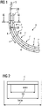
- a continuous casting plant has a mold 1 and a strand guide 2 .
- the strand guide 2 is the mold 1 downstream.
- Liquid metal 3 - for example steel or aluminum - is poured into the mold 1 .
- the liquid metal 3 solidifies on the contact surfaces of the mold 1 and is drawn off from the mold 1 in a strand conveying direction x by means of the strand guide 2 as a slab-shaped metal strand 4—usually with a core that is still liquid.
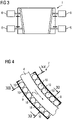
- the metal strand 4 has according to FIG 2 transverse to the strand conveying direction x has a strand width bS.
- the strand width bS lies between a minimum width bmin and a maximum width bmax.
- the minimum width bmin and the maximum width bmax are determined in particular by the construction of the mold 1.
- Narrow sides 5 of the mold 1 can be adjusted by means of adjusting devices 6 (usually hydraulic cylinder units).
- the range within which the narrow sides 5 can be adjusted by the adjusting devices 6 determines the minimum width bmin and the maximum width bmax.
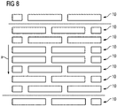
- the strand guide 2 has according to FIG 1 several segments 7 on.
- the segments 7 follow one another sequentially in the strand conveying direction x.
- the strand conveying direction x runs as shown in FIG FIG 1 usually initially vertical or nearly vertical.
- the strand conveying direction x changes in the casting curve as shown in FIG 1 usually their absolute direction in space gradually further and further in the horizontal direction.
- the segments 7 have according to the FIG 1 and 4 each have an inner segment part 8 and an outer segment part 9 .
- the outer segment part 9 is usually stationary within the continuous casting plant.
- the inner segment part 8 is generally movable relative to the outer segment part 9 .
- the positioning of the segment parts 8, 9 against each other can be done, for example, by means of hydraulic cylinder units, not shown.
- the inner segment part 8 is located on the side of the metal strand 4, which forms the upper side after the metal strand 4 has been bent into the horizontal.
- the outer segment part 9 is therefore that segment part which is located on the side of the metal strand 4 in the case of sheet systems, which forms the underside of the metal strand 4 after the metal strand 4 has been bent into the horizontal.
- the metal strand 4 is guided between the two segment parts 8 , 9 of the respective segment 7 .
- the segment parts 8, 9 also each have a plurality of rollers 10.
- the rollers 10 follow one another sequentially in the strand conveying direction x.
- the rollers 10 guide and support the cast metal strand 4.
- the segment parts 8, 9 each have seven rollers 10, for example. However, this number is purely exemplary. The number of rollers 10 per segment 8, 9 could also be greater than seven or less than seven. However, the number of rollers 10 per segment 8, 9 is usually a minimum of four and a maximum of 20.
- the rear construction of the segment parts for supporting the rollers shown is not shown in detail, but this can be found, for example, in the "SMART Segment & DynaGap SoftReduction" brochure. of Siemens VAI Metals Technologies from 2007.
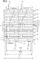
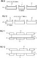
- 5 shows a plan view of the rollers 10, which is located on one of the two segment parts 8, 9 of FIG 4 support. 5 additionally shows the last roll 10 of the corresponding segment part 8, 9 of the immediately preceding segment 7 and the first roll 10 of the corresponding segment part 8, 9 of the immediately following segment 7.
- the boundaries of the fully shown segment part 8, 9 are in 5 indicated by horizontal dashed lines.
- the rollers 10 have a total extension G.
- the overall extent G is—as is generally customary—chosen in such a way that it exceeds the maximum width bmax to a sufficient extent—for example by approximately 50 mm to approximately 80 mm.
- the rollers 10 are each divided into a plurality of bales 11 viewed transversely to the strand conveying direction x.
- the gaps 12 have a respective gap width bL.
- the gap widths bL are usually in the range from about 60 mm to about 150 mm. In the area of the gaps 12 takes place - in addition to the outer roller bearings - an additional storage and support of the rollers 10.
- the bales 11 and the gaps 12 and also the gap widths bL are provided with reference numbers only for the last roll 10 of the corresponding segment part 8, 9 of the immediately preceding segment 7 and the first roll 10 of the corresponding segment part 8, 9 of the immediately following segment 7.
- the corresponding assignment is off 5 but also for the rollers 10 of the segment part 8, 9 shown in full.
- the set of rollers shown for a segment part 8, 9 has (at least) one symmetrical roller 10.
- This roller 10 is usually driven or can be driven. this is in 5 indicated by the fact that this roller 10 is assigned a drive 13 .
- the difference between a driven roller 10 and a drivable roller 10 is that a driven roller 10 is firmly connected to its associated drive 13, while a drivable roller 10 is detachably connected to its associated drive 13, in particular via a detachable coupling that is only indicated 13'.
- the gaps 12 of the respective roller 10 are arranged symmetrically to the casting center line 14 or segment center line 14 viewed transversely to the strand conveying direction x.
- the two terms "casting center line” and “segment center line” are used synonymously below.
- the casting center line 14 is that line seen transversely to the strand conveying direction x, with respect to which the overall extension G of the rollers 10 is evenly distributed.
- the division of the symmetrical roll 10 into its individual balls 11 is preferably chosen such that the outer balls 11 of the symmetrical roll 10 extend at least 30 mm - preferably at least 40 mm - over the minimum width bmin inwards onto the pouring center line 14. This ensures that the outer bales 11 of the symmetrical roll 10 also convey the metal strand 4, regardless of the actual strand width bS. This also applies when the metal strand 4 is conveyed slightly eccentrically or slightly askew in the strand guide 2 .
- the gaps 12 of the respective roller 10 are arranged asymmetrically to the casting center line 14, viewed transversely to the strand conveying direction x.
- These rollers 10, ie the asymmetrical rollers 10, are not driven as a rule.
- the barrels 11 of one roll 10 correspond to the barrels 11 of the other roll 10 in inverse order.
- the offset V of the gaps 12 relative to the gaps 12 of the immediately following roller 10 is at least 10 mm greater than the gap width bL.
- the offset V of the gaps 12 relative to the gaps 12 of the immediately following roller 10 is at least 10 mm greater than the gap width bL.
- the first roller 10 of the respective segment part 8, 9 and the penultimate roller 10 of the respective segment part 8, 9 are identically designed asymmetrical rollers 10.
- the second roller is generally also seen in the strand conveying direction x 10 of the respective segment part 8, 9 and the last roller 10 of the respective segment part 8, 9 are asymmetric rollers of the same design 10. This results in the property that, seen transversely to the strand conveying direction x, the gaps 12 of the first roll 10 of a respective segment part 8, 9, seen in strand conveying direction x, are larger than the gaps 12 of the last roll 10 of the same segment part 8, 9, seen in strand conveying direction x are offset than the respective gap width bL.
- segment parts 8, 9 directly following one another in the strand conveying direction x can be of the same design. Nevertheless, it is still guaranteed that, viewed transversely to the strand conveying direction x, the gaps 12 of the last roller 10 of a respective segment part 8, 9, viewed in the strand conveying direction x, compared to the gaps 12 of the first roller 10 of the immediately following segment part 8, 9, viewed in the strand conveying direction x, by more than the respective gap width bL are offset.
- the division of the rollers 10 into their individual barrels 11 is preferably selected in such a way that the outer barrels 11 of the non-driven rollers 10 widen inwards by at least 30 mm - preferably by at least 40 mm - beyond the minimum width bmin to extend the pouring centerline 14. This ensures in particular that, regardless of the actual strand width bS, the inner edges of the outer barrels 11 of the asymmetrical rollers 10 run on the metal strand 4 itself, but do not hit its outer edge exactly. This also applies when the metal strand 4 is conveyed slightly off-center or slightly crooked.
- rollers of the segment part 8, 9 correspond in each pair of immediately consecutive asymmetrical rollers 10, the barrels 11 of one roller 10 in pairs with the barrels 11 of the other roller 11 in inverse order, so seen once from the left and from the right. Furthermore, the in 5 shown segment part 8, 9 only a single symmetrical role 10 on. This configuration is the norm. If the segment part 8, 9 has several symmetrical rollers 10, these rollers 10 are preferably not located at the borders of the upstream and downstream segment part 8, 9. Furthermore, in this case there is preferably at least at least one between symmetrical rollers 10 an asymmetric roll 10, in particular an even number of asymmetric rolls 10.
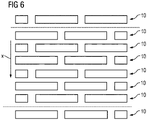
- the design of the roller set of the segment part 8, 9 according to 6 as such is not the subject of the present invention.
- the inside 6 shown segment part 8, 9 has in contrast to 5 no symmetrical role 10 on.
- the number of rolls 10 of the in 6 shown segment part 8, 9 is straight. In this case--that is, if there is no symmetrical roller 10 but the number of rollers 10 is even--as shown in FIG 6 Seen transversely to the strand conveying direction x, not a single roll 10 has the gaps 12 in the same places as in the immediately following roll 10. This also applies to the last roll 10 of the in 6 Completely illustrated segment part 8, 9.
- the above statements on the asymmetrical roles 10 of 5 are therefore 1:1 6 transferable.
- FIG 7 The design of the roller set of the segment part 8, 9 according to FIG 7 as such is also not the subject of the present invention.
- the gaps 12 in a roll 10 are in the same places as in the immediately following roll 10 . Exactly this can be avoided by the configuration according to the invention, in which there is at least one symmetrical roller 10 per segment part 8 , 9 .
- the gaps 12 are only in a single roll 10 in the same places as in the immediately following roll 10. In all other rolls 10 of the corresponding segment part 8, 9, the gaps 12 of the respective roll 10 are opposite the gaps 12 of the immediately following roll 10 offset by more than the respective gap width bL.
- the configuration of the segment part 8, 9 according to 8 as such is also not the subject of the present invention.
- the rollers of the segment parts 8, 9 shown correspond in pairs with the rollers 11 of the respective roller 10 with the rollers 11 of the immediately following roller 11.
- the bales 11 correspond to one another in the same order.
- the bales 11 correspond to one another in reverse order.
- the barrels 11 of the rolls 10 each have a barrel length 11, L1, 12, L2.
- l1 is here - see 9 - Denotes the minimum barrel length of a symmetrical roll 10, with L1 the maximum barrel length of a symmetrical roll 10.
- L1 the maximum barrel length of a symmetrical roll 10.
- L2 the maximum barrel length of an asymmetric roll 10.
- the barrels 11 of the rolls 10 have a respective roll diameter d1, d2.
- d1 is here - see 9 - denotes the diameter of the balls 11 of a symmetrical roll 10, with d2 - see 10 -
- the respective roll diameter d1, d2 is uniform for the barrel 11 of the respective roll 10.
- All symmetrical rollers 10 within the respective segment part 8, 9 preferably have the same roller diameter d1.
- all asymmetrical rollers 10 within the respective segment part 8, 9 preferably also have the same roller diameter d2.
- the roll diameter d1 of the symmetrical rolls 10 is preferably at least as - usually larger than - the roll diameter d2 of the asymmetrical rolls 10. Viewed in the strand conveying direction x, the roll diameters d1, d2 increase from segment 7 to segment 7 (or at least not smaller).
- the maximum barrel length L1, L2 is preferably between 3 times and 4.5 times the respective roll diameter d1, d2.
- the maximum barrel length L1 is preferably between 3 and 3.8 times the respective roll diameter d1.
- the maximum barrel length L1 can be between 3.2 times and 3.6 times the respective roller diameter d1, particularly preferably between 3.3 times and 3.5 times.
- the ratio of maximum barrel length L2 and diameter d2 can have a larger value.
- the maximum barrel length L2 is preferably between 3.5 times and 4.5 times the respective roll diameter d2.
- the maximum barrel length L2 can be between 3.7 times and 4.3 times the respective roller diameter d1, particularly preferably between 3.9 times and 4.1 times.
- the maximum bale length L1, L2 should not exceed an absolute value.
- the absolute value is usually in the range between 750 mm and 900 mm, in particular between 800 mm and 850 mm.
- the minimum bale length 11, 12 should not fall below an absolute value.
- the absolute value is usually between 200 mm and 350 mm, mostly around 250 mm to 300 mm.
- bales 11 of the respective roll 10 have a uniform bale length 11, L1, 12, L2 or only a single bale 11 has a different bale length 11, L1, from the other bales 11, 12, L2.
- the two outer bales 11 have a uniform (large) bale length L1, with inner bales 11--if they are also present--either having the same bale length L1 or a smaller bale length 11.
- an asymmetrical role 10 for example, as shown in the 5 to 8 one of the two outer balls 11 have a relatively small ball length 12, while all other balls 11 of the same roll 10 have a larger ball length L2.
- the reverse procedure one long bale 11 per roll 10, otherwise short bales 11 is also possible.
- the inner and outer segment parts 8, 9 of a respective segment 7 have an equal number of rollers 10. Furthermore, based on the cast metal strand 4, the rollers 10 of the inner and outer segment parts 8, 9 can be seen opposite one another.
- the inner segment part 8 is a mirror image of the outer segment part 9. For example, as in 11 for one roller 10 each of the inner and outer segment part 8, 9 of a segment 7, seen transversely to the strand conveying direction x, the gaps 12 between the barrels 11 of the rollers 10 of the inner segment part 8 are in the same places as the gaps 12 between the barrels 11 the respectively opposite roller 10 of the outer segment part 9 are located.
- rollers 10 of the inner and outer segment part 8, 9 which are designed as symmetrical rollers 10
- the opposite roller 10 of the outer or inner segment part 9, 8 is also designed as a symmetrical roller 10.
- the barrels 11 of the rollers 10 of the inner segment part 8 correspond to the barrels 11 of the respectively opposite roller 10 of the outer segment part 9 in the same order.
- the balls 11 of the rollers 10 of the inner segment part 8 correspond to the balls 11 of the respectively opposite roller 10 of the outer segment part 9 in reverse order.
- rollers 10 each have three barrels 11 according to the invention.
- the rollers 10 could also each have four and in some cases even five bales 11 .
Landscapes
- Engineering & Computer Science (AREA)
- Mechanical Engineering (AREA)
- Rollers For Roller Conveyors For Transfer (AREA)
Claims (14)
- Segment d'un guide-barre (2) d'une installation de coulée continue,- le segment (7) comprenant une partie de segment intérieure et une partie de segment extérieure (8, 9) entre lesquelles une barre métallique (4) est guidée pendant le fonctionnement,- les parties de segment (8, 9) comportant chacune plusieurs rouleaux (10) se succédant de manière séquentielle dans une direction de transport de barre (x) qui sont supportés par la partie de segment (8, 9) respective,- les rouleaux (10), vus perpendiculairement à la direction de transport de barre (x), étant divisés chacun en plusieurs corps (11)entre lesquels se trouve à chaque fois un intervalle (12) qui présente une largeur d'intervalle (bL) respective,dans lequel- en vue perpendiculaire à la direction de transport de barre (x), pour chaque partie de segment (8, 9), les intervalles (12) des rouleaux (10) sont décalés de plus de la largeur d'intervalle (bL) respective par rapport aux intervalles (12) du rouleau (10) venant à chaque fois immédiatement après,- dans le cas d'au moins un des rouleaux (10) de la partie de segment (8, 9) respective, les intervalles (12) du rouleau (10) respectif, vus perpendiculairement à la direction de transport de barre (x), sont agencés de manière symétrique par rapport à la ligne médiane de segment (14),- dans le cas des autres rouleaux (10) de la partie de segment (8, 9) respective, les intervalles (12) du rouleau (10) respectif, vus perpendiculairement à la direction de transport de barre (x), sont agencés de manière asymétrique par rapport à la ligne médiane de segment (14) et- pour chaque paire de rouleaux (10) immédiatement consécutifs de la partie de segment (8, 9) respective pour lesquels les intervalles (12) des deux rouleaux (10), vus perpendiculairement à la direction de transport de barre (x), sont agencés de manière asymétrique par rapport à la ligne médiane de segment (14), les corps (11)d'un rouleau (10) correspondent, en ordre inversé, aux corps (11)de l'autre rouleau (10),dans lequel, en outre,- en vue dans la direction de transport de barre (x), les intervalles (12), vus perpendiculairement à la direction de transport de barre (x), sont agencés de manière asymétrique par rapport à la ligne médiane de segment (14) aussi bien dans le cas du premier rouleau (10) que dans le cas du dernier rouleau (10) de la partie de segment (8, 9) respective,- les rouleaux (10) présentent à chaque fois trois, quatre ou cinq corps (11),- les corps (11)présentent une longueur de corps respective (l1, L1,l2, L2),- dans le cas des rouleaux (10) dont les intervalles (12), vus perpendiculairement à la direction de transport de barre (x), sont agencés de manière symétrique par rapport à la ligne médiane de segment (14), soit tous les corps (11)ont une longueur de corps uniforme (Ll), soit un seul corps (l1) uniquement présente une longueur de corps (l1, l2, L2) différente des autres corps (11)et- dans le cas des rouleaux (10) dont les intervalles (12), vus perpendiculairement à la direction de transport de barre (x), sont agencés de manière asymétrique par rapport à la ligne médiane de segment (14), un seul corps (11)uniquement présentant une longueur de corps (l1, l2, L2) différente des autres corps (11).
- Segment selon la revendication 1,
caractérisé en ce que, concernant chaque rouleau (10) dont les intervalles (12), vus perpendiculairement à la direction de transport de barre (x), sont agencés de manière symétrique par rapport à la ligne médiane de segment (14), les intervalles (12) du rouleau (10) le précédant immédiatement tout comme les intervalles (12) du rouleau (10) lui succédant immédiatement, vus perpendiculairement à la direction de transport de barre (x), sont agencés de manière asymétrique par rapport à la ligne médiane de segment (14). - Segment selon la revendication 1 ou 2,
caractérisé en ce que les corps (11)du premier rouleau (10), vu dans la direction de transport de barre (x), de la partie de segment (8, 9) respective correspondent, en ordre inverse, aux corps (11)du dernier rouleau (10), vu dans la direction de transport de barre (x), de la partie de segment (8, 9) respective. - Segment selon l'une des revendications précédentes,
caractérisé en ce qu'un entraînement (13) est à chaque fois associé, de manière fixe ou par le biais d'un accouplement (13'), aux rouleaux (10) de la partie de segment (8, 9) respective pour lesquels les intervalles (12) du rouleau (10) respectif, vus perpendiculairement à la direction de transport de barre (x), sont agencés de manière symétrique par rapport à la ligne médiane de segment (14). - Segment selon l'une des revendications précédentes,
caractérisé en ce que le décalage (V) des intervalles (12) par rapport aux intervalles (12) de chaque rouleau (10) immédiatement consécutif est supérieur d'au moins 10 mm à la largeur d'intervalle (bL). - Segment selon l'une des revendications précédentes,
caractérisé en ce que les corps (11)des rouleaux (10) ont une longueur de corps maximale (L1, L2) respective et un diamètre de rouleau (d1, d2) uniforme pour les corps (11) du rouleau (10) respectif, et en ce que la longueur de corps maximale (L1, L2) respective a une valeur comprise entre 3 fois et 4,5 fois le diamètre de rouleau (d1, d2) respectif. - Segment selon la revendication 6,
caractérisé en ce que la longueur de corps maximale (L1, L2) respective dans le cas des rouleaux (10) dont les intervalles (12), vus perpendiculairement à la direction de transport de barre (x), sont agencés de manière symétrique par rapport à la ligne médiane de segment (14) a une valeur comprise entre 3 fois et 3,8 fois le diamètre de rouleau (d1) respectif et, dans le cas des rouleaux (10) dont les intervalles (12), vus perpendiculairement à la direction de transport de barre (x), sont agencés de manière asymétrique par rapport à la ligne médiane de segment (14), une valeur comprise entre 3,5 fois et 4,5 fois le diamètre de rouleau (d2) respectif. - Segment selon l'une des revendications précédentes,
caractérisé en ce que les corps (11)ont une longueur de corps (l1, L1,l2, L2) respective, en ce que la longueur de corps (l1, L1,l2, L2) est de 250 mm au moins et de 900 mm au maximum. - Segment selon l'une des revendications précédentes,
caractérisé en ce que les rouleaux (10) dont les intervalles (12), vus perpendiculairement à la direction de transport de barre (x), sont agencés de manière asymétrique par rapport à la ligne médiane de segment (14) ont un diamètre de rouleau (d2) uniforme. - Segment selon la revendication 9,
caractérisé en ce que les rouleaux (10) de la partie de segment (8, 9) respective dont les intervalles (12), vus perpendiculairement à la direction de transport de barre (x), sont agencés de manière symétrique par rapport à la ligne médiane de segment (14) ont un diamètre de rouleau (d1) uniforme, et en ce que ce diamètre de rouleau (d1) est supérieur au diamètre de rouleau (d2) des rouleaux (10) dont les intervalles (12), vus perpendiculairement à la direction de transport de barre (x), sont agencés de manière asymétrique par rapport à la ligne médiane de segment (14). - Segment selon l'une des revendications précédentes,
caractérisé en ce que la partie de segment intérieure et la partie de segment extérieure (8, 9) ont un nombre de rouleaux (10) identique, en ce que les rouleaux (10) de la partie de segment intérieure et de la partie de segment extérieure (8, 9) sont situés en regard les uns des autres par rapport à la barre métallique (4), et en ce que, en vue perpendiculaire à la direction de transport de barre (x), les corps (11)des rouleaux (10) de la partie de segment intérieure (8) correspondent, dans le même ordre ou en ordre inverse, aux corps (11)du rouleau (10) de la partie de segment extérieure (9) lui faisant respectivement face. - Installation de coulée continue,- l'installation de coulée continue comprenant une lingotière (1) et un guide-barre (2) disposé après la lingotière (1),- la lingotière (1) permettant de couler une barre métallique (4) en forme de brame qui est tirée hors de la lingotière (1) dans une direction de transport de barre (x) grâce au guide-barre (2),- la barre métallique (4) ayant, en vue perpendiculaire à la direction de transport de barre (x), une largeur de barre (bS) qui est comprise entre une largeur minimale (bmin) et une largeur maximale (bmax),- la largeur minimale (bmin) et la largeur maximale (bmax) étant déterminées par la construction de la lingotière (1),- le guide-barre (2) comprenant plusieurs segments (7) selon l'une des revendications précédentes qui se succèdent de manière séquentielle dans la direction de transport de barre (x).
- Installation de coulée continue selon la revendication 12,
caractérisée en ce que, dans le cas des rouleaux (10) dont les intervalles (12), vus perpendiculairement à la direction de transport de barre (x), sont agencés de manière symétrique par rapport à la ligne médiane de segment (14), les corps extérieurs (11)s'étendent d'au moins 30 mm sur la largeur minimale (bmin) vers l'intérieur en direction de la ligne médiane de segment (14). - Installation de coulée continue selon la revendication 12 ou 13,
caractérisée en ce que, dans le cas également des rouleaux (10) dont les intervalles (12), vus perpendiculairement à la direction de transport de barre (x), sont agencés de manière asymétrique par rapport à la ligne médiane de segment (14), les corps extérieurs (11)s'étendent d'au moins 30 mm sur la largeur minimale (bmin) vers l'intérieur en direction de la ligne médiane de segment (14).
Applications Claiming Priority (1)
| Application Number | Priority Date | Filing Date | Title |
|---|---|---|---|
| ATA50425/2015A AT517252B1 (de) | 2015-05-27 | 2015-05-27 | Vermeidung von Wassergassen bei einer Strangführung |
Publications (3)
| Publication Number | Publication Date |
|---|---|
| EP3097995A1 EP3097995A1 (fr) | 2016-11-30 |
| EP3097995B1 EP3097995B1 (fr) | 2019-06-12 |
| EP3097995B2 true EP3097995B2 (fr) | 2022-11-02 |
Family
ID=55697116
Family Applications (1)
| Application Number | Title | Priority Date | Filing Date |
|---|---|---|---|
| EP16164086.7A Active EP3097995B2 (fr) | 2015-05-27 | 2016-04-06 | Segment de guidage de bramme d'une installation de coulee continue et installation de coulee continue |
Country Status (2)
| Country | Link |
|---|---|
| EP (1) | EP3097995B2 (fr) |
| AT (1) | AT517252B1 (fr) |
Families Citing this family (1)
| Publication number | Priority date | Publication date | Assignee | Title |
|---|---|---|---|---|
| EP4574306A1 (fr) * | 2023-12-18 | 2025-06-25 | Primetals Technologies Austria GmbH | Dispositif pour uniformiser le profil de température de la barre d'une installation de coulée continue |
Citations (4)
| Publication number | Priority date | Publication date | Assignee | Title |
|---|---|---|---|---|
| DE10039015C1 (de) † | 2000-08-10 | 2002-01-17 | Sms Demag Ag | Verfahren und Einrichtung zum Überwachen der Drehlager, insbesondere der Wälzlager, von in einem Stützrollengerüst von Metall-, insbesondere von Stahl-Stranggießvorrichtungen, gelagerten Stranggießstützrollen |
| JP2005014029A (ja) † | 2003-06-25 | 2005-01-20 | Jfe Steel Kk | 連続鋳造機 |
| EP2192313A1 (fr) † | 2007-09-21 | 2010-06-02 | JTEKT Corporation | Dispositif de paliers à roulement et dispositif à rouleaux pour installation de coulée continue |
| KR20140034482A (ko) † | 2012-09-12 | 2014-03-20 | 주식회사 포스코 | 연속주조장치의 세그먼트 롤 냉각수 테스트 장치 |
Family Cites Families (8)
| Publication number | Priority date | Publication date | Assignee | Title |
|---|---|---|---|---|
| DE1458158B2 (de) * | 1964-07-08 | 1970-05-06 | Mannesmann AG, 4000 Düsseldorf | Stützwalzengerüst für eine Stranggießanlage |
| JPS4951821U (fr) * | 1972-08-19 | 1974-05-08 | ||
| DE3013484A1 (de) * | 1980-04-08 | 1981-10-15 | Schloemann-Siemag AG, 4000 Düsseldorf | Koaxial benachbart gelagerte strangfuehrungsrollen in einer stahl-stranggiessanlage fuer brammen |
| DE102004054296B4 (de) | 2004-11-09 | 2021-11-11 | Sms Group Gmbh | Steuer- und / oder Regeleinrichtung für ein Stützrollengerüst einer Stranggießvorrichtung für Metalle, insbesondere für Stahlwerkstoffe |
| DE102005045838A1 (de) * | 2005-09-24 | 2007-03-29 | Sms Demag Ag | Kühlvorrichtung |
| JP2013094828A (ja) * | 2011-11-02 | 2013-05-20 | Jfe Steel Corp | 連続鋳造における二次冷却方法 |
| WO2013073593A1 (fr) * | 2011-11-15 | 2013-05-23 | 新日鐵住金株式会社 | Procédé de refroidissement secondaire et dispositif de refroidissement secondaire pour machine de coulée continue |
| JP5817689B2 (ja) * | 2012-09-10 | 2015-11-18 | 新日鐵住金株式会社 | 連続鋳造の二次冷却方法 |
-
2015
- 2015-05-27 AT ATA50425/2015A patent/AT517252B1/de active
-
2016
- 2016-04-06 EP EP16164086.7A patent/EP3097995B2/fr active Active
Patent Citations (4)
| Publication number | Priority date | Publication date | Assignee | Title |
|---|---|---|---|---|
| DE10039015C1 (de) † | 2000-08-10 | 2002-01-17 | Sms Demag Ag | Verfahren und Einrichtung zum Überwachen der Drehlager, insbesondere der Wälzlager, von in einem Stützrollengerüst von Metall-, insbesondere von Stahl-Stranggießvorrichtungen, gelagerten Stranggießstützrollen |
| JP2005014029A (ja) † | 2003-06-25 | 2005-01-20 | Jfe Steel Kk | 連続鋳造機 |
| EP2192313A1 (fr) † | 2007-09-21 | 2010-06-02 | JTEKT Corporation | Dispositif de paliers à roulement et dispositif à rouleaux pour installation de coulée continue |
| KR20140034482A (ko) † | 2012-09-12 | 2014-03-20 | 주식회사 포스코 | 연속주조장치의 세그먼트 롤 냉각수 테스트 장치 |
Non-Patent Citations (7)
| Title |
|---|
| 8th eccc Proceedings, 23-26 Juni 2014 † |
| ANONYMOUS: "Complete quality control, X-Cast LASr plant assistant", SMS GROUP - BROCHURE, May 2014 (2014-05-01) † |
| BRUCE D. HORN: "Continuous caster rolls: Design, function and performance", IRON AND STEEL ENGINEER, vol. 73, no. 7, 1 July 1996 (1996-07-01), pages 49 - 54 † |
| Englischsprachige Computerübersetzung der O6 † |
| Englischsprachige Computerübersetzung der O7 † |
| Rechnung/Lieferschein über die O2 † |
| Vortrag gehalten von Herrn Fischer auf der 8th eccc, 23-26 Juni 2014 † |
Also Published As
| Publication number | Publication date |
|---|---|
| AT517252A1 (de) | 2016-12-15 |
| EP3097995A1 (fr) | 2016-11-30 |
| AT517252B1 (de) | 2019-03-15 |
| EP3097995B1 (fr) | 2019-06-12 |
Similar Documents
| Publication | Publication Date | Title |
|---|---|---|
| DE2501956C2 (de) | Vorrichtung zum Stützen, Führen, Biegen bzw. Richten und Verformen eines breiten Gußstranges | |
| DE102011055066A1 (de) | Walze mit Kühlsystem | |
| WO2013000841A1 (fr) | Procédé de coulée continue d'une barre de coulée continue et installation de coulée continue | |
| EP3016762B1 (fr) | Installation de laminage de coulée continue et procédé de fabrication de produit laminé métallique | |
| EP1330321A1 (fr) | Procede et dispositif de coulee en continu et de formage subsequent d'une barre de coulee en acier, en particulier d'une barre de coulee sous forme de lingot ou preprofilee | |
| WO2009100813A1 (fr) | Dispositif de guidage de barre, notamment pour une installation de coulée continue de brame d'acier | |
| WO2009144001A1 (fr) | Guide-barre, en particulier pour installation de coulée continue de brames d'acier | |
| EP3097995B2 (fr) | Segment de guidage de bramme d'une installation de coulee continue et installation de coulee continue | |
| EP3256276B1 (fr) | Installation de coulage | |
| WO2012139968A1 (fr) | Procédé et installation de coulée continue verticale permettant de produire des brames épaisses à partir d'une masse de métal fondu | |
| DE2731748B2 (de) | Rollenführungsgerüst für eine Stahlstranggießanlage | |
| EP1313580B1 (fr) | Dispositif de coulee continue de metaux, notamment d'acier | |
| EP0960671A2 (fr) | Segment de guidage des barres pour installations de coulée de brames | |
| EP1385656B1 (fr) | Procede pour la coulee continue de blocs, de brames ou de brames minces | |
| DE102005059692A1 (de) | Verfahren zum Stranggießen dünner Metallbänder und Stranggießanlage | |
| DE4403046C1 (de) | Rolle für ein Strangführungsgerüst | |
| DE19637545B4 (de) | Vorrichtung zur Umleitung eines in einer Stranggießkokille gegossenen Dünnbrammenstranges aus der Vertikalen in eine horizontale Ausförderrichtung | |
| DE3029990C2 (de) | Stranggieß-Walzengerüst für Mehrstranggießanlagen zum Stranggießen von Metall, insbesondere von Stahl | |
| DE69513263T2 (de) | Vorrichtung zum Stranggiessen von Produkten mit einem Rundprofilabschnitt und Produkten mit einem Profilabschnitt mit ebener Fläche | |
| EP4489928B1 (fr) | Segment arqué d'un dispositif de guidage de barre | |
| DE3427708C2 (de) | Vorrichtung zum seitlichen Führen eines Stranges einer Knüppel-Stranggießanlage | |
| DE2503494A1 (de) | Strangfuehrungsgeruest in einer stranggiessanlage | |
| DE19537745A1 (de) | Stranggießkokille | |
| WO1997028916A1 (fr) | Gage a rouleaux d'appui pour installation de coulee en continu de metal, en particulier d'acier | |
| CH620613A5 (en) | Roller guide for a continuous steel-casting installation |
Legal Events
| Date | Code | Title | Description |
|---|---|---|---|
| PUAI | Public reference made under article 153(3) epc to a published international application that has entered the european phase |
Free format text: ORIGINAL CODE: 0009012 |
|
| AK | Designated contracting states |
Kind code of ref document: A1 Designated state(s): AL AT BE BG CH CY CZ DE DK EE ES FI FR GB GR HR HU IE IS IT LI LT LU LV MC MK MT NL NO PL PT RO RS SE SI SK SM TR |
|
| AX | Request for extension of the european patent |
Extension state: BA ME |
|
| STAA | Information on the status of an ep patent application or granted ep patent |
Free format text: STATUS: REQUEST FOR EXAMINATION WAS MADE |
|
| 17P | Request for examination filed |
Effective date: 20170530 |
|
| RBV | Designated contracting states (corrected) |
Designated state(s): AL AT BE BG CH CY CZ DE DK EE ES FI FR GB GR HR HU IE IS IT LI LT LU LV MC MK MT NL NO PL PT RO RS SE SI SK SM TR |
|
| GRAP | Despatch of communication of intention to grant a patent |
Free format text: ORIGINAL CODE: EPIDOSNIGR1 |
|
| STAA | Information on the status of an ep patent application or granted ep patent |
Free format text: STATUS: GRANT OF PATENT IS INTENDED |
|
| INTG | Intention to grant announced |
Effective date: 20190204 |
|
| GRAS | Grant fee paid |
Free format text: ORIGINAL CODE: EPIDOSNIGR3 |
|
| GRAA | (expected) grant |
Free format text: ORIGINAL CODE: 0009210 |
|
| STAA | Information on the status of an ep patent application or granted ep patent |
Free format text: STATUS: THE PATENT HAS BEEN GRANTED |
|
| AK | Designated contracting states |
Kind code of ref document: B1 Designated state(s): AL AT BE BG CH CY CZ DE DK EE ES FI FR GB GR HR HU IE IS IT LI LT LU LV MC MK MT NL NO PL PT RO RS SE SI SK SM TR |
|
| REG | Reference to a national code |
Ref country code: GB Ref legal event code: FG4D Free format text: NOT ENGLISH |
|
| REG | Reference to a national code |
Ref country code: CH Ref legal event code: EP |
|
| REG | Reference to a national code |
Ref country code: AT Ref legal event code: REF Ref document number: 1141935 Country of ref document: AT Kind code of ref document: T Effective date: 20190615 |
|
| REG | Reference to a national code |
Ref country code: DE Ref legal event code: R096 Ref document number: 502016004973 Country of ref document: DE |
|
| REG | Reference to a national code |
Ref country code: IE Ref legal event code: FG4D Free format text: LANGUAGE OF EP DOCUMENT: GERMAN |
|
| REG | Reference to a national code |
Ref country code: NL Ref legal event code: MP Effective date: 20190612 |
|
| REG | Reference to a national code |
Ref country code: LT Ref legal event code: MG4D |
|
| PG25 | Lapsed in a contracting state [announced via postgrant information from national office to epo] |
Ref country code: LT Free format text: LAPSE BECAUSE OF FAILURE TO SUBMIT A TRANSLATION OF THE DESCRIPTION OR TO PAY THE FEE WITHIN THE PRESCRIBED TIME-LIMIT Effective date: 20190612 Ref country code: HR Free format text: LAPSE BECAUSE OF FAILURE TO SUBMIT A TRANSLATION OF THE DESCRIPTION OR TO PAY THE FEE WITHIN THE PRESCRIBED TIME-LIMIT Effective date: 20190612 Ref country code: FI Free format text: LAPSE BECAUSE OF FAILURE TO SUBMIT A TRANSLATION OF THE DESCRIPTION OR TO PAY THE FEE WITHIN THE PRESCRIBED TIME-LIMIT Effective date: 20190612 Ref country code: AL Free format text: LAPSE BECAUSE OF FAILURE TO SUBMIT A TRANSLATION OF THE DESCRIPTION OR TO PAY THE FEE WITHIN THE PRESCRIBED TIME-LIMIT Effective date: 20190612 Ref country code: SE Free format text: LAPSE BECAUSE OF FAILURE TO SUBMIT A TRANSLATION OF THE DESCRIPTION OR TO PAY THE FEE WITHIN THE PRESCRIBED TIME-LIMIT Effective date: 20190612 Ref country code: NO Free format text: LAPSE BECAUSE OF FAILURE TO SUBMIT A TRANSLATION OF THE DESCRIPTION OR TO PAY THE FEE WITHIN THE PRESCRIBED TIME-LIMIT Effective date: 20190912 |
|
| PG25 | Lapsed in a contracting state [announced via postgrant information from national office to epo] |
Ref country code: RS Free format text: LAPSE BECAUSE OF FAILURE TO SUBMIT A TRANSLATION OF THE DESCRIPTION OR TO PAY THE FEE WITHIN THE PRESCRIBED TIME-LIMIT Effective date: 20190612 Ref country code: BG Free format text: LAPSE BECAUSE OF FAILURE TO SUBMIT A TRANSLATION OF THE DESCRIPTION OR TO PAY THE FEE WITHIN THE PRESCRIBED TIME-LIMIT Effective date: 20190912 Ref country code: LV Free format text: LAPSE BECAUSE OF FAILURE TO SUBMIT A TRANSLATION OF THE DESCRIPTION OR TO PAY THE FEE WITHIN THE PRESCRIBED TIME-LIMIT Effective date: 20190612 Ref country code: GR Free format text: LAPSE BECAUSE OF FAILURE TO SUBMIT A TRANSLATION OF THE DESCRIPTION OR TO PAY THE FEE WITHIN THE PRESCRIBED TIME-LIMIT Effective date: 20190913 |
|
| PG25 | Lapsed in a contracting state [announced via postgrant information from national office to epo] |
Ref country code: SK Free format text: LAPSE BECAUSE OF FAILURE TO SUBMIT A TRANSLATION OF THE DESCRIPTION OR TO PAY THE FEE WITHIN THE PRESCRIBED TIME-LIMIT Effective date: 20190612 Ref country code: EE Free format text: LAPSE BECAUSE OF FAILURE TO SUBMIT A TRANSLATION OF THE DESCRIPTION OR TO PAY THE FEE WITHIN THE PRESCRIBED TIME-LIMIT Effective date: 20190612 Ref country code: PT Free format text: LAPSE BECAUSE OF FAILURE TO SUBMIT A TRANSLATION OF THE DESCRIPTION OR TO PAY THE FEE WITHIN THE PRESCRIBED TIME-LIMIT Effective date: 20191014 Ref country code: NL Free format text: LAPSE BECAUSE OF FAILURE TO SUBMIT A TRANSLATION OF THE DESCRIPTION OR TO PAY THE FEE WITHIN THE PRESCRIBED TIME-LIMIT Effective date: 20190612 Ref country code: CZ Free format text: LAPSE BECAUSE OF FAILURE TO SUBMIT A TRANSLATION OF THE DESCRIPTION OR TO PAY THE FEE WITHIN THE PRESCRIBED TIME-LIMIT Effective date: 20190612 Ref country code: RO Free format text: LAPSE BECAUSE OF FAILURE TO SUBMIT A TRANSLATION OF THE DESCRIPTION OR TO PAY THE FEE WITHIN THE PRESCRIBED TIME-LIMIT Effective date: 20190612 |
|
| PG25 | Lapsed in a contracting state [announced via postgrant information from national office to epo] |
Ref country code: SM Free format text: LAPSE BECAUSE OF FAILURE TO SUBMIT A TRANSLATION OF THE DESCRIPTION OR TO PAY THE FEE WITHIN THE PRESCRIBED TIME-LIMIT Effective date: 20190612 Ref country code: IS Free format text: LAPSE BECAUSE OF FAILURE TO SUBMIT A TRANSLATION OF THE DESCRIPTION OR TO PAY THE FEE WITHIN THE PRESCRIBED TIME-LIMIT Effective date: 20191012 Ref country code: ES Free format text: LAPSE BECAUSE OF FAILURE TO SUBMIT A TRANSLATION OF THE DESCRIPTION OR TO PAY THE FEE WITHIN THE PRESCRIBED TIME-LIMIT Effective date: 20190612 |
|
| REG | Reference to a national code |
Ref country code: DE Ref legal event code: R026 Ref document number: 502016004973 Country of ref document: DE |
|
| PLBI | Opposition filed |
Free format text: ORIGINAL CODE: 0009260 |
|
| PLAX | Notice of opposition and request to file observation + time limit sent |
Free format text: ORIGINAL CODE: EPIDOSNOBS2 |
|
| PG25 | Lapsed in a contracting state [announced via postgrant information from national office to epo] |
Ref country code: TR Free format text: LAPSE BECAUSE OF FAILURE TO SUBMIT A TRANSLATION OF THE DESCRIPTION OR TO PAY THE FEE WITHIN THE PRESCRIBED TIME-LIMIT Effective date: 20190612 |
|
| 26 | Opposition filed |
Opponent name: SMS GROUP GMBH Effective date: 20200311 |
|
| PG25 | Lapsed in a contracting state [announced via postgrant information from national office to epo] |
Ref country code: PL Free format text: LAPSE BECAUSE OF FAILURE TO SUBMIT A TRANSLATION OF THE DESCRIPTION OR TO PAY THE FEE WITHIN THE PRESCRIBED TIME-LIMIT Effective date: 20190612 Ref country code: DK Free format text: LAPSE BECAUSE OF FAILURE TO SUBMIT A TRANSLATION OF THE DESCRIPTION OR TO PAY THE FEE WITHIN THE PRESCRIBED TIME-LIMIT Effective date: 20190612 |
|
| PG25 | Lapsed in a contracting state [announced via postgrant information from national office to epo] |
Ref country code: IS Free format text: LAPSE BECAUSE OF FAILURE TO SUBMIT A TRANSLATION OF THE DESCRIPTION OR TO PAY THE FEE WITHIN THE PRESCRIBED TIME-LIMIT Effective date: 20200224 Ref country code: SI Free format text: LAPSE BECAUSE OF FAILURE TO SUBMIT A TRANSLATION OF THE DESCRIPTION OR TO PAY THE FEE WITHIN THE PRESCRIBED TIME-LIMIT Effective date: 20190612 |
|
| PLBB | Reply of patent proprietor to notice(s) of opposition received |
Free format text: ORIGINAL CODE: EPIDOSNOBS3 |
|
| PG2D | Information on lapse in contracting state deleted |
Ref country code: IS |
|
| PG25 | Lapsed in a contracting state [announced via postgrant information from national office to epo] |
Ref country code: MC Free format text: LAPSE BECAUSE OF FAILURE TO SUBMIT A TRANSLATION OF THE DESCRIPTION OR TO PAY THE FEE WITHIN THE PRESCRIBED TIME-LIMIT Effective date: 20190612 |
|
| REG | Reference to a national code |
Ref country code: CH Ref legal event code: PL |
|
| PG25 | Lapsed in a contracting state [announced via postgrant information from national office to epo] |
Ref country code: FR Free format text: LAPSE BECAUSE OF NON-PAYMENT OF DUE FEES Effective date: 20200430 Ref country code: LU Free format text: LAPSE BECAUSE OF NON-PAYMENT OF DUE FEES Effective date: 20200406 Ref country code: LI Free format text: LAPSE BECAUSE OF NON-PAYMENT OF DUE FEES Effective date: 20200430 Ref country code: CH Free format text: LAPSE BECAUSE OF NON-PAYMENT OF DUE FEES Effective date: 20200430 |
|
| REG | Reference to a national code |
Ref country code: BE Ref legal event code: MM Effective date: 20200430 |
|
| PG25 | Lapsed in a contracting state [announced via postgrant information from national office to epo] |
Ref country code: BE Free format text: LAPSE BECAUSE OF NON-PAYMENT OF DUE FEES Effective date: 20200430 |
|
| GBPC | Gb: european patent ceased through non-payment of renewal fee |
Effective date: 20200406 |
|
| PG25 | Lapsed in a contracting state [announced via postgrant information from national office to epo] |
Ref country code: GB Free format text: LAPSE BECAUSE OF NON-PAYMENT OF DUE FEES Effective date: 20200406 Ref country code: IE Free format text: LAPSE BECAUSE OF NON-PAYMENT OF DUE FEES Effective date: 20200406 |
|
| PG25 | Lapsed in a contracting state [announced via postgrant information from national office to epo] |
Ref country code: MT Free format text: LAPSE BECAUSE OF FAILURE TO SUBMIT A TRANSLATION OF THE DESCRIPTION OR TO PAY THE FEE WITHIN THE PRESCRIBED TIME-LIMIT Effective date: 20190612 Ref country code: CY Free format text: LAPSE BECAUSE OF FAILURE TO SUBMIT A TRANSLATION OF THE DESCRIPTION OR TO PAY THE FEE WITHIN THE PRESCRIBED TIME-LIMIT Effective date: 20190612 |
|
| REG | Reference to a national code |
Ref country code: AT Ref legal event code: MM01 Ref document number: 1141935 Country of ref document: AT Kind code of ref document: T Effective date: 20210406 |
|
| PG25 | Lapsed in a contracting state [announced via postgrant information from national office to epo] |
Ref country code: MK Free format text: LAPSE BECAUSE OF FAILURE TO SUBMIT A TRANSLATION OF THE DESCRIPTION OR TO PAY THE FEE WITHIN THE PRESCRIBED TIME-LIMIT Effective date: 20190612 |
|
| PG25 | Lapsed in a contracting state [announced via postgrant information from national office to epo] |
Ref country code: AT Free format text: LAPSE BECAUSE OF NON-PAYMENT OF DUE FEES Effective date: 20210406 |
|
| PUAH | Patent maintained in amended form |
Free format text: ORIGINAL CODE: 0009272 |
|
| STAA | Information on the status of an ep patent application or granted ep patent |
Free format text: STATUS: PATENT MAINTAINED AS AMENDED |
|
| 27A | Patent maintained in amended form |
Effective date: 20221102 |
|
| AK | Designated contracting states |
Kind code of ref document: B2 Designated state(s): AL AT BE BG CH CY CZ DE DK EE ES FI FR GB GR HR HU IE IS IT LI LT LU LV MC MK MT NL NO PL PT RO RS SE SI SK SM TR |
|
| REG | Reference to a national code |
Ref country code: DE Ref legal event code: R102 Ref document number: 502016004973 Country of ref document: DE |
|
| PGFP | Annual fee paid to national office [announced via postgrant information from national office to epo] |
Ref country code: DE Payment date: 20250422 Year of fee payment: 10 |
|
| PGFP | Annual fee paid to national office [announced via postgrant information from national office to epo] |
Ref country code: IT Payment date: 20250424 Year of fee payment: 10 |
|
| REG | Reference to a national code |
Ref country code: DE Ref legal event code: R082 Ref document number: 502016004973 Country of ref document: DE Representative=s name: LINDNER BLAUMEIER, PATENT- UND RECHTSANWAELTE,, DE |