EP3098016B1 - Verfahren und system zur lasermarkierung eines substrats unter verwendung von synchronisierten laserstrahlen - Google Patents
Verfahren und system zur lasermarkierung eines substrats unter verwendung von synchronisierten laserstrahlen Download PDFInfo
- Publication number
- EP3098016B1 EP3098016B1 EP15382277.0A EP15382277A EP3098016B1 EP 3098016 B1 EP3098016 B1 EP 3098016B1 EP 15382277 A EP15382277 A EP 15382277A EP 3098016 B1 EP3098016 B1 EP 3098016B1
- Authority
- EP
- European Patent Office
- Prior art keywords
- energizing
- marking
- radiation
- substrate
- laser
- Prior art date
- Legal status (The legal status is an assumption and is not a legal conclusion. Google has not performed a legal analysis and makes no representation as to the accuracy of the status listed.)
- Active
Links
Images


Classifications
-
- B—PERFORMING OPERATIONS; TRANSPORTING
- B23—MACHINE TOOLS; METAL-WORKING NOT OTHERWISE PROVIDED FOR
- B23K—SOLDERING OR UNSOLDERING; WELDING; CLADDING OR PLATING BY SOLDERING OR WELDING; CUTTING BY APPLYING HEAT LOCALLY, e.g. FLAME CUTTING; WORKING BY LASER BEAM
- B23K26/00—Working by laser beam, e.g. welding, cutting or boring
- B23K26/352—Working by laser beam, e.g. welding, cutting or boring for surface treatment
-
- B—PERFORMING OPERATIONS; TRANSPORTING
- B23—MACHINE TOOLS; METAL-WORKING NOT OTHERWISE PROVIDED FOR
- B23K—SOLDERING OR UNSOLDERING; WELDING; CLADDING OR PLATING BY SOLDERING OR WELDING; CUTTING BY APPLYING HEAT LOCALLY, e.g. FLAME CUTTING; WORKING BY LASER BEAM
- B23K26/00—Working by laser beam, e.g. welding, cutting or boring
- B23K26/02—Positioning or observing the workpiece, e.g. with respect to the point of impact; Aligning, aiming or focusing the laser beam
- B23K26/06—Shaping the laser beam, e.g. by masks or multi-focusing
- B23K26/0604—Shaping the laser beam, e.g. by masks or multi-focusing by a combination of beams
- B23K26/0608—Shaping the laser beam, e.g. by masks or multi-focusing by a combination of beams in the same heat affected zone [HAZ]
-
- B—PERFORMING OPERATIONS; TRANSPORTING
- B23—MACHINE TOOLS; METAL-WORKING NOT OTHERWISE PROVIDED FOR
- B23K—SOLDERING OR UNSOLDERING; WELDING; CLADDING OR PLATING BY SOLDERING OR WELDING; CUTTING BY APPLYING HEAT LOCALLY, e.g. FLAME CUTTING; WORKING BY LASER BEAM
- B23K26/00—Working by laser beam, e.g. welding, cutting or boring
- B23K26/02—Positioning or observing the workpiece, e.g. with respect to the point of impact; Aligning, aiming or focusing the laser beam
- B23K26/06—Shaping the laser beam, e.g. by masks or multi-focusing
- B23K26/0604—Shaping the laser beam, e.g. by masks or multi-focusing by a combination of beams
- B23K26/0613—Shaping the laser beam, e.g. by masks or multi-focusing by a combination of beams having a common axis
-
- B—PERFORMING OPERATIONS; TRANSPORTING
- B23—MACHINE TOOLS; METAL-WORKING NOT OTHERWISE PROVIDED FOR
- B23K—SOLDERING OR UNSOLDERING; WELDING; CLADDING OR PLATING BY SOLDERING OR WELDING; CUTTING BY APPLYING HEAT LOCALLY, e.g. FLAME CUTTING; WORKING BY LASER BEAM
- B23K26/00—Working by laser beam, e.g. welding, cutting or boring
- B23K26/08—Devices involving relative movement between laser beam and workpiece
- B23K26/082—Scanning systems, i.e. devices involving movement of the laser beam relative to the laser head
-
- B—PERFORMING OPERATIONS; TRANSPORTING
- B23—MACHINE TOOLS; METAL-WORKING NOT OTHERWISE PROVIDED FOR
- B23K—SOLDERING OR UNSOLDERING; WELDING; CLADDING OR PLATING BY SOLDERING OR WELDING; CUTTING BY APPLYING HEAT LOCALLY, e.g. FLAME CUTTING; WORKING BY LASER BEAM
- B23K26/00—Working by laser beam, e.g. welding, cutting or boring
- B23K26/36—Removing material
- B23K26/361—Removing material for deburring or mechanical trimming
-
- B—PERFORMING OPERATIONS; TRANSPORTING
- B41—PRINTING; LINING MACHINES; TYPEWRITERS; STAMPS
- B41J—TYPEWRITERS; SELECTIVE PRINTING MECHANISMS, i.e. MECHANISMS PRINTING OTHERWISE THAN FROM A FORME; CORRECTION OF TYPOGRAPHICAL ERRORS
- B41J2/00—Typewriters or selective printing mechanisms characterised by the printing or marking process for which they are designed
- B41J2/435—Typewriters or selective printing mechanisms characterised by the printing or marking process for which they are designed characterised by selective application of radiation to a printing material or impression-transfer material
- B41J2/475—Typewriters or selective printing mechanisms characterised by the printing or marking process for which they are designed characterised by selective application of radiation to a printing material or impression-transfer material for heating selectively by radiation or ultrasonic waves
-
- B—PERFORMING OPERATIONS; TRANSPORTING
- B41—PRINTING; LINING MACHINES; TYPEWRITERS; STAMPS
- B41M—PRINTING, DUPLICATING, MARKING, OR COPYING PROCESSES; COLOUR PRINTING
- B41M5/00—Duplicating or marking methods; Sheet materials for use therein
- B41M5/26—Thermography ; Marking by high energetic means, e.g. laser otherwise than by burning, and characterised by the material used
Definitions
- the present invention generally relates to a method of marking a substrate and to a system for marking a substrate according to the preamble of claims 1 and 7 respectively (see, for example, US2008/123509 A1 ).
- the present invention is particularly applied to the laser marking of fabrics.
- JP2004017104A discloses a laser marker including pre-heating means for pre-heating the area of the substrate to be marked and a semiconductor laser for marking the pre-heated area.
- pre-heating means for pre-heating the area of the substrate to be marked
- semiconductor laser for marking the pre-heated area.
- the use of a semiconductor laser of relatively low output is possible for marking because of the mentioned pre-heating of the area of the substrate to be marked.
- the pre-heating means include a high power lamp or, for an alternative embodiment, the same marking laser diode, in which case said laser diode is used collimated in a pre-heating step and, after the pre-heating step, it is used condensed into a focused marking spot for the marking step.
- EP1684986B1 discloses a laser marking system which uses a low energy laser array for marking a substrate, together with a heater to heat the substrate prior to radiating the substrate so that the energy required to be provided by the array of lasers for marking the substrate is minimized.
- the heater for performing the pre-heating of the substrate is a light emitter, such as a laser.
- the heater is stationary, i.e., the pre-heating radiation is not moved.
- the energizing irradiation is applied to the complete laser sensitive area of the substrate which includes the portion to be laser marked, and, although there are disclosed embodiments for which the substrate is running and the marking is made on the fly and other embodiments for which the substrate to be marked may instead be stationary, moved in slow speed or moved by indexing a step at a time, none of said embodiments neither discloses nor suggests the moving of the energizing irradiation through various sensitive areas of the substrate.
- the present invention provides a method of laser marking a substrate as defined in claim 1. Contrary to the method disclosed in WO2011035909A1 , in the method of the first aspect of the present invention, the irradiation of said step a) and the irradiation of said step b) are performed by directing both the energizing radiation and the marking laser beam towards various areas of said substrate and portions thereof, respectively, in a synchronized manner.
- At least said areas of the substrate are heat-sensitive, the energizing radiation source of step a) being a heat energy source selected to heat said areas.
- the method of the present invention comprises performing said synchronized radiation movements such that at least some of said various areas of the substrate are partially overlapped and at least some of said portions thereof are included in the overlapped regions resulting from said areas overlapping.
- the marking radiation is applied to a region which is being irradiated simultaneously with the energizing radiation but which has also been pre-energized by a previous irradiation with the energizing radiation, as said region includes at least one section of each of two consecutive of the mentioned areas of the substrate: a first one already energized and another being currently energized.
- the energy density for both, the energizing radiation and the marking laser beam must be well calculated taking into account whether the laser marks will be made in overlapping energized regions or not.
- the energizing radiation source is an energizing laser source (such as a CO 2 laser source) configured and arranged to generate an energizing laser beam impinging on said areas of the substrate with a spot diameter approximately one order of magnitude larger than the spot diameter of the marking laser beam impinging on said portions of said areas.
- an energizing laser source such as a CO 2 laser source
- said spot diameter of the impinged zone of the energizing laser beam is in the order of several millimetres, while the spot diameter of the impinged zone of the marking laser beam is in the order of tens to hundreds of micrometres.
- Such a spot diameter of the energizing laser beam when impinging on the substrate areas is achieved, for a preferred embodiment, by using a collimated energizing laser beam having a beam diameter coincident with said spot diameter, although for another less preferred embodiment the energizing laser beam is focused but to a focal plane which is in front or behind the substrate plane.
- the power density of the energizing laser beam when impinging on the substrate will be much lower than the power density of the marking laser beam when impinging on the substrate.
- energizing radiation sources are also covered by the present invention, according to less preferred embodiments, such as an infrared radiation source or a hot air radiation source.
- the marking laser source operates according to a pulsed laser mode, although its operation according to a continuous wave mode is also embraced by the present invention but less preferred.
- the substrate is a fabric, such as denim.
- said radiation redirecting means comprises a joint light reflecting and/or light deflecting and/or light diffracting arrangement for redirecting both the energizing and the marking laser beams simultaneously towards said various areas of the substrate and portions thereof.
- the system of the second aspect of the invention comprises an optical combiner configured and arranged for combining the energizing and the marking laser beams such that the resulting combined laser beams enter said common light reflecting and/or light deflecting arrangement collinearly following a common optical path.
- the optical axes of the energizing and the marking laser beams are inclined with respect to each other at the entry of said common light reflecting and/or light deflecting arrangement, and combined there within by a reflecting, deflecting or diffracting element such that they exit therefrom collinearly following a common path.
- Said common light reflecting and/or light deflecting arrangement is, for a preferred embodiment, a galvanometer scanner, and, for another embodiment it comprises a polygon scanner.
- the radiation redirecting means comprises two physically independent, but operationally synchronized, light reflecting and/or light deflecting arrangements (such as galvanometer scanners or polygon scanners), each for respectively redirecting one of said energizing and marking laser beams towards said various areas of the substrate and portions thereof.
- two physically independent, but operationally synchronized, light reflecting and/or light deflecting arrangements such as galvanometer scanners or polygon scanners, each for respectively redirecting one of said energizing and marking laser beams towards said various areas of the substrate and portions thereof.
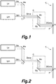
- Figures 1-3 and 7 show different optical arrangements representative of different embodiments of the present invention, all of them including the above described energizing laser source Le generating an energizing laser beam Be in an area A, and the marking laser source Lm generating a marking laser beam Bm in an area or portion P.
- the power density of the marking laser beam Bm when impinging on the substrate S is of the order of hundreds of MW/m 2 (such as of 600 MW/m 2 ), which causes the volatilization of surface particles of the material, which when, for a preferred embodiment, the material of the substrate is denim (such as jeans), i.e., a dyed fabric, the fabric dye is eliminated (at least partially) which causes a worn look effect, while the power density of the energizing laser beam Be being when impinging on the substrate S is only of the order of a few MW/m 2 (such us 6 MW/m 2 ) which does not cause a volatilization effect but a thermal transfer process which ultimately brings about an increase in the surface temperature.
- a diameter ratio A/P of the order of 10 results in the power density ratio of the order of 100.
- both the energizing (generally heating) of the regions to be marked (and surrounding regions) and the marking thereof are performed at a time, i.e., the marking laser energy is applied while the energizing laser energy is also being applied, even if deciding to mark different and distant regions of the substrate S following fast and intricate movements, as the movements of the marking laser beam Bm are synchronously followed by the movements of the energizing laser beam Be.
- Figure 4 shows how the energy is distributed on the substrate S, particularly in the laser impinging regions, by particularly showing two energized pulsed laser spots performed with beam Be in two corresponding overlapped areas A of the substrate S and two pulsed marking laser spots performed with beam Bm in two centred portions P of said areas A.
- the marks are only caused at portions P, as the energy threshold required for marking is only achieved in said portions P.
- the present inventors have performed several experimental tests of laser marking on different kind of denims (pure indigo, sulphide indigo, viscose, etc.) with different power levels of the energizing laser beam Be, with one and even several consecutive steps for applying the laser marking beam Bm on the same spots, with and without pre-heating the substrate S, with different pixel times (shorter than the pixel times used when only Bm is applied), etc., and the obtained results have shown the suitability and accuracy of the present invention as compared with the proposals of the prior art, particularly due to the fact that the regions to be marked are submitted to the laser energy from both laser beams Be and Bm simultaneously, and thus said regions have not begun to de-energize/cool when Bm is applied thereto.
- the optical arrangement there shown includes a common galvanometer scanner G, including moving mirrors Mx and My, for moving together both beams Be and Bm, once the beams have been combined into combined beams Bme (two overlapped beams having different spatial features, in particular their diameter and divergence), by means of optical combiner C1, which is a special mirror having an aperture facing beam Bm which allows said beam Bm to pass therethrough towards mirror Mx and a reflecting surface facing mirror Me to reflect beam Be also towards mirror Mx.
- optical combiner C1 which is a special mirror having an aperture facing beam Bm which allows said beam Bm to pass therethrough towards mirror Mx and a reflecting surface facing mirror Me to reflect beam Be also towards mirror Mx.
- the combined beams have been indicated in Figure 1 as Bme when entering the galvanometer scanner G and as BSme when exiting therefrom, the latter combined beams impinging on substrate S, particularly component Be on area A and component Bm on portion P.
- the arrangement of Figure 2 only differs from the one of Figure 1 in that it includes a different beam combiner C2, particularly a conventional beam combiner which allows the passage of beam Bm therethrough while it reflects beam Be, redirecting both beams, combined in the form of Bme, towards the galvanometer scanner G.
- Beam combiner C2 could be a polarizing beam splitter and beams Be and Bm could have mutually orthogonal polarizations in order to reduce energy losses and to maximize the efficiency of the combining of the beams.
- the arrangement of Figure 3 operates without the mentioned beam combiner, by means of providing different optical paths for the beams Be and Bm, in this case by tilting energizing laser source Le such that beam Be follows an inclined path with respect to the path followed by Bm towards mirror Mx of the common galvanometer G.
- beams Be and Bm are combined within galvanometer G after been reflected by mirror Mx that could be a polarizing beam splitter, diffraction grating (Be and Bm may have different wavelengths), etc., such that they exit therefrom collinearly following a common path in the form of BSme.
- the optical arrangement depicted in Figure 7 does not include a common galvanometer but two galvanometers G1 and G2, which are physically independent but operationally synchronized, one (G1) for redirecting beam Be and the other one (G2) for redirecting beam Bm.
- FIGS 5a and 5b Those areas A1...An and portions thereof P1...Pn are depicted in Figures 5a and 5b , for an embodiment in which a marking line has been produced on substrate S, said marking line being formed by a row of n marking spots performed in n respective portions P1...Pn of n areas A1...An on which a row of n energized laser spots is produced, in this case with a much larger spot diameter than the marking spot diameter.
- the portions P1 ...Pn can be centred with regard to areas A1...An, or not.
- the consecutive areas A1...An are partially overlapped (regularly as in the Figure or irregularly), and the portions P1...Pn can be included in the overlapped regions resulting from the overlapping of said areas.
- the marking laser beam Bm is applied not only within an area being energised at the same time with laser beam Be but also within an area which had already been energized at a previous application of laser beam Be, i.e., to a pre-energized area.
- the marking laser beam Bm is applied to P2 at the same time that Be is applied to A2 but also once Be had already been applied to A1 at the time when Bm was applied to P1.
- Figure 6 shows a block diagram of the system of the present invention, for an embodiment valid for implementing the method of the first aspect of the invention according to the embodiments of Figures 1 and 2 , i.e., the ones using a beam combiner C and a joint galvanometer G, which apart from the optical arrangement of the system also shows, schematically, the control arrangement of the system, i.e., the control means CU controlling the operation of both laser sources Le and Lm and the operation of the common galvanometer G.
- the control arrangement of the system i.e., the control means CU controlling the operation of both laser sources Le and Lm and the operation of the common galvanometer G.
- control lines have been depicted as thin lines and optical lines as thicker lines.
- each of laser sources Le and Lm is respectively excited by a radio frequency source RF1 and RF2, which is supplied by a corresponding DC source DC1 and DC2.
- RF1 and RF2 radio frequency source
- DC1 and DC2 DC sources
- Other kinds of excitation sources for the laser sources Le and Lm are also possible for other embodiments (not shown) of the system of the second aspect of the invention (such as optical, electrical, gas-dynamical, chemical, or electron-beam pumping sources).
- the DC supplied to the RF sources RF1 and RF2, and thus the excitation energy delivered to laser sources Le and Lm, is controlled by control unit CU, in order to control the generation of the laser beams Be and Bm, respectively.
- combiner C combines both beams Be and Bm into overlapping beams Bme which enter joint galvanometer scanner G redirecting the entry beams Bme as output beams BSme towards the various areas A1...An of substrate S within which portions P1...Pn to be marked are situated.
- Galvanometer scanner G is also controlled by control unit CU to modulate/scan the beams BSme (containing both beams Be and Bm) to produce the desired marking lines, according to marking patterns delivered from control computer CC and designed and/or inputted thereto by an operator.
- the heating source could be of any type such as bombardment with electrons, protons or other particles, radio waves, etc., or the laser aimed to heat the various areas of the substrate could trigger an exothermic chemical reaction to heat the material to be marked instead of heating the substrate directly.
Landscapes
- Physics & Mathematics (AREA)
- Optics & Photonics (AREA)
- Engineering & Computer Science (AREA)
- Plasma & Fusion (AREA)
- Mechanical Engineering (AREA)
- Health & Medical Sciences (AREA)
- General Health & Medical Sciences (AREA)
- Toxicology (AREA)
- Laser Beam Processing (AREA)
- Dot-Matrix Printers And Others (AREA)
Claims (14)
- Verfahren zur Lasermarkierung eines Substrats, umfassend:a) Bestrahlen eines Bereichs (A) des Substrats (S) mit energiezuführender Strahlung, die von einer energiezuführenden Strahlungsquelle (Le) erzeugt wird, damit der bestrahlte Bereich (A) 5 weniger Laserenergie benötigt, um lasermarkiert zu werden; undb) Bestrahlen eines Abschnitts (P) des Bereichs (A) mit Markierungsstrahlung von einem Markierungslaserstrahl (Bm), der von einer Markierungslaserquelle (Lm) erzeugt wird, um den Abschnitt (P) des Bereichs (A) zu lasermarkieren;wobei die Bestrahlungen von der energiezuführenden Strahlungsquelle (Le) und von der Markierungslaserquelle (Lm) einander zumindest teilweise räumlich und zeitlich überschneiden;
wobei die Bestrahlung in Schritt a) und die Bestrahlung in Schritt b) dadurch ausgeführt werden, indem sowohl die energiezuführende Strahlung (Be) als auch der Markierungslaserstrahl (Bm) auf synchronisierte Art und Weise jeweils auf verschiedene Bereiche (A1... An) des Substrats (S) und Abschnitte (P1... Pn) davon bewegt werden;
dadurch gekennzeichnet, dass die synchronisierten Bewegungen der Markierungsstrahlung und der energiezuführenden Strahlung so ausgeführt werden, dass zumindest einige der Bereiche (A1... An) des Substrats (S) sich teilweise überschneiden und einer oder mehrere der Abschnitte (P1... Pn) davon in den sich überschneidenden Regionen enthalten sind, die sich aus dem Überschneiden der verschiedenen Bereiche (A1... An) ergeben, sowie dadurch, dass
die Markierungsstrahlung auf dem Abschnitt (P) des Bereichs (A1... An) aufgebracht wird, der gleichzeitig mit der energiezuführenden Strahlung bestrahlt wird, dem jedoch auch durch eine vorangehende Bestrahlung mit der energiezuführenden Strahlung Energie zugeführt wurde, wobei der Abschnitt (P) mindestens einen Teil jedes der zwei aufeinanderfolgenden Bereiche (A1... An) des Substrats (S) enthält, wobei einem davon bereits Energie zugeführt wurde und einem anderen aktuell Energie zugeführt wird. - Verfahren nach Anspruch 1, wobei das Substrat (S) ein Stoff ist.
- Verfahren nach einem der Ansprüche 1 oder 2, wobei mindestens die Bereiche (A1... An) des Substrats (S) folgendes sind:- wärmeempfindlich, wobei die energiezuführende Strahlungsquelle (Le) aus Schritt a) eine Wärmeenergiequelle ist, die zur Erwärmung der Bereiche (A1... An) ausgewählt ist, und/oder- wellenlängenempfindlich einer bestimmten Wellenlänge gegenüber, wobei die von der energiezuführenden Strahlungsquelle (Le) aus Schritt a) erzeugte Strahlung die Form einer Strahlungswelle hat, die diese spezifische Wellenlänge aufweist.
- Verfahren nach Anspruch 3, wobei die energiezuführende Strahlungsquelle (Le) eine energiezuführende Laserquelle ist, die dazu konfiguriert und angeordnet ist, einen energiezuführenden Laserstrahl (Be) zu erzeugen, der auf die Bereiche (A1... An) des Substrats (S) mit einem Punktdurchmesser auftrifft, der um einige Male größer ist als der Punktdurchmesser des Markierungslaserstrahls (Bm), der auf die Abschnitte (P1... Pn) der Bereiche (A1... An) auftrifft.
- Verfahren nach Anspruch 4, wobei die energiezuführende Laserquelle (L2) dazu konfiguriert und angeordnet ist, einen energiezuführenden Laserstrahl (Be) zu erzeugen, der auf die Bereiche (A1... An) des Substrats (S) mit einem Punktdurchmesser auftrifft, der circa eine Größenordnung größer ist als der Punktdurchmesser des Markierungslaserstrahls (Bm), der auf die Abschnitte (P1... Pn) der Bereiche (A1... An) auftrifft.
- Verfahren nach einem der Ansprüche 4 oder 5, wobei zumindest die Markierungslaserquelle (Lm) in einem gepulsten Lasermodus betrieben wird.
- System zur Lasermarkierung eines Substrats, umfassend:- Erste Bestrahlungsmittel, eine energiezuführende Strahlungsquelle (Le) umfassend, die dazu konfiguriert und angeordnet ist, einen Bereich (A) des Substrats (S) mit energiezuführender Strahlung zu bestrahlen, die von der energiezuführenden Strahlungsquelle (Le) erzeugt wird, damit der bestrahlte Bereich (A) weniger Laserenergie benötigt, um lasermarkiert zu werden;- Zweite Bestrahlungsmittel, eine Markierungslaserquelle (Lm) umfassend, die dazu konfiguriert und angeordnet ist, einen Abschnitt (P) des Bereichs (A) mit Markierungsstrahlung von einem Markierungslaserstrahl (Bm) zu bestrahlen, der von der Markierungslaserquelle (Lm) erzeugt wird; und- Steuerungsmittel (CU), dazu konfiguriert und angeordnet, den Betrieb des ersten und zweiten Bestrahlungsmittels zu steuern, damit sie so wirken, dass die Bestrahlungen von der energiezuführenden Strahlungsquelle (Le) und von der Markierungslaserquelle (Lm) einander zumindest teilweise räumlich und zeitlich überschneiden;- Die ersten und zweiten Bestrahlungsmittel umfassen Strahlungsumlenkungsmittel, dadurch gekennzeichnet, dass:- Das Steuerungsmittel (CU) dazu konfiguriert und angeordnet ist, den Betrieb der Strahlungsumlenkungsmittel zu steuern, um sowohl die energiezuführende Strahlung als auch den Markierungslaserstrahl (Bm) so zu bewegen, dass sie auf synchronisierte Art und Weise jeweils auf verschiedene Bereiche (A1... An) des Substrats (S) und Abschnitte (P1... Pn) davon bewegt werden;Wobei die synchronisierten Strahlungsbewegungen so ausgeführt werden, dass zumindest einige der Bereiche (A1... An) des Substrats (S) sich teilweise überschneiden und einer oder mehrere der Abschnitte (P1... Pn) davon in den sich überschneidenden Regionen enthalten sind, die sich aus dem Überschneiden der verschiedenen Bereiche (A1... An) ergeben,
wobei die Markierungsstrahlung auf dem Abschnitt des Bereichs (A1... An) aufgebracht wird, der gleichzeitig mit der energiezuführenden Strahlung bestrahlt wird, dem jedoch auch durch eine vorangehende Bestrahlung mit energiezuführender Strahlung Energie zugeführt wurde, wobei der Abschnitt (P) mindestens einen Teil jedes der zwei aufeinanderfolgenden Bereiche (A1... An) des Substrats (S) enthält, wobei einem davon bereits Energie zugeführt wurde und einem anderen aktuell Energie zugeführt wird. - System nach Anspruch 7, wobei das Substrat (S) ein Stoff ist.
- System nach Anspruch 7 oder 8, wobei die energiezuführende Strahlungsquelle (Le) eine energiezuführende Laserquelle ist, die dazu konfiguriert und angeordnet ist, einen energiezuführenden Laserstrahl (Be) zu erzeugen, der auf die Bereiche (A1... An) des Substrats (S) mit einem Punktdurchmesser auftrifft, der circa eine Größenordnung größer ist als der Punktdurchmesser des Markierungslaserstrahls (Bm), der auf die Abschnitte (P1... Pn) der Bereiche (A1... An) auftrifft.
- System nach Anspruch 7, wobei das Strahlungsumlenkungsmittel eine gemeinsame lichtreflektierende und/oder lichtablenkende und/oder lichtbrechende Anordnung (G) umfasst, um sowohl den energiezuführenden als auch den Markierungslaserstrahl (Be, Bm) gleichzeitig auf die verschiedenen Bereiche (A1... An) des Substrats (S) und Abschnitte (P1... Pn) davon umzulenken.
- System nach Anspruch 10, einen optischen Kombinierer (C, C1, C2) umfassend, der dazu konfiguriert und angeordnet ist, den energiezuführenden und den Markierungslaserstrahl (Be, Bm) so zu kombinieren, dass die resultierenden kombinierten Laserstrahlen (Bme) in die gemeinsame lichtreflektierende und/oder lichtablenkende Anordnung (G) eintreten, die einem gemeinsamen optischen Pfad folgend miteinander ausgerichtet sind.
- System nach Anspruch 10, wobei die optischen Achsen des energiezuführenden und Markierungslaserstrahls (Be, Bm) im Verhältnis 5 zueinander am Eingang der gemeinsamen lichtreflektierenden und/oder lichtablenkenden Anordnung (G) geneigt und darin durch ein reflektierendes Element (Mx) kombiniert sind, sodass sie daraus miteinander ausgerichtet einem gemeinsamen optischen Pfad folgend austreten.
- System nach Anspruch 11 oder 12, wobei eine gemeinsame lichtreflektierende und/oder lichtablenkende Anordnung (G) ein Galvanometer-Scanner, ein Polygon-Scanner oder ein beliebiger anderer Scanning-Mechanismus ist.
- System nach Anspruch 7, wobei das Strahlungsumlenkungsmittel zwei physisch unabhängige, jedoch betriebsmäßig synchronisierte lichtreflektierende und/oder lichtablenkende Anordnungen (G1, G2) umfasst, von denen jede jeweils einen der energiezuführenden und lasermarkierenden Strahl (Be, Bm) auf die verschiedenen Bereiche (A1... An) des Substrats (S) und Abschnitte (P1... Pn) davon umlenkt.
Priority Applications (4)
| Application Number | Priority Date | Filing Date | Title |
|---|---|---|---|
| EP15382277.0A EP3098016B1 (de) | 2015-05-26 | 2015-05-26 | Verfahren und system zur lasermarkierung eines substrats unter verwendung von synchronisierten laserstrahlen |
| TR2018/09673T TR201809673T4 (tr) | 2015-05-26 | 2015-05-26 | Senkronize lazer ışın demetleri kullanılarak bir substratın lazer ile markalanmasına yönelik yöntem ve sistem. |
| PT153822770T PT3098016T (pt) | 2015-05-26 | 2015-05-26 | Método de e sistema para marcar a laser um substrato com feixes laser sincronizados |
| US15/097,436 US20160346870A1 (en) | 2015-05-26 | 2016-04-13 | Method and a system for laser marking a substrate |
Applications Claiming Priority (1)
| Application Number | Priority Date | Filing Date | Title |
|---|---|---|---|
| EP15382277.0A EP3098016B1 (de) | 2015-05-26 | 2015-05-26 | Verfahren und system zur lasermarkierung eines substrats unter verwendung von synchronisierten laserstrahlen |
Publications (2)
| Publication Number | Publication Date |
|---|---|
| EP3098016A1 EP3098016A1 (de) | 2016-11-30 |
| EP3098016B1 true EP3098016B1 (de) | 2018-04-11 |
Family
ID=53276831
Family Applications (1)
| Application Number | Title | Priority Date | Filing Date |
|---|---|---|---|
| EP15382277.0A Active EP3098016B1 (de) | 2015-05-26 | 2015-05-26 | Verfahren und system zur lasermarkierung eines substrats unter verwendung von synchronisierten laserstrahlen |
Country Status (4)
| Country | Link |
|---|---|
| US (1) | US20160346870A1 (de) |
| EP (1) | EP3098016B1 (de) |
| PT (1) | PT3098016T (de) |
| TR (1) | TR201809673T4 (de) |
Families Citing this family (5)
| Publication number | Priority date | Publication date | Assignee | Title |
|---|---|---|---|---|
| EP3346038B1 (de) * | 2017-01-05 | 2019-06-05 | Jeanología, S.L. | Verfahren und maschine zur laser-gravur von bekleidung |
| WO2018159857A1 (ja) * | 2017-03-03 | 2018-09-07 | 古河電気工業株式会社 | 溶接方法および溶接装置 |
| CN108788483A (zh) * | 2018-06-25 | 2018-11-13 | 安徽水都信息技术有限公司 | 一种可实时监控的服装雕刻镭射机 |
| ES2969118T3 (es) * | 2019-08-02 | 2024-05-16 | Macsa Id Sa | Procedimiento y sistema de marcado de papel, de cartón y/o textil |
| CN114273785B (zh) * | 2021-12-14 | 2025-02-18 | 莆田市鑫镭腾科技有限公司 | 一种光纤激光器流水线二维码打标方法及系统 |
Family Cites Families (7)
| Publication number | Priority date | Publication date | Assignee | Title |
|---|---|---|---|---|
| US6685868B2 (en) * | 1995-10-30 | 2004-02-03 | Darryl Costin | Laser method of scribing graphics |
| JP2004017104A (ja) | 2002-06-18 | 2004-01-22 | Kowa Co | レーザーマーカ |
| GB0326597D0 (en) | 2003-11-14 | 2003-12-17 | The Technology Partnership Plc | A system |
| EP1925458A1 (de) * | 2006-11-27 | 2008-05-28 | Toshiba Tec Kabushiki Kaisha | Kontaktloses optisches Schreibgerät |
| EP2480414A1 (de) | 2009-09-23 | 2012-08-01 | Tetra Laval Holdings & Finance S.A. | Verfahren zur lasermarkierung und lasermarkierungssystem |
| KR101299234B1 (ko) * | 2011-11-01 | 2013-08-22 | 주식회사 이오테크닉스 | 2빔 가공이 가능한 레이저 가공 장치 및 방법 |
| DE112012006740T5 (de) * | 2012-07-27 | 2015-05-21 | Industry-Academic Cooperation Foundation Changwon National University | Laser-Vorwärm-Bearbeitungsvorrichtung |
-
2015
- 2015-05-26 TR TR2018/09673T patent/TR201809673T4/tr unknown
- 2015-05-26 PT PT153822770T patent/PT3098016T/pt unknown
- 2015-05-26 EP EP15382277.0A patent/EP3098016B1/de active Active
-
2016
- 2016-04-13 US US15/097,436 patent/US20160346870A1/en not_active Abandoned
Non-Patent Citations (1)
| Title |
|---|
| None * |
Also Published As
| Publication number | Publication date |
|---|---|
| EP3098016A1 (de) | 2016-11-30 |
| TR201809673T4 (tr) | 2018-07-23 |
| US20160346870A1 (en) | 2016-12-01 |
| PT3098016T (pt) | 2018-07-12 |
Similar Documents
| Publication | Publication Date | Title |
|---|---|---|
| US20160346870A1 (en) | Method and a system for laser marking a substrate | |
| US6838639B2 (en) | Method for the machining of workpieces by means of several laser beams | |
| US12194567B2 (en) | Apparatus and method for structuring a roller surface | |
| US20170361405A1 (en) | Irradiation system for an additive manufacturing device | |
| US7816623B2 (en) | Method and apparatus for processing brittle material | |
| KR100864863B1 (ko) | 멀티 레이저 시스템 | |
| US9636776B2 (en) | Laser-based marking method and apparatus | |
| JPH10193156A (ja) | マルチヘッドレーザ彫刻機 | |
| US20230347591A1 (en) | Additive manufacture system using light valve device | |
| CN107073655A (zh) | 基于激光加工平面晶体衬底、特别是半导体衬底的方法和设备 | |
| JP2013517947A (ja) | インクレス印刷装置 | |
| US20190255649A1 (en) | Laser beam machining method and laser beam machine | |
| KR102352529B1 (ko) | 작업물 프로세싱 시스템 및 작업물을 프로세싱하는 방법 | |
| JP2008272830A (ja) | レーザ加工装置 | |
| CN100546754C (zh) | 激光加工装置及其调整方法 | |
| US20080045040A1 (en) | Laser Spike Anneal With Plural Light Sources | |
| JP2002103076A (ja) | レーザマーキング装置およびレーザマーキング方法 | |
| CN115376973B (zh) | 退火设备 | |
| EP1925458A1 (de) | Kontaktloses optisches Schreibgerät | |
| US20200164598A1 (en) | Method for joining two join parts using a planar emitter and a joining device | |
| KR102741423B1 (ko) | 이중 파장 어닐링 방법 및 장치 | |
| KR20170014554A (ko) | 다수의 레이저 빔을 이용한 레이저 어닐링 장치 및 레이저 어닐링 방법 | |
| KR0170230B1 (ko) | 레이저 마킹 장치 | |
| JP2004181496A (ja) | レーザ加工方法、それにより加工された透明樹脂部材加工品、及びその透明樹脂部材加工品を用いた表示装置 | |
| JPH0523881A (ja) | レーザー光照射位置の確認方法 |
Legal Events
| Date | Code | Title | Description |
|---|---|---|---|
| PUAI | Public reference made under article 153(3) epc to a published international application that has entered the european phase |
Free format text: ORIGINAL CODE: 0009012 |
|
| AK | Designated contracting states |
Kind code of ref document: A1 Designated state(s): AL AT BE BG CH CY CZ DE DK EE ES FI FR GB GR HR HU IE IS IT LI LT LU LV MC MK MT NL NO PL PT RO RS SE SI SK SM TR |
|
| AX | Request for extension of the european patent |
Extension state: BA ME |
|
| STAA | Information on the status of an ep patent application or granted ep patent |
Free format text: STATUS: REQUEST FOR EXAMINATION WAS MADE |
|
| 17P | Request for examination filed |
Effective date: 20170522 |
|
| RBV | Designated contracting states (corrected) |
Designated state(s): AL AT BE BG CH CY CZ DE DK EE ES FI FR GB GR HR HU IE IS IT LI LT LU LV MC MK MT NL NO PL PT RO RS SE SI SK SM TR |
|
| RIC1 | Information provided on ipc code assigned before grant |
Ipc: B41J 2/475 20060101ALI20171018BHEP Ipc: B23K 26/362 20140101ALI20171018BHEP Ipc: B23K 26/00 20140101AFI20171018BHEP Ipc: B23K 26/06 20140101ALI20171018BHEP Ipc: B41M 5/26 20060101ALI20171018BHEP |
|
| GRAP | Despatch of communication of intention to grant a patent |
Free format text: ORIGINAL CODE: EPIDOSNIGR1 |
|
| STAA | Information on the status of an ep patent application or granted ep patent |
Free format text: STATUS: GRANT OF PATENT IS INTENDED |
|
| INTG | Intention to grant announced |
Effective date: 20171215 |
|
| GRAS | Grant fee paid |
Free format text: ORIGINAL CODE: EPIDOSNIGR3 |
|
| GRAA | (expected) grant |
Free format text: ORIGINAL CODE: 0009210 |
|
| STAA | Information on the status of an ep patent application or granted ep patent |
Free format text: STATUS: THE PATENT HAS BEEN GRANTED |
|
| AK | Designated contracting states |
Kind code of ref document: B1 Designated state(s): AL AT BE BG CH CY CZ DE DK EE ES FI FR GB GR HR HU IE IS IT LI LT LU LV MC MK MT NL NO PL PT RO RS SE SI SK SM TR |
|
| REG | Reference to a national code |
Ref country code: GB Ref legal event code: FG4D |
|
| REG | Reference to a national code |
Ref country code: CH Ref legal event code: EP |
|
| REG | Reference to a national code |
Ref country code: AT Ref legal event code: REF Ref document number: 987475 Country of ref document: AT Kind code of ref document: T Effective date: 20180415 |
|
| REG | Reference to a national code |
Ref country code: IE Ref legal event code: FG4D |
|
| REG | Reference to a national code |
Ref country code: DE Ref legal event code: R096 Ref document number: 602015009812 Country of ref document: DE |
|
| REG | Reference to a national code |
Ref country code: FR Ref legal event code: PLFP Year of fee payment: 4 |
|
| REG | Reference to a national code |
Ref country code: PT Ref legal event code: SC4A Ref document number: 3098016 Country of ref document: PT Date of ref document: 20180712 Kind code of ref document: T Free format text: AVAILABILITY OF NATIONAL TRANSLATION Effective date: 20180705 |
|
| REG | Reference to a national code |
Ref country code: NL Ref legal event code: MP Effective date: 20180411 |
|
| REG | Reference to a national code |
Ref country code: LT Ref legal event code: MG4D |
|
| PG25 | Lapsed in a contracting state [announced via postgrant information from national office to epo] |
Ref country code: NL Free format text: LAPSE BECAUSE OF FAILURE TO SUBMIT A TRANSLATION OF THE DESCRIPTION OR TO PAY THE FEE WITHIN THE PRESCRIBED TIME-LIMIT Effective date: 20180411 |
|
| PG25 | Lapsed in a contracting state [announced via postgrant information from national office to epo] |
Ref country code: LT Free format text: LAPSE BECAUSE OF FAILURE TO SUBMIT A TRANSLATION OF THE DESCRIPTION OR TO PAY THE FEE WITHIN THE PRESCRIBED TIME-LIMIT Effective date: 20180411 Ref country code: PL Free format text: LAPSE BECAUSE OF FAILURE TO SUBMIT A TRANSLATION OF THE DESCRIPTION OR TO PAY THE FEE WITHIN THE PRESCRIBED TIME-LIMIT Effective date: 20180411 Ref country code: NO Free format text: LAPSE BECAUSE OF FAILURE TO SUBMIT A TRANSLATION OF THE DESCRIPTION OR TO PAY THE FEE WITHIN THE PRESCRIBED TIME-LIMIT Effective date: 20180711 Ref country code: SE Free format text: LAPSE BECAUSE OF FAILURE TO SUBMIT A TRANSLATION OF THE DESCRIPTION OR TO PAY THE FEE WITHIN THE PRESCRIBED TIME-LIMIT Effective date: 20180411 Ref country code: ES Free format text: LAPSE BECAUSE OF FAILURE TO SUBMIT A TRANSLATION OF THE DESCRIPTION OR TO PAY THE FEE WITHIN THE PRESCRIBED TIME-LIMIT Effective date: 20180411 Ref country code: AL Free format text: LAPSE BECAUSE OF FAILURE TO SUBMIT A TRANSLATION OF THE DESCRIPTION OR TO PAY THE FEE WITHIN THE PRESCRIBED TIME-LIMIT Effective date: 20180411 Ref country code: BG Free format text: LAPSE BECAUSE OF FAILURE TO SUBMIT A TRANSLATION OF THE DESCRIPTION OR TO PAY THE FEE WITHIN THE PRESCRIBED TIME-LIMIT Effective date: 20180711 Ref country code: FI Free format text: LAPSE BECAUSE OF FAILURE TO SUBMIT A TRANSLATION OF THE DESCRIPTION OR TO PAY THE FEE WITHIN THE PRESCRIBED TIME-LIMIT Effective date: 20180411 |
|
| PG25 | Lapsed in a contracting state [announced via postgrant information from national office to epo] |
Ref country code: RS Free format text: LAPSE BECAUSE OF FAILURE TO SUBMIT A TRANSLATION OF THE DESCRIPTION OR TO PAY THE FEE WITHIN THE PRESCRIBED TIME-LIMIT Effective date: 20180411 Ref country code: LV Free format text: LAPSE BECAUSE OF FAILURE TO SUBMIT A TRANSLATION OF THE DESCRIPTION OR TO PAY THE FEE WITHIN THE PRESCRIBED TIME-LIMIT Effective date: 20180411 Ref country code: HR Free format text: LAPSE BECAUSE OF FAILURE TO SUBMIT A TRANSLATION OF THE DESCRIPTION OR TO PAY THE FEE WITHIN THE PRESCRIBED TIME-LIMIT Effective date: 20180411 Ref country code: GR Free format text: LAPSE BECAUSE OF FAILURE TO SUBMIT A TRANSLATION OF THE DESCRIPTION OR TO PAY THE FEE WITHIN THE PRESCRIBED TIME-LIMIT Effective date: 20180712 |
|
| REG | Reference to a national code |
Ref country code: CH Ref legal event code: PL |
|
| REG | Reference to a national code |
Ref country code: AT Ref legal event code: MK05 Ref document number: 987475 Country of ref document: AT Kind code of ref document: T Effective date: 20180411 |
|
| REG | Reference to a national code |
Ref country code: DE Ref legal event code: R097 Ref document number: 602015009812 Country of ref document: DE |
|
| REG | Reference to a national code |
Ref country code: BE Ref legal event code: MM Effective date: 20180531 |
|
| PG25 | Lapsed in a contracting state [announced via postgrant information from national office to epo] |
Ref country code: MC Free format text: LAPSE BECAUSE OF FAILURE TO SUBMIT A TRANSLATION OF THE DESCRIPTION OR TO PAY THE FEE WITHIN THE PRESCRIBED TIME-LIMIT Effective date: 20180411 Ref country code: DK Free format text: LAPSE BECAUSE OF FAILURE TO SUBMIT A TRANSLATION OF THE DESCRIPTION OR TO PAY THE FEE WITHIN THE PRESCRIBED TIME-LIMIT Effective date: 20180411 Ref country code: AT Free format text: LAPSE BECAUSE OF FAILURE TO SUBMIT A TRANSLATION OF THE DESCRIPTION OR TO PAY THE FEE WITHIN THE PRESCRIBED TIME-LIMIT Effective date: 20180411 Ref country code: EE Free format text: LAPSE BECAUSE OF FAILURE TO SUBMIT A TRANSLATION OF THE DESCRIPTION OR TO PAY THE FEE WITHIN THE PRESCRIBED TIME-LIMIT Effective date: 20180411 Ref country code: SK Free format text: LAPSE BECAUSE OF FAILURE TO SUBMIT A TRANSLATION OF THE DESCRIPTION OR TO PAY THE FEE WITHIN THE PRESCRIBED TIME-LIMIT Effective date: 20180411 Ref country code: RO Free format text: LAPSE BECAUSE OF FAILURE TO SUBMIT A TRANSLATION OF THE DESCRIPTION OR TO PAY THE FEE WITHIN THE PRESCRIBED TIME-LIMIT Effective date: 20180411 Ref country code: CZ Free format text: LAPSE BECAUSE OF FAILURE TO SUBMIT A TRANSLATION OF THE DESCRIPTION OR TO PAY THE FEE WITHIN THE PRESCRIBED TIME-LIMIT Effective date: 20180411 |
|
| PLBE | No opposition filed within time limit |
Free format text: ORIGINAL CODE: 0009261 |
|
| STAA | Information on the status of an ep patent application or granted ep patent |
Free format text: STATUS: NO OPPOSITION FILED WITHIN TIME LIMIT |
|
| REG | Reference to a national code |
Ref country code: IE Ref legal event code: MM4A |
|
| PG25 | Lapsed in a contracting state [announced via postgrant information from national office to epo] |
Ref country code: CH Free format text: LAPSE BECAUSE OF NON-PAYMENT OF DUE FEES Effective date: 20180531 Ref country code: LI Free format text: LAPSE BECAUSE OF NON-PAYMENT OF DUE FEES Effective date: 20180531 Ref country code: SM Free format text: LAPSE BECAUSE OF FAILURE TO SUBMIT A TRANSLATION OF THE DESCRIPTION OR TO PAY THE FEE WITHIN THE PRESCRIBED TIME-LIMIT Effective date: 20180411 |
|
| 26N | No opposition filed |
Effective date: 20190114 |
|
| PG25 | Lapsed in a contracting state [announced via postgrant information from national office to epo] |
Ref country code: LU Free format text: LAPSE BECAUSE OF NON-PAYMENT OF DUE FEES Effective date: 20180526 |
|
| PG25 | Lapsed in a contracting state [announced via postgrant information from national office to epo] |
Ref country code: IE Free format text: LAPSE BECAUSE OF NON-PAYMENT OF DUE FEES Effective date: 20180526 |
|
| PG25 | Lapsed in a contracting state [announced via postgrant information from national office to epo] |
Ref country code: BE Free format text: LAPSE BECAUSE OF NON-PAYMENT OF DUE FEES Effective date: 20180531 Ref country code: SI Free format text: LAPSE BECAUSE OF FAILURE TO SUBMIT A TRANSLATION OF THE DESCRIPTION OR TO PAY THE FEE WITHIN THE PRESCRIBED TIME-LIMIT Effective date: 20180411 |
|
| PG25 | Lapsed in a contracting state [announced via postgrant information from national office to epo] |
Ref country code: MT Free format text: LAPSE BECAUSE OF NON-PAYMENT OF DUE FEES Effective date: 20180526 |
|
| PG25 | Lapsed in a contracting state [announced via postgrant information from national office to epo] |
Ref country code: CY Free format text: LAPSE BECAUSE OF FAILURE TO SUBMIT A TRANSLATION OF THE DESCRIPTION OR TO PAY THE FEE WITHIN THE PRESCRIBED TIME-LIMIT Effective date: 20180411 Ref country code: HU Free format text: LAPSE BECAUSE OF FAILURE TO SUBMIT A TRANSLATION OF THE DESCRIPTION OR TO PAY THE FEE WITHIN THE PRESCRIBED TIME-LIMIT; INVALID AB INITIO Effective date: 20150526 Ref country code: MK Free format text: LAPSE BECAUSE OF NON-PAYMENT OF DUE FEES Effective date: 20180411 |
|
| PG25 | Lapsed in a contracting state [announced via postgrant information from national office to epo] |
Ref country code: IS Free format text: LAPSE BECAUSE OF FAILURE TO SUBMIT A TRANSLATION OF THE DESCRIPTION OR TO PAY THE FEE WITHIN THE PRESCRIBED TIME-LIMIT Effective date: 20180811 |
|
| P01 | Opt-out of the competence of the unified patent court (upc) registered |
Effective date: 20230411 |
|
| PGFP | Annual fee paid to national office [announced via postgrant information from national office to epo] |
Ref country code: PT Payment date: 20230503 Year of fee payment: 9 Ref country code: FR Payment date: 20230525 Year of fee payment: 9 Ref country code: DE Payment date: 20230530 Year of fee payment: 9 |
|
| PGFP | Annual fee paid to national office [announced via postgrant information from national office to epo] |
Ref country code: TR Payment date: 20230510 Year of fee payment: 9 |
|
| PGFP | Annual fee paid to national office [announced via postgrant information from national office to epo] |
Ref country code: GB Payment date: 20230529 Year of fee payment: 9 |
|
| PGFP | Annual fee paid to national office [announced via postgrant information from national office to epo] |
Ref country code: IT Payment date: 20240403 Year of fee payment: 10 |
|
| REG | Reference to a national code |
Ref country code: DE Ref legal event code: R119 Ref document number: 602015009812 Country of ref document: DE |
|
| PG25 | Lapsed in a contracting state [announced via postgrant information from national office to epo] |
Ref country code: PT Free format text: LAPSE BECAUSE OF NON-PAYMENT OF DUE FEES Effective date: 20241126 |
|
| PG25 | Lapsed in a contracting state [announced via postgrant information from national office to epo] |
Ref country code: PT Free format text: LAPSE BECAUSE OF NON-PAYMENT OF DUE FEES Effective date: 20241126 |
|
| GBPC | Gb: european patent ceased through non-payment of renewal fee |
Effective date: 20240526 |
|
| PG25 | Lapsed in a contracting state [announced via postgrant information from national office to epo] |
Ref country code: DE Free format text: LAPSE BECAUSE OF NON-PAYMENT OF DUE FEES Effective date: 20241203 |
|
| PG25 | Lapsed in a contracting state [announced via postgrant information from national office to epo] |
Ref country code: FR Free format text: LAPSE BECAUSE OF NON-PAYMENT OF DUE FEES Effective date: 20240531 |
|
| PG25 | Lapsed in a contracting state [announced via postgrant information from national office to epo] |
Ref country code: GB Free format text: LAPSE BECAUSE OF NON-PAYMENT OF DUE FEES Effective date: 20240526 |
|
| PG25 | Lapsed in a contracting state [announced via postgrant information from national office to epo] |
Ref country code: IT Free format text: LAPSE BECAUSE OF NON-PAYMENT OF DUE FEES Effective date: 20250526 |