EP3098028A1 - Fermeture d'engrenage de machine-outil portative et machine-outil portative - Google Patents
Fermeture d'engrenage de machine-outil portative et machine-outil portative Download PDFInfo
- Publication number
- EP3098028A1 EP3098028A1 EP15169115.1A EP15169115A EP3098028A1 EP 3098028 A1 EP3098028 A1 EP 3098028A1 EP 15169115 A EP15169115 A EP 15169115A EP 3098028 A1 EP3098028 A1 EP 3098028A1
- Authority
- EP
- European Patent Office
- Prior art keywords
- hand tool
- transmission
- closure
- base body
- housing
- Prior art date
- Legal status (The legal status is an assumption and is not a legal conclusion. Google has not performed a legal analysis and makes no representation as to the accuracy of the status listed.)
- Withdrawn
Links
- 230000005540 biological transmission Effects 0.000 claims abstract description 83
- 239000012528 membrane Substances 0.000 claims abstract description 28
- 238000007789 sealing Methods 0.000 claims abstract description 25
- 238000009423 ventilation Methods 0.000 claims description 11
- 239000000853 adhesive Substances 0.000 claims description 3
- 230000001070 adhesive effect Effects 0.000 claims description 3
- 230000002457 bidirectional effect Effects 0.000 claims description 2
- 239000000314 lubricant Substances 0.000 description 6
- 229920001296 polysiloxane Polymers 0.000 description 2
- 230000001627 detrimental effect Effects 0.000 description 1
- 230000005489 elastic deformation Effects 0.000 description 1
- 239000002657 fibrous material Substances 0.000 description 1
- 238000010438 heat treatment Methods 0.000 description 1
- 238000009434 installation Methods 0.000 description 1
- 238000005461 lubrication Methods 0.000 description 1
- 238000004519 manufacturing process Methods 0.000 description 1
- 238000009527 percussion Methods 0.000 description 1
- 239000011148 porous material Substances 0.000 description 1
- 230000000717 retained effect Effects 0.000 description 1
- 239000004753 textile Substances 0.000 description 1
Images



Classifications
-
- B—PERFORMING OPERATIONS; TRANSPORTING
- B25—HAND TOOLS; PORTABLE POWER-DRIVEN TOOLS; MANIPULATORS
- B25D—PERCUSSIVE TOOLS
- B25D17/00—Details of, or accessories for, portable power-driven percussive tools
- B25D17/20—Devices for cleaning or cooling tool or work
-
- B—PERFORMING OPERATIONS; TRANSPORTING
- B25—HAND TOOLS; PORTABLE POWER-DRIVEN TOOLS; MANIPULATORS
- B25D—PERCUSSIVE TOOLS
- B25D17/00—Details of, or accessories for, portable power-driven percussive tools
- B25D17/26—Lubricating
-
- B—PERFORMING OPERATIONS; TRANSPORTING
- B25—HAND TOOLS; PORTABLE POWER-DRIVEN TOOLS; MANIPULATORS
- B25F—COMBINATION OR MULTI-PURPOSE TOOLS NOT OTHERWISE PROVIDED FOR; DETAILS OR COMPONENTS OF PORTABLE POWER-DRIVEN TOOLS NOT PARTICULARLY RELATED TO THE OPERATIONS PERFORMED AND NOT OTHERWISE PROVIDED FOR
- B25F5/00—Details or components of portable power-driven tools not particularly related to the operations performed and not otherwise provided for
- B25F5/001—Gearings, speed selectors, clutches or the like specially adapted for rotary tools
-
- F—MECHANICAL ENGINEERING; LIGHTING; HEATING; WEAPONS; BLASTING
- F16—ENGINEERING ELEMENTS AND UNITS; GENERAL MEASURES FOR PRODUCING AND MAINTAINING EFFECTIVE FUNCTIONING OF MACHINES OR INSTALLATIONS; THERMAL INSULATION IN GENERAL
- F16H—GEARING
- F16H57/00—General details of gearing
- F16H57/02—Gearboxes; Mounting gearing therein
- F16H57/027—Gearboxes; Mounting gearing therein characterised by means for venting gearboxes, e.g. air breathers
-
- F—MECHANICAL ENGINEERING; LIGHTING; HEATING; WEAPONS; BLASTING
- F16—ENGINEERING ELEMENTS AND UNITS; GENERAL MEASURES FOR PRODUCING AND MAINTAINING EFFECTIVE FUNCTIONING OF MACHINES OR INSTALLATIONS; THERMAL INSULATION IN GENERAL
- F16K—VALVES; TAPS; COCKS; ACTUATING-FLOATS; DEVICES FOR VENTING OR AERATING
- F16K15/00—Check valves
- F16K15/14—Check valves with flexible valve members
- F16K15/144—Check valves with flexible valve members the closure elements being fixed along all or a part of their periphery
- F16K15/145—Check valves with flexible valve members the closure elements being fixed along all or a part of their periphery the closure elements being shaped as a solids of revolution, e.g. cylindrical or conical
-
- F—MECHANICAL ENGINEERING; LIGHTING; HEATING; WEAPONS; BLASTING
- F16—ENGINEERING ELEMENTS AND UNITS; GENERAL MEASURES FOR PRODUCING AND MAINTAINING EFFECTIVE FUNCTIONING OF MACHINES OR INSTALLATIONS; THERMAL INSULATION IN GENERAL
- F16K—VALVES; TAPS; COCKS; ACTUATING-FLOATS; DEVICES FOR VENTING OR AERATING
- F16K17/00—Safety valves; Equalising valves, e.g. pressure relief valves
- F16K17/18—Safety valves; Equalising valves, e.g. pressure relief valves opening on surplus pressure on either side
-
- B—PERFORMING OPERATIONS; TRANSPORTING
- B25—HAND TOOLS; PORTABLE POWER-DRIVEN TOOLS; MANIPULATORS
- B25D—PERCUSSIVE TOOLS
- B25D2211/00—Details of portable percussive tools with electromotor or other motor drive
- B25D2211/06—Means for driving the impulse member
- B25D2211/068—Crank-actuated impulse-driving mechanisms
-
- B—PERFORMING OPERATIONS; TRANSPORTING
- B25—HAND TOOLS; PORTABLE POWER-DRIVEN TOOLS; MANIPULATORS
- B25D—PERCUSSIVE TOOLS
- B25D2250/00—General details of portable percussive tools; Components used in portable percussive tools
- B25D2250/121—Housing details
-
- B—PERFORMING OPERATIONS; TRANSPORTING
- B25—HAND TOOLS; PORTABLE POWER-DRIVEN TOOLS; MANIPULATORS
- B25D—PERCUSSIVE TOOLS
- B25D2250/00—General details of portable percussive tools; Components used in portable percussive tools
- B25D2250/185—Pressure equalising means between sealed chambers
-
- B—PERFORMING OPERATIONS; TRANSPORTING
- B25—HAND TOOLS; PORTABLE POWER-DRIVEN TOOLS; MANIPULATORS
- B25D—PERCUSSIVE TOOLS
- B25D2250/00—General details of portable percussive tools; Components used in portable percussive tools
- B25D2250/365—Use of seals
Definitions
- the present invention relates to a hand tool transmission closure with a base body for closing a transmission housing opening of a transmission housing of a hand tool, in particular a hammer drill or combi hammer, wherein the hand tool transmission closure has an air passage through which an air mass can flow into and out of the transmission housing.
- the present invention also relates to a hand tool with a hand tool gear lock.
- a striking mechanism with a piston, connecting rod, and an anvil can be arranged within the gear housing of a typical hand tool machine.
- a lubricant in the transmission housing for example a transmission oil, in order to cooperate with as little friction as possible.
- the lubricant is introduced into the transmission housing via the transmission housing opening.
- the gear housing opening is closed by a base body of a hand tool gearbox closure.
- the main body may be formed as a plug.
- the object is achieved in that the hand tool gearbox closure has an oleophobic membrane arranged in the air duct, which is permeable to air and transmissively oil-tight and acts as a pressure compensation element and sealing element.
- air which is expanded due to the machine tool operation and especially by the heating of the lubricant in the transmission housing can now escape from the transmission housing through the oleophobic membrane.
- a negative pressure in the transmission housing can be compensated through the oleophobic membrane.
- the invention includes the knowledge that by the closed design of a gear housing and its closure by means of a base body in the form of a closed plug, the internal pressure of a transmission housing during operation of the machine tool increases to an undesirably high pressure level.
- a high pressure level is detrimental to the life and in particular the work performance data, for example, the delivered impact energy of the power tool.
- the hand tool closure according to the invention contributes to eliminating these disadvantages in that the oleophobic membrane firstly acts as a pressure compensation element, ie air can pass through the oleophobic membrane for pressure equalization in both directions.
- the oleophobic membrane favors that a lubricant, in particular oil, can not escape from the gear housing, and thus both the lubrication performance is retained and remains visible to the user surface of the machine tool pollution-free.
- the hand tool gear lock has a cover part with ventilation openings and the oleophobic membrane is held by the cover part against the base body.
- On the base body may be formed a circumferential groove on which the oleophobic membrane is mounted.
- a circular recess may be provided on the underside of the cover part, so that the oleophobic membrane is only partly, i. In particular, not fully applied to the cover part.
- the cover part can be secured by means of an adhesive on the base body.
- the cover part which may for example consist of plastic, kept safe at typical operating vibrations.
- the hand tool gear lock has a second air-permeable and gear oil-tight sealing element. This is preferably spaced from the oleophobic membrane and arranged in the air duct. It has proven to be advantageous if the second sealing element is arranged coaxially to the base body. Due to the second air-permeable and gear oil-tight sealing element, oil leakage from the gear housing can be avoided for a particularly long period of time.
- the hand tool transmission closure can have a bidirectional pressure valve arranged in the air duct, via which both an overpressure occurring in the transmission housing and a negative pressure occurring in the transmission housing are degradable.
- the pressure valve is disposed within the hand tool gearbox closure and may be formed as an elastic hose member.
- both a reduction of an overpressure occurring in the transmission housing and a reduction of a negative pressure occurring in the transmission housing are preferably accompanied by an elastic deformation of the hose element.
- the as elastic hose element trained pressure valve can be installed in the hand tool gear lock in the prestressed state.
- the pressure valve formed as an elastic hose element is made of silicone.
- the elastic hose element when a transmission internal pressure and an ambient pressure are substantially equal, the elastic hose element is only partially supported at its inner and outer circumference.
- the only partial support can be provided such that for the hose member at its outer periphery an outer escape zone and at its inner periphery an inner escape zone is formed, preferably towards the base body and / or support body.
- the hose element is supported at its inner and outer circumference, based on the surface, in each case only to less than 50 percent.
- the hose element, forming part of the air duct can be spaced from the main body.
- the support body forms a valve seat for overpressure compensation and / or the base body forms a valve seat for a vacuum equalization.
- the outer escape zone and / or the inner escape zone are preferably annular and can be arranged coaxially with the hose element.
- the support body is conical and thus defines, at least in sections, the inner escape zone.
- the outer escape zone and / or the inner escape zone preferably form a section of the air duct.
- the pressure valve may be designed so that it opens only when exceeding a predetermined pressure difference, for example 2 bar, between ambient pressure and transmission pressure. This is advantageous, for example, if the machine tool has an electropneumatic hammer mechanism for which a desired overpressure is desirable.
- the sealing element consists of felt or at least felt.
- the sealing element may consist of a dense textile fiber material. It has proved to be further advantageous if the sealing element is at least partially disposed below the pressure valve when the hand tool gear lock is in its intended installation situation.
- the base body and / or the cover part is rotationally symmetrical. In this way, a cost-effective production on a lathe is possible.
- the ventilation openings are preferably arranged annularly on a surface of the cover part.
- the base body has a trough-shaped section, which is preferably arranged opposite the cover part and further preferably projects into the transmission housing when the base body closes the gear housing opening.
- the trough-shaped section of the main body may have an opening bore through which an amount of air can enter or exit the air duct.
- the trough-shaped portion of the base body may be rotationally symmetrical.
- the opening bore is formed as a through hole along a secant of the rotationally symmetrical trough-shaped portion of the base body.
- the base body has a sealing ring, which is arranged to seal the base body circumferentially to the transmission housing opening.
- the base body is designed as a plug.
- a plug function of the main body can be effected, for example, by a sealing ring provided on the main body.
- the main body can have lamellae, which are designed to hold the main body in a gear housing opening frictionally.
- the object is achieved in that the hand tool machine has a prescribed hand tool gear lock.
- FIG. 1 an inventive hand tool gear lock 10 is shown in side view with drawn section line AA.
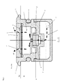
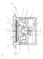
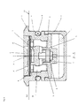
- the Fig. 2 to 5 each show a section AA through the hand tool gear 10 according to the section line AA Fig. 1 , where in the Fig. 2 to 5 each other embodiments are shown.
- the hand tool gear lock 10 in Fig. 1 has a base body 1 for closing a transmission housing opening 70 of a transmission housing 80. By means of a circumferential sealing ring 6 of the base body 1 is peripherally sealed to the gear housing opening 70 back. Furthermore, the hand tool transmission closure 10 has a cover part 2 which has a ventilation opening 2 'on its surface. In the presentation of the Fig. 1 is only the location of the vent 2 'recognizable. An embodiment of the ventilation opening 2 'is for example the Fig. 6 to show a perspective view of the hand tool gear 10 according to the invention.
- the hand tool transmission closure 10 also has an air duct L through which an air mass (not shown) can flow into and out of the transmission housing for the purpose of pressure equalization.
- an air mass not shown
- Fig. 1 Only a portion of the air channel L can be seen, which is formed by an opening hole 1 "in a trough-shaped portion 1 'of the base body 1.
- the hand tool gear 10 has the Fig. 2 a arranged in the air duct L oleophobic membrane 9, which is permeable to air and transmission oil and acts as a pressure compensation element and sealing element.
- the oleophobic membrane 9 is plate-shaped and arranged coaxially with the base body 1.
- the oleophobic membrane 9 is made of plastic and has a pore diameter smaller than 25 microns.
- the hand tool transmission closure 10 further comprises a cover part 2 with ventilation openings 2 ', wherein the oleophobic membrane 9 is held by the cover part 2 against the base body 1.
- the cover part 2 is preferably secured to the base body 1 by means of an adhesive (not shown).
- the oleophobic membrane 9 Underneath the oleophobic membrane 9 is a support body 5, which is enclosed by the hand-held power transmission closure 10 and arranged in the base body 1. By means of the supporting body 5, a deflection of the oleophobic membrane 9 is limited in the course of a pressure equalization, so that the oleophobic membrane 9 is protected from damage.
- the air duct L which extends through the hand tool transmission closure 10, explained in more detail.
- the air channel L extends through the trough-shaped portion 1 'of the base body 1 in the direction of the support body 5.
- the air duct L branches into parallel channel sections formed by a plurality of arranged on the circumference of the support body 5 holes From there, the air channel L extends through a free space 4 "between the base body 1 and the support body 5.
- the ventilation openings 2 'of the cover part 2 in turn form sections of the air channel L of the hand tool transmission closure 10. With the ventilation openings 2' of the cover part 2 ends the air duct L. ,
- FIG. 2 Exemplary is in Fig. 2 the state shown when the transmission pressure DI exceeds the ambient pressure DU, ie in the transmission housing 80, there is an overpressure. This is the case, for example, when the percussion mechanism (not shown) has heated a lubricant located in the transmission housing 80. Pressure compensation takes place via the oleophobic membrane 9.
- a dashed line shows an air mass LM that moves out of the transmission housing 80 in the direction of the arrow through the air duct L hand tool transmission closure 10 due to the transmission internal pressure DI which is greater than the ambient pressure DU.
- the air mass LM first passes through the opening bore 1 ".
- the hand tool transmission closure 10 has a second air-permeable and gear oil-tight sealing element 8.
- the second sealing element 8 is spaced from the oleophobic membrane 9 in the vertical direction, arranged in the air channel L and arranged coaxially with the base body 1.
- the second sealing element 8 consists in the present embodiment of felt and is rotationally symmetrical.
- Fig. 3 now shows the state when the transmission internal pressure DI is lower than the ambient pressure DU, ie in the transmission housing 80, there is a negative pressure.
- This is in Fig. 3 exemplified by a dashed line an air mass LM, which is due to the transmission internal pressure DI, which is smaller than the ambient pressure DU, moves in the direction of arrow through the air duct L hand tool transmission closure 10 in the gear housing 80 inside.
- the air mass LM first passes through the ventilation opening 2 ".
- the Opening bore 1 "of the trough-shaped portion 1 'of the base body 1 enter the transmission housing 80.
- a hand tool gear lock 10 is shown, which both a support body (see. Fig. 2 ) as well as a second sealing element 8 (see. Fig. 3 ) in combination.
- Fig. 5 shows a schematic representation of the hand tool gear 10 of the Fig. 4 , where in Fig. 5 a bi-directional pressure valve 3 is arranged as a second pressure equalization element in the air duct L of the hand tool transmission closure 10, via which both an overpressure occurring in the transmission housing 80, ie DI> DU, and a negative pressure occurring in the transmission housing 80, ie DI ⁇ DU is degradable.
- Fig. 5 the state is shown when transmission internal pressure DI and ambient pressure DU are substantially equal. This is the case, for example, if the hand tool was not in operation for a long time or during operation of the power tool when pressure equalization has already taken place.
- the pressure valve 3 is disposed within the hand tool gear lock 10 and formed as an elastic hose member consisting of silicone.
- the designed as an elastic hose member pressure valve 3 is arranged coaxially to the rotationally symmetrical base body 1 of the hand tool gear lock 10.
- the hand tool transmission closure 10 has a support body 5 arranged in the base body 1, the pressure valve 3 designed as an elastic hose element being supported both against the base body 1 and against the support body 5.
- the pressure valve 3 provided as an elastic hose element is only partially supported on its inner and outer circumference. At the inner circumference, the pressure valve 3 provided as an elastic hose element is supported only on the support body 5, to less than 50 percent of its inner surface. On the outer circumference, the pressure valve 3 provided as an elastic hose element is supported only on the main body 1, to less than 50 percent of its outer surface.
- an outer escape zone 4 and at its inner periphery an inner escape zone 4 ' is formed.
- the elastic hose member formed pressure valve 3 in the course of a Pressure compensation can be deflected unhindered.
- the hose element is on its underside, forming a part of the air channel L, spaced from the base body 1.
- the outer escape zone 4 extends circumferentially to the support body and is arranged coaxially with respect to both the base body 1 and the support body 5.
- the inner escape zone 4 ' runs circumferentially to the support body and is arranged coaxially with respect to both the base body 1 and the support body 5.
- the outer escape zone 4 is defined exclusively by a space between the outer side of the hose element and the main body 1, whereas the inner escape zone 4 'is defined by a space between the inner side of the hose element and the support body 5.
- the support body 5 is conical in its lower region and thus defines, at least in sections, the inner escape zone 4 '.
- Fig. 6 is an exploded view of just with reference to Fig. 4 hand tool gear 10 described. Again Fig. 6 can be removed, the trough-shaped portion 1 ', the sealing ring 6, the base body 1, provided as a felt element second sealing member 8, the support body 5, the plate-shaped oleophobic membrane 9 and the cover part 2 are arranged coaxially to each other.
- Fig. 7 shows the hand tool gear 10 in a schematic and perspective view.
- the opening bore 1 is arranged, through which an air mass LM in the air duct L of the hand tool gear lock 10 (in the event of pressure reduction) enter or (in the case of a negative pressure compensation) can escape.
- FIG Fig. 8 A hand tool 100 according to the invention with a hand tool gear lock 10 is shown in FIG Fig. 8 shown.
- the hand tool 100 has a housing 90 which encloses a gear housing 80.
- a striking mechanism 60 is arranged, which develops heat in the course of operation of the power tool 100.
- a transmission housing opening 70 is arranged, which in the present case is closed by a hand tool transmission closure 10.
- the hand tool gear lock 10 is covered by a swing plate 50.
Landscapes
- Engineering & Computer Science (AREA)
- Mechanical Engineering (AREA)
- General Engineering & Computer Science (AREA)
- General Details Of Gearings (AREA)
Priority Applications (1)
| Application Number | Priority Date | Filing Date | Title |
|---|---|---|---|
| EP15169115.1A EP3098028A1 (fr) | 2015-05-26 | 2015-05-26 | Fermeture d'engrenage de machine-outil portative et machine-outil portative |
Applications Claiming Priority (1)
| Application Number | Priority Date | Filing Date | Title |
|---|---|---|---|
| EP15169115.1A EP3098028A1 (fr) | 2015-05-26 | 2015-05-26 | Fermeture d'engrenage de machine-outil portative et machine-outil portative |
Publications (1)
| Publication Number | Publication Date |
|---|---|
| EP3098028A1 true EP3098028A1 (fr) | 2016-11-30 |
Family
ID=53191597
Family Applications (1)
| Application Number | Title | Priority Date | Filing Date |
|---|---|---|---|
| EP15169115.1A Withdrawn EP3098028A1 (fr) | 2015-05-26 | 2015-05-26 | Fermeture d'engrenage de machine-outil portative et machine-outil portative |
Country Status (1)
| Country | Link |
|---|---|
| EP (1) | EP3098028A1 (fr) |
Cited By (3)
| Publication number | Priority date | Publication date | Assignee | Title |
|---|---|---|---|---|
| EP4039414A1 (fr) * | 2021-02-09 | 2022-08-10 | Hilti Aktiengesellschaft | Mécanisme à percussion électropneumatique |
| CN116887952A (zh) * | 2021-03-15 | 2023-10-13 | Abb瑞士股份有限公司 | 泄压部件、齿轮箱和机器人 |
| DE102024106452A1 (de) * | 2024-03-06 | 2025-09-11 | Carl Freudenberg Kg | Druckausgleichsvorrichtung und deren Verwendung |
Citations (8)
| Publication number | Priority date | Publication date | Assignee | Title |
|---|---|---|---|---|
| US3367447A (en) * | 1965-10-01 | 1968-02-06 | Skil Corp | Lubricating system for power tools |
| US5125428A (en) * | 1988-07-21 | 1992-06-30 | Zahnradfabrik Friedrichshafen Ag | Device for equalizing pressure between machine housing and the surroundings |
| US5730183A (en) * | 1995-06-29 | 1998-03-24 | Andreas Stihl | Valve for venting a container |
| US20090029641A1 (en) * | 2005-05-18 | 2009-01-29 | Nitto Denko Corporation | Ventilation member and vented housing using the same |
| JP2010036260A (ja) * | 2008-07-31 | 2010-02-18 | Hitachi Koki Co Ltd | 携帯用工具 |
| EP2281662A2 (fr) * | 2009-08-05 | 2011-02-09 | Makita Corporation | Outil électrique |
| US20120061393A1 (en) * | 2009-05-20 | 2012-03-15 | Makita Corporation | Power tool |
| US20140318374A1 (en) * | 2011-11-28 | 2014-10-30 | Nitto Denko Corporation | Ventilation member |
-
2015
- 2015-05-26 EP EP15169115.1A patent/EP3098028A1/fr not_active Withdrawn
Patent Citations (8)
| Publication number | Priority date | Publication date | Assignee | Title |
|---|---|---|---|---|
| US3367447A (en) * | 1965-10-01 | 1968-02-06 | Skil Corp | Lubricating system for power tools |
| US5125428A (en) * | 1988-07-21 | 1992-06-30 | Zahnradfabrik Friedrichshafen Ag | Device for equalizing pressure between machine housing and the surroundings |
| US5730183A (en) * | 1995-06-29 | 1998-03-24 | Andreas Stihl | Valve for venting a container |
| US20090029641A1 (en) * | 2005-05-18 | 2009-01-29 | Nitto Denko Corporation | Ventilation member and vented housing using the same |
| JP2010036260A (ja) * | 2008-07-31 | 2010-02-18 | Hitachi Koki Co Ltd | 携帯用工具 |
| US20120061393A1 (en) * | 2009-05-20 | 2012-03-15 | Makita Corporation | Power tool |
| EP2281662A2 (fr) * | 2009-08-05 | 2011-02-09 | Makita Corporation | Outil électrique |
| US20140318374A1 (en) * | 2011-11-28 | 2014-10-30 | Nitto Denko Corporation | Ventilation member |
Cited By (4)
| Publication number | Priority date | Publication date | Assignee | Title |
|---|---|---|---|---|
| EP4039414A1 (fr) * | 2021-02-09 | 2022-08-10 | Hilti Aktiengesellschaft | Mécanisme à percussion électropneumatique |
| WO2022171322A1 (fr) * | 2021-02-09 | 2022-08-18 | Hilti Aktiengesellschaft | Mécanisme de percussion électropneumatique |
| CN116887952A (zh) * | 2021-03-15 | 2023-10-13 | Abb瑞士股份有限公司 | 泄压部件、齿轮箱和机器人 |
| DE102024106452A1 (de) * | 2024-03-06 | 2025-09-11 | Carl Freudenberg Kg | Druckausgleichsvorrichtung und deren Verwendung |
Similar Documents
| Publication | Publication Date | Title |
|---|---|---|
| EP3458739B1 (fr) | Amortisseur de vibrations dont la force d'amortissement est fonction de la course | |
| DE102014215563A1 (de) | Dämpfventil | |
| DE102011102537A1 (de) | Feder- und/oder Dämpfervorrichtung | |
| DE112012000764B4 (de) | Dämpfungsanordnung zur Dämpfung/Tilgung von unerwünschten Druckschwingungen in einer hydraulischen Strecke | |
| EP3221230B1 (fr) | Fermeture d'entraînement de machine-outil manuelle et machine-outil manuelle | |
| DE102017215596A1 (de) | Dämpfventil für einen Schwingungsdämpfer | |
| DE102013003405A1 (de) | Überströmventil | |
| DE102016218378A1 (de) | Dämpfventil für einen Schwingungsdämpfer | |
| DE102016117091A1 (de) | Selbstreinigungsmechanismus für pneumatischen Zentralausrücker | |
| EP3221091B1 (fr) | Fermeture d'entraînement de machine-outil manuelle et machine-outil manuelle | |
| DE102020214751A1 (de) | Schwingungsdämpfer mit außenliegenden Steuerventilen | |
| EP3098029A1 (fr) | Fermeture d'engrenage de machine-outil portative et machine-outil portative | |
| DE102010031037B4 (de) | Schwingungsdämpfer mit frequenzselektiver Dämpfkraft | |
| DE102016218371A1 (de) | Dämpfventil für einen Schwingungsdämpfer | |
| DE102008057924B4 (de) | Vorrichtung zur Entlüftung eines Maschinengehäuses sowie Maschinengehäuse | |
| DE102020116049B4 (de) | Entlüftungsvorrichtung | |
| DE1142471B (de) | Kolben fuer hydraulische Teleskopschwingungsdaempfer, insbesondere von Kraftfahrzeugen | |
| DE3018364C2 (de) | Ventilvorrichtung zur Be- und/oder Entlüftung von Gehäusen | |
| DE102020200730B3 (de) | Dämpfventil für einen Schwingungsdämpfer | |
| DE202019004792U1 (de) | Entlüftungsventil, insbesondere für Getriebe | |
| DE102014204739A1 (de) | Schwingungsdämpfer mit einer temperaturabhängig veränderbaren Bypassöffnung | |
| DE102019133665A1 (de) | Ventil und Vorrichtung zur Regelung von Drücken eines Strömungsmittels | |
| DE102022108530A1 (de) | Getriebegehäuse | |
| DE102010010725A1 (de) | Hydraulisches Spannelement mit einer Entlüftungsvorrichtung | |
| DE202016101761U1 (de) | Dämpfungsvorrichtung |
Legal Events
| Date | Code | Title | Description |
|---|---|---|---|
| PUAI | Public reference made under article 153(3) epc to a published international application that has entered the european phase |
Free format text: ORIGINAL CODE: 0009012 |
|
| AK | Designated contracting states |
Kind code of ref document: A1 Designated state(s): AL AT BE BG CH CY CZ DE DK EE ES FI FR GB GR HR HU IE IS IT LI LT LU LV MC MK MT NL NO PL PT RO RS SE SI SK SM TR |
|
| AX | Request for extension of the european patent |
Extension state: BA ME |
|
| STAA | Information on the status of an ep patent application or granted ep patent |
Free format text: STATUS: THE APPLICATION IS DEEMED TO BE WITHDRAWN |
|
| 18D | Application deemed to be withdrawn |
Effective date: 20170531 |