EP3098083A1 - Druckvorrichtung und-platte - Google Patents
Druckvorrichtung und-platte Download PDFInfo
- Publication number
- EP3098083A1 EP3098083A1 EP16000985.8A EP16000985A EP3098083A1 EP 3098083 A1 EP3098083 A1 EP 3098083A1 EP 16000985 A EP16000985 A EP 16000985A EP 3098083 A1 EP3098083 A1 EP 3098083A1
- Authority
- EP
- European Patent Office
- Prior art keywords
- sheet
- ink
- platen
- supporting portions
- printhead
- Prior art date
- Legal status (The legal status is an assumption and is not a legal conclusion. Google has not performed a legal analysis and makes no representation as to the accuracy of the status listed.)
- Granted
Links
Images











Classifications
-
- B—PERFORMING OPERATIONS; TRANSPORTING
- B41—PRINTING; LINING MACHINES; TYPEWRITERS; STAMPS
- B41J—TYPEWRITERS; SELECTIVE PRINTING MECHANISMS, i.e. MECHANISMS PRINTING OTHERWISE THAN FROM A FORME; CORRECTION OF TYPOGRAPHICAL ERRORS
- B41J2/00—Typewriters or selective printing mechanisms characterised by the printing or marking process for which they are designed
- B41J2/005—Typewriters or selective printing mechanisms characterised by the printing or marking process for which they are designed characterised by bringing liquid or particles selectively into contact with a printing material
- B41J2/01—Ink jet
-
- B—PERFORMING OPERATIONS; TRANSPORTING
- B41—PRINTING; LINING MACHINES; TYPEWRITERS; STAMPS
- B41J—TYPEWRITERS; SELECTIVE PRINTING MECHANISMS, i.e. MECHANISMS PRINTING OTHERWISE THAN FROM A FORME; CORRECTION OF TYPOGRAPHICAL ERRORS
- B41J11/00—Devices or arrangements of selective printing mechanisms, e.g. ink-jet printers or thermal printers, for supporting or handling copy material in sheet or web form
- B41J11/0065—Means for printing without leaving a margin on at least one edge of the copy material, e.g. edge-to-edge printing
-
- B—PERFORMING OPERATIONS; TRANSPORTING
- B41—PRINTING; LINING MACHINES; TYPEWRITERS; STAMPS
- B41J—TYPEWRITERS; SELECTIVE PRINTING MECHANISMS, i.e. MECHANISMS PRINTING OTHERWISE THAN FROM A FORME; CORRECTION OF TYPOGRAPHICAL ERRORS
- B41J11/00—Devices or arrangements of selective printing mechanisms, e.g. ink-jet printers or thermal printers, for supporting or handling copy material in sheet or web form
- B41J11/0085—Using suction for maintaining printing material flat
-
- B—PERFORMING OPERATIONS; TRANSPORTING
- B41—PRINTING; LINING MACHINES; TYPEWRITERS; STAMPS
- B41J—TYPEWRITERS; SELECTIVE PRINTING MECHANISMS, i.e. MECHANISMS PRINTING OTHERWISE THAN FROM A FORME; CORRECTION OF TYPOGRAPHICAL ERRORS
- B41J11/00—Devices or arrangements of selective printing mechanisms, e.g. ink-jet printers or thermal printers, for supporting or handling copy material in sheet or web form
- B41J11/02—Platens
-
- B—PERFORMING OPERATIONS; TRANSPORTING
- B41—PRINTING; LINING MACHINES; TYPEWRITERS; STAMPS
- B41J—TYPEWRITERS; SELECTIVE PRINTING MECHANISMS, i.e. MECHANISMS PRINTING OTHERWISE THAN FROM A FORME; CORRECTION OF TYPOGRAPHICAL ERRORS
- B41J11/00—Devices or arrangements of selective printing mechanisms, e.g. ink-jet printers or thermal printers, for supporting or handling copy material in sheet or web form
- B41J11/02—Platens
- B41J11/06—Flat page-size platens or smaller flat platens having a greater size than line-size platens
-
- B—PERFORMING OPERATIONS; TRANSPORTING
- B41—PRINTING; LINING MACHINES; TYPEWRITERS; STAMPS
- B41J—TYPEWRITERS; SELECTIVE PRINTING MECHANISMS, i.e. MECHANISMS PRINTING OTHERWISE THAN FROM A FORME; CORRECTION OF TYPOGRAPHICAL ERRORS
- B41J11/00—Devices or arrangements of selective printing mechanisms, e.g. ink-jet printers or thermal printers, for supporting or handling copy material in sheet or web form
- B41J11/36—Blanking or long feeds; Feeding to a particular line, e.g. by rotation of platen or feed roller
-
- B—PERFORMING OPERATIONS; TRANSPORTING
- B41—PRINTING; LINING MACHINES; TYPEWRITERS; STAMPS
- B41J—TYPEWRITERS; SELECTIVE PRINTING MECHANISMS, i.e. MECHANISMS PRINTING OTHERWISE THAN FROM A FORME; CORRECTION OF TYPOGRAPHICAL ERRORS
- B41J11/00—Devices or arrangements of selective printing mechanisms, e.g. ink-jet printers or thermal printers, for supporting or handling copy material in sheet or web form
- B41J11/66—Applications of cutting devices
-
- B—PERFORMING OPERATIONS; TRANSPORTING
- B41—PRINTING; LINING MACHINES; TYPEWRITERS; STAMPS
- B41J—TYPEWRITERS; SELECTIVE PRINTING MECHANISMS, i.e. MECHANISMS PRINTING OTHERWISE THAN FROM A FORME; CORRECTION OF TYPOGRAPHICAL ERRORS
- B41J13/00—Devices or arrangements of selective printing mechanisms, e.g. ink-jet printers or thermal printers, specially adapted for supporting or handling copy material in short lengths, e.g. sheets
- B41J13/10—Sheet holders, retainers, movable guides, or stationary guides
-
- B—PERFORMING OPERATIONS; TRANSPORTING
- B41—PRINTING; LINING MACHINES; TYPEWRITERS; STAMPS
- B41J—TYPEWRITERS; SELECTIVE PRINTING MECHANISMS, i.e. MECHANISMS PRINTING OTHERWISE THAN FROM A FORME; CORRECTION OF TYPOGRAPHICAL ERRORS
- B41J2/00—Typewriters or selective printing mechanisms characterised by the printing or marking process for which they are designed
- B41J2/005—Typewriters or selective printing mechanisms characterised by the printing or marking process for which they are designed characterised by bringing liquid or particles selectively into contact with a printing material
- B41J2/01—Ink jet
- B41J2/17—Ink jet characterised by ink handling
- B41J2/1721—Collecting waste ink; Collectors therefor
-
- B—PERFORMING OPERATIONS; TRANSPORTING
- B41—PRINTING; LINING MACHINES; TYPEWRITERS; STAMPS
- B41J—TYPEWRITERS; SELECTIVE PRINTING MECHANISMS, i.e. MECHANISMS PRINTING OTHERWISE THAN FROM A FORME; CORRECTION OF TYPOGRAPHICAL ERRORS
- B41J2/00—Typewriters or selective printing mechanisms characterised by the printing or marking process for which they are designed
- B41J2/005—Typewriters or selective printing mechanisms characterised by the printing or marking process for which they are designed characterised by bringing liquid or particles selectively into contact with a printing material
- B41J2/01—Ink jet
- B41J2/17—Ink jet characterised by ink handling
- B41J2/175—Ink supply systems ; Circuit parts therefor
-
- B—PERFORMING OPERATIONS; TRANSPORTING
- B41—PRINTING; LINING MACHINES; TYPEWRITERS; STAMPS
- B41J—TYPEWRITERS; SELECTIVE PRINTING MECHANISMS, i.e. MECHANISMS PRINTING OTHERWISE THAN FROM A FORME; CORRECTION OF TYPOGRAPHICAL ERRORS
- B41J2/00—Typewriters or selective printing mechanisms characterised by the printing or marking process for which they are designed
- B41J2/22—Typewriters or selective printing mechanisms characterised by the printing or marking process for which they are designed characterised by selective application of impact or pressure on a printing material or impression-transfer material
- B41J2/23—Typewriters or selective printing mechanisms characterised by the printing or marking process for which they are designed characterised by selective application of impact or pressure on a printing material or impression-transfer material using print wires
- B41J2/235—Print head assemblies
-
- B—PERFORMING OPERATIONS; TRANSPORTING
- B41—PRINTING; LINING MACHINES; TYPEWRITERS; STAMPS
- B41J—TYPEWRITERS; SELECTIVE PRINTING MECHANISMS, i.e. MECHANISMS PRINTING OTHERWISE THAN FROM A FORME; CORRECTION OF TYPOGRAPHICAL ERRORS
- B41J2/00—Typewriters or selective printing mechanisms characterised by the printing or marking process for which they are designed
- B41J2/005—Typewriters or selective printing mechanisms characterised by the printing or marking process for which they are designed characterised by bringing liquid or particles selectively into contact with a printing material
- B41J2/01—Ink jet
- B41J2/17—Ink jet characterised by ink handling
- B41J2/1721—Collecting waste ink; Collectors therefor
- B41J2/1742—Open waste ink collectors, e.g. ink receiving from a print head above the collector during borderless printing
Definitions
- the present invention relates to an inkjet printing apparatus provided with a platen for supporting a sheet.
- Japanese Patent Laid-Open No. 2006-021475 discloses an ink jet printing apparatus capable of forming an image without a margin at a sheet end, that is, performing so-called "marginless printing.”
- the apparatus uses a suction platen that sucks a sheet by a negative pressure.
- An object of the present invention is to provide a printing apparatus capable of suppressing floating or flexure of a sheet so as to obtain an image of a high quality in marginless printing.
- Another object of the present invention is to provide a printing apparatus capable of securely performing four-side marginless printing with respect to a cut sheet, and a platen.
- the present invention in its first aspect provides a printing apparatus as specified in claims 1 to 12.
- the present invention in its second aspect provides a platen as specified in claim 13.
- an inkjet printing apparatus of a serial type for performing printing by reciprocating a printhead capable of ejecting ink in a direction transverse a sheet conveyance direction with respect to a sheet that is intermittently conveyed in a predetermined direction.
- the present invention is applicable to not only a printing apparatus of a serial type but also a line printing apparatus for sequentially performing printing by the use of an elongated printhead.
- the printing apparatus is applicable to not only a printing apparatus having a single function but also a multiple function printer equipped with a copying function, a facsimile function, and the like.
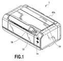
- Fig. 1 is a perspective view showing the outer appearance of a printing apparatus 1 in an embodiment.
- a discharge tray 12 for supporting a printed sheet is provided, and furthermore, a console panel 1a for performing various setting operations and a display 1b are disposed.
- a top cover 1c for covering the inside structure such as a carriage, described later, is openably disposed at the top of the printing apparatus 1, and furthermore, a feed tray 5 for stacking thereon sheets to be fed to a feeder 40, described later, is openably disposed at the back of the printing apparatus 1.
- Fig. 1 shows a state in which the discharge tray 12 and the feed tray 40a are closed, both of the trays 12 and 40a can be opened during a printing operation, as shown in Fig. 2 .
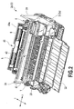
- Fig. 2 is a perspective view showing the entire configuration of the printing apparatus body 1A in which a jacket is detached from the printing apparatus 1; and Fig. 3 is a vertical side view showing the printing apparatus body 1A shown in Fig. 2 .
- the feeder 40 is disposed at the back of the printing apparatus body 1A.
- the feeder 40 separates a bundle of cut sheets (hereinafter simply referred to as sheets) stacked on the feed tray 5 one by one according to the rotation of a feed roller 6, and then, feeds them to a conveyor such as a conveyance roller 7.
- a carriage 4 mounting thereon a printhead 3 capable of ejecting ink is disposed at the printing apparatus body 1A.
- the carriage 4 is supported in a freely reciprocating manner along a carriage guide shaft 41 and a carriage rail 42 disposed in a direction (i.e., an X direction) transverse (perpendicularly in the embodiment) to a sheet conveyance direction (i.e., a Y direction).
- the movement of the carriage 4 and the printhead 3 in the X direction will also be referred to as scanning in the following description.
- the X direction represents the carriage movement direction, and furthermore, is a sheet widthwise direction of the sheet to be conveyed.
- the Y direction represents the sheet conveyance direction.
- One sheet separated and fed from the bundle of sheets stacked on the feed tray 40a by the feeder 40 is conveyed onto a platen 9 supporting the sheet in a manner facing the printhead 3 by a first conveyance roller pair (i.e., the conveyor) including the conveyance roller 7 and a pinch roller 8.
- a first conveyance roller pair i.e., the conveyor
- the carriage 4 mounting the printhead 3 thereon is moved in the X direction, and then, ink is ejected toward the sheet from the printhead 3.
- a sheet detecting sensor for detecting the end of the sheet is disposed on one side surface of the carriage 4. The relative position between the sheet and the printhead and a print starting timing with respect to the sheet are determined based on a detection output from the sheet detecting sensor.
- the sheet Upon completion of printing of one scanning with respect to the sheet, the sheet is conveyed by a predetermined distance in the Y direction perpendicular to the X direction by the first conveyance roller pair.
- the repetition of the scanning of the printhead 3 and the conveyance of the sheet achieves serial printing on the sheet in a serial printing system.
- a printed sheet is discharged onto the discharge tray 12 by a second conveyance roller pair (i.e., a conveyor) including discharge rollers 10 and a pulley 11 disposed downstream of the platen 9 in the sheet conveyance direction (i.e., the Y direction).
- a second conveyance roller pair i.e., a conveyor
- discharge rollers 10 and a pulley 11 disposed downstream of the platen 9 in the sheet conveyance direction (i.e., the Y direction).
- the above-described feeder 40, carriage guide shaft 41, carriage rail 42, and platen 9 are securely supported by a chassis 28 that forms the frame of the printing apparatus body 1A.
- other members including the above-described discharge tray 12, top cover 1c, and feed tray 5 are supported by the chassis 28.
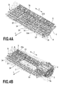
- FIGs. 4A and 4B are perspective views showing the platen 9 and its peripheral structure.
- the platen 9 is interposed between the first conveyance roller pair including the conveyance roller 7 and the pinch roller 8 and the second conveyance roller pair including the discharge rollers 10 and the pulley 11.
- the platen 9 supports the sheet to be conveyed by the first and second conveyance roller pairs on a side (i.e., a reverse) opposite to a side to be printed.
- the platen 9 for use in the printing apparatus 1.
- the platen 9 is interposed between the first conveyance roller pair including the conveyance roller 7 and the pinch roller 8 and the second conveyance roller pair including the discharge rollers 10 and the pulley 11.
- the platen 9 is disposed at a position facing an ejection port forming face 3a of the printhead 3 having ejection ports for ejecting ink arranged thereat.
- the platen 9 supports the surface (i.e., the reverse) of the sheet 2, which is conveyed by the first and second conveyance roller pairs, opposite to a surface to be printed facing the ejection port forming face 3a (see Fig. 2 ).
- the platen 9 is provided with at least one sheet supporting portion 14 (i.e., a first supporting portion) capable of supporting the reverse of the sheet while suppressing floating or flexure of the sheet 2 in order to properly keep an interval between the ejection port forming face 3a of the printhead 3 and the sheet 2.
- the plurality of sheet supporting portions 14 are arranged in a longitudinal direction (i.e., the X direction) of the platen 9 so as to cope with a plurality of kinds of sheet width sizes.
- the sheet supporting portion 14 is disposed in such a manner as not to be positioned within a range of about 2 mm from the side end of the sheet during the conveyance of each of the sheets.
- the arrangement and shape of the sheet supporting portion 14 are determined according to the sheet width of each of types such as an L size, a KG size, a 2L size, a 6P size, a letter size, an A4 size, a 4P size, an A3 size, an A3 elongation size, an HP size, an A2 size, an A2 elongation size, and a 17-inch size.
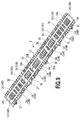
- Fig. 5 is a perspective view showing the general configuration of the platen 9.
- the platen 9 is provided with the sheet supporting portion 14 (i.e., the first supporting portion) capable of supporting the reverse of the sheet 2 while suppressing floating or flexure of the sheet 2 in order to properly keep the interval between the ejection port forming face 3a of the printhead 3 and the sheet 2.
- the plurality of sheet supporting portions 14 are formed in the longitudinal direction (i.e., the X direction) of the platen 9.
- Fig. 6 is an enlarged view partly showing the platen 9 shown in Fig. 5 .
- the sheet supporting portion 14 is formed into a rectangular frame with a projecting portion.
- a sheet supporting surface 13 of the supporting portion 14 has a width of about several millimeters.
- a suction recess 17 is formed at the upper portion of the sheet supporting portion 14, thereby forming a recess lower by one step than the sheet supporting surface 13.
- Suction holes (i.e., suction units) 18 are formed at the bottom surface of the suction recess 17 in such a manner as to penetrate the platen 9.
- the suction holes 18 communicate with a negative pressure generator 19, described later.
- a negative pressure generated by the negative pressure generator 19 is supplied to the suction recess 17 through the suction holes 18.
- the sheet passing the sheet supporting surface 13 is sucked by the negative pressure supplied to the suction recess 17, and then, is sucked to the sheet supporting surface 13. In this manner, the sheet 2 is conveyed while being kept flat without any flexure or floating. Consequently, a distance (i.e., a distance to a sheet) between the ejection port forming surface 3a of the printhead 3 and the sheet 2 is kept at a preset proper distance.
- ink is ejected to the outside of the sheet immediately before a printing operation, that is, preliminary ejection is performed in order to stabilize ink ejection performance of the printhead 3.
- preliminary ejection is performed in order to stabilize ink ejection performance of the printhead 3.
- a leading end ink discarding groove i.e., a first ink receiver
- a trailing end ink discarding groove i.e., a second ink receiver
- Fig. 7 is a vertical side view partly showing the platen 9.
- Fig. 7 shows the cross sections of the leading end ink discarding groove 31A and trailing end ink discarding groove 31B of the platen 9.
- the leading end ink discarding groove 31A is elongated in the X direction downstream of the sheet supporting portion 14 whereas the trailing end ink discarding groove 31B is elongated in the X direction upstream of the sheet supporting portion 14.
- the leading end ink discarding groove 31A includes a bottom 31a lower than the sheet supporting surface 13, a downstream wall 31d of the sheet supporting portion 14, and a side wall 31e of a downstream sheet supporting portion 33.
- the trailing end ink discarding groove 31B includes a bottom 31a lower than the sheet supporting surface 13, an upstream wall 31c of the sheet supporting portion 14, and a side wall 31b of an upstream sheet supporting portion 32.
- the leading end ink discarding groove 31A and the trailing end ink discarding groove 31B have a capacity enough to prevent the ink from overflowing in a case where they receive the ink ejected from the printhead 3.
- the platen has right/left end ink discarding grooves (i.e., a third ink receiver) 34 according to the width of the sheet in such a manner as to receive the ink ejected to the outside of the sheet side end (see Fig. 8 ).
- the sheets that can be subjected to marginless printing have mainly standard sizes such as an L size, a 2L size, a postcard size, an A4 size, a letter size, an A3 size, a legal size, and an A2 size.
- the plurality of ink discarding grooves 34 are formed at positions corresponding to the right and left ends of the sheet according to the sizes of sheets.
- the leading end ink discarding groove 31A, the trailing end ink discarding groove 31B, and the right/left end ink discarding grooves 34 are formed in a grid pattern at the obverse of the platen 9, thus surrounding the sheet supporting portion 14.
- the arrangement of the sheet supporting portion 14 is determined with reference to a print position.
- the reference of the print position is set at the center of the width of a print sheet: namely, a so-called center reference sheet supply is adopted.
- the sheet is conveyed such that the center of the sheet width (i.e., a print width) matches the center of the platen 9 in the widthwise direction in a case where the sheet has any one of various sheet widths.
- the sheet supporting portion 14 is symmetrically disposed such that the right/left end ink discarding grooves 34 are formed at symmetric positions with reference to the center position of the width of the platen 9 in the X direction.
- one side of the right/left end ink discarding groove 34 should be positioned inward by about 2 mm of the right or left end of the sheet whereas the other side thereof should be positioned outward by about 5 mm of the end of the sheet.
- the width of the ink discarding groove and the position of the sheet supporting portion are determined in such a manner as to satisfy the above-described positional relationship with respect to the various kinds of sheets having the standard sizes.
- a one-side reference may be adopted such that all sheets having various kinds of sizes are aligned at one of right and left reference positions.
- Fig. 8 is a view showing sheet supporting portions corresponding to the sheets of A4 and A3 sizes, for example. Since the center reference is adopted, as described above, the centers of the sheets having different sizes pass one center reference 2d set on the platen 9 all the time. In a case where a sheet of an A4 size is conveyed in the longitudinal direction of the sheet, the end of the sheet passes a position apart by 105 mm in the X direction from the center reference 2d of the platen 9. In view of this, the sheet supporting portion 14 is arranged such that the right/left end ink discarding groove 34 is formed within a range apart by 103 mm to 110 mm from the center reference 2d.
- the sheet supporting portion 14 is arranged such that the right/left end ink discarding groove 34 is formed within a range apart by 146.5 mm to 153.5 mm from the center reference 2d.
- the number of right/left end ink discarding grooves 34 is halved in the case of not the center reference but the one-side reference, and furthermore, the distance from a reference position is changed.
- first to sixth sheet supporting portions (14A to 14F) having different sizes are formed to cope with a plurality of kinds of sheets having different sheet widths (i.e., sizes of sheets in the X direction) (see Figs. 5 and 9 ).
- each of the first sheet supporting portion 14A to the fifth sheet supporting portion 14E has the suction recess 17 having a relatively large area, and therefore, the suction holes 18 are formed thereat, as described above.
- the area of the suction recess 17 is small at the smallest sixth sheet supporting portion 14F, and therefore, no suction hole 18 is formed.
- the sheet supporting portion 14F copes with a sheet of a 2L size and a sheet of an HP size, and no suction hole 18 is formed at the suction recess 17 of each of the sheet supporting portions 14F.
- intermediate ribs 14r each having the same height as that of the sheet supporting surface 13, are formed in the direction perpendicular to the X direction (i.e., the Y direction) in such a manner as to prevent the sheet from denting at the suction recess 17.
- three intermediate ribs 14r are formed at each of the first sheet supporting portion 14A and the second sheet supporting portion 14B; and two intermediate ribs 14r are formed at the third sheet supporting portion 14C.
- the upper surface of the intermediate rib 14r has a support surface flush with the sheet supporting surface 13 formed into a frame.
- the fifth and sixth sheet supporting portions 14E and 14F have no intermediate rib 14r. It is desirable that the number of suction holes 18, the diameter of the suction hole 18, the number of intermediate ribs 14r, and the like should be appropriately determined according to the sizes of the sheet supporting portion 14 and the suction recess that are determined according to the corresponding sheet sizes.
- the sheet supporting portion 14 of the platen 9 is individually surrounded by the fore and trailing end ink discarding grooves 31A and 31B and the right/left end ink discarding grooves 34.
- an ink absorber 35 is disposed at each of the ink discarding grooves 31A, 31B, and 34, as shown in Figs. 7 and 9 . It is preferable that the ink absorber 35 should be a spongy single sheet made of expanded urethane. The upper surface of the ink absorber 35 is locked by a plurality of lock claws 38 (see Fig. 8 ), so that the ink absorber 35 can be inhibited from being detached.
- the platen 9 is provided with an outer peripheral wall 20 that surrounds the sheet supporting portion 14 including the suction holes 18 and the ink discarding grooves 31A and 31B.
- the outer peripheral wall 20 forms a casing (i.e., a platen casing).
- a waste ink discharge port 30 communicating with the ink discarding grooves 31A and 31B. Waste ink discarded into each of the ink discarding grooves 31A and 31B is discharged to the outside of the platen 9 through the waste ink discharge port 30.
- the first ink receiver and the second ink receiver are connected to each other via the third ink receivers.
- each of the plurality of supporting portions is individually surrounded by the first ink receiver, the second ink receiver, and the third ink receivers. Therefore, the waste ink received in these three ink receivers is collected at one site, and then, can be discharged through the common ink discharge port 30.
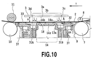
- Fig. 10 is a vertical side view showing an air channel disposed at the upstream and downstream sheet supporting portions 32 and 33.
- the upstream sheet supporting portion 32 for supporting the sheet conveyed by the conveyance roller 7 at the reverse thereof is formed at the platen 9 further upstream of the trailing end ink discarding groove 31B.
- the downstream sheet supporting portion 33 for supporting the sheet conveyed by the discharge roller 10 at the reverse thereof is formed at the platen 9 further downstream of the leading end ink discarding groove 31A.
- the upstream sheet supporting portion 32 and the downstream sheet supporting portion 33 each are ribbed projections extending in the sheet conveyance direction (i.e., the Y direction).
- the plurality of upstream sheet supporting portions 32 and the plurality of downstream sheet supporting portions 33 are arranged at predetermined intervals in the X direction, as shown in Fig. 6 .
- each of the upstream sheet supporting portion 32 and the downstream sheet supporting portion 33 is formed in the same height as that of the sheet supporting surface (i.e., a contact portion) 13 of the sheet supporting portion 14.
- the upstream sheet supporting portion 32 and the downstream sheet supporting portion 33 fulfill the function of preventing the sheet 2 from denting or being involved at the sheet supporting portion 14 or each of the rollers in a case where the fore or trailing end of the sheet 2 passes there.
- the adjacent upstream sheet supporting portions 32 are connected to each other via a connection seat 37 at the lower portions thereof (see Figs. 6 and 10 ).
- a clearance is formed between a passing sheet and the connection seat 37 (see Fig. 10 ).
- the adjacent downstream sheet supporting portions 32 are connected to each other via the connection seat 37.
- a clearance is formed between the sheet 2 supported by the downstream sheet supporting portions 32 and the connection seat 37. Therefore, as indicated by a broken arrow A in Fig. 10 , an air channel is formed in such a manner as to introduce fresh air from the outside of the platen 9 toward the ink discarding groove 31B.
- a notch 39 is formed at a part of the connection seat 37, as shown in Fig.
- an air channel for enabling air to flow in also is formed in a direction perpendicular to the reverse of the sheet, as indicated by a broken arrow B.
- the conveyance roller 7 is a cylindrical roller in which the entire surface thereof is covered with rubber or coating particles in most cases, a closed space is liable to be defined by the sheet 2 to be conveyed, the conveyance roller 7, the connection seal 37 of the platen 9.
- the formation of the notch 39 for enabling the air to flow in defines a clearance between the sheet 2 and the upstream sheet supporting portion 32, thus enabling a greater quantity of fresh air to be supplied toward the ink discarding grooves 31A, 31B, and 34 at the platen 9.
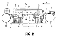
- Fig. 11 is a view showing the positional relationship between the ejection port of the printhead 3 and the sheet supporting portion 14 at the beginning of the printing operation.
- Fig. 12 is a view showing the positional interrelationship between the trailing end of the sheet 2, the ejection port of the printhead 3, and the sheet supporting portion 14 at the end of the printing operation.
- the sheet 2 is conveyed up to a position at which the sheet supporting surface 13 is completely covered at the beginning of the printing operation.
- the sheet supporting surface 13 is completely covered with the sheet 2, so that a stable negative pressure can be generated at the suction recess 17. Since the sheet can be sucked even if the sheet 2 is slightly misaligned, the sheet is conveyed up to a position slightly off the sheet supporting portion 13.
- the length of an ejection port array having a plurality of ejection ports arrayed thereat is determined as follows: namely, as shown in Figs. 11 and 12 , an ejection port array 3b of the printhead 3 is formed within a range completely encompassing the sheet supporting portion 14 in the sheet conveyance direction (i.e., the Y direction). Consequently, a most upstream ejection port 3c at the ejection port array 3b is positioned outside (i.e., upstream) of an upstream end 14a of the sheet supporting portion 14 whereas a most downstream ejection port 3d is positioned outside (i.e., downstream) of a downstream end 14b of the sheet supporting portion 14.
- the sheet 2 is conveyed in such a manner that a leading end 2a or a trailing end 2b is slightly off the sheet supporting portion 14.
- the most downstream ejection port 3d of the printhead 3 is required to be positioned slightly downstream of the leading end 2a of the sheet 2 during printing at the leading end 2a of the sheet 2 ( Fig. 11 ).
- the most upstream ejection port 3c of the printhead 3 is required to be positioned slightly upstream of the trailing end 2b of the sheet 2 during printing at the trailing end 2b of the sheet 2 ( Fig. 12 ).
- an off amount L should be determined in consideration of a dimension at which no margin is produced in expectation of the stoppage position accuracy or dimensional tolerance of the fore or trailing end of the sheet 2.
- An off amount L of about 2 mm is normally set.
- the relationship between the sheet supporting portion 14 and the ejection ports of the printhead 3 is required to be determined, as follows: namely, the upstream end 14a of the sheet supporting portion 14 is positioned downstream of the most upstream ejection port 3c of the printhead 3 in the sheet conveyance direction whereas the downstream end 14b of the sheet supporting portion 14 is positioned upstream of the most downstream ejection port 3d of the printhead 3.
- the ink can be ejected up to a range slightly off the fore and trailing ends 2a and 2b of the sheet 2, so that the marginless printing can be securely performed at the fore and trailing ends 2a and 2b of the sheet 2.
- the sheet 2 In performing the marginless printing at the ends (i.e., the right and left ends) in the sheet widthwise direction, the sheet 2 is supported by the sheet supporting portion 14 disposed in a slightly narrower range than the size of the sheet 2 to be printed. And then, the scanning range of the printhead 3 is determined such that the ink is ejected up to a range slightly off outward (i.e., sideways) of the sheet 2. In this manner, the marginless printing can be performed at the right and left ends of the sheet 2.
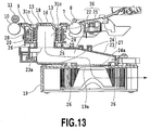
- Fig. 13 is a vertical side view showing a sheet sucking mechanism disposed in the printing apparatus; and Fig. 14 is a perspective view showing the sheet sucking mechanism, as viewed from the bottom.
- the sheet sucking mechanism includes the platen 9, a duct 27 communicating with the suction holes 18 formed at the platen 9, and the negative pressure generator communicating with the duct 27.
- the duct 27 having a cavity therein is formed right under the platen casing formed of the outer peripheral walls 20 of the platen 9, wherein the duct 27 includes a cover member 23 having a first opening 23a formed at the upper surface thereof and a base member 24 having a second opening 24a formed at the lower surface thereof.
- the upper surface of the cover member 23 engages with the bottom of the outer peripheral walls 20 of the platen 9 in such a manner as to include the first opening 23a.
- the second opening 24a formed at the lower surface of the base member 24 engages with a suction port 19a of a suction fan 19 serving as the negative pressure generator.
- an intake channel 36 is formed from the suction holes 18 formed at the platen 9 toward the suction fan 19.
- the intake channel 36 includes a first negative pressure chamber 22 corresponding to a space inside of the platen casing defined by the outer peripheral wall 20 of the platen 9 and a second negative pressure chamber 25 formed inside of the duct 27 including the base member 24 and the cover member 23.
- the base member 24 forming the duct 27 is fixed to a chassis 28.
- the first negative pressure chamber 22 is divided into a plurality of small spaces independent of each other in the sheet widthwise direction in a manner corresponding to the plurality of sheet supporting portions 14.
- Fig. 13 shows one small space.
- the first negative pressure chamber 22 and the second negative pressure chamber 25 are partitioned by the cover member 23.
- the common second negative pressure chamber 25 communicates with the plurality of first negative pressure chambers 22 via the openings 23a of the small spaces.
- a seal member 26 for preventing any leakage of air is disposed at each of an engagement portion between the upper surface of the cover member 23 and the bottom of the outer peripheral wall 20 of the platen 9 and an engagement portion between the second opening 24a of the base member 24 and the suction port 19a of the suction fan 19. It is preferable that the seal member 26 should be formed of soft expanded rubber or the like that has high sealability and is made of EPDM such that the platen 9 or the cover member 23 cannot be deformed by the repulsive force of the seal member 26 at the time of compression.
- the seal member 26 is interposed between members, thus suppressing the transmission of vibrations caused by driving the suction fan 19 to the platen 9 while keeping the sealability between the members so as to suppress an adverse effect on the printing operation.
- the waste ink discharge port 30 at the platen 9 is disposed on the outer peripheral wall 20 of the platen 9, and therefore, the duct 27 disposed right under the platen 9 can occupy the space right under the platen 9 without any inhibition of the arrangement of the waste ink discharge port 30. Consequently, the second negative pressure chamber 25 of the duct 27 can secure a size enough to stabilize the negative pressure generated by the rotation of the suction fan 19, thereby remarkably enhancing the freedom degree of a design.
- the suction fan 19 serving as the negative pressure generator should be a sirocco fan or the like having an excellent suction efficiency.
- the suction air rate of the suction fan 19 can be adjusted under a PWM control. The air rate is variable according to the type, state, and use atmospheric environment of sheet, thereby adjusting the suction of the sheet.
- the suction fan 19 is rotated to discharge the air staying inside of the duct 27, thus bringing the entire intake channel 36 into a negative pressure state, so as to suck the air through the suction holes 18 communicating with the duct 27.
- the platen 9 is molded with a resin into a single component part. All of the sheet supporting portion 14, the upstream sheet supporting portion 32, the downstream sheet supporting portion 33, the plurality of the first negative pressure chambers 22, and the ink receivers (i.e., the first to third ink receivers) are aggregated into a single resin-molded component part that forms the platen 9. In this manner, it is possible to simplify the fabrication of the printing apparatus, and furthermore, enhance the accuracy of relative positions among functional component parts.
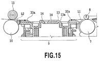
- Fig. 15 is a vertical side view showing the first conveyance roller pair, the second conveyance roller pair, and the platen 9.
- the conveyance roller 7 and the pinch roller 8 forming the first conveyance roller pair are arranged in such a manner that a conveyance roller nip tangent L1 passing a contact point between both of the rollers crosses the sheet supporting surface 32a of the upstream sheet supporting portion 32. Since the first conveyance roller pair is arranged in the above-described manner, the leading end of the sheet conveyed up to a print start position can be securely brought into contact with the sheet supporting surface 13 of the sheet supporting portion 14. As a consequence, it is possible to efficiently generate a negative pressure so as to further securely suck the sheet.
- the discharge roller 10 and the pulley 11 forming the second conveyance roller pair are arranged in such a manner that a discharge roller nip tangent L2 passing a contact point therebetween crosses the sheet supporting surface 33a of the downstream sheet supporting portion 33. Since the second conveyance roller pair is arranged in the above-described manner, the trailing end of the sheet can be brought into contact with the sheet supporting surface 13 at the last moment even after the printing operation, thus keeping a posture in the efficiently sucked state for a longer period of time.
- the fore and trailing ends of the sheet 2 can be efficiently sucked by the sheet supporting surface 13 of the platen 9 in the present embodiment, and thus, the floating of the sheet can be reduced over the entire sheet from the leading end to the trailing end.
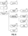
- Fig. 16 is a block diagram illustrating the schematic configuration of a control system of the printing apparatus 1 in the present embodiment.
- a head drive circuit 102 for controlling the ink ejection by the printhead 3.
- a motor drive circuit 103 for controlling motors for actuating the mechanisms (a carriage motor 104, a conveyance roller motor 105, a feed roller motor 106, the suction fan 19, etc.) and the like.
- the motor drive circuit 103 can perform the PWM control, thus adjusting the air rate of the suction fan 19 so as to adjust the suction negative pressure at the sheet sucking mechanism.
- a change in air rate according to the type of sheet, the state of a sheet, and an atmospheric environment condition is effective in adjusting sheet conveyance performance.
- the air rate may be changed according to the position of the carriage 4 and the sheet conveyance position.
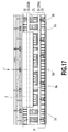
- Fig. 17 is a plan view showing a state in which the leading end of the sheet 2 passes over the sheet supporting portion 14 during the feeding operation by the feeder 40.
- the sheet 2 stacked on the feed tray 5 is fed up to the conveyance roller 7 by the above-described feeder 40, and furthermore, is conveyed up to the platen 9 by the conveyance roller 7.
- the suction fan 19 is started during the feeding of the sheet 2, and thus, a predetermined negative pressure is generated at the duct 27 communicating with the suction holes 18 formed at the platen 9.
- the strength of the negative pressure is controlled under the conditions such as the type of sheet, the state of the sheet, and the atmospheric environment. It is preferable that a stronger negative pressure (i.e., a stronger suction pressure) should be generated in the case of the use of a thick sheet or a largely curled sheet or in low humidity.
- the negative pressure is controlled by the motor drive circuit 103 for controlling the drive of the suction fan 19.
- Various kinds of control systems may be used. For example, the PWM control or the like may be used.
- the sheet 2 Prior to the start of the printing operation, the sheet 2 is conveyed up to a position shown in Fig 18 . That is to say, the leading end 2a of the sheet reaches the sheet supporting portion 14 beyond the ink discarding groove 31 of the upstream sheet supporting portion 32, and then, is conveyed up to a position slightly off the downstream end 14b, where the conveying operation is temporarily stopped. At this time, the sheet 2 comes to a state sucked by the sheet supporting surface 13. During the conveying operation until the sheet 2 comes to the state, the negative pressure is generated inside the suction recess 17, and therefore, the leading end 2a of the sheet 2 is conveyed toward the supporting surface 13 while being sucked.
- Fig. 18 shows the position of the sheet 2 immediately before the printing operation is started. Incidentally, sufficient suction force cannot be exerted on the sheet 2 until 1 the sheet 2 covers the sheet supporting surface 13. However, the sheet 2 is conveyed in the state in which the floating of the leading end 2a is suppressed, and therefore, the sheet 2 can be smoothly conveyed up to a header position.
- an inclined face 13a Fig. 7 ) for guiding the leading end 2a of the sheet 2 toward the sheet supporting surface 13 is formed at the upstream end of the sheet supporting portion 14.
- the leading end 2a of the sheet 2 almost falls downward in a case where the leading end 2a of the sheet 2 passes the ink discarding groove 31B, the leading end 2a is guided to the sheet supporting surface 13 due to the contact with the inclined face 13a, and therefore, the leading end 2a of the sheet 2 can smoothly pass the ink discarding groove 31B.
- the printhead 3 performs reciprocal scanning based on image data, thereby starting the printing operation.
- an image is printed on the sheet 2, and furthermore, the ink is ejected up to a region outside (i.e., downstream) of the leading end 2a of the sheet 2.
- the ink ejected to the region outside of the sheet 2 is discarded into the ink absorber 35 inside of the trailing end ink discarding groove 31B positioned downstream of the sheet supporting portion 14.
- the printing operation is continued by repeating the conveyance of the sheet 2 by the conveyance roller 7 and the discharge roller 10 and the reciprocal scanning by the printhead 3.
- Fig. 19 is a view showing a state in which the middle portion of the sheet 2 is printed.
- the ink is ejected not only on the sheet 2 but also regions outside of the right and left ends of the sheet 2.
- the platen 9 also has the right/left end ink discarding grooves 34 corresponding to the positions of the right and left ends of the sheet 2.
- the ink ejected outside of the right and left ends of the sheet 2 is discarded into the ink absorber 35 inside of the right/left end ink discarding groove 34 positioned outside of the right and left ends of the sheet 2.
- the ink mist generated at this time is thinned with the fresh air introduced through the air channels formed upstream and downstream of the platen 9, thus reducing the adhesion of the ink mist onto the reverse of the sheet.
- the printing operation is further continued, and then, the trailing end 2b of the sheet 2 passes through the first conveyance roller pair (i.e., between the conveyance roller 7 and the pinch roller 8), and thereafter, the sheet 2 is conveyed by the second conveyance roller pair (i.e., the discharge roller 10 and the pulley 11).
- the second conveyance roller pair i.e., the discharge roller 10 and the pulley 11.
- the marginless printing is performed with respect to the trailing end 2b of the sheet 2.
- the ink is ejected onto not only the sheet 2 but also a region outside (upstream) of the trailing end 2b of the sheet 2.
- the ink ejected to the region outside of the trailing end 2b of the sheet 2 is discarded into the ink absorber 35 (i.e., sponge) inside of the trailing end ink discarding groove 31B positioned upstream of the sheet supporting portion 14.
- the printing operation with respect to the trailing end 2b of the sheet 2 comes to an end in the state in which the sheet 2 is sucked by the sheet supporting surface 13.
- the sheet 2 is placed on the sheet supporting surface 13 of the sheet supporting portion 14 all the time from the beginning of the printing operation to the end thereof.
- a proper negative pressure is introduced into the suction recess 17, so that the printing operation can be performed in the state in which the sheet 2 is sucked by the sheet supporting surface 13 all the time.
- the distance H to the sheet (see Fig. 12 ) between the printhead 3 and the sheet 2 can be kept at a predetermined proper distance, thereby accurately printing an image.
- Fig. 21 is a plan view showing a state in which the trailing end 2b of the sheet 2 passes the sheet supporting portion 14. After the completion of the printing operation, the sheet 2 is conveyed by the second conveyance roller pair. At this time, the trailing end 2b of the sheet 2 passes the leading end ink discarding groove 31B while being supported by the downstream sheet supporting portion 33, and then, is discharged onto the discharge tray 12.
- the printing operation can be performed in the same process as the above-described process except the ink ejection to the outside of the sheet.
- the strength of the negative pressure to be generated by the suction fan 19 or the switch of drive or stop of the suction fan 19 is controlled under the print conditions, so that the proper suction force can be exerted on the sheet.
- four-side marginless printing can be performed with respect to a cut sheet.
- the printing operation can be performed while suppressing the floating or flexure of the sheet and properly keeping the clearance between the printhead and the sheet.
- an image of a high quality can be achieved by the marginless printing.
- Figs. 22 and 23 are enlarged perspective views showing the detailed shape of a sheet supporting portion 14 in the second embodiment.
- Fig. 22 is a perspective view partly showing a platen and a sheet
- Fig. 23 is a perspective view showing an air flow at the platen shown in Fig. 22 .
- the sheet supporting portion 14 is obtained by forming, into a rectangular frame, a ribbed projection having a flat sheet supporting surface 13 in contact with the reverse of a sheet.
- a suction recess 17 i.e., a suction unit
- Suction holes 18 i.e., first suction holes penetrating from the obverse of the suction recess 17 to the reverse thereof are formed at the suction recess 17.
- the suction holes 18 communicate with a negative pressure generator 19 via a plurality of first negative pressure chambers 22 defined by outer peripheral walls 20 of a platen 9 and a duct 27 connected to the first negative pressure chambers 22 (see Figs. 13 and 14 in the first embodiment), thus applying a negative pressure generated by the negative pressure generator 19 to the first negative pressure chambers 22 and the suction holes 18.
- intermediate ribs 14r flush with the sheet supporting surface 13 are formed at the suction recess 17. It is desirable that the surface of the intermediate rib 14r should be continuous to the sheet supporting surface 13 and should extend in a sheet conveyance direction (i.e., a Y direction).
- ink receivers that receive ink ejected to the outside of a sheet 2. It is necessary to eject ink up to the outside of the end of the sheet so as to securely perform printing over the entire sheet without any margin at the peripheral edge of the sheet, that is, so-called marginless printing.
- ink is ejected to the outside of the sheet immediately before a printing operation, that is, a so-called preliminary ejection is performed. The above-described ink ejected to the outside of the sheet is received in the ink receivers formed at the platen 9.
- the ink receivers include a leading end ink discarding groove 31A that receives ink ejected to the outside of a sheet leading end 2a and a trailing end ink discarding groove 31B that receives ink ejected to the outside of a sheet trailing end 2b.
- the leading end ink discarding groove 31A is elongated in an X direction adjacently downstream of the sheet supporting portion 14 whereas the trailing end ink discarding groove 31B is elongated in the X direction adjacently upstream of the sheet supporting portion 14.
- the ink receivers include right/left end ink discarding grooves 34 that receive ink ejected to the outside of right and left ends (sheet side ends) of the sheet 2 in a sheet widthwise direction.
- the right/left end ink discarding grooves 34 extend in the Y direction, and connect the upstream ink discarding groove 31B and the downstream ink discarding groove 31A.
- the ink receivers including the leading end ink discarding groove 31A, the trailing end ink discarding groove 31B, and the right/left end ink discarding grooves 34.
- Each of the sheet supporting portions 14 is in a form of an individual island surrounded by the ink receivers.
- An ink absorber 35 is disposed at each of the ink discarding grooves in the ink receiver so as to receive the ejected ink and hold the received ink without any leakage. It is preferable that the ink absorber 35 should be made of a spongy single sheet material such as expanded urethane. Since the ink absorber 35 is made of the above-described material having ink absorbency, the ink absorber 35 can securely receive the ink ejected by the printhead 3, and then, introduce the ink to an ink discharge port while being permeated with the received ink and holding it therein.
- the ink discarded to the outside of the sheet 2 includes atomized ink mist floating in the air.
- a second suction hole 180 formed into a slit is formed at the bottom of the right/left ink discarding groove 34, as shown in Figs. 22 and 23 .
- the second suction hole 180 communicates with a suction fan 19 serving as the negative pressure generator via the first negative pressure chamber 22 and the duct 27 (see Figs. 13 and 14 ).
- the mist is sucked through the second suction hole 180, and then, is recovered.
- the slit of the second suction hole 180 is elongated in the sheet conveyance direction.
- the second suction hole 180 is formed at a position lower than the sheet supporting portion 14 (i.e., the ink receiver). The second suction hole 180 sucks air through a clearance defined between the sheet supported by the sheet supporting portion 14 and the ink receivers.
- upstream sheet supporting portions 32 that support the reverse of the sheet 2 conveyed by a conveyance roller 7 are formed further upstream of the trailing end ink discarding groove 31B at the platen 9.
- Downstream sheet supporting portions 33 that support the reverse of the sheet 2 conveyed by a discharge roller 10 are formed further downstream of the leading end ink discarding groove 31A at the platen 9.
- Each of the upstream sheet supporting portions 32 and downstream sheet supporting portions 33 is formed into a rib extending in the sheet conveyance direction (i.e., the Y direction).
- the plurality of upstream sheet supporting portions 32 and the plurality of downstream sheet supporting portions 33 are arranged at a predetermined interval in the X direction.
- the upstream sheet supporting portions 32 and the downstream sheet supporting portions 33 may be assumed as “second supporting portions.”
- the second supporting portions are adapted to support the sheet in the sheet conveyance direction apart from the first supporting portions.
- the upstream sheet supporting portions 32 and the downstream sheet supporting portions 33 are formed such that the tops thereof become flush with the sheet supporting surfaces (i.e., contact portions) 13 of the sheet supporting portions 14.
- the upstream sheet supporting portions 32 and the downstream sheet supporting portions 33 fulfill the functions of preventing the sheet 2 from falling or being involved and of forming a communication channel, described later, in a case where the fore or trailing end of the sheet 2 passes the sheet supporting portions 14 and the rollers.
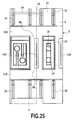
- the adjacent upstream sheet supporting portions 32 are connected to each other via a connection seat 37 at the lower portions thereof (see Figs. 22 , 23 , and 25 ). A clearance is formed between a sheet and the connection seat 37.
- the adjacent downstream sheet supporting portions 32 are connected to each other via a connection seat 37. A clearance is formed between the sheet 2 supported by the downstream sheet supporting portions 32 and the connection seat 37.
- the platen 9 is molded with a resin into a single component part. All of the sheet supporting portion 14, the upstream sheet supporting portion 32, the downstream sheet supporting portion 33, the first negative pressure chambers 22, and the ink receivers are aggregated into a single resin-molded component part that forms the platen 9. In this manner, it is possible to simplify the fabrication of the printing apparatus, and furthermore, to enhance the accuracy of relative positions among functional component parts.
- the sheet 2 stacked on a feed tray 5 is fed to the conveyance roller 7 by a feeder 40 shown in the first embodiment, and furthermore, is fed up to the platen 9 by the conveyance roller 7.
- the suction fan 19 is started during feeding the sheet 2 to generate a predetermined negative pressure at the duct 27 communicating with the suction holes 18 at the platen 9.
- the leading end 2a of the sheet 2 reaches the sheet supporting portion 14 beyond the ink discarding groove 31B adjacent to the upstream sheet supporting portions 32, and thereafter, is fed up to a position (i.e., a header position) slightly off a downstream end 14b. Since the negative pressure is generated inside of the suction recess 17 during this conveying operation, the leading end 2a of the sheet 2 is conveyed toward the supporting surface 13 while being sucked. Consequently, the floating of the leading end 2a of the sheet 2 can be suppressed.
- the printhead 3 performs reciprocal scanning based on image data, thereby starting the printing operation.
- an image is printed on the sheet 2, and furthermore, the ink is ejected up to a region outside (i.e., downstream) of the leading end of the sheet 2.
- the ink ejected to the region outside of the sheet 2 is discarded into the ink absorber 35 inside of the trailing end ink discarding groove 31 positioned downstream of the sheet supporting portion 14.
- the printing operation is continued by repeating the conveyance of the sheet 2 by the conveyance roller 7 and the discharge roller 10 and the reciprocal scanning of the printhead 3.
- the ink is ejected not only on the sheet 2 but also in regions outside of the right and left ends of the sheet 2 in a state shown in Figs. 22 and 24 .
- the platen 9 also has the right/left end ink discarding grooves 34 corresponding to the positions of the right and left ends of the sheet 2. The ink ejected to the outside of the right and left ends of the sheet 2 is discarded into the ink absorbers 35 in the right/left end ink discarding grooves 34 positioned outside of the right and left ends of the sheet 2.
- the printing operation is further continued, and then, the trailing end of the sheet 2 passes through a first conveyance roller pair (i.e., the conveyance roller 7 and a pinch roller 8), and thereafter, the sheet 2 is conveyed by a second conveyance roller pair (i.e., the discharge roller 10 and a pulley 11).
- a first conveyance roller pair i.e., the conveyance roller 7 and a pinch roller 8
- the sheet 2 is conveyed by a second conveyance roller pair (i.e., the discharge roller 10 and a pulley 11).
- the marginless printing is performed with respect to the trailing end 2b of the sheet 2.
- the ink is ejected not only onto the sheet 2 but also in a region outside (upstream) of the trailing end 2b of the sheet 2.
- the ink ejected to the region outside of the trailing end 2b of the sheet 2 is discarded into the ink absorber 35 (i.e., sponge) in the trailing end ink discarding groove 31B positioned upstream of the sheet supporting portion 14.
- the printing operation with respect to the trailing end 2b of the sheet 2 comes to an end in the state in which the sheet 2 is sucked to the sheet supporting surface 13.
- the sheet 2 is placed on the sheet supporting surface 13 of the sheet supporting portion 14 all the time from the beginning of the printing operation to the end thereof.
- a proper negative pressure is introduced into the suction recess 17, so that the printing operation can be performed in the state in which the sheet 2 is sucked to the sheet supporting surface 13 all the time.
- a sheet distance between the printhead 3 and the sheet 2 can be kept to be a predetermined proper distance, thereby accurately printing an image.
- a carriage 4 is provided with a sensor that detects the sheet end, the sheet end can be accurately placed on the tops of the ribs according to the detection by the sensor.
- a space region NA surrounded by the sheet 2, the sheet supporting portions 14, and the fore and trailing end ink discarding grooves 31A and 31B is defined in the contact state of the sheet 2 with the upstream sheet supporting portions 32 and the downstream sheet supporting portions 33.
- the space region NA communicates with the clearance defined by the connection seat 37 and the sheet 2, as described above.
- the clearance forms a communication channel that allows the space region NA to communicate with the outside.
- the space region NA includes the second suction hole 180, and therefore, a pressure in the space region NA is lower than an ambient pressure.
- air is supplied to the space region NA having a lower pressure (hereinafter referred to as a negative pressure portion) through the communication channel, as shown in Fig. 24 .
- a pressure in the negative pressure portion NA is increased (i.e., the negative pressure is reduced) by supplying the air to the negative pressure portion NA, thereby reducing a difference in pressure between the negative pressure portion NA and the surroundings of the end 2d of the sheet 2. Consequently, the speed of an air flow F3 at the surroundings of the end 2d of the sheet 2 is reduced. In this manner, it is possible to reduce the misalignment of a landing position by the printhead caused by the adverse influence of the air flow F3 so as to suppress the degradation of an image in the surroundings of the right end 2d of the sheet 2.
- Fig. 24 shows the right end 2d of the sheet 2, a similar effect can be produced as to the left end of the sheet 2.
- the upstream sheet supporting portions 32 and the downstream sheet supporting portions 33 are formed into a flat shape
- the following phenomenon emerges: namely, out of the air flows intruding into the second suction hole 180 positioned right under the sheet end 2d, the flow resistance of the air flow flowing upstream and downstream in the sheet conveyance direction (i.e., the Y direction) becomes larger than that of the air flow flowing in the sheet widthwise direction (i.e., the X direction).
- the rate of the air flow in the sheet widthwise direction markedly becomes larger than that of the air flow in the sheet conveyance direction (i.e., the Y direction) out of the air flows from the outside to the second suction hole 180.
- the rate of the air flow flowing into the second suction hole 180 depends on the air flow in the sheet widthwise direction.
- the air is sucked also through a suction hole (designated by reference numeral 181 in Fig. 24 ) formed at the suction recess 17 of the ink supporting portion 14 positioned outside of the sheet end 2d.
- a suction hole designated by reference numeral 181 in Fig. 24
- Most of the air outside of the sheet end 2d flows into the suction hole 181.
- a very slight quantity of the air flows into the suction hole 180 positioned right under the sheet end 2d from the outside of the sheet end 2d.
- the air strongly flows from the sheet end 2d to the second suction hole 180, and accordingly, the air rapidly flows from the center of the sheet toward the sheet end 2d around the end of the sheet.
- the ink ejected near the sheet end 2d flows by the force of the air flow, thereby causing the misalignment of the landing position, so as to raise a phenomenon that the image to be formed near the sheet end 2d is degraded.
- the width of the line becomes great, and therefore, the degradation of the image can be visually recognized with ease.
- the mist suction force at the second suction hole 180 formed at the right/left ink discarding groove 34 so as to suppress the degradation of the image around the end of the sheet.
- the air flow F2 from the sheet end 2d to the second suction hole 180 is weakened whereas the air flowing into the clearance defined between the sheet 2 and the sheet supporting surface 13 is increased, and therefore, the ink mist is liable to be transported to the reverse of the sheet. Consequently, the quantity of the ink mist adhering to the reverse of the sheet is increased.
- the communication channel is formed for supplying the air to the negative pressure portion NA in the present embodiment, thus achieving compatibility between the alleviation of the smear on the sheet 2 by the ink mist and the suppression of the degradation of the image around the sheet end.
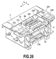
- FIG. 26 is a perspective view showing a first variation of the second embodiment.
- a downstream sheet supporting portion includes a wall 330 formed in the sheet widthwise direction (i.e., the X direction) outside (downstream) of the leading end ink discarding groove 31A.
- an upstream sheet supporting portion includes a wall 320 formed in the sheet widthwise direction (i.e., the X direction) outside (upstream) of the trailing end ink discarding groove 31B.
- Communication channels 260 and 261 which are through holes are formed inside of the walls 320 and 330 in the sheet conveyance direction (i.e., the Y direction), respectively.
- the communication channel 260 communicates with the trailing end ink discarding groove 31B.
- One opening 270 is formed at a position at which it communicates with the trailing end ink discarding groove 31B whereas the other opening 280 is formed at a surface (i.e., an outer surface) apart from the trailing end ink discarding groove 31B in the sheet conveyance direction.
- the communication channel 261 communicates with the leading end ink discarding groove 31A.
- One opening 271 is formed at a position at which it communicates with the leading end ink discarding groove 31A whereas the other opening 281 is formed at a surface (i.e., an outer surface) apart from the leading end ink discarding groove 31A in the sheet conveyance direction.
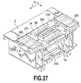
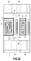
- Fig. 27 (a perspective view) and Fig. 28 (a plan view) are views showing a second variation of the second embodiment.
- the platen 9 includes communication channels 260 and 261 having openings 270 and 271, respectively, at positions at which a surface extending in the sheet conveyance direction (i.e., the Y direction) of the side face of the supporting portion 14 supporting the end of the sheet 2 crosses walls 320 and 330. Most of the air supplied to the negative pressure portion NA passes the communication channels 260 and 261.
- the communication channels 260 and 261 are arranged such that the first openings 270 and 271 are arranged at positions at which a surface 14F extending in the sheet conveyance direction of the side face of one of the supporting portions 14 on the same side as the end of the sheet 2 crosses the walls 320 and 330.
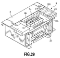
- Fig. 29 is a view showing a third variation of the second embodiment.
- a communication channel 260 is formed only on an upstream wall 320, that is, only on the wall 320 formed along the trailing end ink discarding groove 31B, but no communication channel is formed on a downstream wall. That is to say, no communication channel is formed on a wall 330 formed along the leading end ink discarding groove 31A.
- the communication channel 260 has an opening 270 formed at a position at which it faces the negative pressure portion NA. and the spur roller 11 (see Fig. 3 ).
- a communication channel may be formed only on the downstream wall 330 whereas no communication channel may be formed on the upstream wall 320.
- the communication channel is formed on either upstream or downstream wall at the platen, thus achieving compatibility between the alleviation of a smear on the sheet 2 and the suppression of the degradation of an image.
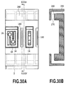
- Figs. 30A and 30B are views showing a fourth variation of the second embodiment.
- One opening of a communication channel 260 is formed at the reverse of the platen 9. Ink mist caused by printing may not be completely recovered only due to the suction through the second suction hole 180, and consequently, it may float inside of a space defined at the upper portion of the platen 9 inside of the printing apparatus. It is desirable that air supplied to the negative pressure portion NA through the communication channel 260 should not be contaminated by the mist.
- one opening 280 of the communication channel 260 is formed at the reverse of the platen 9 in Figs. 30A and 30B .
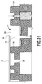
- Fig. 31 is a view showing a fifth variation of the second embodiment.
- This variation is configured in such a manner as to stop the suction through the suction hole 18 at the sheet supporting portion 14 that is not covered with the sheet in a case where the sheet 2 having a certain width is sucked and held.
- the suction through the suction holes 18 formed at the plurality of different positions in the sheet widthwise direction is individually controlled according to the width of the sheet that is used.
- a stopper of the suction at the sheet supporting portion 14 is exemplified by a valve 250 for switching communication and cutoff of the suction hole 18 at the lower portion of the sheet supporting portion 14. As for the sheet supporting portion 14 disposed outside of the sheet, the valve 250 is moved upward, as shown in Fig.
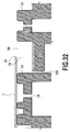
- Fig. 32 is a view showing a sixth variation of the second embodiment.
- the second suction hole 180 is formed not right under the sheet 2 but along the side wall of the sheet supporting portion 14 that sucks and holds the sheet 2. Consequently, the ink discarded into the right/left ink discarding groove 34 adheres to the second suction hole 180, and then, is solidified, thus suppressing the reduction of the recovery quantity of the ink mist. Furthermore, in comparison with a case where the second suction hole 180 is formed right under the end of the sheet 2, more air is supplied to the second suction hole 180 along the side wall of the sheet supporting portion 14 from the surroundings of the end of the sheet 2.
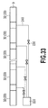
- Fig. 33 is a view showing a seventh variation of the second embodiment.
- a plurality of communication channels defined between the upstream sheet supporting portions 32 and between the downstream sheet supporting portions 33 and a common pressurizer 220 are connected via a plurality of channels 240, and furthermore, a valve 230 is disposed on each of the channels 240.
- the opening/closing or the opening degrees of the plurality of valves 230 are individually controlled.
- the plurality of valves 230 are controlled according to the width of the sheet that is used.
- the pressurizer 220 and the plurality of valves 230 configure an air supplier at an active individual pressurizing mechanism.
- Fig. 34 is a view showing an eighth variation of the second embodiment.
- an active individual pressurizing mechanism is added to the variations shown in Figs. 26 to 30B .
- the communication channels formed on the wall 320 and a pressurizer 220 are connected to each other via a plurality of channels 240, and furthermore, a plurality of valves 230 are disposed on the channels 240, respectively, thereby adjusting the flow rate of air to be supplied under the individual control by the valve 230.
- the pressurizer and the supplier for individually pressurizing and supplying the air to each of the communication channels disposed at the plurality of different positions in the sheet widthwise direction.
- the fourside marginless printing can be performed with respect to a cut sheet. It is possible to securely perform the marginless printing, and furthermore, to suppress any smear on the reverse of the sheet with the ink mist generated during the ejection of the ink to the outside of the sheet end.
- a platen 9 substantially similar to that in the first embodiment.
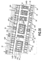
- Fig. 35 is an enlarged perspective view partly showing the platen shown in Fig. 1 , as viewed from above.
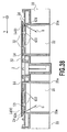
- Fig. 36 is a vertical side view showing the platen shown in Fig. 35 and its surroundings.
- Figs. 35 and 36 show a channel in which ink mist generated during printing around a sheet leading end.
- the platen 9 is interposed between a first conveyance roller pair including a conveyance roller 7 and a pinch roller 8 and a second conveyance roller pair including a discharge roller 10 and a pulley 11.
- the platen 9 supports a sheet 2 conveyed by the first and second conveyance roller pairs at a surface (i.e., a reverse) opposite to a print surface.
- the platen 9 has sheet supporting portions (i.e., supporting portions) 14 capable of supporting the reverse of the sheet while suppressing floating or flexure of the sheet 2.
- the plurality of sheet supporting portions 14 are formed in a longitudinal direction (i.e., an X direction) of the platen 9.
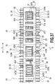
- Fig. 37 is an enlarged plan view partly showing the platen 9 shown in Fig. 36 .
- Each of the sheet supporting portions 14 is formed into a rectangular frame with a ribbed projection.
- a suction recess (i.e., a suction unit) 17 is formed at the upper portion of the sheet supporting portion 14 in such a manner as to be lower by one step than the sheet supporting surface 13.
- a suction hole 18 is formed at the bottom of the suction recess 17 in such a manner as to penetrate the platen 9.
- the suction hole 18 communicates with a negative pressure generator 19 such as a fan.
- Upstream sheet supporting portions 32 for supporting the reverse of the sheet 2 conveyed by the conveyance roller 7 are formed further upstream of a trailing end ink discarding groove 31B, described later, formed on the platen 9. Additionally, downstream sheet supporting portions 33 for supporting the reverse of the sheet 2 conveyed by the discharge roller 10 are formed further downstream of a leading end ink discarding groove 31A, described later, formed on the platen 9.
- Each of the upstream sheet supporting portions 32 and the downstream sheet supporting portions 33 includes a ribbed projection extending in a sheet conveyance direction (i.e., a Y direction).
- the plurality of upstream sheet supporting portions 32 and the plurality of downstream sheet supporting portions 33 are arranged in the X direction at a constant interval, as shown in Fig. 37 .
- each of the upstream sheet supporting portions 32 and the downstream sheet supporting portions 33 is formed in the same height as that of a sheet supporting surface (i.e., a contact portion) 13 of the sheet supporting portion 14.
- the upstream sheet supporting portion 32 and the downstream sheet supporting portion 33 fulfill the function of preventing the sheet 2 from falling or being involved in a case where the fore or trailing end of the sheet 2 passes the sheet supporting portion 14 and the rollers.
- ink is ejected to the outside of the sheet 2 immediately before a printing operation, that is, so-called preliminary ejection is performed in order to stabilize ink ejection performance of the printhead 3.
- preliminary ejection is performed in order to stabilize ink ejection performance of the printhead 3.
- the ink receivers in this embodiment there are provided a leading end ink discarding groove 31A for receiving ink ejected to the outside of the leading end 2a of the sheet and a trailing end ink discarding groove 31B for receiving ink ejected to the outside of the trailing end 2b of the sheet.
- the ink receivers include right/left end ink discarding grooves 34 that receive ink ejected to the outside of the right and left ends (i.e., sheet side ends) of the sheet 2 in the sheet widthwise direction.
- Fig. 36 shows the cross sections of the leading end ink discarding groove (i.e., a first ink receiver) 31A and the trailing end ink discarding groove (i.e., a second ink receiver) 31B at the platen 9.
- the leading end ink discarding groove 31A is elongated in the X direction adjacently downstream of the sheet supporting portion 14 whereas the trailing end ink discarding groove 31B is elongated in the X direction adjacently upstream of the sheet supporting portion 14.
- the platen 9 has right/left end ink discarding grooves (i.e., a third ink receiver) 34 according to each width of the sheet in such a manner as to receive the ink ejected to the outside of the right and left ends of the sheet 2 (see Fig. 35 ).
- the sheets 2 that can be subjected to marginless printing have mainly standard sizes such as an L size, a 2L size, a postcard size, an A4 size, a letter size, an A3 size, a legal size, and an A2 size.
- the plurality of ink discarding grooves 34 are formed at positions corresponding to the right and left ends of the sheet 2 according to the sizes of sheets.
- the leading end ink discarding groove 31A, the trailing end ink discarding groove 31B, and the right/left end ink discarding grooves 34 are formed in a grid manner at the surface of the platen 9 (see Fig. 35 ).
- an ink absorber 35 is disposed at each of the ink discarding grooves 31A, 31B, and 34, as shown in Figs. 37 and 39 . It is preferable that the ink absorber 35 should be a spongy single sheet made of expanded urethane.
- the upper surface of the ink absorber 35 is locked by a plurality of lock claws 38 (see Fig. 37 ), so that the ink absorber 35 can be inhibited from being detached from the platen 9.
- the plurality of spaces 22 defined by the partition walls 20a and the outer peripheral walls 20 serve as negative pressure chambers, to which a negative pressure is applied by a negative pressure generator 19.
- the negative pressure chambers 22 correspond to the suction recesses 17 formed at the sheet supporting portions 14, respectively.
- the negative pressure generator 19 applies a negative pressure to the negative pressure chamber 22, so that air is sucked through the suction holes 18 formed at the suction recess 17, thus sucking the sheet 2 to the sheet supporting surface 13 of the sheet supporting portion 14.
- first and second slits 423 and 424 for sucking and recovering ink mist generated at the time of the ejection of the ink into an ink receiving groove are formed on the side walls of the sheet supporting portion 14 at the platen 9.
- Figs. 35 and 37 show positions where the first and second slits 423 and 424 are formed.
- the first slit 423 is formed on a downstream side wall 140A substantially parallel to the sheet widthwise direction (i.e., the X direction) crossing the sheet conveyance direction (i.e., the Y direction) at each of the sheet supporting portions 14.
- the second slit 424 is formed on a side wall 140D substantially parallel to the sheet conveyance direction at each of the sheet supporting portions 14.
- the first slit 423 and the second slit 424 communicate with the negative pressure chamber 22. Therefore, the drive of the negative pressure generator 19 causes air to be sucked through not only the suction holes 18 but also the slits 423 and 424.
- the ink ejected to the outside (i.e., downstream) of the leading end of the sheet 2 is landed on the ink absorber 35 positioned in the leading end ink discarding groove 31A.
- atomized fine ink droplets i.e., ink mist
- the ink mist is sucked toward the suction recess 17 by the negative pressure through the suction hole 18, and then, passes a fine clearance defined between the sheet supporting portion 14 and the sheet 2.
- a part of the mist is brought into contact with and adheres to the reverse of the sheet 2, which may be smeared with the mist.
- the first slit 423 is formed on the downstream side wall 140A of the sheet supporting portion 14 in the present embodiment, the ink mist is sucked through the first slit 423, as indicated by an arrow F in Fig. 36 , before being sucked to the suction hole 18.
- the marginless printing it is possible to remarkably reduce a contact of the ink mist on the reverse of the sheet 2 so as to markedly alleviate a smear on the reverse of the sheet 2 with the ink mist.
- the second slit 423 is formed on the downstream side wall 140A of the sheet supporting portion 14 in the present embodiment.
- a similar slit may be formed on the upstream side wall 140B of the sheet supporting portion 14, thus alleviating the adhesion of ink mist onto the trailing end 2b of the sheet 2.
- Fig. 37 is an enlarged plan view partly showing the platen 9, and shows the positional relationship between the sheet supporting portion 14 at the platen 9 and the sheets 2 having different sizes.
- Fig. 38 is a vertical front view showing the platen 9, and shows a channel onto which ink mist is sucked in a case where the right and left ends 2c and 2d of the sheet 2 are printed.
- the arrangement of the sheet supporting portion 14 in the sheet widthwise direction (i.e., the X direction) and the position of the ink discarding groove are determined according to the size of the sheet which can be subjected to the marginless printing (e.g., an L size, a KG size, a 2L size, an A4 size, a letter size, or an A3 size) and a print position reference.
- the reference of the print position is set at the center of the width of a sheet: namely, a so-called center reference sheet supply is adopted.
- Fig. 37 shows the positional relationship between the end of each of an A4-size sheet 2 and an A3-size sheet 2 and each of the sheet supporting portions 14 at the platen 9.
- Fig. 37 shows the positional relationship between the end of each of an A4-size sheet 2 and an A3-size sheet 2 and each of the sheet supporting portions 14 at the platen 9.
- reference character P0 designates the print position reference (i.e., a center reference) of the platen 9 and the sheet 2; P1, the position of the end of the A4-size sheet 2; and P2, the position of the end of the A3-size sheet 2.
- a center reference i.e., a center reference
- P1 the print position reference
- P2 the position of the end of the A3-size sheet 2.
- the center reference not the center reference but a one-side reference may be adopted such that all sheets having various sheet widths are aligned at either one of right and left reference positions.
- the first slit 423 is formed on the side wall nearer the left and right ends 2c and 2d of the sheet 2.
- the second slit 424 is formed on the right side wall 140D at the sheet supporting portion 14 positioned rightward of the center reference P0, as shown in Figs. 37 and 38 .
- the second slit 424 is formed on the left side wall 140C at the sheet supporting portion 14 positioned leftward of the center reference P0 (see Fig. 38 ).
- the second slit 424 communicates with the negative pressure chamber 22 formed in such a manner as to correspond to the sheet supporting portion 14. Therefore, air outward of the sheet supporting portion 14 can be sucked into the negative pressure chamber 22 under the negative pressure applied to the negative pressure chamber 22 by the negative pressure generator 19.
- the ink mist generated during the marginless printing at the left and right ends 2c and 2d of the sheet 2 is speedily sucked through the second slit 424 positioned near the left and right ends 2c and 2d of the sheet 2, as indicated by an arrow G in Fig 38 , to be sent to the negative pressure chamber 22.
- the second slit 424 is formed on the side wall near the left and right ends 2c and 2d of the sheet 2 out of the left and right side walls 140C and 140D of the sheet supporting portion 14, another slit may be formed on the other side wall.
- a slit is simply required to be formed on a side wall remoter than at least the reference out of the right and left side walls of the sheet supporting portion 14.
- Fig. 39 is an enlarged vertical side view showing the sheet supporting portion 14, and shows the configuration of the second slit 424 formed at the sheet support 14.
- the second slit 424 formed on the left side wall 140C of the sheet supporting portion 14 is described with reference to Fig. 39 .
- Both of the second list 424 formed on the right side wall 140D and the first slit 423 formed on the downstream side wall 140A have the same configuration. Therefore, duplicated explanation on the slit 424 will be omitted.
- a substantially horizontal step 141 is formed on the left side wall 140C of the sheet supporting portion 14, and furthermore, a side face 142 rising up from the step 141 is formed.
- the second slit 424 is formed between the step 141 and the side face 142 in the sheet conveyance direction (i.e., the Y direction). Both of the side wall 140C and the side face 142 of the sheet supporting portion 14 are formed in such a manner as to extend in a substantially vertical direction.
- the second slit 424 is formed by forming the step 141 on the side wall 140C extending in the substantially vertical direction.
- a side wall may be inclined, and then, a slit may be formed on the inclined side wall.
- the inclination increases a distance in the sheet widthwise direction, and furthermore, an interval between adjacent sheet supporting portions 14 is required to be increased in a case where a capacity similar to that in the present embodiment is provided for an ink receiving groove, so that a sheet is liable to fall between the adjacent sheet supporting portions.
- a distance between a printhead and a sheet may be unfavorably varied, thereby inducing misalignment of the landing position of ink ejected by the printhead, so as to degrade an image.
- the sheet is brought into contact with an ink absorber 35 according to how much the sheet falls, thereby raising a fear of a smear on the sheet.
- the ink absorber 35 is required to be formed in a non-uniform thickness according to the inclination of the side wall on which the slit is formed, thereby making it difficult to fabricate the ink absorber.
- the side wall 140C is formed in the substantially vertical direction in the present embodiment, the interval between the adjacent sheet supporting portions 14 can be suppressed to a required minimum interval. Consequently, it is possible to avoid the sheet from falling in the ink discarding groove or waste ink from adhering to the reverse of the sheet. Furthermore, the ink absorber 35 is simply required to be formed in a uniform thickness, thereby facilitating fabrication.
- Fig. 40 is an enlarged vertical side view partly showing the platen 9 shown in Fig. 36 , and shows the positional relationship between the first slit 423 and the ink absorber 35.
- the opening of the first slit 423 is formed at the downstream ink receiving groove 31A at a position higher by a clearance Z1 than the ink absorber 35 in the vertical direction (i.e., near the printhead 3). With this positional relationship, even in a case where the ink absorber 35 is filled with waste ink, it is possible to avoid the waste ink from flowing into the first slit 423 via the side wall 140A adjoining the leading end ink discarding groove 31A or the step 141.
- the positional relationship between the second slit 424 formed on each of the left and right side walls 140C and 140D and the ink absorber 35 is determined in the same manner as the positional relationship between the ink absorber 35 and the opening of the first slit 423 in the vertical direction.
- the ink absorber 35 can be incorporated in the ink discarding groove, the ink absorber 35 can be incorporated while visually comparing the positions of the end of the ink absorber 35 and the step 141 with each other. As a consequence, the step 141 is effective in preventing erroneous incorporation.
- the platen 9 is molded with a resin into a single component part. All of the sheet supporting portion 14, the upstream sheet supporting portion 32, the downstream sheet supporting portion 33, the plurality of the negative pressure chambers 22, the plurality of ink receivers (i.e., the first to third ink receivers) are aggregated into a single resin-molded component part that constitutes the platen 9. In this manner, it is possible to simplify the fabrication of the printing apparatus, and furthermore, to enhance the accuracy of relative positions among functional component parts.
- the step 141 is formed on the side wall 140D formed at the sheet supporting portion 14 in the vertical direction, and furthermore, the side face 142 rising from the step 141 in the substantially vertical direction is formed to define the slit for absorbing the ink between the step 141 and the side face 142.
- Fig. 41 shows cases where the first slit 423 is formed on the upstream side wall 140A whereas the second slit 424 is formed on the right side wall 140D
- the first and second slits may be formed on the other side walls 140B and 140C.
- the openings of the slits 426 are formed at a position higher than the ink absorber 35 (i.e., a position near the printhead 3) in order to avoid the waste ink from flowing into the slit 425 (see Fig. 42 ).
- the other configuration is identical to that in the third embodiment.
- the formation of the slit on any side walls formed on the sheet supporting portion 14 is effective in sucking the ink mist.
- the upstream side wall is upward inclined from downstream to upstream, thereby forming an inclined face.
- the inclined face may function as a guide face for smoothly moving the leading end of the sheet toward the sheet supporting surface.
- the slit possibly prevents the smooth movement of the sheet.
- the ink mist may adhere onto the upstream side wall during the suction into the slit, and accordingly, the reverse of the sheet to be guided on the side wall may be possibly smeared with the ink. For the above-described reasons, it may be undesirable to form a slit on the upstream side wall.
- the fourside marginless printing can be performed with respect to a cut sheet.
Landscapes
- Handling Of Sheets (AREA)
- Ink Jet (AREA)
Applications Claiming Priority (3)
| Application Number | Priority Date | Filing Date | Title |
|---|---|---|---|
| JP2015107991A JP6532297B2 (ja) | 2015-05-27 | 2015-05-27 | プリント装置 |
| JP2015107999A JP6532298B2 (ja) | 2015-05-27 | 2015-05-27 | プリント装置 |
| JP2015107994A JP6478812B2 (ja) | 2015-05-27 | 2015-05-27 | プリント装置 |
Publications (2)
| Publication Number | Publication Date |
|---|---|
| EP3098083A1 true EP3098083A1 (de) | 2016-11-30 |
| EP3098083B1 EP3098083B1 (de) | 2021-08-25 |
Family
ID=55910073
Family Applications (1)
| Application Number | Title | Priority Date | Filing Date |
|---|---|---|---|
| EP16000985.8A Active EP3098083B1 (de) | 2015-05-27 | 2016-05-02 | Druckvorrichtung und -platte |
Country Status (4)
| Country | Link |
|---|---|
| US (2) | US10071572B2 (de) |
| EP (1) | EP3098083B1 (de) |
| KR (1) | KR102036954B1 (de) |
| CN (1) | CN106183413B (de) |
Cited By (2)
| Publication number | Priority date | Publication date | Assignee | Title |
|---|---|---|---|---|
| CN109605943A (zh) * | 2018-11-12 | 2019-04-12 | 杭州御澜科技有限公司 | 一种写真机 |
| CN116638873A (zh) * | 2022-02-24 | 2023-08-25 | 佳能株式会社 | 打印设备 |
Families Citing this family (8)
| Publication number | Priority date | Publication date | Assignee | Title |
|---|---|---|---|---|
| JP6525836B2 (ja) * | 2015-09-24 | 2019-06-05 | キヤノン株式会社 | プリント装置 |
| JP6775941B2 (ja) | 2015-12-08 | 2020-10-28 | キヤノン株式会社 | 記録装置 |
| US10105971B1 (en) | 2017-09-06 | 2018-10-23 | Hewlett-Packard Development Company, L.P. | Platen rib protector |
| JP7171306B2 (ja) | 2018-08-10 | 2022-11-15 | キヤノン株式会社 | 液体吐出装置 |
| JP2021037701A (ja) * | 2019-09-03 | 2021-03-11 | キヤノン株式会社 | インクジェット記録装置 |
| JP7749359B2 (ja) | 2021-06-29 | 2025-10-06 | キヤノン株式会社 | 記録装置 |
| JP2024010888A (ja) | 2022-07-13 | 2024-01-25 | キヤノン株式会社 | 記録装置 |
| ES3059718A1 (es) * | 2024-09-18 | 2026-03-23 | Electronics For Imaging Inc | Sistemas para la gestión del flujo de aire en impresoras de inyección de tinta |
Citations (2)
| Publication number | Priority date | Publication date | Assignee | Title |
|---|---|---|---|---|
| US20050062794A1 (en) * | 2002-06-11 | 2005-03-24 | Seiko Epson Corporation | Waste liquid treating device and liquid ejecting apparatus incorporating the same |
| JP2006021475A (ja) | 2004-07-09 | 2006-01-26 | Seiko Epson Corp | プラテン及び該プラテンを備えた記録装置と液体噴射装置 |
Family Cites Families (45)
| Publication number | Priority date | Publication date | Assignee | Title |
|---|---|---|---|---|
| US5200767A (en) | 1989-02-14 | 1993-04-06 | Canon Kabushiki Kaisha | Recording apparatus having timing belt driving mechanism for driving recording head |
| EP0479270B1 (de) | 1990-10-03 | 1996-05-22 | Canon Kabushiki Kaisha | Aufzeichnungsgerät |
| JP3372701B2 (ja) | 1994-05-30 | 2003-02-04 | キヤノン株式会社 | インクジェット記録装置 |
| JPH11240146A (ja) | 1997-12-26 | 1999-09-07 | Canon Inc | 記録装置 |
| US6299293B1 (en) | 1998-12-03 | 2001-10-09 | Canon Kabushiki Kaisha | Substrate for liquid discharge head, liquid discharge head and liquid discharge apparatus |
| US6435655B1 (en) | 1999-12-14 | 2002-08-20 | Canon Kabushiki Kaisha | Color ink jet recording method/apparatus |
| JP2001219548A (ja) | 2000-02-07 | 2001-08-14 | Canon Inc | インクジェット記録装置 |
| US6543892B2 (en) | 2000-03-27 | 2003-04-08 | Canon Kabushiki Kaisha | Printing apparatus |
| JP2002166561A (ja) | 2000-11-30 | 2002-06-11 | Canon Inc | 記録装置の電源制御方法 |
| CN1193892C (zh) * | 2001-10-17 | 2005-03-23 | 精工爱普生株式会社 | 被固定材料输送装置、排出装置、排出方法和固液装置 |
| US6802591B2 (en) * | 2002-02-12 | 2004-10-12 | Seiko Epson Corporation | Liquid jet apparatus |
| JP3978725B2 (ja) * | 2002-04-18 | 2007-09-19 | セイコーエプソン株式会社 | 液体噴射装置 |
| JP2003326787A (ja) | 2002-05-09 | 2003-11-19 | Canon Inc | 記録装置 |
| JP4078114B2 (ja) * | 2002-05-14 | 2008-04-23 | キヤノン株式会社 | インクジェット画像形成装置 |
| JP4208604B2 (ja) | 2003-02-26 | 2009-01-14 | キヤノン株式会社 | インクジェット記録装置およびインクジェット記録装置における記録制御方法 |
| JP4336976B2 (ja) | 2003-08-28 | 2009-09-30 | セイコーエプソン株式会社 | 記録装置 |
| JP4622405B2 (ja) * | 2003-09-18 | 2011-02-02 | セイコーエプソン株式会社 | 印刷方法、印刷装置、およびプログラム |
| WO2006054796A1 (en) | 2004-11-19 | 2006-05-26 | Canon Kabushiki Kaisha | Ink jet printing apparatus, method of manufacturing ink absorber, and ink absorber |
| JP4632028B2 (ja) * | 2004-11-24 | 2011-02-16 | セイコーエプソン株式会社 | 記録装置 |
| JP2007083452A (ja) | 2005-09-20 | 2007-04-05 | Seiko Epson Corp | 記録装置および液体噴射装置 |
| JP4687885B2 (ja) | 2005-09-21 | 2011-05-25 | セイコーエプソン株式会社 | 液体噴射装置 |
| JP2007118502A (ja) * | 2005-10-31 | 2007-05-17 | Seiko Epson Corp | 液体噴射装置及び記録装置 |
| JP2007144825A (ja) | 2005-11-29 | 2007-06-14 | Canon Inc | インクジェット記録装置 |
| JP2007152762A (ja) * | 2005-12-06 | 2007-06-21 | Fujifilm Corp | 画像記録装置 |
| US7887179B2 (en) * | 2006-06-15 | 2011-02-15 | Canon Kabushiki Kaisha | Inkjet recording apparatus |
| JP5231766B2 (ja) | 2007-07-20 | 2013-07-10 | キヤノン株式会社 | インクジェット記録装置 |
| US20090021556A1 (en) * | 2007-07-20 | 2009-01-22 | Xiangdong Zhao | Imaging device |
| JP2009039982A (ja) | 2007-08-10 | 2009-02-26 | Canon Inc | インクジェット記録装置 |
| JP5424624B2 (ja) | 2008-12-02 | 2014-02-26 | キヤノン株式会社 | 記録装置 |
| JP5361436B2 (ja) | 2009-02-20 | 2013-12-04 | キヤノン株式会社 | プリンタ |
| JP5472597B2 (ja) * | 2009-08-28 | 2014-04-16 | セイコーエプソン株式会社 | 被噴射材支持部材、該被噴射材支持部材を備えた液体噴射装置 |
| JP5560733B2 (ja) * | 2010-01-25 | 2014-07-30 | セイコーエプソン株式会社 | 印刷装置 |
| JP2012040759A (ja) * | 2010-08-19 | 2012-03-01 | Seiko Epson Corp | 記録装置 |
| JP5737886B2 (ja) | 2010-08-31 | 2015-06-17 | キヤノン株式会社 | インクジェット記録装置 |
| JP5750929B2 (ja) | 2011-02-16 | 2015-07-22 | セイコーエプソン株式会社 | 液体噴射装置 |
| JP6041526B2 (ja) | 2012-05-08 | 2016-12-07 | キヤノン株式会社 | インクジェット記録装置 |
| TW201404616A (zh) | 2012-07-20 | 2014-02-01 | 鴻海精密工業股份有限公司 | 收集裝置 |
| JP6150653B2 (ja) | 2013-07-30 | 2017-06-21 | キヤノン株式会社 | インクジェットプリント装置 |
| JP6444097B2 (ja) | 2013-09-24 | 2018-12-26 | キヤノン株式会社 | 記録装置 |
| JP6388376B2 (ja) | 2014-06-04 | 2018-09-12 | キヤノン株式会社 | 液体吐出装置 |
| US20160288505A1 (en) * | 2015-04-02 | 2016-10-06 | Canon Kabushiki Kaisha | Printing apparatus |
| JP6584146B2 (ja) | 2015-05-27 | 2019-10-02 | キヤノン株式会社 | プリント装置 |
| US10183505B2 (en) | 2015-05-27 | 2019-01-22 | Canon Kabushiki Kaisha | Printing apparatus and platen |
| US10011124B2 (en) | 2015-05-27 | 2018-07-03 | Canon Kabushiki Kaisha | Performing marginless printing based on image data |
| JP6622632B2 (ja) * | 2016-03-11 | 2019-12-18 | キヤノン株式会社 | 画像記録装置 |
-
2016
- 2016-05-02 EP EP16000985.8A patent/EP3098083B1/de active Active
- 2016-05-19 KR KR1020160061212A patent/KR102036954B1/ko active Active
- 2016-05-20 US US15/160,532 patent/US10071572B2/en active Active
- 2016-05-27 CN CN201610364521.4A patent/CN106183413B/zh active Active
-
2018
- 2018-08-07 US US16/057,011 patent/US10549554B2/en active Active
Patent Citations (2)
| Publication number | Priority date | Publication date | Assignee | Title |
|---|---|---|---|---|
| US20050062794A1 (en) * | 2002-06-11 | 2005-03-24 | Seiko Epson Corporation | Waste liquid treating device and liquid ejecting apparatus incorporating the same |
| JP2006021475A (ja) | 2004-07-09 | 2006-01-26 | Seiko Epson Corp | プラテン及び該プラテンを備えた記録装置と液体噴射装置 |
Cited By (2)
| Publication number | Priority date | Publication date | Assignee | Title |
|---|---|---|---|---|
| CN109605943A (zh) * | 2018-11-12 | 2019-04-12 | 杭州御澜科技有限公司 | 一种写真机 |
| CN116638873A (zh) * | 2022-02-24 | 2023-08-25 | 佳能株式会社 | 打印设备 |
Also Published As
| Publication number | Publication date |
|---|---|
| EP3098083B1 (de) | 2021-08-25 |
| US20180339530A1 (en) | 2018-11-29 |
| US10549554B2 (en) | 2020-02-04 |
| KR102036954B1 (ko) | 2019-10-25 |
| US20160347092A1 (en) | 2016-12-01 |
| KR20160140395A (ko) | 2016-12-07 |
| US10071572B2 (en) | 2018-09-11 |
| CN106183413B (zh) | 2018-10-16 |
| CN106183413A (zh) | 2016-12-07 |
Similar Documents
| Publication | Publication Date | Title |
|---|---|---|
| US10549554B2 (en) | Printing apparatus and platen | |
| US10183505B2 (en) | Printing apparatus and platen | |
| US9802426B2 (en) | Printing apparatus and platen | |
| JP4500227B2 (ja) | 用紙搬送機構 | |
| US10232644B2 (en) | Printing apparatus and platen | |
| JP6478812B2 (ja) | プリント装置 | |
| US20120050398A1 (en) | Inkjet printing apparatus | |
| JP3928707B2 (ja) | 記録媒体の搬送装置及びインクジェット式記録装置 | |
| US20170259571A1 (en) | Image printing apparatus | |
| US10011124B2 (en) | Performing marginless printing based on image data | |
| JP2004268416A (ja) | 記録媒体搬送装置及び記録装置 | |
| US10124608B2 (en) | Image printing apparatus | |
| JP2009291982A (ja) | インクジェット記録装置 | |
| JP2016221720A (ja) | プリント装置およびプラテン | |
| JP2001219553A (ja) | インクジェット式記録装置 | |
| EP1419890B1 (de) | Vakuumschreibträgeranordnung fur Flüssigkeitsausstossgerät | |
| JP6532298B2 (ja) | プリント装置 | |
| JP6391736B2 (ja) | プリント装置 | |
| JP4066321B2 (ja) | 記録媒体の搬送装置及びインクジェット式記録装置 | |
| JP2016196110A (ja) | プリント装置 | |
| JP6602052B2 (ja) | プリント装置 | |
| JP5614561B2 (ja) | インクジェット式記録装置 | |
| JP2005111995A (ja) | インクジェット式記録装置 | |
| JP2018144355A (ja) | インクジェット記録装置およびインクジェット記録方法 | |
| JP2006306113A (ja) | インクジェット式記録装置のプラテン |
Legal Events
| Date | Code | Title | Description |
|---|---|---|---|
| PUAI | Public reference made under article 153(3) epc to a published international application that has entered the european phase |
Free format text: ORIGINAL CODE: 0009012 |
|
| AK | Designated contracting states |
Kind code of ref document: A1 Designated state(s): AL AT BE BG CH CY CZ DE DK EE ES FI FR GB GR HR HU IE IS IT LI LT LU LV MC MK MT NL NO PL PT RO RS SE SI SK SM TR |
|
| AX | Request for extension of the european patent |
Extension state: BA ME |
|
| STAA | Information on the status of an ep patent application or granted ep patent |
Free format text: STATUS: REQUEST FOR EXAMINATION WAS MADE |
|
| 17P | Request for examination filed |
Effective date: 20170530 |
|
| RBV | Designated contracting states (corrected) |
Designated state(s): AL AT BE BG CH CY CZ DE DK EE ES FI FR GB GR HR HU IE IS IT LI LT LU LV MC MK MT NL NO PL PT RO RS SE SI SK SM TR |
|
| STAA | Information on the status of an ep patent application or granted ep patent |
Free format text: STATUS: EXAMINATION IS IN PROGRESS |
|
| 17Q | First examination report despatched |
Effective date: 20190402 |
|
| GRAP | Despatch of communication of intention to grant a patent |
Free format text: ORIGINAL CODE: EPIDOSNIGR1 |
|
| STAA | Information on the status of an ep patent application or granted ep patent |
Free format text: STATUS: GRANT OF PATENT IS INTENDED |
|
| INTG | Intention to grant announced |
Effective date: 20210316 |
|
| GRAS | Grant fee paid |
Free format text: ORIGINAL CODE: EPIDOSNIGR3 |
|
| GRAA | (expected) grant |
Free format text: ORIGINAL CODE: 0009210 |
|
| STAA | Information on the status of an ep patent application or granted ep patent |
Free format text: STATUS: THE PATENT HAS BEEN GRANTED |
|
| AK | Designated contracting states |
Kind code of ref document: B1 Designated state(s): AL AT BE BG CH CY CZ DE DK EE ES FI FR GB GR HR HU IE IS IT LI LT LU LV MC MK MT NL NO PL PT RO RS SE SI SK SM TR |
|
| RAP3 | Party data changed (applicant data changed or rights of an application transferred) |
Owner name: CANON KABUSHIKI KAISHA |
|
| REG | Reference to a national code |
Ref country code: CH Ref legal event code: EP |
|
| REG | Reference to a national code |
Ref country code: DE Ref legal event code: R096 Ref document number: 602016062598 Country of ref document: DE |
|
| REG | Reference to a national code |
Ref country code: IE Ref legal event code: FG4D Ref country code: AT Ref legal event code: REF Ref document number: 1423400 Country of ref document: AT Kind code of ref document: T Effective date: 20210915 |
|
| REG | Reference to a national code |
Ref country code: LT Ref legal event code: MG9D |
|
| REG | Reference to a national code |
Ref country code: NL Ref legal event code: MP Effective date: 20210825 |
|
| REG | Reference to a national code |
Ref country code: AT Ref legal event code: MK05 Ref document number: 1423400 Country of ref document: AT Kind code of ref document: T Effective date: 20210825 |
|
| PG25 | Lapsed in a contracting state [announced via postgrant information from national office to epo] |
Ref country code: HR Free format text: LAPSE BECAUSE OF FAILURE TO SUBMIT A TRANSLATION OF THE DESCRIPTION OR TO PAY THE FEE WITHIN THE PRESCRIBED TIME-LIMIT Effective date: 20210825 Ref country code: SE Free format text: LAPSE BECAUSE OF FAILURE TO SUBMIT A TRANSLATION OF THE DESCRIPTION OR TO PAY THE FEE WITHIN THE PRESCRIBED TIME-LIMIT Effective date: 20210825 Ref country code: RS Free format text: LAPSE BECAUSE OF FAILURE TO SUBMIT A TRANSLATION OF THE DESCRIPTION OR TO PAY THE FEE WITHIN THE PRESCRIBED TIME-LIMIT Effective date: 20210825 Ref country code: ES Free format text: LAPSE BECAUSE OF FAILURE TO SUBMIT A TRANSLATION OF THE DESCRIPTION OR TO PAY THE FEE WITHIN THE PRESCRIBED TIME-LIMIT Effective date: 20210825 Ref country code: FI Free format text: LAPSE BECAUSE OF FAILURE TO SUBMIT A TRANSLATION OF THE DESCRIPTION OR TO PAY THE FEE WITHIN THE PRESCRIBED TIME-LIMIT Effective date: 20210825 Ref country code: PT Free format text: LAPSE BECAUSE OF FAILURE TO SUBMIT A TRANSLATION OF THE DESCRIPTION OR TO PAY THE FEE WITHIN THE PRESCRIBED TIME-LIMIT Effective date: 20211227 Ref country code: NO Free format text: LAPSE BECAUSE OF FAILURE TO SUBMIT A TRANSLATION OF THE DESCRIPTION OR TO PAY THE FEE WITHIN THE PRESCRIBED TIME-LIMIT Effective date: 20211125 Ref country code: AT Free format text: LAPSE BECAUSE OF FAILURE TO SUBMIT A TRANSLATION OF THE DESCRIPTION OR TO PAY THE FEE WITHIN THE PRESCRIBED TIME-LIMIT Effective date: 20210825 Ref country code: BG Free format text: LAPSE BECAUSE OF FAILURE TO SUBMIT A TRANSLATION OF THE DESCRIPTION OR TO PAY THE FEE WITHIN THE PRESCRIBED TIME-LIMIT Effective date: 20211125 Ref country code: LT Free format text: LAPSE BECAUSE OF FAILURE TO SUBMIT A TRANSLATION OF THE DESCRIPTION OR TO PAY THE FEE WITHIN THE PRESCRIBED TIME-LIMIT Effective date: 20210825 |
|
| PG25 | Lapsed in a contracting state [announced via postgrant information from national office to epo] |
Ref country code: PL Free format text: LAPSE BECAUSE OF FAILURE TO SUBMIT A TRANSLATION OF THE DESCRIPTION OR TO PAY THE FEE WITHIN THE PRESCRIBED TIME-LIMIT Effective date: 20210825 Ref country code: LV Free format text: LAPSE BECAUSE OF FAILURE TO SUBMIT A TRANSLATION OF THE DESCRIPTION OR TO PAY THE FEE WITHIN THE PRESCRIBED TIME-LIMIT Effective date: 20210825 Ref country code: GR Free format text: LAPSE BECAUSE OF FAILURE TO SUBMIT A TRANSLATION OF THE DESCRIPTION OR TO PAY THE FEE WITHIN THE PRESCRIBED TIME-LIMIT Effective date: 20211126 |
|
| PG25 | Lapsed in a contracting state [announced via postgrant information from national office to epo] |
Ref country code: NL Free format text: LAPSE BECAUSE OF FAILURE TO SUBMIT A TRANSLATION OF THE DESCRIPTION OR TO PAY THE FEE WITHIN THE PRESCRIBED TIME-LIMIT Effective date: 20210825 |
|
| PG25 | Lapsed in a contracting state [announced via postgrant information from national office to epo] |
Ref country code: DK Free format text: LAPSE BECAUSE OF FAILURE TO SUBMIT A TRANSLATION OF THE DESCRIPTION OR TO PAY THE FEE WITHIN THE PRESCRIBED TIME-LIMIT Effective date: 20210825 |
|
| REG | Reference to a national code |
Ref country code: DE Ref legal event code: R097 Ref document number: 602016062598 Country of ref document: DE |
|
| PG25 | Lapsed in a contracting state [announced via postgrant information from national office to epo] |
Ref country code: SM Free format text: LAPSE BECAUSE OF FAILURE TO SUBMIT A TRANSLATION OF THE DESCRIPTION OR TO PAY THE FEE WITHIN THE PRESCRIBED TIME-LIMIT Effective date: 20210825 Ref country code: SK Free format text: LAPSE BECAUSE OF FAILURE TO SUBMIT A TRANSLATION OF THE DESCRIPTION OR TO PAY THE FEE WITHIN THE PRESCRIBED TIME-LIMIT Effective date: 20210825 Ref country code: RO Free format text: LAPSE BECAUSE OF FAILURE TO SUBMIT A TRANSLATION OF THE DESCRIPTION OR TO PAY THE FEE WITHIN THE PRESCRIBED TIME-LIMIT Effective date: 20210825 Ref country code: EE Free format text: LAPSE BECAUSE OF FAILURE TO SUBMIT A TRANSLATION OF THE DESCRIPTION OR TO PAY THE FEE WITHIN THE PRESCRIBED TIME-LIMIT Effective date: 20210825 Ref country code: CZ Free format text: LAPSE BECAUSE OF FAILURE TO SUBMIT A TRANSLATION OF THE DESCRIPTION OR TO PAY THE FEE WITHIN THE PRESCRIBED TIME-LIMIT Effective date: 20210825 Ref country code: AL Free format text: LAPSE BECAUSE OF FAILURE TO SUBMIT A TRANSLATION OF THE DESCRIPTION OR TO PAY THE FEE WITHIN THE PRESCRIBED TIME-LIMIT Effective date: 20210825 |
|
| PLBE | No opposition filed within time limit |
Free format text: ORIGINAL CODE: 0009261 |
|
| STAA | Information on the status of an ep patent application or granted ep patent |
Free format text: STATUS: NO OPPOSITION FILED WITHIN TIME LIMIT |
|
| PG25 | Lapsed in a contracting state [announced via postgrant information from national office to epo] |
Ref country code: IT Free format text: LAPSE BECAUSE OF FAILURE TO SUBMIT A TRANSLATION OF THE DESCRIPTION OR TO PAY THE FEE WITHIN THE PRESCRIBED TIME-LIMIT Effective date: 20210825 |
|
| 26N | No opposition filed |
Effective date: 20220527 |
|
| PG25 | Lapsed in a contracting state [announced via postgrant information from national office to epo] |
Ref country code: SI Free format text: LAPSE BECAUSE OF FAILURE TO SUBMIT A TRANSLATION OF THE DESCRIPTION OR TO PAY THE FEE WITHIN THE PRESCRIBED TIME-LIMIT Effective date: 20210825 |
|
| REG | Reference to a national code |
Ref country code: CH Ref legal event code: PL |
|
| REG | Reference to a national code |
Ref country code: BE Ref legal event code: MM Effective date: 20220531 |
|
| PG25 | Lapsed in a contracting state [announced via postgrant information from national office to epo] |
Ref country code: MC Free format text: LAPSE BECAUSE OF FAILURE TO SUBMIT A TRANSLATION OF THE DESCRIPTION OR TO PAY THE FEE WITHIN THE PRESCRIBED TIME-LIMIT Effective date: 20210825 Ref country code: LU Free format text: LAPSE BECAUSE OF NON-PAYMENT OF DUE FEES Effective date: 20220502 Ref country code: LI Free format text: LAPSE BECAUSE OF NON-PAYMENT OF DUE FEES Effective date: 20220531 Ref country code: CH Free format text: LAPSE BECAUSE OF NON-PAYMENT OF DUE FEES Effective date: 20220531 |
|
| PG25 | Lapsed in a contracting state [announced via postgrant information from national office to epo] |
Ref country code: IE Free format text: LAPSE BECAUSE OF NON-PAYMENT OF DUE FEES Effective date: 20220502 Ref country code: FR Free format text: LAPSE BECAUSE OF NON-PAYMENT OF DUE FEES Effective date: 20220531 |
|
| PG25 | Lapsed in a contracting state [announced via postgrant information from national office to epo] |
Ref country code: BE Free format text: LAPSE BECAUSE OF NON-PAYMENT OF DUE FEES Effective date: 20220531 |
|
| PG25 | Lapsed in a contracting state [announced via postgrant information from national office to epo] |
Ref country code: HU Free format text: LAPSE BECAUSE OF FAILURE TO SUBMIT A TRANSLATION OF THE DESCRIPTION OR TO PAY THE FEE WITHIN THE PRESCRIBED TIME-LIMIT; INVALID AB INITIO Effective date: 20160502 |
|
| PG25 | Lapsed in a contracting state [announced via postgrant information from national office to epo] |
Ref country code: MK Free format text: LAPSE BECAUSE OF FAILURE TO SUBMIT A TRANSLATION OF THE DESCRIPTION OR TO PAY THE FEE WITHIN THE PRESCRIBED TIME-LIMIT Effective date: 20210825 Ref country code: CY Free format text: LAPSE BECAUSE OF FAILURE TO SUBMIT A TRANSLATION OF THE DESCRIPTION OR TO PAY THE FEE WITHIN THE PRESCRIBED TIME-LIMIT Effective date: 20210825 |
|
| PG25 | Lapsed in a contracting state [announced via postgrant information from national office to epo] |
Ref country code: TR Free format text: LAPSE BECAUSE OF FAILURE TO SUBMIT A TRANSLATION OF THE DESCRIPTION OR TO PAY THE FEE WITHIN THE PRESCRIBED TIME-LIMIT Effective date: 20210825 |
|
| PG25 | Lapsed in a contracting state [announced via postgrant information from national office to epo] |
Ref country code: MT Free format text: LAPSE BECAUSE OF FAILURE TO SUBMIT A TRANSLATION OF THE DESCRIPTION OR TO PAY THE FEE WITHIN THE PRESCRIBED TIME-LIMIT Effective date: 20210825 |
|
| PGFP | Annual fee paid to national office [announced via postgrant information from national office to epo] |
Ref country code: DE Payment date: 20250423 Year of fee payment: 10 |
|
| PGFP | Annual fee paid to national office [announced via postgrant information from national office to epo] |
Ref country code: GB Payment date: 20250423 Year of fee payment: 10 |