EP3098100A1 - Dispositif de guidage de l'air pour un vehicule automobile, ainsi que procede de fabrication d'un dispositif de guidage de l'air pour un vehicule automobile - Google Patents
Dispositif de guidage de l'air pour un vehicule automobile, ainsi que procede de fabrication d'un dispositif de guidage de l'air pour un vehicule automobile Download PDFInfo
- Publication number
- EP3098100A1 EP3098100A1 EP16159868.5A EP16159868A EP3098100A1 EP 3098100 A1 EP3098100 A1 EP 3098100A1 EP 16159868 A EP16159868 A EP 16159868A EP 3098100 A1 EP3098100 A1 EP 3098100A1
- Authority
- EP
- European Patent Office
- Prior art keywords
- air duct
- air
- latching
- dome
- locking
- Prior art date
- Legal status (The legal status is an assumption and is not a legal conclusion. Google has not performed a legal analysis and makes no representation as to the accuracy of the status listed.)
- Granted
Links
Images



Classifications
-
- B—PERFORMING OPERATIONS; TRANSPORTING
- B60—VEHICLES IN GENERAL
- B60H—ARRANGEMENTS OF HEATING, COOLING, VENTILATING OR OTHER AIR-TREATING DEVICES SPECIALLY ADAPTED FOR PASSENGER OR GOODS SPACES OF VEHICLES
- B60H1/00—Heating, cooling or ventilating devices
- B60H1/00507—Details, e.g. mounting arrangements, desaeration devices
- B60H1/00557—Details of ducts or cables
- B60H1/00564—Details of ducts or cables of air ducts
-
- B—PERFORMING OPERATIONS; TRANSPORTING
- B60—VEHICLES IN GENERAL
- B60H—ARRANGEMENTS OF HEATING, COOLING, VENTILATING OR OTHER AIR-TREATING DEVICES SPECIALLY ADAPTED FOR PASSENGER OR GOODS SPACES OF VEHICLES
- B60H1/00—Heating, cooling or ventilating devices
- B60H1/24—Ventilating devices where the heating or cooling is irrelevant
- B60H1/241—Ventilating devices where the heating or cooling is irrelevant characterised by the location of ventilation devices in the vehicle
- B60H1/246—Ventilating devices where the heating or cooling is irrelevant characterised by the location of ventilation devices in the vehicle located in the interior of the vehicle or in or below the floor
Definitions
- the present invention relates to an air duct assembly for a motor vehicle, comprising a first air duct and at least one separate air duct, wherein the air ducts each have an elongated duct wall, each defining a cavity for guiding the air, which is between at least one air inlet opening and at least one air outlet opening , and wherein the air ducts are connected to each other via a first latching connection of a first latching element and a first latching counter element and at least one second latching connection of a second latching element and a second latching counter element. Furthermore, part of the invention is a method for producing an air guide arrangement for a motor vehicle.
- a generic air duct assembly for a motor vehicle can exemplify the DE 101 37 998 A1 be removed.
- an air guide arrangement disclosed therein merely connects a first air duct and at least one separate second air duct such that the air outlet opening of the first air duct is inserted into the air inlet opening of the second air duct, so that a total of one continuous air duct is formed in the longitudinal direction of successively arranged individual air ducts.
- the present invention is concerned with the production of a multi-channel air guide arrangement, ie an air guide arrangement which has a plurality of air inlet openings and a plurality of air outlet openings.
- a multi-channel air guide arrangement ie an air guide arrangement which has a plurality of air inlet openings and a plurality of air outlet openings.
- the air ducts are therefore each made separately in a blow molding process or in a thermoforming process and also installed individually in corresponding motor vehicles.
- the disadvantage here is that for each individual air duct then own attachment points in the vehicle are necessary.
- the air ducts can be installed incorrectly in the motor vehicle, i. the air inlet opening and the air outlet opening are interchangeable and also the air duct in its intended orientation with respect to the top and bottom can also be reversed.
- Even with two air ducts there are a variety of different ways to position the air ducts in relation to each other. Increasing the number of the air duct in the multi-channel air duct assembly, correspondingly increases the susceptibility to failure during installation of the individual air ducts in the motor vehicle.
- Object of the present invention is therefore to provide an air guide assembly and a method for producing an air duct assembly, which allows realization of a cost-effective and at the same time compact multi-channel air duct arrangement.
- the latching connections are integrally formed from the respective channel wall of the first air duct and the second air duct and that the air ducts are arranged in their longitudinal extension directions side by side to form a multi-channel air duct assembly.
- the one-piece design of the locking connections in the respective channel walls of the first air duct and the second air duct allows to connect the two air ducts without additional connecting elements.
- the latching connections are formed on the respective channel wall in such a way that the air ducts are arranged adjacent to each other in their longitudinal extension directions latched to each other.
- At least the second latching element may be formed as a latching dome and be formed on the first air duct or the second air duct.
- the latching dome may in this case have a circular or oval or elliptical cross section.
- At least the second locking counter-element may be formed as a Rastdom technique and be formed in accordance with the first air duct or the second air duct. This means that when the locking dome is formed on the first air duct, the Rastdomment is formed according to the second air duct or when the Rastdom is formed on the second air duct, the Rastdom technique is formed according to the first air duct.
- the latching dome may have at least one recess which forms the latching dome on the latching dome flank, the end region of which is at a distance from the dome flank.
- the formation may in this case be in particular a latching projection which projects from the latching dome or from the dome flank.
- the Rastdom technique may have an inlet opening with different opening widths.
- the longest opening width of the inlet opening may be greater than or equal to the width of the locking dome with the shape or the width of the locking dome with the formations (if more formations are provided).
- the smallest opening width may be greater than or equal to the width of the locking dome and smaller than the width of the locking dome with the molding or with the formations.
- the shape or the formations are in this case designed so that they can be inserted in an orientation along or in the direction of the longest opening width of the inlet opening into the inlet opening.
- the Rastdomness can in the region of the smallest opening width at least one undercut the inlet opening formed forming receptacle for receiving the Have shape. In the event that a plurality of formations are provided, a plurality of shaping receptacles are provided accordingly.
- the inlet opening is preferably rectangular, oval and / or elliptical and / or partially circular.
- the detent dome having a shape and the detent dome receiving an inlet opening are preferably designed and matched to one another such that the second detent connection can be latched to one another via a relative rotational movement of the air guides.
- the relative rotational movement of the air ducts relative to one another preferably takes place in opposite directions.
- Such an embodiment of the air duct arrangement makes it possible to initially position the two air ducts in such a way that their longitudinal directions are approximately perpendicular to each other, then introduce the latching dome into the inlet opening of the Rastdom technique, then about a rotational movement of the air duct relative to each other, the second locking connection lock in place by the formation of the locking dome engages in the corresponding form-receiving the Rastdom technique.
- the first air duct and / or the second air duct are or are produced in a blow-molding process or in a thermoforming process (in particular a vacuum thermoforming with two plates).
- the air ducts are preferably made of a thermoplastic material.
- the plastic material may in particular comprise a polyolefin (preferably polypropylene or polyethylene) or a polyamide.
- first latching connection may be formed as the second latching connection described above. This increases the flexibility in the assembly of the air guide assembly, since it does not matter now which of the two locking connections can be latched via a rotational movement.
- the present invention further comprises a method for producing an air-guiding arrangement for a motor vehicle, in particular for producing an air-guiding arrangement according to the invention as above, or as described in claims 1 to 9.
- the rotational movement can be in particular an opposite rotational movement.
- first latching connection may be formed as the second latching connection described above. This increases the flexibility in the assembly of the air guide assembly, since it does not matter now which of the two locking connections can be latched via a rotational movement. Accordingly, the method described above then applies analogously to the first latching connection.
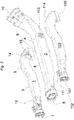
- the Fig. 1 shows as part of an air guide assembly for a motor vehicle, a first air duct 1, wherein the air duct 1 has an elongated channel wall 3, which defines a cavity 5 for conducting the air, which is between at least one air inlet opening 7 and at least one air outlet opening 9.
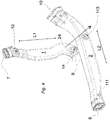
- FIG. 2 shows a separate second air duct 2, wherein the air duct 2 has an elongated channel wall 4, which defines a cavity 6 for guiding the air, which lies between at least one air inlet opening 8 and at least one air outlet opening 10.
- the air ducts 1, 2 can be connected to each other via a first locking connection 11, 12 of a first locking element 11 and a first locking counter-element 12 and at least a second locking connection 13, 14 of a second locking element 13 and a second locking counter-element 14.
- the latching connections 11, 12, 13, 14 are integrally formed from the respective channel wall 3, 4 of the first air duct 1 and the second air duct 2.
- the latching connections 11, 12, 13, 14 are each arranged so that the air ducts 1, 2 can be arranged side by side in their longitudinal extension directions L1, L2, to form a multi-channel air ducting arrangement.
- the in Fig. 2 shown second air duct 2 would have to be rotated accordingly to position the respective air inlet openings 7, 8 of the air ducts 1, 2 next to each other.
- the locking elements 11 and 13 in the illustration according to Fig. 2 no longer visible, are in Fig. 1 and Fig. 2 the corresponding contacting sides of the air ducts 1, 2 shown.
- the second latching element 13 is designed as a latching dome and executed on the second air duct 2.
- the latching dome 13 may also be formed on the first air duct 1.
- the second locking counter-element 14 is formed as a Rastdom technique and formed in accordance with the first air duct 1.
- the second detent counter element 14 is correspondingly designed as a Rastdom technique and formed on the second air duct 2.
- the latching dome 13 has an indentation 20 formed on the dome flank 21 which forms the latching dome 13, the end region of which is at a distance X from the dome flank 21.
- the formation 20 in this case forms a projecting from the mandril 21 locking projection. In the embodiment shown here, a further formation 20 is formed on the mandril 21.
- the Rastdomsuit 14 has an inlet opening 16 with different opening widths 16a, 16b.
- the longest opening width 16a of the inlet opening 16 is greater than or equal to the width b + n ⁇ X (b plus n times X, with n equal to the number of formations) of the locking dome 13 with the formation 20 or with the formations 20.
- the smallest opening width 16b is greater than or equal to the width b of the locking dome 13 and smaller than the width b + n ⁇ X of the locking dome 13 with the formation 20 or with the formations 20.
- the Rastdomness 14 has in the region of the smallest opening width 16 b at least one of the inlet opening 16 undercut formed Forming receptacle 24 for receiving the molding 20 on. Since in the embodiment shown here, the detent dome 13 has two formations 20, two Ausformungsabilityn 24 are provided accordingly.
- the inlet opening 16 is presently oval or elliptical, wherein also a rectangular or a combination of rectangular, oval or elliptical ausgestalteter geometry is conceivable.
- the latching dome 13 having a formation 20 and the latching dome receptacle 14 having an inlet opening 16 are designed and matched to one another in such a way that the second latching connection 13, 14 has a, preferably opposite, relative rotational movement R (cf. Fig. 6 ) of the air ducts 1, 2 can be locked to each other.
- the first air duct 1 and / or the second air duct 2 are manufactured in a blow molding process or in a thermoforming process. To illustrate the first latching connection 11, 12 and the second latching connection 13, 14 are in Fig.1 and in Fig.
- first latching connection 11, 12 may be formed as the second latching connection 13, 14 described above be. This increases the flexibility in the assembly of the air guide assembly, since it does not matter now which of the two locking connections 11, 12, 13, 14 can be latched via a rotational movement.
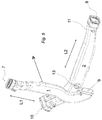
- the Fig. 3 shows an exploded view of the multi-channel air duct assembly and a representation of the multi-channel air duct assembly prior to their assembly.
- the air ducts 1, 2, 103 are in this case arranged side by side in their longitudinal extension directions, but not yet locked together.
- the in the Figures 1 and 2 Elements described for the reference numerals of the third air duct 103 are respectively increased by the number 100.
- Fig. 4 the air ducts 1 and 2 described in the above figures are shown, in which case first the shaping 20 or the formations 20 of the locking dome 13 in the direction of the longest opening width 16a of the inlet opening 16 of the Rastdom technique 14 is oriented 7 are.
- the orientation of the air ducts 1 and 2 and the shape 20 of the locking dome 13 and the formations 20 of the locking dome 13 in relation to the opening width 16a of the inlet opening 16 of the Rastdomsuit 14 is also in Fig. 5 presented from a different perspective.
- the longitudinal extension directions L1 and L2 of the two air ducts 1, 2 are in this case oriented approximately perpendicular to each other.
- Fig. 6 is the next step for assembling the multi-channel air duct assembly shown by the locking dome 13 inserted through the inlet opening 16 in the Rastdomage 14 and a, preferably opposite, relative rotational movement R of the air ducts 1, 2 to each other, the locking connection 11, 12 is latched by the Forming 20 or the formations 20 is rotated into the forming receptacle 24 or into the shaping receptacles 24 or become.
- the Fig. 6a shows this corresponding connection state in a cross section through the second latching connection 11, 12. In the following step, the first latching connection 11, 12 is locked.
- FIG. 7 is the three-dimensional representation of the multi-channel air duct assembly shown, which is formed by latching interconnected air ducts 1, 2 and 103.
- the air ducts 1, 2, 103 are connected to each other via the snap-in connections 11, 12, 13, 14, 111, 112 and 113, 114 with each other along their longitudinal extension directions.
- At least the second latching element 13 is formed as a latching dome and formed on the first air duct 1 or the second air duct 2 and at least the second locking counter-element 14 is formed as a Rastdom technique and is formed accordingly on the first air duct 1 or the second air duct 2.
- the latching dome 13 has at least one undercut 20 formed on the dome side 21, the end area of which is spaced from the dome flank 21 by a distance X.
- the Rastdomness 14 has an inlet opening 16 with different opening widths 16 a, 16 b, wherein the longest opening width 16a of the inlet opening 16 is greater than or equal to the width b + n ⁇ X of the locking dome 13 with the formation 20 or with the formations 20, and smallest opening width 16b is greater than or equal to the width b of the locking dome 13 and smaller than the width b + n ⁇ X of the locking dome 13 with the molding 20 or 20 with the formations.
- the detent dome 14 has at least one shaping receptacle 24 which undercut the inlet opening 16 to accommodate the formation 20 (cf. Fig. 1 to 3 ).
- the formation 20 of the locking dome 13 or the formations 20 of the locking dome 13 is / are first oriented in the direction of the longest opening width 16a of the inlet opening 16, then the locking dome 13 through the inlet opening 16 in the Rastdom technique 14 and inserted over a, preferably opposite, relative rotational movement R of the air ducts 1, 2 to each other, the second locking connection 13, 14 locked in which the formation 20 or the formations 20 is rotated into the Ausformungsage 24 or into the Ausformungsagen 24 or before then the first latching connection 11, 12 is latched (see. 4 to 6 ).
- first latching connection 11, 12 may be formed as the second latching connection 13, 14 described above. This increases the flexibility in the assembly of the air guide assembly, since it does not matter which of the two locking connections 11, 12, 13, 14 is locked by a rotational movement. Accordingly, the method described above then applies analogously to the first latching connection 11, 12.
Landscapes
- Physics & Mathematics (AREA)
- Thermal Sciences (AREA)
- Engineering & Computer Science (AREA)
- Mechanical Engineering (AREA)
- Air-Conditioning For Vehicles (AREA)
Applications Claiming Priority (1)
| Application Number | Priority Date | Filing Date | Title |
|---|---|---|---|
| DE102015108341.8A DE102015108341A1 (de) | 2015-05-27 | 2015-05-27 | Luftführungsanordnung für ein Kraftfahrzeug sowie Verfahren zur Herstellung einer Luftführungsanordnung für ein Kraftfahrzeug |
Publications (2)
| Publication Number | Publication Date |
|---|---|
| EP3098100A1 true EP3098100A1 (fr) | 2016-11-30 |
| EP3098100B1 EP3098100B1 (fr) | 2020-04-29 |
Family
ID=55527856
Family Applications (1)
| Application Number | Title | Priority Date | Filing Date |
|---|---|---|---|
| EP16159868.5A Active EP3098100B1 (fr) | 2015-05-27 | 2016-03-11 | Dispositif de guidage de l'air pour un vehicule automobile, ainsi que procede de fabrication d'un dispositif de guidage de l'air pour un vehicule automobile |
Country Status (2)
| Country | Link |
|---|---|
| EP (1) | EP3098100B1 (fr) |
| DE (1) | DE102015108341A1 (fr) |
Cited By (1)
| Publication number | Priority date | Publication date | Assignee | Title |
|---|---|---|---|---|
| US20220065554A1 (en) * | 2020-09-03 | 2022-03-03 | Ti Automotive Technology Center Gmbh | Pipe arrangement for transporting temperature control media |
Citations (5)
| Publication number | Priority date | Publication date | Assignee | Title |
|---|---|---|---|---|
| GB2332887A (en) * | 1997-11-19 | 1999-07-07 | Textron Automotive U K | Fluid reservoir and air duct |
| WO2002032702A2 (fr) * | 2000-10-18 | 2002-04-25 | Honda Giken Kogyo Kabushiki Kaisha | Conduite de climatiseur et son procede de montage |
| DE10137998A1 (de) | 2001-08-02 | 2003-02-13 | Bayerische Motoren Werke Ag | Rastverbindungsstruktur und hiermit versehene Leitungseinrichtung |
| EP2062759A1 (fr) * | 2007-11-20 | 2009-05-27 | Seat, S.A. | Alimentation d'air de climatisation pour boîtes à gants d'automobiles |
| US20110009045A1 (en) * | 2009-07-09 | 2011-01-13 | Beckley Daniel V | Vehicular Interior Assembly |
Family Cites Families (3)
| Publication number | Priority date | Publication date | Assignee | Title |
|---|---|---|---|---|
| US20090243322A1 (en) * | 2008-04-01 | 2009-10-01 | David F. MacNeil | Vehicle cargo space liner with snap-connected extension |
| DE102008045595B4 (de) * | 2008-09-03 | 2020-09-03 | Audi Ag | Kraftfahrzeug-Luftfiltersystem und zugehöriges Montageverfahren |
| CH702954B1 (de) * | 2010-04-12 | 2014-08-15 | Schwanden Kunststoff | Gekrümmte Doppelrohreinheit. |
-
2015
- 2015-05-27 DE DE102015108341.8A patent/DE102015108341A1/de not_active Withdrawn
-
2016
- 2016-03-11 EP EP16159868.5A patent/EP3098100B1/fr active Active
Patent Citations (5)
| Publication number | Priority date | Publication date | Assignee | Title |
|---|---|---|---|---|
| GB2332887A (en) * | 1997-11-19 | 1999-07-07 | Textron Automotive U K | Fluid reservoir and air duct |
| WO2002032702A2 (fr) * | 2000-10-18 | 2002-04-25 | Honda Giken Kogyo Kabushiki Kaisha | Conduite de climatiseur et son procede de montage |
| DE10137998A1 (de) | 2001-08-02 | 2003-02-13 | Bayerische Motoren Werke Ag | Rastverbindungsstruktur und hiermit versehene Leitungseinrichtung |
| EP2062759A1 (fr) * | 2007-11-20 | 2009-05-27 | Seat, S.A. | Alimentation d'air de climatisation pour boîtes à gants d'automobiles |
| US20110009045A1 (en) * | 2009-07-09 | 2011-01-13 | Beckley Daniel V | Vehicular Interior Assembly |
Cited By (5)
| Publication number | Priority date | Publication date | Assignee | Title |
|---|---|---|---|---|
| US20220065554A1 (en) * | 2020-09-03 | 2022-03-03 | Ti Automotive Technology Center Gmbh | Pipe arrangement for transporting temperature control media |
| EP3964372A1 (fr) * | 2020-09-03 | 2022-03-09 | TI Automotive Technology Center GmbH | Agencement de conduites pour le transport des milieux de mise à la température |
| EP3964374A1 (fr) * | 2020-09-03 | 2022-03-09 | TI Automotive Technology Center GmbH | Agencement de tube pour le transport des milieux de mise à la température |
| CN114321542A (zh) * | 2020-09-03 | 2022-04-12 | Ti汽车技术中心有限责任公司 | 用于输送温控介质的管道装置 |
| US12235051B2 (en) * | 2020-09-03 | 2025-02-25 | Ti Automotive Technology Center Gmbh | Pipe arrangement for transporting temperature control media |
Also Published As
| Publication number | Publication date |
|---|---|
| DE102015108341A1 (de) | 2016-12-01 |
| EP3098100B1 (fr) | 2020-04-29 |
Similar Documents
| Publication | Publication Date | Title |
|---|---|---|
| DE102007040812B4 (de) | Kabelschutz- und -führungsvorrichtung vom Falttyp | |
| EP1254043B1 (fr) | Piece pour un vehicule a moteur | |
| EP1675766B1 (fr) | Element composite, notamment une traverse | |
| DE102008016490A1 (de) | Kabelschutz und Führungsvorrichtung | |
| EP2945813B1 (fr) | Grille d'aération présentant un élément de guidage d'air, et procédé de production d'une telle grille d'aération | |
| DE10046120A1 (de) | Bautteil für ein Kraftfahrzeug | |
| DE102013000628B4 (de) | Halterahmen einer Frischluftklappe eines Kraftfahrzeuges sowie Frischluftklappe mit Halterahmen | |
| DE102015113538A1 (de) | HAVC-Kanal mit Schwenkbogen | |
| EP3366985B1 (fr) | Phare de véhicule pourvu d'un canal à câbles et procédé de fabrication correspondant | |
| EP3098100B1 (fr) | Dispositif de guidage de l'air pour un vehicule automobile, ainsi que procede de fabrication d'un dispositif de guidage de l'air pour un vehicule automobile | |
| DE102010023528A1 (de) | Luftausströmvorrichtung für ein Fahrzeug | |
| EP2129506A1 (fr) | Procédé de production d'un système d'étanchéité, notamment pour automobile, comprenant un élément d'étanchéité et un support, et système d'étanchéité correspondant | |
| EP3034337B1 (fr) | Systeme de conduite d'air pour un vehicule automobile | |
| DE102013216581A1 (de) | Kabelkanal sowie Verfahren zum Herstellen eines dreidimensional verlaufenden Kabelkanals | |
| EP4196330B1 (fr) | Pièce extrudée, boîtier de batterie ayant une pièce extrudée, procédé de production d'une pièce extrudée, filière d'extrusion | |
| DE202014002016U1 (de) | Luftausströmer | |
| DE10210968C1 (de) | Gebogenes Strangpreßprofil | |
| EP3319827A1 (fr) | Module de toit pour véhicule automobile | |
| DE10127650A1 (de) | Vorrichtung zur mechanischen Steuerung von Elementen einer Fahrzeugbelüftungsanlage | |
| EP4588698A1 (fr) | Système de guidage d'air pour un véhicule automobile | |
| EP4574478A1 (fr) | Système de guidage d'air pour un véhicule automobile | |
| DE102018115568A1 (de) | Befestigungssystem für abdeckungsbauteile eines lenkrads, lenkrad sowie verfahren zur herstellung eines lenkrads | |
| DE102004063718B4 (de) | Verfahren zur Herstellung von Verdrahtungskanälen und danach hergestellter Verdrahtungskanal | |
| DE102014218935A1 (de) | Luftverteilungseinrichtung | |
| DE102017208724A1 (de) | Bauteilsystem zur Spalt-Minimierung, Verfahren zur Herstellung eines Bauteilsystems und Kraftfahrzeug mit einem Bauteilsystem |
Legal Events
| Date | Code | Title | Description |
|---|---|---|---|
| PUAI | Public reference made under article 153(3) epc to a published international application that has entered the european phase |
Free format text: ORIGINAL CODE: 0009012 |
|
| AK | Designated contracting states |
Kind code of ref document: A1 Designated state(s): AL AT BE BG CH CY CZ DE DK EE ES FI FR GB GR HR HU IE IS IT LI LT LU LV MC MK MT NL NO PL PT RO RS SE SI SK SM TR |
|
| AX | Request for extension of the european patent |
Extension state: BA ME |
|
| STAA | Information on the status of an ep patent application or granted ep patent |
Free format text: STATUS: REQUEST FOR EXAMINATION WAS MADE |
|
| 17P | Request for examination filed |
Effective date: 20170530 |
|
| RBV | Designated contracting states (corrected) |
Designated state(s): AL AT BE BG CH CY CZ DE DK EE ES FI FR GB GR HR HU IE IS IT LI LT LU LV MC MK MT NL NO PL PT RO RS SE SI SK SM TR |
|
| STAA | Information on the status of an ep patent application or granted ep patent |
Free format text: STATUS: EXAMINATION IS IN PROGRESS |
|
| 17Q | First examination report despatched |
Effective date: 20181010 |
|
| GRAP | Despatch of communication of intention to grant a patent |
Free format text: ORIGINAL CODE: EPIDOSNIGR1 |
|
| STAA | Information on the status of an ep patent application or granted ep patent |
Free format text: STATUS: GRANT OF PATENT IS INTENDED |
|
| INTG | Intention to grant announced |
Effective date: 20200131 |
|
| GRAS | Grant fee paid |
Free format text: ORIGINAL CODE: EPIDOSNIGR3 |
|
| GRAA | (expected) grant |
Free format text: ORIGINAL CODE: 0009210 |
|
| STAA | Information on the status of an ep patent application or granted ep patent |
Free format text: STATUS: THE PATENT HAS BEEN GRANTED |
|
| AK | Designated contracting states |
Kind code of ref document: B1 Designated state(s): AL AT BE BG CH CY CZ DE DK EE ES FI FR GB GR HR HU IE IS IT LI LT LU LV MC MK MT NL NO PL PT RO RS SE SI SK SM TR |
|
| REG | Reference to a national code |
Ref country code: GB Ref legal event code: FG4D Free format text: NOT ENGLISH |
|
| REG | Reference to a national code |
Ref country code: CH Ref legal event code: EP |
|
| REG | Reference to a national code |
Ref country code: AT Ref legal event code: REF Ref document number: 1262764 Country of ref document: AT Kind code of ref document: T Effective date: 20200515 |
|
| REG | Reference to a national code |
Ref country code: DE Ref legal event code: R096 Ref document number: 502016009711 Country of ref document: DE |
|
| REG | Reference to a national code |
Ref country code: IE Ref legal event code: FG4D Free format text: LANGUAGE OF EP DOCUMENT: GERMAN |
|
| REG | Reference to a national code |
Ref country code: NL Ref legal event code: MP Effective date: 20200429 |
|
| REG | Reference to a national code |
Ref country code: LT Ref legal event code: MG4D |
|
| PG25 | Lapsed in a contracting state [announced via postgrant information from national office to epo] |
Ref country code: PT Free format text: LAPSE BECAUSE OF FAILURE TO SUBMIT A TRANSLATION OF THE DESCRIPTION OR TO PAY THE FEE WITHIN THE PRESCRIBED TIME-LIMIT Effective date: 20200831 Ref country code: GR Free format text: LAPSE BECAUSE OF FAILURE TO SUBMIT A TRANSLATION OF THE DESCRIPTION OR TO PAY THE FEE WITHIN THE PRESCRIBED TIME-LIMIT Effective date: 20200730 Ref country code: IS Free format text: LAPSE BECAUSE OF FAILURE TO SUBMIT A TRANSLATION OF THE DESCRIPTION OR TO PAY THE FEE WITHIN THE PRESCRIBED TIME-LIMIT Effective date: 20200829 Ref country code: SE Free format text: LAPSE BECAUSE OF FAILURE TO SUBMIT A TRANSLATION OF THE DESCRIPTION OR TO PAY THE FEE WITHIN THE PRESCRIBED TIME-LIMIT Effective date: 20200429 Ref country code: NO Free format text: LAPSE BECAUSE OF FAILURE TO SUBMIT A TRANSLATION OF THE DESCRIPTION OR TO PAY THE FEE WITHIN THE PRESCRIBED TIME-LIMIT Effective date: 20200729 Ref country code: FI Free format text: LAPSE BECAUSE OF FAILURE TO SUBMIT A TRANSLATION OF THE DESCRIPTION OR TO PAY THE FEE WITHIN THE PRESCRIBED TIME-LIMIT Effective date: 20200429 Ref country code: LT Free format text: LAPSE BECAUSE OF FAILURE TO SUBMIT A TRANSLATION OF THE DESCRIPTION OR TO PAY THE FEE WITHIN THE PRESCRIBED TIME-LIMIT Effective date: 20200429 |
|
| RAP2 | Party data changed (patent owner data changed or rights of a patent transferred) |
Owner name: REHAU AG + CO |
|
| PG25 | Lapsed in a contracting state [announced via postgrant information from national office to epo] |
Ref country code: BG Free format text: LAPSE BECAUSE OF FAILURE TO SUBMIT A TRANSLATION OF THE DESCRIPTION OR TO PAY THE FEE WITHIN THE PRESCRIBED TIME-LIMIT Effective date: 20200729 Ref country code: LV Free format text: LAPSE BECAUSE OF FAILURE TO SUBMIT A TRANSLATION OF THE DESCRIPTION OR TO PAY THE FEE WITHIN THE PRESCRIBED TIME-LIMIT Effective date: 20200429 Ref country code: RS Free format text: LAPSE BECAUSE OF FAILURE TO SUBMIT A TRANSLATION OF THE DESCRIPTION OR TO PAY THE FEE WITHIN THE PRESCRIBED TIME-LIMIT Effective date: 20200429 Ref country code: HR Free format text: LAPSE BECAUSE OF FAILURE TO SUBMIT A TRANSLATION OF THE DESCRIPTION OR TO PAY THE FEE WITHIN THE PRESCRIBED TIME-LIMIT Effective date: 20200429 |
|
| PG25 | Lapsed in a contracting state [announced via postgrant information from national office to epo] |
Ref country code: NL Free format text: LAPSE BECAUSE OF FAILURE TO SUBMIT A TRANSLATION OF THE DESCRIPTION OR TO PAY THE FEE WITHIN THE PRESCRIBED TIME-LIMIT Effective date: 20200429 Ref country code: AL Free format text: LAPSE BECAUSE OF FAILURE TO SUBMIT A TRANSLATION OF THE DESCRIPTION OR TO PAY THE FEE WITHIN THE PRESCRIBED TIME-LIMIT Effective date: 20200429 |
|
| PG25 | Lapsed in a contracting state [announced via postgrant information from national office to epo] |
Ref country code: SM Free format text: LAPSE BECAUSE OF FAILURE TO SUBMIT A TRANSLATION OF THE DESCRIPTION OR TO PAY THE FEE WITHIN THE PRESCRIBED TIME-LIMIT Effective date: 20200429 Ref country code: EE Free format text: LAPSE BECAUSE OF FAILURE TO SUBMIT A TRANSLATION OF THE DESCRIPTION OR TO PAY THE FEE WITHIN THE PRESCRIBED TIME-LIMIT Effective date: 20200429 Ref country code: IT Free format text: LAPSE BECAUSE OF FAILURE TO SUBMIT A TRANSLATION OF THE DESCRIPTION OR TO PAY THE FEE WITHIN THE PRESCRIBED TIME-LIMIT Effective date: 20200429 Ref country code: DK Free format text: LAPSE BECAUSE OF FAILURE TO SUBMIT A TRANSLATION OF THE DESCRIPTION OR TO PAY THE FEE WITHIN THE PRESCRIBED TIME-LIMIT Effective date: 20200429 Ref country code: RO Free format text: LAPSE BECAUSE OF FAILURE TO SUBMIT A TRANSLATION OF THE DESCRIPTION OR TO PAY THE FEE WITHIN THE PRESCRIBED TIME-LIMIT Effective date: 20200429 Ref country code: CZ Free format text: LAPSE BECAUSE OF FAILURE TO SUBMIT A TRANSLATION OF THE DESCRIPTION OR TO PAY THE FEE WITHIN THE PRESCRIBED TIME-LIMIT Effective date: 20200429 Ref country code: ES Free format text: LAPSE BECAUSE OF FAILURE TO SUBMIT A TRANSLATION OF THE DESCRIPTION OR TO PAY THE FEE WITHIN THE PRESCRIBED TIME-LIMIT Effective date: 20200429 |
|
| REG | Reference to a national code |
Ref country code: DE Ref legal event code: R097 Ref document number: 502016009711 Country of ref document: DE |
|
| PG25 | Lapsed in a contracting state [announced via postgrant information from national office to epo] |
Ref country code: PL Free format text: LAPSE BECAUSE OF FAILURE TO SUBMIT A TRANSLATION OF THE DESCRIPTION OR TO PAY THE FEE WITHIN THE PRESCRIBED TIME-LIMIT Effective date: 20200429 Ref country code: SK Free format text: LAPSE BECAUSE OF FAILURE TO SUBMIT A TRANSLATION OF THE DESCRIPTION OR TO PAY THE FEE WITHIN THE PRESCRIBED TIME-LIMIT Effective date: 20200429 |
|
| PLBE | No opposition filed within time limit |
Free format text: ORIGINAL CODE: 0009261 |
|
| STAA | Information on the status of an ep patent application or granted ep patent |
Free format text: STATUS: NO OPPOSITION FILED WITHIN TIME LIMIT |
|
| 26N | No opposition filed |
Effective date: 20210201 |
|
| PG25 | Lapsed in a contracting state [announced via postgrant information from national office to epo] |
Ref country code: SI Free format text: LAPSE BECAUSE OF FAILURE TO SUBMIT A TRANSLATION OF THE DESCRIPTION OR TO PAY THE FEE WITHIN THE PRESCRIBED TIME-LIMIT Effective date: 20200429 |
|
| PG25 | Lapsed in a contracting state [announced via postgrant information from national office to epo] |
Ref country code: MC Free format text: LAPSE BECAUSE OF FAILURE TO SUBMIT A TRANSLATION OF THE DESCRIPTION OR TO PAY THE FEE WITHIN THE PRESCRIBED TIME-LIMIT Effective date: 20200429 |
|
| REG | Reference to a national code |
Ref country code: CH Ref legal event code: PL |
|
| GBPC | Gb: european patent ceased through non-payment of renewal fee |
Effective date: 20210311 |
|
| REG | Reference to a national code |
Ref country code: BE Ref legal event code: MM Effective date: 20210331 |
|
| PG25 | Lapsed in a contracting state [announced via postgrant information from national office to epo] |
Ref country code: GB Free format text: LAPSE BECAUSE OF NON-PAYMENT OF DUE FEES Effective date: 20210311 Ref country code: FR Free format text: LAPSE BECAUSE OF NON-PAYMENT OF DUE FEES Effective date: 20210331 Ref country code: IE Free format text: LAPSE BECAUSE OF NON-PAYMENT OF DUE FEES Effective date: 20210311 Ref country code: CH Free format text: LAPSE BECAUSE OF NON-PAYMENT OF DUE FEES Effective date: 20210331 Ref country code: LI Free format text: LAPSE BECAUSE OF NON-PAYMENT OF DUE FEES Effective date: 20210331 Ref country code: LU Free format text: LAPSE BECAUSE OF NON-PAYMENT OF DUE FEES Effective date: 20210311 |
|
| REG | Reference to a national code |
Ref country code: DE Ref legal event code: R081 Ref document number: 502016009711 Country of ref document: DE Owner name: REHAU AUTOMOTIVE SE & CO. KG, DE Free format text: FORMER OWNER: REHAU AG + CO, 95111 REHAU, DE Ref country code: DE Ref legal event code: R081 Ref document number: 502016009711 Country of ref document: DE Owner name: RESRG AUTOMOTIVE SE & CO. KG, DE Free format text: FORMER OWNER: REHAU AG + CO, 95111 REHAU, DE |
|
| REG | Reference to a national code |
Ref country code: AT Ref legal event code: MM01 Ref document number: 1262764 Country of ref document: AT Kind code of ref document: T Effective date: 20210311 |
|
| PG25 | Lapsed in a contracting state [announced via postgrant information from national office to epo] |
Ref country code: BE Free format text: LAPSE BECAUSE OF NON-PAYMENT OF DUE FEES Effective date: 20210331 |
|
| PG25 | Lapsed in a contracting state [announced via postgrant information from national office to epo] |
Ref country code: AT Free format text: LAPSE BECAUSE OF NON-PAYMENT OF DUE FEES Effective date: 20210311 |
|
| PG25 | Lapsed in a contracting state [announced via postgrant information from national office to epo] |
Ref country code: HU Free format text: LAPSE BECAUSE OF FAILURE TO SUBMIT A TRANSLATION OF THE DESCRIPTION OR TO PAY THE FEE WITHIN THE PRESCRIBED TIME-LIMIT; INVALID AB INITIO Effective date: 20160311 |
|
| PG25 | Lapsed in a contracting state [announced via postgrant information from national office to epo] |
Ref country code: CY Free format text: LAPSE BECAUSE OF FAILURE TO SUBMIT A TRANSLATION OF THE DESCRIPTION OR TO PAY THE FEE WITHIN THE PRESCRIBED TIME-LIMIT Effective date: 20200429 |
|
| P01 | Opt-out of the competence of the unified patent court (upc) registered |
Effective date: 20230529 |
|
| PG25 | Lapsed in a contracting state [announced via postgrant information from national office to epo] |
Ref country code: MK Free format text: LAPSE BECAUSE OF FAILURE TO SUBMIT A TRANSLATION OF THE DESCRIPTION OR TO PAY THE FEE WITHIN THE PRESCRIBED TIME-LIMIT Effective date: 20200429 |
|
| PG25 | Lapsed in a contracting state [announced via postgrant information from national office to epo] |
Ref country code: MT Free format text: LAPSE BECAUSE OF FAILURE TO SUBMIT A TRANSLATION OF THE DESCRIPTION OR TO PAY THE FEE WITHIN THE PRESCRIBED TIME-LIMIT Effective date: 20200429 |
|
| REG | Reference to a national code |
Ref country code: DE Ref legal event code: R081 Ref document number: 502016009711 Country of ref document: DE Owner name: RESRG AUTOMOTIVE SE & CO. KG, DE Free format text: FORMER OWNER: REHAU AUTOMOTIVE SE & CO. KG, 95111 REHAU, DE |
|
| PG25 | Lapsed in a contracting state [announced via postgrant information from national office to epo] |
Ref country code: TR Free format text: LAPSE BECAUSE OF FAILURE TO SUBMIT A TRANSLATION OF THE DESCRIPTION OR TO PAY THE FEE WITHIN THE PRESCRIBED TIME-LIMIT Effective date: 20200429 |
|
| PGFP | Annual fee paid to national office [announced via postgrant information from national office to epo] |
Ref country code: DE Payment date: 20260331 Year of fee payment: 11 |