EP3098113A1 - Laderaum mit paletten-führung - Google Patents
Laderaum mit paletten-führung Download PDFInfo
- Publication number
- EP3098113A1 EP3098113A1 EP16170123.0A EP16170123A EP3098113A1 EP 3098113 A1 EP3098113 A1 EP 3098113A1 EP 16170123 A EP16170123 A EP 16170123A EP 3098113 A1 EP3098113 A1 EP 3098113A1
- Authority
- EP
- European Patent Office
- Prior art keywords
- cargo space
- guide
- boundary plate
- guiding
- run
- Prior art date
- Legal status (The legal status is an assumption and is not a legal conclusion. Google has not performed a legal analysis and makes no representation as to the accuracy of the status listed.)
- Granted
Links
- 238000000034 method Methods 0.000 claims description 4
- 230000000284 resting effect Effects 0.000 description 3
- 208000035126 Facies Diseases 0.000 description 1
- 239000004677 Nylon Substances 0.000 description 1
- 239000003292 glue Substances 0.000 description 1
- 238000002347 injection Methods 0.000 description 1
- 239000007924 injection Substances 0.000 description 1
- 238000001746 injection moulding Methods 0.000 description 1
- 239000000463 material Substances 0.000 description 1
- 239000002184 metal Substances 0.000 description 1
- 229920001778 nylon Polymers 0.000 description 1
- 239000004033 plastic Substances 0.000 description 1
- 229920002994 synthetic fiber Polymers 0.000 description 1
- 239000002023 wood Substances 0.000 description 1
Images

Classifications
-
- B—PERFORMING OPERATIONS; TRANSPORTING
- B60—VEHICLES IN GENERAL
- B60P—VEHICLES ADAPTED FOR LOAD TRANSPORTATION OR TO TRANSPORT, TO CARRY, OR TO COMPRISE SPECIAL LOADS OR OBJECTS
- B60P7/00—Securing or covering of load on vehicles
-
- B—PERFORMING OPERATIONS; TRANSPORTING
- B60—VEHICLES IN GENERAL
- B60P—VEHICLES ADAPTED FOR LOAD TRANSPORTATION OR TO TRANSPORT, TO CARRY, OR TO COMPRISE SPECIAL LOADS OR OBJECTS
- B60P1/00—Vehicles predominantly for transporting loads and modified to facilitate loading, consolidating the load, or unloading
- B60P1/64—Vehicles predominantly for transporting loads and modified to facilitate loading, consolidating the load, or unloading the load supporting or containing element being readily removable
- B60P1/6418—Vehicles predominantly for transporting loads and modified to facilitate loading, consolidating the load, or unloading the load supporting or containing element being readily removable the load-transporting element being a container or similar
- B60P1/649—Guiding means for the load-transporting element
Definitions
- the invention relates to a cargo space.
- Cargo spaces in particular for freighters, trucks and/or trailer trucks such as a curtainsider, are known from the state of the art and are typically used for accommodating cargo for transport, such as goods resting on pallets. During loading and unloading, the pallets with the goods resting thereon are regularly slid into and out of the cargo space.
- the known cargo spaces in particular for curtainsiders, comprise a floor where posts, also called uprights, are provided next to each other on either side of the floor.
- the posts serve for fastening and confining the cargo, but can also be removed or folded away for loading or unloading cargo.
- the posts extend upwards and are provided with a receiving provision for receiving an end of an elongate boundary plate.
- the known receiving provisions generally comprise two flanges between which the end of the elongate boundary plate is positioned.
- the elongate boundary plate extends in the length direction of the cargo space between two posts.
- the elongate boundary plate has a guiding surface facing towards the longitudinal, vertical median plane of the cargo space.
- the boundary plate is suitable in particular for guiding the pallets therealong substantially in the length direction of the cargo space. Additionally, the boundary plate also prevents cargo from falling out via the sides of the cargo space.
- a drawback of the above-mentioned cargo spaces is that during loading and unloading, that is, the sliding of pallets with goods resting thereon into and out of the cargo space, it regularly occurs that a pallet is caught behind a post so that the pallet may sustain damage.
- pallets collide with, for instance, the inner flange of the post so that a pallet is caught behind it.
- the goods on top of the pallet may topple over, as a result of which the user loses relatively much time re-stacking the goods on the pallet.
- the goods will thereby get seriously damaged, especially when glassware goods are involved.
- the object of the invention is to counteract one or more of the drawbacks mentioned.
- the invention provides a cargo space according to the preamble of claim 1, characterized in that the cargo space further comprises at least one guide which is provided with a first run-on surface for during use guiding a pallet at least partly away from the guiding surface of the boundary plate.
- a cargo space that comprises a guide can elegantly prevent a pallet from getting caught behind the respective post, for instance the inner flange, and possibly sustaining damage as a result, or prevent the goods located on top of the pallet from possibly tipping over as a result.
- the pallet is, at least partly, guided away from the guiding surface of the boundary plate towards the longitudinal vertical median plane of the cargo space. This is to say that the pallet is guided via the run-on surface of the guide to the middle of the cargo space.
- the run-on surface preferably runs up in the length direction of the cargo space and/or in the direction in which the pallets are slid into the cargo space.
- the guide is provided on the elongate boundary plate, for instance on the guiding surface thereof. It is also possible that the guide is situated, for instance, on the floor and/or on the respective post.
- the cargo space can preferably be provided with a plurality of boundary plates which are disposed on top of each other at the sides of the cargo space.
- each boundary plate can comprise a guide. What can be achieved in this manner is that, during use, pallets stacked onto each other can at least partly be guided away from the guiding surface of one of the boundary plates.
- the guide can be provided near an end of the boundary plate, for instance near the end of the boundary plate which is received by the receiving provision.
- the guide can be located approximately 1-5 cm from the end of the boundary plate and/or post. What can be achieved by placing the guide near the end of the boundary plate is that the pallet guided away from the guiding surface can move past the post, and in any case cannot return to its original position before the pallet has passed the post.
- the guide can comprise a second run-on surface which is substantially opposite to the first run-on surface. This can prevent a pallet which is being moved substantially in the opposite direction from getting caught behind the guide.
- the guide can comprise a convex surface which defines the first run-on surface.
- the convex surface can also define the second run-on surface.
- the convex surface can be formed substantially as a segment of a sphere and is preferably symmetrical.
- the guide has a different surface, for example, in the form of a rectangle, square, triangle or a segment of a pyramid.
- an angle that can be greater than 120°, preferably greater than 135°, and more preferably approximately in the range of 150-170°, for instance 160°.
- the guide comprises a top, with the distance from the top to the longitudinal vertical median plane of the cargo space being less than or equal to the distance from the post to the longitudinal vertical median plane of the cargo space.
- the invention further relates to an elongate boundary plate for, during use, guiding pallets in a cargo space, comprising an elongate boundary body which is provided with a guide, preferably at least at one end of the elongate boundary body, while the guide is provided with a run-on surface for, during use, guiding a pallet at least partly away from a guiding surface of the boundary plate.
- the invention further relates to a guide for, during use, guiding a pallet, at least partly, away from a guiding surface of a boundary plate in a cargo space, comprising a first run-on surface, the guide being designed for fastening on the guiding surface of the boundary plate.
- the guide can also comprise a second run-on surface. Additionally, the guide can also comprise a convex surface, preferably a segment of a sphere.
- the invention further relates to a vehicle, preferably a motor vehicle, a semitrailer or a trailer, provided with a cargo space as described hereinabove.
- the invention further relates to a method comprising the steps of providing a cargo space which can comprise a chamber, preferably a cargo space as described hereinabove, having an elongate boundary plate on the side.
- a guide can be arranged, in such a manner that, during use, a pallet is, at least partly, guided away from a guiding surface of the elongate boundary plate.
- the guide can be arranged on the guiding surface of the boundary plate, preferably at both ends of the guiding surface of the boundary plate.
- the guide can comprise a first and a second run-on surface and/or have a symmetrical shape.
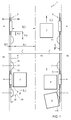
- a top plan view is shown of a cargo space 1 of a curtainsider for accommodating pallets 3.
- the cargo space 1 is, for example, a chamber and comprises a floor 2 on which the pallets 3 can be slid in the direction L 1 or in the direction L 2 for loading and unloading cargo.
- the cargo space depicted in Fig. 1 is approximately 14 meters long and 2.5 meters wide.
- posts 4 are provided which extend upwards.
- a tarpaulin curtain 13 is arranged to protect and/or hold the cargo within the cargo space 1.
- the posts 4 are further provided with a receiving provision 5 for receiving an end 6 of an elongate boundary plate 7.
- the receiving provision 5 comprises two flanges 8a, 8b between which the boundary plate 7 can be received.
- one elongate boundary plate 7 extends in the length direction of the cargo space 1.
- the boundary plate can have a height of approximately 10-20 cm, preferably approximately 15 cm.
- the cargo space is implemented with a plurality of boundary plates 7 positioned one on top of the other. These boundary plates 7 can comprise a boundary body. Further, these boundary plates can be implemented as wooden planks.
- the boundary plate 7 is provided with a guiding surface 9 which facies towards the longitudinal vertical median plane 10 of the cargo space 1.
- the guiding surface 9 and the longitudinal vertical median plane 10 can run substantially parallel to each other.
- the boundary plate 7 is suitable for guiding pallets 3 therealong substantially in the length direction of the cargo space 1, such that the movement of the pallets 3 within the cargo space 1 is limited. For instance, the pallets cannot fall out via the sides of the cargo space.
- the cargo space 1 further comprises at least one guide 11 which is provided with a first run-on surface 12, such that a pallet 3 during use is at least partly guided away from the guiding surface 9 of the boundary plate 7. This is to say that when the pallet 3 is seeking to pass the guide 11 via the boundary plate 7, the pallet 3 is pushed inwards, towards the longitudinal vertical median plane 10 so as to prevent the pallet 3 getting caught behind the respective posts 4.
- the guide 11 may be manufactured of a durable material such as Nylon so that it is well-resistant to any impacts of pallets 3, and/or of another synthetic material.
- the guide may also be made of metal or wood.
- the guide 11 can be manufactured by injection molding.
- the guide 11 may be designed for fastening on the guiding surface of the boundary plate. Fastening may be done, for instance, through fastening means such as, for example, glue, screws or nails.
- the guide 11 is provided on the elongate boundary plate 7, preferably on the guiding surface 9 thereof.
- the guide 11 may be provided near an end 6 of the elongate boundary plate 7.
- the distance Y 2 between the guide and the post is here, for example, 1-5 cm, and preferably approximately 2 cm.
- Figures 1 and 2 further show that the guide comprises a second run-on surface 14.
- the second run-on surface serves, for instance, to prevent a pallet that is being moved in substantially the opposite direction L 1 or L 2 from getting caught on the guide 11.
- the guide 11 has a convex surface, preferably a segment of a sphere, which defines the first run-on surface 12 and also defines the second run-on surface 14.
- the guide 11 is designed with a diameter of 5-20 cm, preferably 8-15 cm and more preferably approximately 10 cm.
- the guide also has a thickness which can be approximately 2 mm at the edge of the guide and can run up to approximately 1-1.5 cm X 3 in the center of the sphere. The thickness/diameter ratio of the guide can vary in the range of 0.01-0.3.
- ⁇ is included between the run-on surface and the guiding surface 9 of the elongate boundary plate 7. This angle can vary in the range of 100°-170°, is preferably greater than 120°, and more preferably greater than 135°.
- That the angle ⁇ mentioned can vary in the range of 100°-170°, and preferably can be greater than 120°, and more preferably can even be greater than 135°, may, at least in the case of a convex first run-on surface 12, be construed to mean at least that, when viewed from above, the tangent 120 to this first run-on surface 12 that includes the smallest angle with the elongate boundary plate 7 is between 100° and 170°, and preferably can be greater than 120°, and more preferably can be greater than 135°.
- the guide 11 can be provided with a raised edge 110, for instance as is the case in the exemplary embodiment shown.
- This raised edge 110 can for instance be substantially transverse to the length direction of the guide 9.
- the raised edge 110 is preferably relatively narrow, so that a pallet or cargo provided thereon can be prevented from butting against it.
- the raised edge 110 preferably does not extend farther than, for instance, 10 mm, more preferably not farther than 5 mm, still more preferably extends less than 3 mm or less than 2 mm, as, for instance, approximately 1.5 mm, approximately 1 mm or approximately 0.5 mm.
- the angle ⁇ between the raised edge 110 and the guiding surface 9 of the elongate boundary plate 7 can preferably be greater than 90°, and be, for example, in the range of 100°-170°, and preferably be greater than 120°, and more preferably even be greater than 135°.
- the angle ⁇ between the raised edge 110 and the guiding surface 9 is relatively great, for instance greater than 90° or even greater than 135°, this can prevent a pallet 3 or cargo provided thereon from possibly getting caught behind the raised edge 110, and the pallet 3, cargo and/or guide 11 from getting damaged. This can be advantageous, for instance in the case of a synthetic plastic and/or injection molded guide 11.
- the guide 11 comprises a top 15, with the distance X 1 from the top 15 to the longitudinal vertical median plane 10 of the cargo space being less than or equal to the distance X 2 from the post to the longitudinal vertical median plane 10 of the cargo space.
- the distance from the flange 8b to the longitudinal vertical median plane 10 is greater than or equal to the distance X 1 from the top to the longitudinal vertical median plane 10 of the cargo space.
- the thickness X 3 of the top 15 of the guide can be 1-3 cm, preferably approximately 1.5 cm.
- the distance Y 1 from the top 15 of the guide to the posts 4 can be approximately 10-20 cm to ensure that the passing pallet does not get caught behind the respective posts 4.
- the ratio X 3 /Y 1 can be in the range of 0.05-2.5, preferably 0.1-1.5.
- the guide 11 is fastened to the guiding surface 9 of the boundary plate, near the end 6. Fastening can be done as represented, by means of a screw. It is noted that the guide can also be fastened, for instance, to the floor 2 or to the post, such that the first run-on surface, in particular the edge of the first run-on surface, is located on the guiding surface 9.
- boundary plates 7 are provided which can each contain a guide 11.
Landscapes
- Engineering & Computer Science (AREA)
- Transportation (AREA)
- Mechanical Engineering (AREA)
- Pallets (AREA)
- Warehouses Or Storage Devices (AREA)
Applications Claiming Priority (1)
| Application Number | Priority Date | Filing Date | Title |
|---|---|---|---|
| NL2014825A NL2014825B1 (nl) | 2015-05-19 | 2015-05-19 | Vrachtruimte met palletgeleider. |
Publications (2)
| Publication Number | Publication Date |
|---|---|
| EP3098113A1 true EP3098113A1 (de) | 2016-11-30 |
| EP3098113B1 EP3098113B1 (de) | 2020-04-08 |
Family
ID=55178214
Family Applications (1)
| Application Number | Title | Priority Date | Filing Date |
|---|---|---|---|
| EP16170123.0A Active EP3098113B1 (de) | 2015-05-19 | 2016-05-18 | Laderaum mit paletten-führung |
Country Status (2)
| Country | Link |
|---|---|
| EP (1) | EP3098113B1 (de) |
| NL (1) | NL2014825B1 (de) |
Cited By (2)
| Publication number | Priority date | Publication date | Assignee | Title |
|---|---|---|---|---|
| EP3708426A1 (de) * | 2019-03-11 | 2020-09-16 | Helmut Fliegl | Ladungssicherungsbalken |
| BE1028140B1 (nl) * | 2020-03-11 | 2021-10-11 | A & D Trucks & Trailers Opbouw Nv | Zeiloplegger met verstevigde voor- en achterkader en werkwijze voor laden van dergelijke zeiloplegger |
Citations (5)
| Publication number | Priority date | Publication date | Assignee | Title |
|---|---|---|---|---|
| US2579774A (en) * | 1949-11-03 | 1951-12-25 | Hobbs Mfg Company | Vehicle side rack |
| US4756659A (en) * | 1987-01-06 | 1988-07-12 | Bader Samuel M | Automated load and unload highway trailer |
| US5320396A (en) * | 1992-02-13 | 1994-06-14 | Petelka Brian W | Stake for flatbed trailers |
| DE102012214277A1 (de) * | 2012-08-10 | 2014-02-13 | Burg Silvergreen Gmbh | Pufferelement zum Schutz eines Wandsegments |
| US20140210226A1 (en) * | 2013-01-28 | 2014-07-31 | Kenny Cobb | Protector guard for truck or trailer |
Family Cites Families (2)
| Publication number | Priority date | Publication date | Assignee | Title |
|---|---|---|---|---|
| GB426982A (en) * | 1934-01-31 | 1935-04-12 | Frank George Woollard | Improvements relating to road vehicle wheels |
| JP3852765B2 (ja) * | 2002-10-15 | 2006-12-06 | 北辰工業株式会社 | ストッパーゴム部材 |
-
2015
- 2015-05-19 NL NL2014825A patent/NL2014825B1/nl not_active IP Right Cessation
-
2016
- 2016-05-18 EP EP16170123.0A patent/EP3098113B1/de active Active
Patent Citations (5)
| Publication number | Priority date | Publication date | Assignee | Title |
|---|---|---|---|---|
| US2579774A (en) * | 1949-11-03 | 1951-12-25 | Hobbs Mfg Company | Vehicle side rack |
| US4756659A (en) * | 1987-01-06 | 1988-07-12 | Bader Samuel M | Automated load and unload highway trailer |
| US5320396A (en) * | 1992-02-13 | 1994-06-14 | Petelka Brian W | Stake for flatbed trailers |
| DE102012214277A1 (de) * | 2012-08-10 | 2014-02-13 | Burg Silvergreen Gmbh | Pufferelement zum Schutz eines Wandsegments |
| US20140210226A1 (en) * | 2013-01-28 | 2014-07-31 | Kenny Cobb | Protector guard for truck or trailer |
Cited By (2)
| Publication number | Priority date | Publication date | Assignee | Title |
|---|---|---|---|---|
| EP3708426A1 (de) * | 2019-03-11 | 2020-09-16 | Helmut Fliegl | Ladungssicherungsbalken |
| BE1028140B1 (nl) * | 2020-03-11 | 2021-10-11 | A & D Trucks & Trailers Opbouw Nv | Zeiloplegger met verstevigde voor- en achterkader en werkwijze voor laden van dergelijke zeiloplegger |
Also Published As
| Publication number | Publication date |
|---|---|
| EP3098113B1 (de) | 2020-04-08 |
| NL2014825A (nl) | 2016-11-28 |
| NL2014825B1 (nl) | 2017-01-31 |
Similar Documents
| Publication | Publication Date | Title |
|---|---|---|
| US10279955B2 (en) | Modular deck system for use with movable platforms | |
| US10189601B2 (en) | Adjustable pallet | |
| US20200062450A1 (en) | Pallet shelf system and method of storing goods on a pallet shelf system | |
| US20080201873A1 (en) | Vehicle ramp | |
| US4146205A (en) | Assembly skid | |
| EP1988036B1 (de) | Palettenlagerungssystem | |
| EP3015403A1 (de) | Palette zum lagern und transportieren von artikeln | |
| KR101394444B1 (ko) | 코일고정장치 | |
| EP3098113B1 (de) | Laderaum mit paletten-führung | |
| US9868383B2 (en) | Retention device for restraining an article during transport of the article | |
| US4320836A (en) | Flat glass shipping rack | |
| EP0523737A2 (de) | Teilpalette | |
| DE102012017221B4 (de) | Palette zum Transport von Gegenständen mit einem Kunststoffdeck | |
| DE102018118864B4 (de) | Container mit Transportgestell sowie Räder- und Reifentransportsystem | |
| US4819816A (en) | Combination shipping rack and support pallet construction | |
| EP3683173B1 (de) | Transportfähiger fächerwagen für platten | |
| CA2918556A1 (en) | Loading pallet for transporting long object | |
| DE202008015157U1 (de) | Behälter mit Stapelecke | |
| EP1860036B1 (de) | Palette für den Transport länglicher Elemente, insbesondere Kunststoffteile | |
| EP2842804A1 (de) | Boden oder eine Wand eines Nutzfahrzeugs und Nutzfahrzeug mit einer Aufnahme für Ladungssicherungsmittel | |
| DE202016103917U1 (de) | Transportverpackung für flächige Transportgüter | |
| AT16968U1 (de) | ||
| US3434616A (en) | Pallet bin hardware | |
| WO2002028731A1 (en) | Pallet attachment | |
| CN216035757U (zh) | 一种组合式木托盘 |
Legal Events
| Date | Code | Title | Description |
|---|---|---|---|
| PUAI | Public reference made under article 153(3) epc to a published international application that has entered the european phase |
Free format text: ORIGINAL CODE: 0009012 |
|
| AK | Designated contracting states |
Kind code of ref document: A1 Designated state(s): AL AT BE BG CH CY CZ DE DK EE ES FI FR GB GR HR HU IE IS IT LI LT LU LV MC MK MT NL NO PL PT RO RS SE SI SK SM TR |
|
| AX | Request for extension of the european patent |
Extension state: BA ME |
|
| STAA | Information on the status of an ep patent application or granted ep patent |
Free format text: STATUS: REQUEST FOR EXAMINATION WAS MADE |
|
| 17P | Request for examination filed |
Effective date: 20170530 |
|
| RBV | Designated contracting states (corrected) |
Designated state(s): AL AT BE BG CH CY CZ DE DK EE ES FI FR GB GR HR HU IE IS IT LI LT LU LV MC MK MT NL NO PL PT RO RS SE SI SK SM TR |
|
| STAA | Information on the status of an ep patent application or granted ep patent |
Free format text: STATUS: EXAMINATION IS IN PROGRESS |
|
| 17Q | First examination report despatched |
Effective date: 20190401 |
|
| GRAP | Despatch of communication of intention to grant a patent |
Free format text: ORIGINAL CODE: EPIDOSNIGR1 |
|
| STAA | Information on the status of an ep patent application or granted ep patent |
Free format text: STATUS: GRANT OF PATENT IS INTENDED |
|
| INTG | Intention to grant announced |
Effective date: 20191107 |
|
| GRAS | Grant fee paid |
Free format text: ORIGINAL CODE: EPIDOSNIGR3 |
|
| GRAA | (expected) grant |
Free format text: ORIGINAL CODE: 0009210 |
|
| STAA | Information on the status of an ep patent application or granted ep patent |
Free format text: STATUS: THE PATENT HAS BEEN GRANTED |
|
| AK | Designated contracting states |
Kind code of ref document: B1 Designated state(s): AL AT BE BG CH CY CZ DE DK EE ES FI FR GB GR HR HU IE IS IT LI LT LU LV MC MK MT NL NO PL PT RO RS SE SI SK SM TR |
|
| REG | Reference to a national code |
Ref country code: CH Ref legal event code: EP Ref country code: AT Ref legal event code: REF Ref document number: 1253942 Country of ref document: AT Kind code of ref document: T Effective date: 20200415 |
|
| REG | Reference to a national code |
Ref country code: DE Ref legal event code: R096 Ref document number: 602016033376 Country of ref document: DE |
|
| REG | Reference to a national code |
Ref country code: IE Ref legal event code: FG4D |
|
| REG | Reference to a national code |
Ref country code: NL Ref legal event code: FP |
|
| REG | Reference to a national code |
Ref country code: LT Ref legal event code: MG4D |
|
| PG25 | Lapsed in a contracting state [announced via postgrant information from national office to epo] |
Ref country code: IS Free format text: LAPSE BECAUSE OF FAILURE TO SUBMIT A TRANSLATION OF THE DESCRIPTION OR TO PAY THE FEE WITHIN THE PRESCRIBED TIME-LIMIT Effective date: 20200808 Ref country code: FI Free format text: LAPSE BECAUSE OF FAILURE TO SUBMIT A TRANSLATION OF THE DESCRIPTION OR TO PAY THE FEE WITHIN THE PRESCRIBED TIME-LIMIT Effective date: 20200408 Ref country code: SE Free format text: LAPSE BECAUSE OF FAILURE TO SUBMIT A TRANSLATION OF THE DESCRIPTION OR TO PAY THE FEE WITHIN THE PRESCRIBED TIME-LIMIT Effective date: 20200408 Ref country code: LT Free format text: LAPSE BECAUSE OF FAILURE TO SUBMIT A TRANSLATION OF THE DESCRIPTION OR TO PAY THE FEE WITHIN THE PRESCRIBED TIME-LIMIT Effective date: 20200408 Ref country code: GR Free format text: LAPSE BECAUSE OF FAILURE TO SUBMIT A TRANSLATION OF THE DESCRIPTION OR TO PAY THE FEE WITHIN THE PRESCRIBED TIME-LIMIT Effective date: 20200709 Ref country code: NO Free format text: LAPSE BECAUSE OF FAILURE TO SUBMIT A TRANSLATION OF THE DESCRIPTION OR TO PAY THE FEE WITHIN THE PRESCRIBED TIME-LIMIT Effective date: 20200708 Ref country code: PT Free format text: LAPSE BECAUSE OF FAILURE TO SUBMIT A TRANSLATION OF THE DESCRIPTION OR TO PAY THE FEE WITHIN THE PRESCRIBED TIME-LIMIT Effective date: 20200817 |
|
| REG | Reference to a national code |
Ref country code: AT Ref legal event code: MK05 Ref document number: 1253942 Country of ref document: AT Kind code of ref document: T Effective date: 20200408 |
|
| PG25 | Lapsed in a contracting state [announced via postgrant information from national office to epo] |
Ref country code: BG Free format text: LAPSE BECAUSE OF FAILURE TO SUBMIT A TRANSLATION OF THE DESCRIPTION OR TO PAY THE FEE WITHIN THE PRESCRIBED TIME-LIMIT Effective date: 20200708 Ref country code: RS Free format text: LAPSE BECAUSE OF FAILURE TO SUBMIT A TRANSLATION OF THE DESCRIPTION OR TO PAY THE FEE WITHIN THE PRESCRIBED TIME-LIMIT Effective date: 20200408 Ref country code: LV Free format text: LAPSE BECAUSE OF FAILURE TO SUBMIT A TRANSLATION OF THE DESCRIPTION OR TO PAY THE FEE WITHIN THE PRESCRIBED TIME-LIMIT Effective date: 20200408 Ref country code: HR Free format text: LAPSE BECAUSE OF FAILURE TO SUBMIT A TRANSLATION OF THE DESCRIPTION OR TO PAY THE FEE WITHIN THE PRESCRIBED TIME-LIMIT Effective date: 20200408 |
|
| PG25 | Lapsed in a contracting state [announced via postgrant information from national office to epo] |
Ref country code: AL Free format text: LAPSE BECAUSE OF FAILURE TO SUBMIT A TRANSLATION OF THE DESCRIPTION OR TO PAY THE FEE WITHIN THE PRESCRIBED TIME-LIMIT Effective date: 20200408 |
|
| REG | Reference to a national code |
Ref country code: DE Ref legal event code: R097 Ref document number: 602016033376 Country of ref document: DE |
|
| PG25 | Lapsed in a contracting state [announced via postgrant information from national office to epo] |
Ref country code: DK Free format text: LAPSE BECAUSE OF FAILURE TO SUBMIT A TRANSLATION OF THE DESCRIPTION OR TO PAY THE FEE WITHIN THE PRESCRIBED TIME-LIMIT Effective date: 20200408 Ref country code: AT Free format text: LAPSE BECAUSE OF FAILURE TO SUBMIT A TRANSLATION OF THE DESCRIPTION OR TO PAY THE FEE WITHIN THE PRESCRIBED TIME-LIMIT Effective date: 20200408 Ref country code: LI Free format text: LAPSE BECAUSE OF NON-PAYMENT OF DUE FEES Effective date: 20200531 Ref country code: ES Free format text: LAPSE BECAUSE OF FAILURE TO SUBMIT A TRANSLATION OF THE DESCRIPTION OR TO PAY THE FEE WITHIN THE PRESCRIBED TIME-LIMIT Effective date: 20200408 Ref country code: EE Free format text: LAPSE BECAUSE OF FAILURE TO SUBMIT A TRANSLATION OF THE DESCRIPTION OR TO PAY THE FEE WITHIN THE PRESCRIBED TIME-LIMIT Effective date: 20200408 Ref country code: SM Free format text: LAPSE BECAUSE OF FAILURE TO SUBMIT A TRANSLATION OF THE DESCRIPTION OR TO PAY THE FEE WITHIN THE PRESCRIBED TIME-LIMIT Effective date: 20200408 Ref country code: CZ Free format text: LAPSE BECAUSE OF FAILURE TO SUBMIT A TRANSLATION OF THE DESCRIPTION OR TO PAY THE FEE WITHIN THE PRESCRIBED TIME-LIMIT Effective date: 20200408 Ref country code: RO Free format text: LAPSE BECAUSE OF FAILURE TO SUBMIT A TRANSLATION OF THE DESCRIPTION OR TO PAY THE FEE WITHIN THE PRESCRIBED TIME-LIMIT Effective date: 20200408 Ref country code: IT Free format text: LAPSE BECAUSE OF FAILURE TO SUBMIT A TRANSLATION OF THE DESCRIPTION OR TO PAY THE FEE WITHIN THE PRESCRIBED TIME-LIMIT Effective date: 20200408 Ref country code: CH Free format text: LAPSE BECAUSE OF NON-PAYMENT OF DUE FEES Effective date: 20200531 Ref country code: MC Free format text: LAPSE BECAUSE OF FAILURE TO SUBMIT A TRANSLATION OF THE DESCRIPTION OR TO PAY THE FEE WITHIN THE PRESCRIBED TIME-LIMIT Effective date: 20200408 |
|
| PLBE | No opposition filed within time limit |
Free format text: ORIGINAL CODE: 0009261 |
|
| STAA | Information on the status of an ep patent application or granted ep patent |
Free format text: STATUS: NO OPPOSITION FILED WITHIN TIME LIMIT |
|
| PG25 | Lapsed in a contracting state [announced via postgrant information from national office to epo] |
Ref country code: PL Free format text: LAPSE BECAUSE OF FAILURE TO SUBMIT A TRANSLATION OF THE DESCRIPTION OR TO PAY THE FEE WITHIN THE PRESCRIBED TIME-LIMIT Effective date: 20200408 Ref country code: SK Free format text: LAPSE BECAUSE OF FAILURE TO SUBMIT A TRANSLATION OF THE DESCRIPTION OR TO PAY THE FEE WITHIN THE PRESCRIBED TIME-LIMIT Effective date: 20200408 |
|
| 26N | No opposition filed |
Effective date: 20210112 |
|
| GBPC | Gb: european patent ceased through non-payment of renewal fee |
Effective date: 20200708 |
|
| PG25 | Lapsed in a contracting state [announced via postgrant information from national office to epo] |
Ref country code: LU Free format text: LAPSE BECAUSE OF NON-PAYMENT OF DUE FEES Effective date: 20200518 |
|
| PG25 | Lapsed in a contracting state [announced via postgrant information from national office to epo] |
Ref country code: IE Free format text: LAPSE BECAUSE OF NON-PAYMENT OF DUE FEES Effective date: 20200518 Ref country code: GB Free format text: LAPSE BECAUSE OF NON-PAYMENT OF DUE FEES Effective date: 20200708 Ref country code: FR Free format text: LAPSE BECAUSE OF NON-PAYMENT OF DUE FEES Effective date: 20200608 |
|
| PG25 | Lapsed in a contracting state [announced via postgrant information from national office to epo] |
Ref country code: SI Free format text: LAPSE BECAUSE OF FAILURE TO SUBMIT A TRANSLATION OF THE DESCRIPTION OR TO PAY THE FEE WITHIN THE PRESCRIBED TIME-LIMIT Effective date: 20200408 |
|
| PG25 | Lapsed in a contracting state [announced via postgrant information from national office to epo] |
Ref country code: TR Free format text: LAPSE BECAUSE OF FAILURE TO SUBMIT A TRANSLATION OF THE DESCRIPTION OR TO PAY THE FEE WITHIN THE PRESCRIBED TIME-LIMIT Effective date: 20200408 Ref country code: MT Free format text: LAPSE BECAUSE OF FAILURE TO SUBMIT A TRANSLATION OF THE DESCRIPTION OR TO PAY THE FEE WITHIN THE PRESCRIBED TIME-LIMIT Effective date: 20200408 Ref country code: CY Free format text: LAPSE BECAUSE OF FAILURE TO SUBMIT A TRANSLATION OF THE DESCRIPTION OR TO PAY THE FEE WITHIN THE PRESCRIBED TIME-LIMIT Effective date: 20200408 |
|
| PG25 | Lapsed in a contracting state [announced via postgrant information from national office to epo] |
Ref country code: MK Free format text: LAPSE BECAUSE OF FAILURE TO SUBMIT A TRANSLATION OF THE DESCRIPTION OR TO PAY THE FEE WITHIN THE PRESCRIBED TIME-LIMIT Effective date: 20200408 |
|
| PGFP | Annual fee paid to national office [announced via postgrant information from national office to epo] |
Ref country code: NL Payment date: 20230523 Year of fee payment: 8 Ref country code: DE Payment date: 20230519 Year of fee payment: 8 |
|
| PGFP | Annual fee paid to national office [announced via postgrant information from national office to epo] |
Ref country code: BE Payment date: 20230519 Year of fee payment: 8 |
|
| REG | Reference to a national code |
Ref country code: DE Ref legal event code: R119 Ref document number: 602016033376 Country of ref document: DE |
|
| REG | Reference to a national code |
Ref country code: NL Ref legal event code: MM Effective date: 20240601 |
|
| PG25 | Lapsed in a contracting state [announced via postgrant information from national office to epo] |
Ref country code: NL Free format text: LAPSE BECAUSE OF NON-PAYMENT OF DUE FEES Effective date: 20240601 |
|
| REG | Reference to a national code |
Ref country code: BE Ref legal event code: MM Effective date: 20240531 |
|
| PG25 | Lapsed in a contracting state [announced via postgrant information from national office to epo] |
Ref country code: DE Free format text: LAPSE BECAUSE OF NON-PAYMENT OF DUE FEES Effective date: 20241203 |
|
| PG25 | Lapsed in a contracting state [announced via postgrant information from national office to epo] |
Ref country code: BE Free format text: LAPSE BECAUSE OF NON-PAYMENT OF DUE FEES Effective date: 20240531 |