EP3098375A1 - Scharnier, das mit einer detektionseinheit ausgestattet ist - Google Patents
Scharnier, das mit einer detektionseinheit ausgestattet ist Download PDFInfo
- Publication number
- EP3098375A1 EP3098375A1 EP16171509.9A EP16171509A EP3098375A1 EP 3098375 A1 EP3098375 A1 EP 3098375A1 EP 16171509 A EP16171509 A EP 16171509A EP 3098375 A1 EP3098375 A1 EP 3098375A1
- Authority
- EP
- European Patent Office
- Prior art keywords
- hinge
- detection unit
- equivalent
- knuckle
- opening
- Prior art date
- Legal status (The legal status is an assumption and is not a legal conclusion. Google has not performed a legal analysis and makes no representation as to the accuracy of the status listed.)
- Granted
Links
Images


Classifications
-
- E—FIXED CONSTRUCTIONS
- E05—LOCKS; KEYS; WINDOW OR DOOR FITTINGS; SAFES
- E05D—HINGES OR SUSPENSION DEVICES FOR DOORS, WINDOWS OR WINGS
- E05D11/00—Additional features or accessories of hinges
-
- E—FIXED CONSTRUCTIONS
- E05—LOCKS; KEYS; WINDOW OR DOOR FITTINGS; SAFES
- E05D—HINGES OR SUSPENSION DEVICES FOR DOORS, WINDOWS OR WINGS
- E05D5/00—Construction of single parts, e.g. the parts for attachment
- E05D5/10—Pins, sockets or sleeves; Removable pins
- E05D2005/102—Pins
-
- E—FIXED CONSTRUCTIONS
- E05—LOCKS; KEYS; WINDOW OR DOOR FITTINGS; SAFES
- E05D—HINGES OR SUSPENSION DEVICES FOR DOORS, WINDOWS OR WINGS
- E05D3/00—Hinges with pins
- E05D3/02—Hinges with pins with one pin
-
- E—FIXED CONSTRUCTIONS
- E05—LOCKS; KEYS; WINDOW OR DOOR FITTINGS; SAFES
- E05Y—INDEXING SCHEME ASSOCIATED WITH SUBCLASSES E05D AND E05F, RELATING TO CONSTRUCTION ELEMENTS, ELECTRIC CONTROL, POWER SUPPLY, POWER SIGNAL OR TRANSMISSION, USER INTERFACES, MOUNTING OR COUPLING, DETAILS, ACCESSORIES, AUXILIARY OPERATIONS NOT OTHERWISE PROVIDED FOR, APPLICATION THEREOF
- E05Y2800/00—Details, accessories and auxiliary operations not otherwise provided for
- E05Y2800/26—Form or shape
- E05Y2800/30—Form or shape inclined, angled
Definitions
- the invention relates to a hinge or equivalent equipped with a detection unit.
- “Hinge or equivalent” means any type of hinge, hinge, plug, hinge, etc.
- the known hinges which are equipped with sensor do not make it possible to obtain precise information on their opening parameter but only to determine if they are open or closed (ie if the leaf on which they are mounted is open or closed), and according to a degree of precision that is not always satisfactory.
- One embodiment relates to a hinge or equivalent comprising a detection unit configured to measure the opening angle of the hinge as a function of time.
- the detection unit is an electronic unit configured to measure the angle as a function of time and to provide at least one pair of data respectively representative of the time and a parameter of opening of the hinge.
- the detection unit measures an angle as a function of time, and provides, for example, an all-or-nothing signal representative of the open or closed state (or open / close state) of the hinge in function. time from this angle measurement as a function of time.
- an all-or-nothing signal provided from a measurement of the opening angle of the hinge is particularly accurate.
- the detection unit can of course also provide, for example, the opening angle of the hinge as a function of time, or any other parameter that can be derived from the measurement of the opening angle of the hinge and time.
- the detection unit provides a single parameter, or several parameters, as a function of time.
- the detection unit comprises, for example, a clock and a control unit which measures the opening angle of the hinge at a predetermined time frequency, for example every tenths of a second.
- the hinge or equivalent includes tare means for tapping the sensing unit and reset means for resetting the sensing unit, the tare means being separate from the reset means.
- the setting means are means for considering a given position as a reference position for measuring the opening angle.
- the detection unit does not reset the reference position, but considers the position indicated at the time of tare as the artificial reference position for the postprocessing of the measurements, by applying a correction value to the measurements. For example, if the artificial reference position corresponds to an opening position at 10 ° of angle with respect to the reference effective position, tar setting the detection unit at this artificial reference position with the setting means, the detection unit will consider this position as a zero opening position (ie measurement at 0 °) by subtracting 10 ° from all angle values measured thereafter.
- the reset means are means for returning the detection unit to its initial configuration, that is to say to reset all the parameters to their initial values, in particular to zero for the measurement of the angle.
- this position will be considered as the reference effective position, that is to say as the measurement origin point (ie 0 °) of the angles .
- the combined presence of the calibration means and reset means makes it possible in the first instance to be able to configure the hinge in an effective reference position, for example during the initial assembly of the hinge or during maintenance operations by means of reset, and then tare the hinge regularly around this reference effective position for example to compensate for wear, thermal expansion, etc. the hinge and leaf on which it is mounted during its current use. This makes it possible to obtain a reference position for the measurement, generally the closed, reliable and representative position of reality.
- the setting means may be formed by a button fitted to the hinge or, if the detection unit comprises a wireless transmission system, by a module separate from the hinge, configured to transmit to the detection unit a suitable signal known to those skilled in the art.
- the reset means are means for cutting off the power supply of the detection unit, for example in the form of a button or any other means such as a removable power supply (battery, battery, plug removable power supply, etc.).
- the hinge or equivalent comprises a first knuckle, a second knuckle and a pin fitted in the first knuckle and in the second knuckle, the spindle comprising the detection unit, a first portion coupled in rotation with the first knuckle knuckle and a second portion coupled in rotation with the second knuckle, a first portion of the detection unit being rotatably coupled with the first portion while a second portion of the detection unit is rotatably coupled with the second portion; .
- a knuckle is a hollow portion forming a female portion configured to receive the pin, the pin forming a male portion.
- a knuckle is a hollow portion forming a female portion configured to receive the pin, the pin forming a male portion.
- an eyecup or a hollow cylindrical portion form knuckles.
- the detection unit comprises a first portion which is coupled in rotation with the first part of the pin, this first part being coupled in rotation with the first knuckle.
- the detection unit also comprises a second portion which is coupled in rotation with the second part of the pin, this second part being coupled in rotation with the second knuckle.
- the pin includes an inner housing receiving the sensor unit.
- the detection unit being disposed in the inner housing, inside the spindle, is protected from external aggression, for example dust, shock or the like.
- the reliability of the hinge is thus improved.
- the detection unit is particularly discrete, which facilitates the monitoring and detection of unauthorized opening (s) of the leaf on which is mounted hinge.
- this assembly facilitates the integration of the detection unit and the miniaturization of the hinge while allowing to obtain particularly accurate measurements.
- the detection unit comprises a processing unit and a sensor, the processing unit being configured to receive at least one signal from the sensor, said signal being representative of the opening angle of the sensor. hinge.
- the processing unit receives a signal representative of the opening angle of the hinge from the sensor, and provides the pair of data respectively representative of the time and a parameter of opening of the hinge.
- Such an integrated detection unit makes it possible to obtain particularly precise data thanks to the internal processing of the signal coming from the sensor.
- the detection unit is configured to provide a signal representative of at least one of the open / close condition of the hinge as a function of time, the amplitude of the angle of opening of the hinge as a function of time, the time (or duration) of opening / closing of the hinge, the speed of opening / closing of the hinge, the opening / closing time of the hinge.
- Such parameters are particularly useful for very precisely monitoring the opening / closing operations of the leaf on which the hinge is mounted.
- the sensor unit includes an integrated power supply.
- the power supply makes it possible to make the hinge completely autonomous and to maintain a surveillance under all circumstances, for example if the power supply of the building in which the hinge is installed is interrupted, which contributes to the reliability, and therefore to the accuracy of the measures as a whole.
- the power supply is a battery or an electric battery.
- the battery or battery is removable and preferably arranged so as to be easily accessible to facilitate its replacement.
- a device for converting mechanical energy into electrical energy makes it possible to recharge the battery or the electric battery during the opening / closing operations of the hinge.
- the detection unit includes a wireless transmission system of a signal generated by said detection unit.
- Such a system allows for example to monitor the opening parameters of the leaf on which is mounted the remote hinge. This also makes it possible, for example, to remotely record the signals emitted by the detection unit or to save any recordings of said signal by the detection unit, which contributes to the reliability, and therefore the accuracy of the measurements. in their whole.
- the hinge or equivalent includes an external electrical connection connected to the sensor unit.
- a connection to the hinge via this electrical connection can be punctual (for example to recover occasionally any recordings of the signal and / or to recharge the integrated power supply) or permanent (for example to ensure a wired transmission of the signal and / or external power supply).
- the sensor unit includes a sensor, the sensor including a potentiometer.
- Potentiometers have the advantage of being reliable sensors, inexpensive, accurate, particularly well suited for measuring angles, and having a structure suitable for integration within a hinge or equivalent.
- One embodiment also relates to an assembly comprising a hinge or equivalent in which the detection unit comprises a wireless transmission system of a signal generated by said detection unit, and a reception unit configured to receive the signal transmitted by the wireless transmission system.
- FIG. 1 An embodiment of an assembly 100 according to the invention, comprising a hinge 10 and a receiving unit 50, is described with reference to figures 1 and 2 .
- the hinge 10 comprises two articulated wings, namely a first wing 23 and a second wing 24.
- the first wing 23 comprises two first knuckles 14 while the second wing 24 comprises a single second knuckle 16.
- the first two knuckles 14 are arranged according to the axial direction X on both sides of the second knuckle 16.
- a pin 18 is fitted in the first knuckles 14 and in the second knuckle 16.
- the spindle 18 has a first portion 18a and a second portion 18b.
- the spindle 18 also comprises two washers 18c intended to reduce the play in the axial direction X between the first knuckles 14 and the second knuckle 16.
- the first part 18a of the spindle 18 has a generally cylindrical shape X axis and is configured to be fitted only in a single first knuckle 14.
- the first part 18a is provided with axial ribs 19a which cooperate formally with grooves axial 19b formed in the inner wall of the first knuckle 14 in which the first part is fitted.
- the first two knuckles 14 are similar and both have axial grooves 19b.
- the grooves 19b being formed in the outer wall of the first portion 18a while the ribs 19a are disposed on the inner wall of the first knuckle 14. Thanks to the ribs and grooves 19a and 19b, the first part 18a is coupled in rotation, about the axis X, with the first knuckle 14 in which the first part 18a is fitted.
- the second part 18b of the spindle 18 has a generally cylindrical shape of axis X and is configured to engage at least partly in the first two knuckles 14 and in the second knuckle 16.
- the second portion 18b has axial ribs 21a only on its axial portion 18ba fitted in the second knuckle 16. Note that the axial portion 18ba extends over the entire axial length of the second knuckle 16.
- the second knuckle 16 has on its inner wall axial grooves 21b which cooperate by complementarity of form with the ribs 21a.
- the grooves 21a being formed in the outer wall of the second part 18b while the ribs 21b are disposed on the inner wall of the second knuckle 16. Thanks to the ribs and grooves 21a and 21b, the second portion 18b is coupled around the axis X in rotation with the second knuckle 16. The other portions of the second portion 18b fitted into the first knuckles 14 do not of course have any relief so that the second portion 18b is free in rotation within the first knuckles 14.
- Pin 18 includes an inner housing, this inner housing being formed in this example by a first housing portion 25a of the first portion 18a of the pin 18 and a second housing portion 25b of the second portion 18b of the pin 18.
- a detection unit 12 is disposed within the inner housing.
- This detection unit 12 comprises a processing unit 20 and a sensor 22, in this example a potentiometer 22.
- a portion 22a of the potentiometer 22 forms a first portion 12a of the detection unit 12 while the other portion 22b of the potentiometer 22, mobile in rotation relative to the portion 22a, forms, with the processing unit 20 a second portion 12b of the detection unit 12.
- the sensor 22 is mounted on the processing unit 20 via part 22b.
- the first portion 12a of the detection unit 12 is rotatably coupled with the first portion 18a of the pin 18 while the second portion 12b of the detection unit 12 is rotatably coupled with the second portion 18b of the pin 18 by means known to elsewhere, for example by mechanical coupling, these couplings are not shown to make the figures clearer.
- the first knuckle 14 rotates the first portion 18a which itself rotates the first portion 12a of the detection unit 12, and this compared to the second part 12b of the detection unit 12, which is rotatably coupled via the second portion 18b of the pin 18, to the second knuckle 16.
- the detection unit 12 comprises an electronic circuit 20a configured to receive the signal emitted by the potentiometer 22.
- the electronic circuit 20a comprises an antenna 20b, as a wireless transmission system, for exchanging signals with the unit of reception 50.
- the detection unit 12 can simply transmit the measurements of the potentiometer 22 as a function of time to the reception unit 50, the latter being able to carry out a possible post-processing of the data, or, according to alternatively, the detection unit 12 itself carries out the post-processing of the data and transmits the result of this post-processing to the reception unit 50.
- the reception unit 50 is configured to send a signal to the detection unit 12 adapted to tare the detection unit 12.
- the antenna 20b and the electronic circuit 20a form means of detection. calibration of the detection unit 12. According to a variant not shown, the calibration is done via a button disposed on the hinge and connected to the electronic circuit 20a.
- the detection unit 12, and more particularly the electronic circuit 20a comprises an integrated power supply 20c, in this example an electric battery 20c.
- the battery 20c is disposed on an axial end of the electronic circuit 20a, opposite the sensor 22.
- the pin 18 has, on its axial end facing the battery 20c, a removable cover 18d, in order to be able to easily change the battery 20c without having to disassemble the entire hinge 10.
- Such a location is discreet, and allows to easily recover the battery 20c by gravity when the hinge 10 is mounted so that the cover 18d is oriented vertically to the bottom.
- the cover 18d for removing the battery 20c forms a means for resetting the detection unit 12. In fact, by removing the cover 18d, the battery 20c can be removed, whereby the detection unit resets.
- Such a reset is particularly useful when initial assembly of the hinge 10 to adapt the configuration of the hinge to the leaf on which it is mounted.
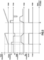
- the figure 3 represents an example of several parameters of opening of the hinge 10 as a function of time obtained via the detection unit 12.
- the hinge 10 has been opened at time t1 and closed at time t2; it has been opened at a maximum aperture angle ⁇ 1; it was opened in all for a period T1; and it was opened faster than it was closed (V1> V2 in absolute value).
- V1> V2 in absolute value we also see that the hinge 10 has been re-opened at time t3, at a maximum opening angle ⁇ 2, and that a few times later the opening angle has been reduced to a value ⁇ 3 very low without however completely close the hinge 10 (or the leaf mounted on the hinge 10).
Landscapes
- Engineering & Computer Science (AREA)
- Mechanical Engineering (AREA)
- Arrangements For Transmission Of Measured Signals (AREA)
- Telephone Set Structure (AREA)
Applications Claiming Priority (1)
| Application Number | Priority Date | Filing Date | Title |
|---|---|---|---|
| FR1554796A FR3036723B1 (fr) | 2015-05-28 | 2015-05-28 | Charniere equipee d'une unite de detection |
Publications (2)
| Publication Number | Publication Date |
|---|---|
| EP3098375A1 true EP3098375A1 (de) | 2016-11-30 |
| EP3098375B1 EP3098375B1 (de) | 2019-12-18 |
Family
ID=53541821
Family Applications (1)
| Application Number | Title | Priority Date | Filing Date |
|---|---|---|---|
| EP16171509.9A Active EP3098375B1 (de) | 2015-05-28 | 2016-05-26 | Scharnier, das mit einer detektionseinheit ausgestattet ist |
Country Status (2)
| Country | Link |
|---|---|
| EP (1) | EP3098375B1 (de) |
| FR (1) | FR3036723B1 (de) |
Citations (3)
| Publication number | Priority date | Publication date | Assignee | Title |
|---|---|---|---|---|
| US20060181108A1 (en) * | 2003-09-29 | 2006-08-17 | Cleland Terry P | Low-mounted powered opening system and control mechanism |
| DE102005059538A1 (de) * | 2005-12-13 | 2007-06-14 | Asm Automation Sensorik Messtechnik Gmbh | Scharnier-Sensor |
| DE102010017007A1 (de) * | 2010-05-18 | 2011-11-24 | Haps Gmbh + Co. Kg | Scharnier mit Bewegungssensor |
-
2015
- 2015-05-28 FR FR1554796A patent/FR3036723B1/fr not_active Expired - Fee Related
-
2016
- 2016-05-26 EP EP16171509.9A patent/EP3098375B1/de active Active
Patent Citations (3)
| Publication number | Priority date | Publication date | Assignee | Title |
|---|---|---|---|---|
| US20060181108A1 (en) * | 2003-09-29 | 2006-08-17 | Cleland Terry P | Low-mounted powered opening system and control mechanism |
| DE102005059538A1 (de) * | 2005-12-13 | 2007-06-14 | Asm Automation Sensorik Messtechnik Gmbh | Scharnier-Sensor |
| DE102010017007A1 (de) * | 2010-05-18 | 2011-11-24 | Haps Gmbh + Co. Kg | Scharnier mit Bewegungssensor |
Also Published As
| Publication number | Publication date |
|---|---|
| EP3098375B1 (de) | 2019-12-18 |
| FR3036723B1 (fr) | 2018-03-02 |
| FR3036723A1 (fr) | 2016-12-02 |
Similar Documents
| Publication | Publication Date | Title |
|---|---|---|
| EP2487452B1 (de) | Instrument zur Messung von Abmessungen mit Schnittstelle, und entsprechende Schnittstelle | |
| CA2943691C (fr) | Organe de mesure de pression etanche | |
| FR3071794B1 (fr) | Balai d'essuie-glace | |
| WO2019081834A1 (fr) | Capteur de couple pour élément en rotation utilisant un couplage mécanique à friction | |
| EP3626632A1 (de) | Sammel- und analyseverfahren von daten eines luftfahrzeugs | |
| FR2715729A1 (fr) | Dispositif d'indication de couple. | |
| EP3098375B1 (de) | Scharnier, das mit einer detektionseinheit ausgestattet ist | |
| FR3055235B1 (fr) | Dispositif de vissage a mesure de couple de sortie optimisee, et procede de determination du couple de sortie correspondant | |
| EP3885514B1 (de) | Elektromechanische vorrichtung zur betätigung eines schlosses mit lösung des federriegels beim öffnen des öffnungsflügels für eine vorgegebene zeit | |
| EP3994804B1 (de) | Verfahren zur bestimmung mindestens eines ortes für den empfang eines rückgestreuten umgebungssignals | |
| FR3070067A1 (fr) | Dispositif autonome connecte de detection et de mesure d'un deplacement non autorise d'un objet et procede correspondant | |
| WO2014013160A1 (fr) | Dispositif de mesure d'un couple transmis par un arbre de transmission de puissance avec prise en compte des variations de température | |
| EP3987671A1 (de) | Verfahren zur bestimmung mindestens eines ortes für die rückstreuung eines umgebungssignals | |
| FR3037206A1 (fr) | Systeme et procede d'enregistrement video pour partie de peche | |
| EP3835730B1 (de) | Technik zur übertragung einer messung durch einen sensor | |
| FR3084155A1 (fr) | Capteur omnidirectionnel pour la determination d’une valeur environnementale d’un objet pivotant | |
| EP0580520B1 (de) | Verfahren und Vorrichtung zum Anpassen von elektronischen Systemen an Wasserzähler | |
| FR2954506A1 (fr) | Dispositif, procede et systeme d'acquisition d'une mesure realisee par un compteur electrique | |
| EP0162990A1 (de) | Einwegmesskopf und Fernmessgerät mit einem solchen Kopf | |
| EP3767059B1 (de) | Positionsdetektor eines zapfens für einen rahmen eines kippfensters, und detektionsverfahren | |
| EP3035145B1 (de) | Anlage zur aufrollsteuerung eines anzeigebildschirms | |
| FR3144673A1 (fr) | Jumelles électroniques | |
| EP4276778A1 (de) | Aktivitätszähler, bestehend aus einem elektronischen modul mit magnetischer befestigung an einem fahrzeug | |
| FR3017458A1 (fr) | Dispositif de mesure de couple pour arbre de turbomachine. | |
| WO2025158113A1 (fr) | Dispositif de détection d'une position d'un obturateur d'une ouverture |
Legal Events
| Date | Code | Title | Description |
|---|---|---|---|
| PUAI | Public reference made under article 153(3) epc to a published international application that has entered the european phase |
Free format text: ORIGINAL CODE: 0009012 |
|
| AK | Designated contracting states |
Kind code of ref document: A1 Designated state(s): AL AT BE BG CH CY CZ DE DK EE ES FI FR GB GR HR HU IE IS IT LI LT LU LV MC MK MT NL NO PL PT RO RS SE SI SK SM TR |
|
| AX | Request for extension of the european patent |
Extension state: BA ME |
|
| STAA | Information on the status of an ep patent application or granted ep patent |
Free format text: STATUS: REQUEST FOR EXAMINATION WAS MADE |
|
| 17P | Request for examination filed |
Effective date: 20170519 |
|
| RBV | Designated contracting states (corrected) |
Designated state(s): AL AT BE BG CH CY CZ DE DK EE ES FI FR GB GR HR HU IE IS IT LI LT LU LV MC MK MT NL NO PL PT RO RS SE SI SK SM TR |
|
| GRAP | Despatch of communication of intention to grant a patent |
Free format text: ORIGINAL CODE: EPIDOSNIGR1 |
|
| STAA | Information on the status of an ep patent application or granted ep patent |
Free format text: STATUS: GRANT OF PATENT IS INTENDED |
|
| INTG | Intention to grant announced |
Effective date: 20190711 |
|
| GRAS | Grant fee paid |
Free format text: ORIGINAL CODE: EPIDOSNIGR3 |
|
| GRAA | (expected) grant |
Free format text: ORIGINAL CODE: 0009210 |
|
| STAA | Information on the status of an ep patent application or granted ep patent |
Free format text: STATUS: THE PATENT HAS BEEN GRANTED |
|
| AK | Designated contracting states |
Kind code of ref document: B1 Designated state(s): AL AT BE BG CH CY CZ DE DK EE ES FI FR GB GR HR HU IE IS IT LI LT LU LV MC MK MT NL NO PL PT RO RS SE SI SK SM TR |
|
| REG | Reference to a national code |
Ref country code: CH Ref legal event code: EP |
|
| REG | Reference to a national code |
Ref country code: IE Ref legal event code: FG4D Free format text: LANGUAGE OF EP DOCUMENT: FRENCH |
|
| REG | Reference to a national code |
Ref country code: DE Ref legal event code: R096 Ref document number: 602016026258 Country of ref document: DE |
|
| REG | Reference to a national code |
Ref country code: AT Ref legal event code: REF Ref document number: 1214767 Country of ref document: AT Kind code of ref document: T Effective date: 20200115 |
|
| REG | Reference to a national code |
Ref country code: NL Ref legal event code: MP Effective date: 20191218 |
|
| PG25 | Lapsed in a contracting state [announced via postgrant information from national office to epo] |
Ref country code: FI Free format text: LAPSE BECAUSE OF FAILURE TO SUBMIT A TRANSLATION OF THE DESCRIPTION OR TO PAY THE FEE WITHIN THE PRESCRIBED TIME-LIMIT Effective date: 20191218 Ref country code: GR Free format text: LAPSE BECAUSE OF FAILURE TO SUBMIT A TRANSLATION OF THE DESCRIPTION OR TO PAY THE FEE WITHIN THE PRESCRIBED TIME-LIMIT Effective date: 20200319 Ref country code: NO Free format text: LAPSE BECAUSE OF FAILURE TO SUBMIT A TRANSLATION OF THE DESCRIPTION OR TO PAY THE FEE WITHIN THE PRESCRIBED TIME-LIMIT Effective date: 20200318 Ref country code: LT Free format text: LAPSE BECAUSE OF FAILURE TO SUBMIT A TRANSLATION OF THE DESCRIPTION OR TO PAY THE FEE WITHIN THE PRESCRIBED TIME-LIMIT Effective date: 20191218 Ref country code: LV Free format text: LAPSE BECAUSE OF FAILURE TO SUBMIT A TRANSLATION OF THE DESCRIPTION OR TO PAY THE FEE WITHIN THE PRESCRIBED TIME-LIMIT Effective date: 20191218 Ref country code: SE Free format text: LAPSE BECAUSE OF FAILURE TO SUBMIT A TRANSLATION OF THE DESCRIPTION OR TO PAY THE FEE WITHIN THE PRESCRIBED TIME-LIMIT Effective date: 20191218 Ref country code: BG Free format text: LAPSE BECAUSE OF FAILURE TO SUBMIT A TRANSLATION OF THE DESCRIPTION OR TO PAY THE FEE WITHIN THE PRESCRIBED TIME-LIMIT Effective date: 20200318 |
|
| REG | Reference to a national code |
Ref country code: LT Ref legal event code: MG4D |
|
| PG25 | Lapsed in a contracting state [announced via postgrant information from national office to epo] |
Ref country code: HR Free format text: LAPSE BECAUSE OF FAILURE TO SUBMIT A TRANSLATION OF THE DESCRIPTION OR TO PAY THE FEE WITHIN THE PRESCRIBED TIME-LIMIT Effective date: 20191218 Ref country code: RS Free format text: LAPSE BECAUSE OF FAILURE TO SUBMIT A TRANSLATION OF THE DESCRIPTION OR TO PAY THE FEE WITHIN THE PRESCRIBED TIME-LIMIT Effective date: 20191218 |
|
| PG25 | Lapsed in a contracting state [announced via postgrant information from national office to epo] |
Ref country code: AL Free format text: LAPSE BECAUSE OF FAILURE TO SUBMIT A TRANSLATION OF THE DESCRIPTION OR TO PAY THE FEE WITHIN THE PRESCRIBED TIME-LIMIT Effective date: 20191218 |
|
| PG25 | Lapsed in a contracting state [announced via postgrant information from national office to epo] |
Ref country code: NL Free format text: LAPSE BECAUSE OF FAILURE TO SUBMIT A TRANSLATION OF THE DESCRIPTION OR TO PAY THE FEE WITHIN THE PRESCRIBED TIME-LIMIT Effective date: 20191218 Ref country code: EE Free format text: LAPSE BECAUSE OF FAILURE TO SUBMIT A TRANSLATION OF THE DESCRIPTION OR TO PAY THE FEE WITHIN THE PRESCRIBED TIME-LIMIT Effective date: 20191218 Ref country code: CZ Free format text: LAPSE BECAUSE OF FAILURE TO SUBMIT A TRANSLATION OF THE DESCRIPTION OR TO PAY THE FEE WITHIN THE PRESCRIBED TIME-LIMIT Effective date: 20191218 Ref country code: RO Free format text: LAPSE BECAUSE OF FAILURE TO SUBMIT A TRANSLATION OF THE DESCRIPTION OR TO PAY THE FEE WITHIN THE PRESCRIBED TIME-LIMIT Effective date: 20191218 Ref country code: PT Free format text: LAPSE BECAUSE OF FAILURE TO SUBMIT A TRANSLATION OF THE DESCRIPTION OR TO PAY THE FEE WITHIN THE PRESCRIBED TIME-LIMIT Effective date: 20200513 |
|
| PG25 | Lapsed in a contracting state [announced via postgrant information from national office to epo] |
Ref country code: SM Free format text: LAPSE BECAUSE OF FAILURE TO SUBMIT A TRANSLATION OF THE DESCRIPTION OR TO PAY THE FEE WITHIN THE PRESCRIBED TIME-LIMIT Effective date: 20191218 Ref country code: IS Free format text: LAPSE BECAUSE OF FAILURE TO SUBMIT A TRANSLATION OF THE DESCRIPTION OR TO PAY THE FEE WITHIN THE PRESCRIBED TIME-LIMIT Effective date: 20200418 Ref country code: SK Free format text: LAPSE BECAUSE OF FAILURE TO SUBMIT A TRANSLATION OF THE DESCRIPTION OR TO PAY THE FEE WITHIN THE PRESCRIBED TIME-LIMIT Effective date: 20191218 |
|
| REG | Reference to a national code |
Ref country code: DE Ref legal event code: R097 Ref document number: 602016026258 Country of ref document: DE |
|
| REG | Reference to a national code |
Ref country code: AT Ref legal event code: MK05 Ref document number: 1214767 Country of ref document: AT Kind code of ref document: T Effective date: 20191218 |
|
| PLBE | No opposition filed within time limit |
Free format text: ORIGINAL CODE: 0009261 |
|
| STAA | Information on the status of an ep patent application or granted ep patent |
Free format text: STATUS: NO OPPOSITION FILED WITHIN TIME LIMIT |
|
| PG25 | Lapsed in a contracting state [announced via postgrant information from national office to epo] |
Ref country code: ES Free format text: LAPSE BECAUSE OF FAILURE TO SUBMIT A TRANSLATION OF THE DESCRIPTION OR TO PAY THE FEE WITHIN THE PRESCRIBED TIME-LIMIT Effective date: 20191218 Ref country code: DK Free format text: LAPSE BECAUSE OF FAILURE TO SUBMIT A TRANSLATION OF THE DESCRIPTION OR TO PAY THE FEE WITHIN THE PRESCRIBED TIME-LIMIT Effective date: 20191218 |
|
| 26N | No opposition filed |
Effective date: 20200921 |
|
| PG25 | Lapsed in a contracting state [announced via postgrant information from national office to epo] |
Ref country code: SI Free format text: LAPSE BECAUSE OF FAILURE TO SUBMIT A TRANSLATION OF THE DESCRIPTION OR TO PAY THE FEE WITHIN THE PRESCRIBED TIME-LIMIT Effective date: 20191218 Ref country code: AT Free format text: LAPSE BECAUSE OF FAILURE TO SUBMIT A TRANSLATION OF THE DESCRIPTION OR TO PAY THE FEE WITHIN THE PRESCRIBED TIME-LIMIT Effective date: 20191218 |
|
| PG25 | Lapsed in a contracting state [announced via postgrant information from national office to epo] |
Ref country code: MC Free format text: LAPSE BECAUSE OF FAILURE TO SUBMIT A TRANSLATION OF THE DESCRIPTION OR TO PAY THE FEE WITHIN THE PRESCRIBED TIME-LIMIT Effective date: 20191218 Ref country code: IT Free format text: LAPSE BECAUSE OF FAILURE TO SUBMIT A TRANSLATION OF THE DESCRIPTION OR TO PAY THE FEE WITHIN THE PRESCRIBED TIME-LIMIT Effective date: 20191218 Ref country code: LI Free format text: LAPSE BECAUSE OF NON-PAYMENT OF DUE FEES Effective date: 20200531 Ref country code: CH Free format text: LAPSE BECAUSE OF NON-PAYMENT OF DUE FEES Effective date: 20200531 |
|
| PG25 | Lapsed in a contracting state [announced via postgrant information from national office to epo] |
Ref country code: PL Free format text: LAPSE BECAUSE OF FAILURE TO SUBMIT A TRANSLATION OF THE DESCRIPTION OR TO PAY THE FEE WITHIN THE PRESCRIBED TIME-LIMIT Effective date: 20191218 |
|
| REG | Reference to a national code |
Ref country code: BE Ref legal event code: MM Effective date: 20200531 |
|
| PG25 | Lapsed in a contracting state [announced via postgrant information from national office to epo] |
Ref country code: LU Free format text: LAPSE BECAUSE OF NON-PAYMENT OF DUE FEES Effective date: 20200526 |
|
| PG25 | Lapsed in a contracting state [announced via postgrant information from national office to epo] |
Ref country code: IE Free format text: LAPSE BECAUSE OF NON-PAYMENT OF DUE FEES Effective date: 20200526 |
|
| PG25 | Lapsed in a contracting state [announced via postgrant information from national office to epo] |
Ref country code: BE Free format text: LAPSE BECAUSE OF NON-PAYMENT OF DUE FEES Effective date: 20200531 |
|
| PG25 | Lapsed in a contracting state [announced via postgrant information from national office to epo] |
Ref country code: TR Free format text: LAPSE BECAUSE OF FAILURE TO SUBMIT A TRANSLATION OF THE DESCRIPTION OR TO PAY THE FEE WITHIN THE PRESCRIBED TIME-LIMIT Effective date: 20191218 Ref country code: MT Free format text: LAPSE BECAUSE OF FAILURE TO SUBMIT A TRANSLATION OF THE DESCRIPTION OR TO PAY THE FEE WITHIN THE PRESCRIBED TIME-LIMIT Effective date: 20191218 Ref country code: CY Free format text: LAPSE BECAUSE OF FAILURE TO SUBMIT A TRANSLATION OF THE DESCRIPTION OR TO PAY THE FEE WITHIN THE PRESCRIBED TIME-LIMIT Effective date: 20191218 |
|
| PG25 | Lapsed in a contracting state [announced via postgrant information from national office to epo] |
Ref country code: MK Free format text: LAPSE BECAUSE OF FAILURE TO SUBMIT A TRANSLATION OF THE DESCRIPTION OR TO PAY THE FEE WITHIN THE PRESCRIBED TIME-LIMIT Effective date: 20191218 |
|
| REG | Reference to a national code |
Ref country code: DE Ref legal event code: R082 Ref document number: 602016026258 Country of ref document: DE Representative=s name: CBDL PATENTANWAELTE GBR, DE Ref country code: DE Ref legal event code: R082 Ref document number: 602016026258 Country of ref document: DE Representative=s name: CBDL PATENTANWAELTE EGBR, DE |
|
| PGFP | Annual fee paid to national office [announced via postgrant information from national office to epo] |
Ref country code: DE Payment date: 20250513 Year of fee payment: 10 |
|
| PGFP | Annual fee paid to national office [announced via postgrant information from national office to epo] |
Ref country code: GB Payment date: 20250521 Year of fee payment: 10 |
|
| PGFP | Annual fee paid to national office [announced via postgrant information from national office to epo] |
Ref country code: FR Payment date: 20250520 Year of fee payment: 10 |