EP3098403A1 - Vorrichtung zur steuerung der zufuhr einer unter druck stehenden flüssigkeit - Google Patents
Vorrichtung zur steuerung der zufuhr einer unter druck stehenden flüssigkeit Download PDFInfo
- Publication number
- EP3098403A1 EP3098403A1 EP15305811.0A EP15305811A EP3098403A1 EP 3098403 A1 EP3098403 A1 EP 3098403A1 EP 15305811 A EP15305811 A EP 15305811A EP 3098403 A1 EP3098403 A1 EP 3098403A1
- Authority
- EP
- European Patent Office
- Prior art keywords
- groove
- housing
- longitudinal axis
- piston
- bore
- Prior art date
- Legal status (The legal status is an assumption and is not a legal conclusion. Google has not performed a legal analysis and makes no representation as to the accuracy of the status listed.)
- Granted
Links
Images

Classifications
-
- F—MECHANICAL ENGINEERING; LIGHTING; HEATING; WEAPONS; BLASTING
- F01—MACHINES OR ENGINES IN GENERAL; ENGINE PLANTS IN GENERAL; STEAM ENGINES
- F01M—LUBRICATING OF MACHINES OR ENGINES IN GENERAL; LUBRICATING INTERNAL COMBUSTION ENGINES; CRANKCASE VENTILATING
- F01M1/00—Pressure lubrication
- F01M1/16—Controlling lubricant pressure or quantity
-
- F—MECHANICAL ENGINEERING; LIGHTING; HEATING; WEAPONS; BLASTING
- F16—ENGINEERING ELEMENTS AND UNITS; GENERAL MEASURES FOR PRODUCING AND MAINTAINING EFFECTIVE FUNCTIONING OF MACHINES OR INSTALLATIONS; THERMAL INSULATION IN GENERAL
- F16K—VALVES; TAPS; COCKS; ACTUATING-FLOATS; DEVICES FOR VENTING OR AERATING
- F16K31/00—Actuating devices; Operating means; Releasing devices
- F16K31/02—Actuating devices; Operating means; Releasing devices electric; magnetic
- F16K31/06—Actuating devices; Operating means; Releasing devices electric; magnetic using a magnet, e.g. diaphragm valves, cutting off by means of a liquid
- F16K31/0644—One-way valve
- F16K31/0668—Sliding valves
-
- F—MECHANICAL ENGINEERING; LIGHTING; HEATING; WEAPONS; BLASTING
- F16—ENGINEERING ELEMENTS AND UNITS; GENERAL MEASURES FOR PRODUCING AND MAINTAINING EFFECTIVE FUNCTIONING OF MACHINES OR INSTALLATIONS; THERMAL INSULATION IN GENERAL
- F16K—VALVES; TAPS; COCKS; ACTUATING-FLOATS; DEVICES FOR VENTING OR AERATING
- F16K31/00—Actuating devices; Operating means; Releasing devices
- F16K31/02—Actuating devices; Operating means; Releasing devices electric; magnetic
- F16K31/06—Actuating devices; Operating means; Releasing devices electric; magnetic using a magnet, e.g. diaphragm valves, cutting off by means of a liquid
- F16K31/0686—Braking, pressure equilibration, shock absorbing
-
- F—MECHANICAL ENGINEERING; LIGHTING; HEATING; WEAPONS; BLASTING
- F01—MACHINES OR ENGINES IN GENERAL; ENGINE PLANTS IN GENERAL; STEAM ENGINES
- F01L—CYCLICALLY OPERATING VALVES FOR MACHINES OR ENGINES
- F01L1/00—Valve-gear or valve arrangements, e.g. lift-valve gear
- F01L1/34—Valve-gear or valve arrangements, e.g. lift-valve gear characterised by the provision of means for changing the timing of the valves without changing the duration of opening and without affecting the magnitude of the valve lift
- F01L1/344—Valve-gear or valve arrangements, e.g. lift-valve gear characterised by the provision of means for changing the timing of the valves without changing the duration of opening and without affecting the magnitude of the valve lift changing the angular relationship between crankshaft and camshaft, e.g. using helicoidal gear
- F01L1/3442—Valve-gear or valve arrangements, e.g. lift-valve gear characterised by the provision of means for changing the timing of the valves without changing the duration of opening and without affecting the magnitude of the valve lift changing the angular relationship between crankshaft and camshaft, e.g. using helicoidal gear using hydraulic chambers with variable volume to transmit the rotating force
-
- F—MECHANICAL ENGINEERING; LIGHTING; HEATING; WEAPONS; BLASTING
- F01—MACHINES OR ENGINES IN GENERAL; ENGINE PLANTS IN GENERAL; STEAM ENGINES
- F01L—CYCLICALLY OPERATING VALVES FOR MACHINES OR ENGINES
- F01L1/00—Valve-gear or valve arrangements, e.g. lift-valve gear
- F01L1/34—Valve-gear or valve arrangements, e.g. lift-valve gear characterised by the provision of means for changing the timing of the valves without changing the duration of opening and without affecting the magnitude of the valve lift
- F01L1/344—Valve-gear or valve arrangements, e.g. lift-valve gear characterised by the provision of means for changing the timing of the valves without changing the duration of opening and without affecting the magnitude of the valve lift changing the angular relationship between crankshaft and camshaft, e.g. using helicoidal gear
- F01L1/3442—Valve-gear or valve arrangements, e.g. lift-valve gear characterised by the provision of means for changing the timing of the valves without changing the duration of opening and without affecting the magnitude of the valve lift changing the angular relationship between crankshaft and camshaft, e.g. using helicoidal gear using hydraulic chambers with variable volume to transmit the rotating force
- F01L2001/34423—Details relating to the hydraulic feeding circuit
- F01L2001/34426—Oil control valves
-
- F—MECHANICAL ENGINEERING; LIGHTING; HEATING; WEAPONS; BLASTING
- F01—MACHINES OR ENGINES IN GENERAL; ENGINE PLANTS IN GENERAL; STEAM ENGINES
- F01L—CYCLICALLY OPERATING VALVES FOR MACHINES OR ENGINES
- F01L1/00—Valve-gear or valve arrangements, e.g. lift-valve gear
- F01L1/34—Valve-gear or valve arrangements, e.g. lift-valve gear characterised by the provision of means for changing the timing of the valves without changing the duration of opening and without affecting the magnitude of the valve lift
- F01L1/344—Valve-gear or valve arrangements, e.g. lift-valve gear characterised by the provision of means for changing the timing of the valves without changing the duration of opening and without affecting the magnitude of the valve lift changing the angular relationship between crankshaft and camshaft, e.g. using helicoidal gear
- F01L1/3442—Valve-gear or valve arrangements, e.g. lift-valve gear characterised by the provision of means for changing the timing of the valves without changing the duration of opening and without affecting the magnitude of the valve lift changing the angular relationship between crankshaft and camshaft, e.g. using helicoidal gear using hydraulic chambers with variable volume to transmit the rotating force
- F01L2001/34423—Details relating to the hydraulic feeding circuit
- F01L2001/34426—Oil control valves
- F01L2001/3443—Solenoid driven oil control valves
Definitions
- the present invention relates to a device for controlling the supply of a system with a fluid under pressure, for example a control device for regulating the oil pressure in a heat engine.
- a hydraulic valve makes it possible to transfer a fluid from one lane to another lane when the fluid reaches a pressure threshold, the so-called opening pressure.
- the valve is disposed between a fluid supply path under pressure and a fluid discharge path to the system to be fed. It comprises a valve body comprising a bore, a piston or shutter mounted to slide tightly or substantially sealingly in the bore of the valve body, a valve seat against which the piston rests in the closed position of the valve, and a spring which recalls the piston against the valve seat.
- the opening pressure level of the valve is determined by the return force of the spring.
- the valve seat is disposed between the fluid supply path and the fluid transfer path. When the piston is detached from the valve seat, the two channels are in communication otherwise they are isolated from one another.
- the force of the return spring is a function of the section of the piston that sees the hydraulic pressure.
- a spring of great stiffness, so having a high restoring force, may therefore be necessary.
- the two channels are put in communication, for example by means of a magnetic core displaced by the supply of a coil and not by the direct action of the pressure on the piston. It may be interesting to have a distributor who is to some extent directly sensitive to this pressure.
- a fluid supply control device comprising a body, a moving assembly of which at least one part is slidable in the body, the body comprising at least a first lateral supply port. pressurized fluid and at least a first lateral orifice for evacuating the pressurized fluid, return means for closing the moving equipment, the mobile equipment comprising a groove of the moving equipment in its lateral surface in permanent communication with the first lateral supply port.
- An element is movably mounted in a housing of the moving element and is fixed relative to the body of the device in a direction opposite to the direction of movement of the moving element towards a state of communication of the supply and discharge orifices, the housing being in permanent communication with the groove to bring the fluid into contact with the element.
- the device is a valve and the movable element comprises a piston only. Thanks to the invention, reduced force return means can be implemented because the force to which they are intended to oppose is reduced since it is proportional to the active surface of the element. So by choosing an element having a low active surface the force applied by the pressure on the piston is reduced. The spring can then be reduced in size.
- a dispenser comprising actuating means for communicating or not the supply port and the discharge orifice independently of the pressure, for example electromagnetic means , which makes it possible to realize a solenoid valve which offers a direct sensitivity to the pressure of the fluid.
- actuating means for communicating or not the supply port and the discharge orifice independently of the pressure, for example electromagnetic means , which makes it possible to realize a solenoid valve which offers a direct sensitivity to the pressure of the fluid.
- This direct sensitivity makes it possible for example to make dispensers safer, since they can make it possible to let a fluid under pressure even in the event of failure of the actuating means.
- the subject of the present invention is therefore a device for controlling the supply of pressurized fluid
- a body comprising a bore of longitudinal axis, a movable assembly capable of sliding in the bore, at least one feed orifice made in the body and disposed laterally with respect to the longitudinal axis, at least one discharge orifice formed in the body laterally with respect to the longitudinal axis, the movable element being able to slide between at least one first interruption position communication between the supply port and the discharge port and a second position of communication between the supply port and the discharge port, means of return of the mobile equipment to the first position, the movable element comprising a lateral surface intended to cooperate with the bore in a sealed or substantially watertight manner, at least one groove in the lateral surface of the mobile equipment, said groove being in permanent communication with the supply port, the mobile assembly comprising at least one housing extending parallel to the longitudinal axis and a member slidably mounted in said housing, said housing being in communication permanent with said groove so that an end of said element is in contact
- the mobile assembly may comprise a plurality of housings in permanent communication with the said groove and an element sliding in each housing, so that an end of said elements is in contact with the fluid under pressure and in which the elements are fixed relative to the body at least in a direction opposite to the direction of movement of the moving element of the first position to the second position.
- the housing of the moving element is for example coaxial with the longitudinal axis of the body.
- the moving element is a piston comprising the groove and at least one longitudinal through bore in which the element is slidably mounted, and in which the second end of the element is in mechanical abutment against a bottom. from the body.
- the present invention also relates to a distributor comprising a control device according to the invention and external actuating means adapted to move the movable element in the open position independently of the pressure level in the groove.
- the actuating means may advantageously comprise a magnetic core and a solenoid adapted to move the magnetic core along the longitudinal axis.
- the movable element may comprise a dispensing spool comprising the groove and the magnetic core integral with the dispensing spool.
- the movable element comprises a pusher between the dispensing spool and the magnetic core.
- the housing may be formed in the magnetic core and the dispensing spool and the pusher may include a feed passage of the pressurized fluid to the housing in the pusher.
- the present invention also relates to a hydraulic system comprising a control device according to the invention or a distributor according to the invention.
- the present invention also relates to a hydraulic pump comprising a control device according to the invention or a distributor according to the invention.
- the present invention also relates to a propulsion system of a motor vehicle comprising a heat engine and a pump according to the invention.
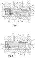
- the hydraulic valve 2 can be mounted directly on the casing of a heat engine block or in an oil pump casing 1 of a heat engine for the regulation of the oil pressure in a heat engine or the regulation of the pressure of any fluid.
- the valve 2 comprises a body 4 intended to be mounted for example in a crankcase, a piston 6 or shutter and a return means 8 reminding the piston 6 in the closed position of the valve.
- the body has a longitudinal axis X and has a bore 10 of longitudinal axis X, in which is slidably mounted substantially piston 6, at least one lateral supply port 14 and at least one lateral discharge port 16, the two lateral orifices 14 and 16 opening into the bore 10 and being arranged at different longitudinal positions along the axis X.
- the lateral supply port 14 is intended to be connected to a source of pressurized fluid and the lateral discharge port 16 is intended to be connected to a system for supplying fluid.
- the body has two diametrically opposite supply ports 14 and two diametrically opposite discharge ports 16.
- the bore is closed at an upstream longitudinal end by a bottom 18 against which is intended to bear an upstream longitudinal end 6.1 of the piston.
- Upstream and downstream are considered in relation to the direction of movement of the piston for the opening of the valve, this direction being symbolized by the arrow F.
- the return means 8 which is in the example shown formed by a helical compression spring, is mounted in reaction between a longitudinal downstream end 20 of the bore, opposite the bottom 18, and a downstream longitudinal end 6.2 of the opposite piston. at the upstream longitudinal end 6.1 of the piston.
- the spring 8 bears against a piece 22 fixed in the bore.
- the valve comprises a vent 24 formed at the longitudinal end downstream of the bore 10 and the piston 6 has a longitudinal passage extending over its entire length and opening into its upstream and downstream ends and communicating with the vent 24.
- the piston has in its outer lateral surface an annular groove 26 which, in a closed state of the valve ( figure 1 ), is located at the right of the feed opening 14.
- the groove 26 is delimited longitudinally by an upstream end 28 and a downstream end 30.
- the groove 26 has a "stepped" shape simplifying its production method.
- the groove bottom diameter could be the same over the entire length of the groove.
- the groove 26 has a certain axial extension so that, in the closed state, its downstream end is upstream of the discharge opening, and in the open state, its upstream end is at the right of the opening of supply and its downstream end is at the right of the discharge opening and communicates the supply opening 14 and the discharge opening 16.
- the piston 6 comprises a housing 32 extending parallel to the longitudinal axis and opening into the upstream end of the groove 26 and into the longitudinal end upstream of the piston, and a member 34 mounted to be movable in translation in the bore of substantially watertight manner.
- the element 34 is in permanent abutment against the bottom of the bore.
- pressurized fluid entering through the feed orifice 14 into the groove 26 applies a pressure on the walls of the groove and on a downstream longitudinal end 36 of the element 34.
- the surfaces on which the pressure of the fluid is applied are equal to the projected surfaces of the walls of the groove on a plane perpendicular to the longitudinal axis.
- the fluid from the supply source enters the groove 26 via the supply port 14, its pressure is applied to the upstream ends 28 and downstream 30 of the groove 26. Due to the presence of the housing and of the element 34 which is movable relative to the piston 6 and abuts against the bottom of the bore 4, the surface of the groove on which the pressure is exerted in the downstream direction and greater than that on which the pressure s' exerted in the upstream direction and the resulting surface is equal to the surface of the downstream end 36 of the element 34. There is therefore a driving force which is exerted on the piston in the direction of the opening of the valve.
- the pressure of the fluid ensuring the opening of the valve depends on the feedback applied by the return means and the resulting surface.
- the piston moves according to the arrow F, the downstream end of the groove 26 arrives at the right or the discharge orifices 16 and puts in communication the power source and the system to feed ( figure 2 ). Communication between the system and the vent is interrupted.
- the spring load can be very low because it depends on the resulting surface on which the fluid pressure will be exerted, which corresponds to the cross section of the element 34, which can be low. Therefore, at given opening pressure, the valve according to the invention implements a spring having a lower load than the valves of the state of the art, which makes it possible to use smaller springs and thus to gain in size.
- valve is of simplified embodiment because the bore of the body has a single diameter and the piston has a single outer diameter, unlike the valves of the state of the art in which the bore of the body has at least two diameters to form a valve seat against which the piston bears to close the valve.
- the movable elements could have different cross sections.
- the element 34 is independent of the body of the valve and abuts against it.
- it can be considered that it is integral with the bottom of the bore, or that it is made in one piece with the bottom.
- the longitudinal end of the element is substantially flush with the upstream end of the groove 26, but it could be provided that it is recessed with respect to the upstream end, ie the element would have a shorter length. to that of the bore, or projecting from the upstream end, ie the element would have a length greater than that of the bore.
- the diameter of the piston could have a diameter of 10 mm, and the diameter of the element 34 could be between 0.5 mm and 3 mm.
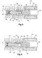
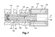
- FIG. 5 to 7 an example of a slide valve whose position is controlled by external actuating means can be seen. It can be a solenoid valve.
- the solenoid valves of the state of the art comprise a shutter, a magnetic core moved by a magnetic field produced by a coil fed with electric current causes the displacement of the shutter and therefore the communication between a fluid source and a system to be powered.
- the opening of the solenoid valve is controlled only by the supply of the coil and in no case directly by the pressure on the shutter.
- the solenoid valve according to the invention has on the contrary a certain sensitivity to the pressure of the fluid applying to the shutter.
- the solenoid valve comprises a body 104 and a piston or drawer 106 similar to the body 4 and the piston 6 of the valve of the figure 1 respectively.
- a return means 108 is provided between the body and the piston to return the piston to the closed position of the piston.
- the body 104 has a bore 110 of longitudinal axis X, in which is slidably mounted to slide the slide valve 106. It comprises at least one lateral feed orifice 114 and at least one lateral discharge orifice 116, the two orifices lateral 114 and 116 opening into the bore 110 and being arranged at different longitudinal positions along the axis X.
- the lateral supply port 114 is intended to be connected to a source of pressurized fluid and the lateral discharge port 116 is intended to be connected to a system for supplying fluid.
- the body 104 has two diametrically opposite supply ports 114 and two diametrically opposite discharge ports 116.
- the bore 110 is closed at an upstream longitudinal end by a core 138 which will be described below.
- the return means 108 which is in the example shown formed by a helical compression spring, is mounted in reaction between a downstream longitudinal end 120 of the bore opposite to the bottom 118 and a downstream longitudinal end 106.2 of the opposite drawer to the first longitudinal end 106.1 of the drawer.
- the spring bears against a piece 122 fixed in the bore.
- the valve comprises a vent 124 formed at the second longitudinal end of the bore 110 and the spool 106 has a longitudinal passage extending over its entire length and opening into its upstream and downstream ends and communicating with the vent 124.
- the drawer has in its outer lateral surface an annular groove 126, which in a closed state of the valve ( figure 5 ) is located at the right of the feed opening 114.
- the groove 126 is delimited longitudinally by an upstream end 128 and a downstream end 130.
- the groove 126 has a certain axial extension so that, in the closed state, its downstream end is upstream of the discharge opening 116, and in the open state, its upstream end is at the right of the opening. 114 and its downstream end is at the right of the discharge opening 116 and communicates the feed opening 114 and the discharge opening 116.
- the spool 106 comprises a housing 132 extending parallel to the longitudinal axis, opening into the upstream end of the groove 126 and into the upstream longitudinal end of the spool, and a member 134 mounted to be movable in translation in the bore of substantially watertight manner.
- the element 134 is in permanent abutment against a magnetic sleeve 146 fixed with respect to the body 104.
- the pressurized fluid entering through the feed orifice 114 into the groove 126 applies a pressure on the walls of the groove and on a downstream longitudinal end 136 of the element 134 which is on the side of the groove.
- the surfaces on which the pressure of the fluid is applied are equal to the projected surfaces of the walls of the groove on a plane perpendicular to the longitudinal axis.
- the solenoid valve comprises actuating means 137 for controlling the flow of fluid between the supply port 114 and the discharge port 116.
- the actuating means 137 comprise a core 138 mounted to move in a solenoid 140 connected to a source of electric current, the solenoid being integrated in a magnetic loop 142 to guide the magnetic field and a pusher 144 disposed between the magnetic core and the upstream longitudinal end of the spool 106, so that the displacement of the core 138 in the direction of the arrow F applies a thrust force to the spool 106 in the opening direction of the solenoid valve .
- the solenoid 140 is for example a copper winding.
- the magnetic sleeve 146 is fixed in the body 104 and is assembled between the slide 106 and the core 138, the latter is sealed in the body 104 and is traversed by the pusher 144.
- the drawer 106, the magnetic core 138 and the pusher 144 can be integral in translation and form a moving assembly
- the actuating means can be of any type, for example mechanical, piezoelectric ...
- the pressurized fluid fills the groove and applies force to the upstream and downstream ends of the groove.
- the flapper Figures 1 and 2 the presence of the element bearing on the sleeve 146 which is fixed relative to the body, the surface of the downstream end of the groove is larger than the upstream end of the groove. This active surface generates a force proportional to the pressure opposite to the load of the return spring which causes the displacement of the spool 106.
- the spool 106 moves sufficiently to put in communication the orifices 114 and 116.
- the communication between the system and the vent is interrupted ( figure 6 ).
- the displacement of the magnetic core 138 may be all or nothing or proportional to the current supplying the solenoid.
- the pressure of the fluid necessary to enable the communication of the orifices 114 and 116 without activation of actuating means is chosen to be greater than the fluid pressure for which the actuating means are programmed to bring the orifices 114 and 116 into communication.
- the sensitivity of the solenoid valve to the pressure ensures a safety function in case of failure of the solenoid valve.
- valve As for the valve, several elements 134 could be mounted in the drawer.
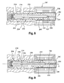
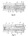
- the pusher 244 and the slide are in one piece and the pusher 244 is fitted into the movable core 238, the assembly forms a mobile assembly designated 206 and slidably mounted in the magnetic sleeve 246. .
- the movable core 238 has a through passage 232 coaxial with the longitudinal axis X and in which is mounted the element 234.
- the mounting of the element 234 in the passage 232 is such that the element can slide relative to the core and sufficient sealing is achieved.
- a piece 252 closes the passage 232 on the side of its upstream end which forms an axial stop for the element 234.
- the slide has a passage 250 extending between the groove 226 and the through passage 232 of the core 238 downstream of the element 234 to allow the pressurized fluid to contact the downstream face 236 of the element 234.
- the magnetic core 238 can bathe in the engine oil.
- means for sealingly isolating the core of the fluid are provided.
- the upstream end of the piston is axially secured to the magnetic core 238, it is for example forced into it.
- the central passage 232 comprises a shoulder 254 located downstream of the element 234 and forming an axial stop for the element 234 in the downstream direction.
- the passage 250 could have any shape since it only serves to bring the fluid under pressure into contact with the element 234.
- the distributor therefore changes state without activation of the control means.
- the moving equipment moves from upstream to downstream.
- the orifice 214 and the discharge port 216 are placed in communication and the communication between the discharge port 216 and the vent is interrupted ( figure 10 ).
- This variant has the advantage of being of simple construction.
- the length of the pusher which is integral with the slide 206, is such that the element 234 slides directly into the passage 250 longitudinally traversing the slide.
- the passage 250 extends longitudinally along the axis X, but it could be expected that only the portion of the passage 250 housing the element 234 is rectilinear to allow its sliding.
- the dispenser is in an open state, the actuating means being activated or not.
- This variant has the advantage of being of simple construction.
- the dispenser according to the invention can very advantageously be implemented in any system for regulating a pressure of a fluid, for example in an oil pump of a heat engine for regulating the oil pressure in the engine.
- the invention it is possible to provide control devices for the fluid supply under pressure of simplified structure because the bore of the body may comprise a single diameter and the outer surface may comprise a single diameter.
Landscapes
- Engineering & Computer Science (AREA)
- General Engineering & Computer Science (AREA)
- Mechanical Engineering (AREA)
- Magnetically Actuated Valves (AREA)
Priority Applications (3)
| Application Number | Priority Date | Filing Date | Title |
|---|---|---|---|
| ES15305811T ES2770048T3 (es) | 2015-05-28 | 2015-05-28 | Dispositivo de control de una alimentación de fluido a presión |
| PT153058110T PT3098403T (pt) | 2015-05-28 | 2015-05-28 | Dispositivo de comando de uma alimentação de fluido sob pressão |
| EP15305811.0A EP3098403B1 (de) | 2015-05-28 | 2015-05-28 | Vorrichtung zur steuerung der zufuhr einer unter druck stehenden flüssigkeit |
Applications Claiming Priority (1)
| Application Number | Priority Date | Filing Date | Title |
|---|---|---|---|
| EP15305811.0A EP3098403B1 (de) | 2015-05-28 | 2015-05-28 | Vorrichtung zur steuerung der zufuhr einer unter druck stehenden flüssigkeit |
Publications (2)
| Publication Number | Publication Date |
|---|---|
| EP3098403A1 true EP3098403A1 (de) | 2016-11-30 |
| EP3098403B1 EP3098403B1 (de) | 2019-11-06 |
Family
ID=53442692
Family Applications (1)
| Application Number | Title | Priority Date | Filing Date |
|---|---|---|---|
| EP15305811.0A Active EP3098403B1 (de) | 2015-05-28 | 2015-05-28 | Vorrichtung zur steuerung der zufuhr einer unter druck stehenden flüssigkeit |
Country Status (3)
| Country | Link |
|---|---|
| EP (1) | EP3098403B1 (de) |
| ES (1) | ES2770048T3 (de) |
| PT (1) | PT3098403T (de) |
Cited By (2)
| Publication number | Priority date | Publication date | Assignee | Title |
|---|---|---|---|---|
| WO2020030802A1 (fr) * | 2018-08-10 | 2020-02-13 | Bontaz Centre R & D | Electrovanne on/off offrant 2 niveaux de regulation mecanique de la pression |
| CN114934921A (zh) * | 2022-01-12 | 2022-08-23 | 威海威农科技发展有限公司 | 一种后补偿式可调流量分配阀 |
Families Citing this family (1)
| Publication number | Priority date | Publication date | Assignee | Title |
|---|---|---|---|---|
| DE102017001318B4 (de) | 2017-02-11 | 2022-02-24 | Thomas Magnete Gmbh | Druckregelventil für eine Verstellpumpe |
Citations (5)
| Publication number | Priority date | Publication date | Assignee | Title |
|---|---|---|---|---|
| JPH01261581A (ja) * | 1988-04-08 | 1989-10-18 | Kayaba Ind Co Ltd | 制御バルブ |
| US5571248A (en) * | 1995-03-10 | 1996-11-05 | General Motors Corporation | Pressure regulator |
| US5876185A (en) * | 1996-11-20 | 1999-03-02 | Caterpillar Inc. | Load sensing pump control for a variable displacement pump |
| US5894860A (en) * | 1997-06-12 | 1999-04-20 | General Motors Corporation | Proportional pressure control solenoid valve |
| DE19949234A1 (de) * | 1999-10-13 | 2001-06-07 | Hydac Electronic Gmbh | Ventil, insbesondere Druckregelventil |
-
2015
- 2015-05-28 PT PT153058110T patent/PT3098403T/pt unknown
- 2015-05-28 ES ES15305811T patent/ES2770048T3/es active Active
- 2015-05-28 EP EP15305811.0A patent/EP3098403B1/de active Active
Patent Citations (5)
| Publication number | Priority date | Publication date | Assignee | Title |
|---|---|---|---|---|
| JPH01261581A (ja) * | 1988-04-08 | 1989-10-18 | Kayaba Ind Co Ltd | 制御バルブ |
| US5571248A (en) * | 1995-03-10 | 1996-11-05 | General Motors Corporation | Pressure regulator |
| US5876185A (en) * | 1996-11-20 | 1999-03-02 | Caterpillar Inc. | Load sensing pump control for a variable displacement pump |
| US5894860A (en) * | 1997-06-12 | 1999-04-20 | General Motors Corporation | Proportional pressure control solenoid valve |
| DE19949234A1 (de) * | 1999-10-13 | 2001-06-07 | Hydac Electronic Gmbh | Ventil, insbesondere Druckregelventil |
Cited By (4)
| Publication number | Priority date | Publication date | Assignee | Title |
|---|---|---|---|---|
| WO2020030802A1 (fr) * | 2018-08-10 | 2020-02-13 | Bontaz Centre R & D | Electrovanne on/off offrant 2 niveaux de regulation mecanique de la pression |
| FR3084922A1 (fr) * | 2018-08-10 | 2020-02-14 | Bontaz Centre R & D | Electrovanne on/off offrant 2 niveaux de regulation mecanique de la pression |
| US11879555B2 (en) | 2018-08-10 | 2024-01-23 | Bontaz Centre | On/off solenoid valve providing two levels of mechanical pressure regulation |
| CN114934921A (zh) * | 2022-01-12 | 2022-08-23 | 威海威农科技发展有限公司 | 一种后补偿式可调流量分配阀 |
Also Published As
| Publication number | Publication date |
|---|---|
| EP3098403B1 (de) | 2019-11-06 |
| ES2770048T3 (es) | 2020-06-30 |
| PT3098403T (pt) | 2020-01-29 |
Similar Documents
| Publication | Publication Date | Title |
|---|---|---|
| EP2326811B1 (de) | Vorrichtung zur steuerung der fluidversorgung eines systems | |
| EP2778364B1 (de) | Steuervorrichtung der Einspeisung einer Flüssigkeit in ein System | |
| CA2774320C (fr) | Doseur de carburant ayant un dispositif de regulation ameliore | |
| WO2017064438A1 (fr) | Vanne fluidique a hysteresis | |
| FR2954447A1 (fr) | Electrovanne et installation d'assistance de conduite equipee d'au moins une telle electrovanne | |
| EP3098403B1 (de) | Vorrichtung zur steuerung der zufuhr einer unter druck stehenden flüssigkeit | |
| EP3026310B1 (de) | Elektromagnetisches Ventil für kryogenes Hochdruckgas | |
| WO2016097546A1 (fr) | Electrovanne comprenant deux circuits fluidiques independants et etanches, commandes par un actionneur electromagnetique unique, et moteur comprenant une telle electrovanne | |
| FR2956716A1 (fr) | Soupape electromagnetique pour commander un fluide | |
| FR2767932A1 (fr) | Dispositif de regulation de debit volumique et systeme d'injection comportant un tel dispositif de regulation, notamment pour moteur a combustion interne | |
| WO2017046509A1 (fr) | Agencement et méthode pour réguler un flux de gaz de carter d'un moteur à combustion interne avant une séparation d'huile | |
| FR2955170A1 (fr) | Robinet de gaz et bouteille de gaz sous pression comportant un tel robinet | |
| FR2893379A1 (fr) | Vanne coaxiale d'interception destinee a etre utilisee dans des installations d'air comprime | |
| EP3831676B1 (de) | Vorrichtung zur betätigung eines schienenfahrzeug-bremssystems und mit einer solchen betätigungsvorrichtung ausgestattetes schienenfahrzeug | |
| FR2552514A1 (fr) | Amortisseur du type fluidique | |
| FR2933161A1 (fr) | Valve hydraulique | |
| EP3477415B1 (de) | Thermostatventil | |
| EP2005047A1 (de) | Druckregelmagnetventil | |
| FR3022317A1 (fr) | Vanne a trois voies comportant un noyau en translation | |
| WO2017072081A1 (fr) | Injecteur de carburant | |
| WO2021245509A1 (fr) | Vanne hydropneumatique comportant un module de précédence | |
| EP2384942B1 (de) | Hydraulisches Bremssystem mit einem verbesserten Steuerglied | |
| EP3821158A1 (de) | Ein-/aus-magnetventil mit zwei stufen der mechanischen druckregelung | |
| FR2872243A1 (fr) | Electrovanne munie d'un dispositif de liaison couplant l'induit a son element de soupape | |
| FR2834026A1 (fr) | Systeme de pilotage de l'ouverture/fermeture d'un embrayage par module de robotisation |
Legal Events
| Date | Code | Title | Description |
|---|---|---|---|
| PUAI | Public reference made under article 153(3) epc to a published international application that has entered the european phase |
Free format text: ORIGINAL CODE: 0009012 |
|
| AK | Designated contracting states |
Kind code of ref document: A1 Designated state(s): AL AT BE BG CH CY CZ DE DK EE ES FI FR GB GR HR HU IE IS IT LI LT LU LV MC MK MT NL NO PL PT RO RS SE SI SK SM TR |
|
| AX | Request for extension of the european patent |
Extension state: BA ME |
|
| STAA | Information on the status of an ep patent application or granted ep patent |
Free format text: STATUS: REQUEST FOR EXAMINATION WAS MADE |
|
| 17P | Request for examination filed |
Effective date: 20170519 |
|
| RBV | Designated contracting states (corrected) |
Designated state(s): AL AT BE BG CH CY CZ DE DK EE ES FI FR GB GR HR HU IE IS IT LI LT LU LV MC MK MT NL NO PL PT RO RS SE SI SK SM TR |
|
| GRAP | Despatch of communication of intention to grant a patent |
Free format text: ORIGINAL CODE: EPIDOSNIGR1 |
|
| RIC1 | Information provided on ipc code assigned before grant |
Ipc: F01M 1/16 20060101AFI20190415BHEP Ipc: F15B 13/04 20060101ALI20190415BHEP Ipc: F01L 1/344 20060101ALI20190415BHEP Ipc: F16K 31/06 20060101ALI20190415BHEP |
|
| STAA | Information on the status of an ep patent application or granted ep patent |
Free format text: STATUS: GRANT OF PATENT IS INTENDED |
|
| INTG | Intention to grant announced |
Effective date: 20190523 |
|
| GRAS | Grant fee paid |
Free format text: ORIGINAL CODE: EPIDOSNIGR3 |
|
| GRAA | (expected) grant |
Free format text: ORIGINAL CODE: 0009210 |
|
| STAA | Information on the status of an ep patent application or granted ep patent |
Free format text: STATUS: THE PATENT HAS BEEN GRANTED |
|
| AK | Designated contracting states |
Kind code of ref document: B1 Designated state(s): AL AT BE BG CH CY CZ DE DK EE ES FI FR GB GR HR HU IE IS IT LI LT LU LV MC MK MT NL NO PL PT RO RS SE SI SK SM TR |
|
| REG | Reference to a national code |
Ref country code: GB Ref legal event code: FG4D Free format text: NOT ENGLISH |
|
| REG | Reference to a national code |
Ref country code: CH Ref legal event code: EP Ref country code: AT Ref legal event code: REF Ref document number: 1198992 Country of ref document: AT Kind code of ref document: T Effective date: 20191115 |
|
| REG | Reference to a national code |
Ref country code: IE Ref legal event code: FG4D Free format text: LANGUAGE OF EP DOCUMENT: FRENCH |
|
| REG | Reference to a national code |
Ref country code: DE Ref legal event code: R096 Ref document number: 602015041061 Country of ref document: DE |
|
| REG | Reference to a national code |
Ref country code: PT Ref legal event code: SC4A Ref document number: 3098403 Country of ref document: PT Date of ref document: 20200129 Kind code of ref document: T Free format text: AVAILABILITY OF NATIONAL TRANSLATION Effective date: 20200120 |
|
| REG | Reference to a national code |
Ref country code: SE Ref legal event code: TRGR |
|
| REG | Reference to a national code |
Ref country code: NL Ref legal event code: MP Effective date: 20191106 |
|
| REG | Reference to a national code |
Ref country code: LT Ref legal event code: MG4D |
|
| PG25 | Lapsed in a contracting state [announced via postgrant information from national office to epo] |
Ref country code: BG Free format text: LAPSE BECAUSE OF FAILURE TO SUBMIT A TRANSLATION OF THE DESCRIPTION OR TO PAY THE FEE WITHIN THE PRESCRIBED TIME-LIMIT Effective date: 20200206 Ref country code: FI Free format text: LAPSE BECAUSE OF FAILURE TO SUBMIT A TRANSLATION OF THE DESCRIPTION OR TO PAY THE FEE WITHIN THE PRESCRIBED TIME-LIMIT Effective date: 20191106 Ref country code: NL Free format text: LAPSE BECAUSE OF FAILURE TO SUBMIT A TRANSLATION OF THE DESCRIPTION OR TO PAY THE FEE WITHIN THE PRESCRIBED TIME-LIMIT Effective date: 20191106 Ref country code: LV Free format text: LAPSE BECAUSE OF FAILURE TO SUBMIT A TRANSLATION OF THE DESCRIPTION OR TO PAY THE FEE WITHIN THE PRESCRIBED TIME-LIMIT Effective date: 20191106 Ref country code: GR Free format text: LAPSE BECAUSE OF FAILURE TO SUBMIT A TRANSLATION OF THE DESCRIPTION OR TO PAY THE FEE WITHIN THE PRESCRIBED TIME-LIMIT Effective date: 20200207 Ref country code: NO Free format text: LAPSE BECAUSE OF FAILURE TO SUBMIT A TRANSLATION OF THE DESCRIPTION OR TO PAY THE FEE WITHIN THE PRESCRIBED TIME-LIMIT Effective date: 20200206 Ref country code: PL Free format text: LAPSE BECAUSE OF FAILURE TO SUBMIT A TRANSLATION OF THE DESCRIPTION OR TO PAY THE FEE WITHIN THE PRESCRIBED TIME-LIMIT Effective date: 20191106 Ref country code: LT Free format text: LAPSE BECAUSE OF FAILURE TO SUBMIT A TRANSLATION OF THE DESCRIPTION OR TO PAY THE FEE WITHIN THE PRESCRIBED TIME-LIMIT Effective date: 20191106 |
|
| PG25 | Lapsed in a contracting state [announced via postgrant information from national office to epo] |
Ref country code: HR Free format text: LAPSE BECAUSE OF FAILURE TO SUBMIT A TRANSLATION OF THE DESCRIPTION OR TO PAY THE FEE WITHIN THE PRESCRIBED TIME-LIMIT Effective date: 20191106 Ref country code: IS Free format text: LAPSE BECAUSE OF FAILURE TO SUBMIT A TRANSLATION OF THE DESCRIPTION OR TO PAY THE FEE WITHIN THE PRESCRIBED TIME-LIMIT Effective date: 20200306 Ref country code: RS Free format text: LAPSE BECAUSE OF FAILURE TO SUBMIT A TRANSLATION OF THE DESCRIPTION OR TO PAY THE FEE WITHIN THE PRESCRIBED TIME-LIMIT Effective date: 20191106 |
|
| PG25 | Lapsed in a contracting state [announced via postgrant information from national office to epo] |
Ref country code: AL Free format text: LAPSE BECAUSE OF FAILURE TO SUBMIT A TRANSLATION OF THE DESCRIPTION OR TO PAY THE FEE WITHIN THE PRESCRIBED TIME-LIMIT Effective date: 20191106 |
|
| REG | Reference to a national code |
Ref country code: ES Ref legal event code: FG2A Ref document number: 2770048 Country of ref document: ES Kind code of ref document: T3 Effective date: 20200630 |
|
| PG25 | Lapsed in a contracting state [announced via postgrant information from national office to epo] |
Ref country code: DK Free format text: LAPSE BECAUSE OF FAILURE TO SUBMIT A TRANSLATION OF THE DESCRIPTION OR TO PAY THE FEE WITHIN THE PRESCRIBED TIME-LIMIT Effective date: 20191106 Ref country code: EE Free format text: LAPSE BECAUSE OF FAILURE TO SUBMIT A TRANSLATION OF THE DESCRIPTION OR TO PAY THE FEE WITHIN THE PRESCRIBED TIME-LIMIT Effective date: 20191106 Ref country code: RO Free format text: LAPSE BECAUSE OF FAILURE TO SUBMIT A TRANSLATION OF THE DESCRIPTION OR TO PAY THE FEE WITHIN THE PRESCRIBED TIME-LIMIT Effective date: 20191106 |
|
| REG | Reference to a national code |
Ref country code: DE Ref legal event code: R097 Ref document number: 602015041061 Country of ref document: DE |
|
| REG | Reference to a national code |
Ref country code: AT Ref legal event code: MK05 Ref document number: 1198992 Country of ref document: AT Kind code of ref document: T Effective date: 20191106 |
|
| PG25 | Lapsed in a contracting state [announced via postgrant information from national office to epo] |
Ref country code: SK Free format text: LAPSE BECAUSE OF FAILURE TO SUBMIT A TRANSLATION OF THE DESCRIPTION OR TO PAY THE FEE WITHIN THE PRESCRIBED TIME-LIMIT Effective date: 20191106 Ref country code: SM Free format text: LAPSE BECAUSE OF FAILURE TO SUBMIT A TRANSLATION OF THE DESCRIPTION OR TO PAY THE FEE WITHIN THE PRESCRIBED TIME-LIMIT Effective date: 20191106 |
|
| PLBE | No opposition filed within time limit |
Free format text: ORIGINAL CODE: 0009261 |
|
| STAA | Information on the status of an ep patent application or granted ep patent |
Free format text: STATUS: NO OPPOSITION FILED WITHIN TIME LIMIT |
|
| 26N | No opposition filed |
Effective date: 20200807 |
|
| PG25 | Lapsed in a contracting state [announced via postgrant information from national office to epo] |
Ref country code: SI Free format text: LAPSE BECAUSE OF FAILURE TO SUBMIT A TRANSLATION OF THE DESCRIPTION OR TO PAY THE FEE WITHIN THE PRESCRIBED TIME-LIMIT Effective date: 20191106 Ref country code: AT Free format text: LAPSE BECAUSE OF FAILURE TO SUBMIT A TRANSLATION OF THE DESCRIPTION OR TO PAY THE FEE WITHIN THE PRESCRIBED TIME-LIMIT Effective date: 20191106 |
|
| PG25 | Lapsed in a contracting state [announced via postgrant information from national office to epo] |
Ref country code: LI Free format text: LAPSE BECAUSE OF NON-PAYMENT OF DUE FEES Effective date: 20200531 Ref country code: MC Free format text: LAPSE BECAUSE OF FAILURE TO SUBMIT A TRANSLATION OF THE DESCRIPTION OR TO PAY THE FEE WITHIN THE PRESCRIBED TIME-LIMIT Effective date: 20191106 Ref country code: CH Free format text: LAPSE BECAUSE OF NON-PAYMENT OF DUE FEES Effective date: 20200531 |
|
| REG | Reference to a national code |
Ref country code: BE Ref legal event code: MM Effective date: 20200531 |
|
| PG25 | Lapsed in a contracting state [announced via postgrant information from national office to epo] |
Ref country code: LU Free format text: LAPSE BECAUSE OF NON-PAYMENT OF DUE FEES Effective date: 20200528 |
|
| PG25 | Lapsed in a contracting state [announced via postgrant information from national office to epo] |
Ref country code: IE Free format text: LAPSE BECAUSE OF NON-PAYMENT OF DUE FEES Effective date: 20200528 |
|
| PG25 | Lapsed in a contracting state [announced via postgrant information from national office to epo] |
Ref country code: BE Free format text: LAPSE BECAUSE OF NON-PAYMENT OF DUE FEES Effective date: 20200531 |
|
| PG25 | Lapsed in a contracting state [announced via postgrant information from national office to epo] |
Ref country code: TR Free format text: LAPSE BECAUSE OF FAILURE TO SUBMIT A TRANSLATION OF THE DESCRIPTION OR TO PAY THE FEE WITHIN THE PRESCRIBED TIME-LIMIT Effective date: 20191106 Ref country code: MT Free format text: LAPSE BECAUSE OF FAILURE TO SUBMIT A TRANSLATION OF THE DESCRIPTION OR TO PAY THE FEE WITHIN THE PRESCRIBED TIME-LIMIT Effective date: 20191106 Ref country code: CY Free format text: LAPSE BECAUSE OF FAILURE TO SUBMIT A TRANSLATION OF THE DESCRIPTION OR TO PAY THE FEE WITHIN THE PRESCRIBED TIME-LIMIT Effective date: 20191106 |
|
| PG25 | Lapsed in a contracting state [announced via postgrant information from national office to epo] |
Ref country code: MK Free format text: LAPSE BECAUSE OF FAILURE TO SUBMIT A TRANSLATION OF THE DESCRIPTION OR TO PAY THE FEE WITHIN THE PRESCRIBED TIME-LIMIT Effective date: 20191106 |
|
| REG | Reference to a national code |
Ref country code: GB Ref legal event code: 732E Free format text: REGISTERED BETWEEN 20230302 AND 20230308 |
|
| REG | Reference to a national code |
Ref country code: DE Ref legal event code: R081 Ref document number: 602015041061 Country of ref document: DE Owner name: BONTAZ CENTRE, FR Free format text: FORMER OWNER: BONTAZ CENTRE R&D, MARNAZ, FR |
|
| REG | Reference to a national code |
Ref country code: ES Ref legal event code: PC2A Owner name: BONTAZ CENTRE Effective date: 20230620 |
|
| PGFP | Annual fee paid to national office [announced via postgrant information from national office to epo] |
Ref country code: DE Payment date: 20250529 Year of fee payment: 11 |
|
| PGFP | Annual fee paid to national office [announced via postgrant information from national office to epo] |
Ref country code: ES Payment date: 20250611 Year of fee payment: 11 |
|
| PGFP | Annual fee paid to national office [announced via postgrant information from national office to epo] |
Ref country code: IT Payment date: 20250529 Year of fee payment: 11 |
|
| PGFP | Annual fee paid to national office [announced via postgrant information from national office to epo] |
Ref country code: PT Payment date: 20250521 Year of fee payment: 11 |
|
| PGFP | Annual fee paid to national office [announced via postgrant information from national office to epo] |
Ref country code: FR Payment date: 20250530 Year of fee payment: 11 |
|
| PGFP | Annual fee paid to national office [announced via postgrant information from national office to epo] |
Ref country code: CZ Payment date: 20250522 Year of fee payment: 11 |
|
| PGFP | Annual fee paid to national office [announced via postgrant information from national office to epo] |
Ref country code: SE Payment date: 20250530 Year of fee payment: 11 |
|
| PGFP | Annual fee paid to national office [announced via postgrant information from national office to epo] |
Ref country code: GB Payment date: 20260327 Year of fee payment: 12 |