EP3098448A1 - Verfahren und regelkreis zur regelung eines elektrischen antriebs eines elektrisch angetriebenen druckluftverdichters eines kraftfahrzeugs - Google Patents
Verfahren und regelkreis zur regelung eines elektrischen antriebs eines elektrisch angetriebenen druckluftverdichters eines kraftfahrzeugs Download PDFInfo
- Publication number
- EP3098448A1 EP3098448A1 EP16000917.1A EP16000917A EP3098448A1 EP 3098448 A1 EP3098448 A1 EP 3098448A1 EP 16000917 A EP16000917 A EP 16000917A EP 3098448 A1 EP3098448 A1 EP 3098448A1
- Authority
- EP
- European Patent Office
- Prior art keywords
- air compressor
- electric drive
- control
- compressed air
- drive shaft
- Prior art date
- Legal status (The legal status is an assumption and is not a legal conclusion. Google has not performed a legal analysis and makes no representation as to the accuracy of the status listed.)
- Granted
Links
Images
Classifications
-
- B—PERFORMING OPERATIONS; TRANSPORTING
- B60—VEHICLES IN GENERAL
- B60T—VEHICLE BRAKE CONTROL SYSTEMS OR PARTS THEREOF; BRAKE CONTROL SYSTEMS OR PARTS THEREOF, IN GENERAL; ARRANGEMENT OF BRAKING ELEMENTS ON VEHICLES IN GENERAL; PORTABLE DEVICES FOR PREVENTING UNWANTED MOVEMENT OF VEHICLES; VEHICLE MODIFICATIONS TO FACILITATE COOLING OF BRAKES
- B60T13/00—Transmitting braking action from initiating means to ultimate brake actuator with power assistance or drive; Brake systems incorporating such transmitting means, e.g. air-pressure brake systems
- B60T13/10—Transmitting braking action from initiating means to ultimate brake actuator with power assistance or drive; Brake systems incorporating such transmitting means, e.g. air-pressure brake systems with fluid assistance, drive, or release
- B60T13/24—Transmitting braking action from initiating means to ultimate brake actuator with power assistance or drive; Brake systems incorporating such transmitting means, e.g. air-pressure brake systems with fluid assistance, drive, or release the fluid being gaseous
- B60T13/26—Compressed-air systems
-
- F—MECHANICAL ENGINEERING; LIGHTING; HEATING; WEAPONS; BLASTING
- F04—POSITIVE - DISPLACEMENT MACHINES FOR LIQUIDS; PUMPS FOR LIQUIDS OR ELASTIC FLUIDS
- F04B—POSITIVE-DISPLACEMENT MACHINES FOR LIQUIDS; PUMPS
- F04B27/00—Multi-cylinder pumps specially adapted for elastic fluids and characterised by number or arrangement of cylinders
- F04B27/005—Multi-cylinder pumps specially adapted for elastic fluids and characterised by number or arrangement of cylinders with two cylinders
-
- F—MECHANICAL ENGINEERING; LIGHTING; HEATING; WEAPONS; BLASTING
- F04—POSITIVE - DISPLACEMENT MACHINES FOR LIQUIDS; PUMPS FOR LIQUIDS OR ELASTIC FLUIDS
- F04B—POSITIVE-DISPLACEMENT MACHINES FOR LIQUIDS; PUMPS
- F04B35/00—Piston pumps specially adapted for elastic fluids and characterised by the driving means to their working members, or by combination with, or adaptation to, specific driving engines or motors, not otherwise provided for
- F04B35/04—Piston pumps specially adapted for elastic fluids and characterised by the driving means to their working members, or by combination with, or adaptation to, specific driving engines or motors, not otherwise provided for the means being electric
-
- F—MECHANICAL ENGINEERING; LIGHTING; HEATING; WEAPONS; BLASTING
- F04—POSITIVE - DISPLACEMENT MACHINES FOR LIQUIDS; PUMPS FOR LIQUIDS OR ELASTIC FLUIDS
- F04B—POSITIVE-DISPLACEMENT MACHINES FOR LIQUIDS; PUMPS
- F04B49/00—Control, e.g. of pump delivery, or pump pressure of, or safety measures for, machines, pumps, or pumping installations, not otherwise provided for, or of interest apart from, groups F04B1/00 - F04B47/00
- F04B49/06—Control using electricity
-
- F—MECHANICAL ENGINEERING; LIGHTING; HEATING; WEAPONS; BLASTING
- F04—POSITIVE - DISPLACEMENT MACHINES FOR LIQUIDS; PUMPS FOR LIQUIDS OR ELASTIC FLUIDS
- F04C—ROTARY-PISTON, OR OSCILLATING-PISTON, POSITIVE-DISPLACEMENT MACHINES FOR LIQUIDS; ROTARY-PISTON, OR OSCILLATING-PISTON, POSITIVE-DISPLACEMENT PUMPS
- F04C18/00—Rotary-piston pumps specially adapted for elastic fluids
- F04C18/08—Rotary-piston pumps specially adapted for elastic fluids of intermeshing-engagement type, i.e. with engagement of co-operating members similar to that of toothed gearing
- F04C18/12—Rotary-piston pumps specially adapted for elastic fluids of intermeshing-engagement type, i.e. with engagement of co-operating members similar to that of toothed gearing of other than internal-axis type
- F04C18/14—Rotary-piston pumps specially adapted for elastic fluids of intermeshing-engagement type, i.e. with engagement of co-operating members similar to that of toothed gearing of other than internal-axis type with toothed rotary pistons
- F04C18/16—Rotary-piston pumps specially adapted for elastic fluids of intermeshing-engagement type, i.e. with engagement of co-operating members similar to that of toothed gearing of other than internal-axis type with toothed rotary pistons with helical teeth, e.g. chevron-shaped, screw type
-
- F—MECHANICAL ENGINEERING; LIGHTING; HEATING; WEAPONS; BLASTING
- F04—POSITIVE - DISPLACEMENT MACHINES FOR LIQUIDS; PUMPS FOR LIQUIDS OR ELASTIC FLUIDS
- F04C—ROTARY-PISTON, OR OSCILLATING-PISTON, POSITIVE-DISPLACEMENT MACHINES FOR LIQUIDS; ROTARY-PISTON, OR OSCILLATING-PISTON, POSITIVE-DISPLACEMENT PUMPS
- F04C18/00—Rotary-piston pumps specially adapted for elastic fluids
- F04C18/30—Rotary-piston pumps specially adapted for elastic fluids having the characteristics covered by two or more of groups F04C18/02, F04C18/08, F04C18/22, F04C18/24, F04C18/48, or having the characteristics covered by one of these groups together with some other type of movement between co-operating members
- F04C18/34—Rotary-piston pumps specially adapted for elastic fluids having the characteristics covered by two or more of groups F04C18/02, F04C18/08, F04C18/22, F04C18/24, F04C18/48, or having the characteristics covered by one of these groups together with some other type of movement between co-operating members having the movement defined in group F04C18/08 or F04C18/22 and relative reciprocation between the co-operating members
- F04C18/344—Rotary-piston pumps specially adapted for elastic fluids having the characteristics covered by two or more of groups F04C18/02, F04C18/08, F04C18/22, F04C18/24, F04C18/48, or having the characteristics covered by one of these groups together with some other type of movement between co-operating members having the movement defined in group F04C18/08 or F04C18/22 and relative reciprocation between the co-operating members with vanes reciprocating with respect to the inner member
-
- F—MECHANICAL ENGINEERING; LIGHTING; HEATING; WEAPONS; BLASTING
- F04—POSITIVE - DISPLACEMENT MACHINES FOR LIQUIDS; PUMPS FOR LIQUIDS OR ELASTIC FLUIDS
- F04C—ROTARY-PISTON, OR OSCILLATING-PISTON, POSITIVE-DISPLACEMENT MACHINES FOR LIQUIDS; ROTARY-PISTON, OR OSCILLATING-PISTON, POSITIVE-DISPLACEMENT PUMPS
- F04C28/00—Control of, monitoring of, or safety arrangements for, pumps or pumping installations specially adapted for elastic fluids
- F04C28/08—Control of, monitoring of, or safety arrangements for, pumps or pumping installations specially adapted for elastic fluids characterised by varying the rotational speed
-
- F—MECHANICAL ENGINEERING; LIGHTING; HEATING; WEAPONS; BLASTING
- F04—POSITIVE - DISPLACEMENT MACHINES FOR LIQUIDS; PUMPS FOR LIQUIDS OR ELASTIC FLUIDS
- F04C—ROTARY-PISTON, OR OSCILLATING-PISTON, POSITIVE-DISPLACEMENT MACHINES FOR LIQUIDS; ROTARY-PISTON, OR OSCILLATING-PISTON, POSITIVE-DISPLACEMENT PUMPS
- F04C29/00—Component parts, details or accessories of pumps or pumping installations, not provided for in groups F04C18/00 - F04C28/00
- F04C29/0042—Driving elements, brakes, couplings, transmissions specially adapted for pumps
- F04C29/0085—Prime movers
-
- G—PHYSICS
- G05—CONTROLLING; REGULATING
- G05D—SYSTEMS FOR CONTROLLING OR REGULATING NON-ELECTRIC VARIABLES
- G05D16/00—Control of fluid pressure
- G05D16/20—Control of fluid pressure characterised by the use of electric means
- G05D16/2006—Control of fluid pressure characterised by the use of electric means with direct action of electric energy on controlling means
- G05D16/2066—Control of fluid pressure characterised by the use of electric means with direct action of electric energy on controlling means using controlling means acting on the pressure source
-
- H—ELECTRICITY
- H02—GENERATION; CONVERSION OR DISTRIBUTION OF ELECTRIC POWER
- H02P—CONTROL OR REGULATION OF ELECTRIC MOTORS, ELECTRIC GENERATORS OR DYNAMO-ELECTRIC CONVERTERS; CONTROLLING TRANSFORMERS, REACTORS OR CHOKE COILS
- H02P23/00—Arrangements or methods for the control of AC motors characterised by a control method other than vector control
- H02P23/0004—Control strategies in general, e.g. linear type, e.g. P, PI, PID, using robust control
-
- H—ELECTRICITY
- H02—GENERATION; CONVERSION OR DISTRIBUTION OF ELECTRIC POWER
- H02P—CONTROL OR REGULATION OF ELECTRIC MOTORS, ELECTRIC GENERATORS OR DYNAMO-ELECTRIC CONVERTERS; CONTROLLING TRANSFORMERS, REACTORS OR CHOKE COILS
- H02P23/00—Arrangements or methods for the control of AC motors characterised by a control method other than vector control
- H02P23/04—Arrangements or methods for the control of AC motors characterised by a control method other than vector control specially adapted for damping motor oscillations, e.g. for reducing hunting
-
- F—MECHANICAL ENGINEERING; LIGHTING; HEATING; WEAPONS; BLASTING
- F04—POSITIVE - DISPLACEMENT MACHINES FOR LIQUIDS; PUMPS FOR LIQUIDS OR ELASTIC FLUIDS
- F04B—POSITIVE-DISPLACEMENT MACHINES FOR LIQUIDS; PUMPS
- F04B2201/00—Pump parameters
- F04B2201/12—Parameters of driving or driven means
- F04B2201/1201—Rotational speed of the axis
-
- F—MECHANICAL ENGINEERING; LIGHTING; HEATING; WEAPONS; BLASTING
- F04—POSITIVE - DISPLACEMENT MACHINES FOR LIQUIDS; PUMPS FOR LIQUIDS OR ELASTIC FLUIDS
- F04B—POSITIVE-DISPLACEMENT MACHINES FOR LIQUIDS; PUMPS
- F04B2201/00—Pump parameters
- F04B2201/12—Parameters of driving or driven means
- F04B2201/1202—Torque on the axis
-
- F—MECHANICAL ENGINEERING; LIGHTING; HEATING; WEAPONS; BLASTING
- F04—POSITIVE - DISPLACEMENT MACHINES FOR LIQUIDS; PUMPS FOR LIQUIDS OR ELASTIC FLUIDS
- F04B—POSITIVE-DISPLACEMENT MACHINES FOR LIQUIDS; PUMPS
- F04B2201/00—Pump parameters
- F04B2201/12—Parameters of driving or driven means
- F04B2201/1204—Position of a rotating inclined plate
- F04B2201/12041—Angular position
-
- F—MECHANICAL ENGINEERING; LIGHTING; HEATING; WEAPONS; BLASTING
- F04—POSITIVE - DISPLACEMENT MACHINES FOR LIQUIDS; PUMPS FOR LIQUIDS OR ELASTIC FLUIDS
- F04B—POSITIVE-DISPLACEMENT MACHINES FOR LIQUIDS; PUMPS
- F04B2203/00—Motor parameters
- F04B2203/02—Motor parameters of rotating electric motors
- F04B2203/0201—Current
-
- F—MECHANICAL ENGINEERING; LIGHTING; HEATING; WEAPONS; BLASTING
- F04—POSITIVE - DISPLACEMENT MACHINES FOR LIQUIDS; PUMPS FOR LIQUIDS OR ELASTIC FLUIDS
- F04B—POSITIVE-DISPLACEMENT MACHINES FOR LIQUIDS; PUMPS
- F04B2203/00—Motor parameters
- F04B2203/02—Motor parameters of rotating electric motors
- F04B2203/0207—Torque
-
- F—MECHANICAL ENGINEERING; LIGHTING; HEATING; WEAPONS; BLASTING
- F04—POSITIVE - DISPLACEMENT MACHINES FOR LIQUIDS; PUMPS FOR LIQUIDS OR ELASTIC FLUIDS
- F04B—POSITIVE-DISPLACEMENT MACHINES FOR LIQUIDS; PUMPS
- F04B2203/00—Motor parameters
- F04B2203/02—Motor parameters of rotating electric motors
- F04B2203/0209—Rotational speed
-
- F—MECHANICAL ENGINEERING; LIGHTING; HEATING; WEAPONS; BLASTING
- F04—POSITIVE - DISPLACEMENT MACHINES FOR LIQUIDS; PUMPS FOR LIQUIDS OR ELASTIC FLUIDS
- F04C—ROTARY-PISTON, OR OSCILLATING-PISTON, POSITIVE-DISPLACEMENT MACHINES FOR LIQUIDS; ROTARY-PISTON, OR OSCILLATING-PISTON, POSITIVE-DISPLACEMENT PUMPS
- F04C2240/00—Components
- F04C2240/40—Electric motor
-
- F—MECHANICAL ENGINEERING; LIGHTING; HEATING; WEAPONS; BLASTING
- F04—POSITIVE - DISPLACEMENT MACHINES FOR LIQUIDS; PUMPS FOR LIQUIDS OR ELASTIC FLUIDS
- F04C—ROTARY-PISTON, OR OSCILLATING-PISTON, POSITIVE-DISPLACEMENT MACHINES FOR LIQUIDS; ROTARY-PISTON, OR OSCILLATING-PISTON, POSITIVE-DISPLACEMENT PUMPS
- F04C2240/00—Components
- F04C2240/60—Shafts
-
- F—MECHANICAL ENGINEERING; LIGHTING; HEATING; WEAPONS; BLASTING
- F04—POSITIVE - DISPLACEMENT MACHINES FOR LIQUIDS; PUMPS FOR LIQUIDS OR ELASTIC FLUIDS
- F04C—ROTARY-PISTON, OR OSCILLATING-PISTON, POSITIVE-DISPLACEMENT MACHINES FOR LIQUIDS; ROTARY-PISTON, OR OSCILLATING-PISTON, POSITIVE-DISPLACEMENT PUMPS
- F04C2270/00—Control; Monitoring or safety arrangements
- F04C2270/03—Torque
- F04C2270/035—Controlled or regulated
-
- F—MECHANICAL ENGINEERING; LIGHTING; HEATING; WEAPONS; BLASTING
- F04—POSITIVE - DISPLACEMENT MACHINES FOR LIQUIDS; PUMPS FOR LIQUIDS OR ELASTIC FLUIDS
- F04C—ROTARY-PISTON, OR OSCILLATING-PISTON, POSITIVE-DISPLACEMENT MACHINES FOR LIQUIDS; ROTARY-PISTON, OR OSCILLATING-PISTON, POSITIVE-DISPLACEMENT PUMPS
- F04C2270/00—Control; Monitoring or safety arrangements
- F04C2270/60—Prime mover parameters
- F04C2270/605—Controlled or regulated
-
- F—MECHANICAL ENGINEERING; LIGHTING; HEATING; WEAPONS; BLASTING
- F05—INDEXING SCHEMES RELATING TO ENGINES OR PUMPS IN VARIOUS SUBCLASSES OF CLASSES F01-F04
- F05B—INDEXING SCHEME RELATING TO WIND, SPRING, WEIGHT, INERTIA OR LIKE MOTORS, TO MACHINES OR ENGINES FOR LIQUIDS COVERED BY SUBCLASSES F03B, F03D AND F03G
- F05B2210/00—Working fluid
- F05B2210/10—Kind or type
- F05B2210/12—Kind or type gaseous, i.e. compressible
-
- F—MECHANICAL ENGINEERING; LIGHTING; HEATING; WEAPONS; BLASTING
- F05—INDEXING SCHEMES RELATING TO ENGINES OR PUMPS IN VARIOUS SUBCLASSES OF CLASSES F01-F04
- F05B—INDEXING SCHEME RELATING TO WIND, SPRING, WEIGHT, INERTIA OR LIKE MOTORS, TO MACHINES OR ENGINES FOR LIQUIDS COVERED BY SUBCLASSES F03B, F03D AND F03G
- F05B2270/00—Control
- F05B2270/30—Control parameters, e.g. input parameters
- F05B2270/335—Output power or torque
-
- F—MECHANICAL ENGINEERING; LIGHTING; HEATING; WEAPONS; BLASTING
- F05—INDEXING SCHEMES RELATING TO ENGINES OR PUMPS IN VARIOUS SUBCLASSES OF CLASSES F01-F04
- F05B—INDEXING SCHEME RELATING TO WIND, SPRING, WEIGHT, INERTIA OR LIKE MOTORS, TO MACHINES OR ENGINES FOR LIQUIDS COVERED BY SUBCLASSES F03B, F03D AND F03G
- F05B2270/00—Control
- F05B2270/70—Type of control algorithm
Definitions
- the invention relates to a method for controlling an electric drive of an electrically driven air compressor of a motor vehicle.
- the invention further relates to a corresponding control circuit.
- LP compressed air compressors
- e-LP air compressors
- the electric drive of an electrically driven air compressor may comprise a frequency converter and an electric motor, wherein the electric motor may be embodied, for example, as an asynchronous machine, synchronous machine or reluctance machine.
- a method for controlling an electric drive of an electrically driven air compressor of a motor vehicle is provided.
- the motor vehicle is preferably designed as a commercial vehicle, and the compressed air compressor is preferably provided for supplying a pneumatic compressed air system, in particular a pneumatic air brake system.
- a momentary load torque of the compressed air compressor applied to a drive shaft of the air compressor driven by the electric drive is estimated as a function of at least one operating parameter and switched to the control circuit of the electric drive as a disturbance variable estimate in order to reduce a control error generated by the applied load torque. It is thus the estimated, currently applied to the drive shaft of the air compressor load torque as a function of at least one operating parameter such as disturbance estimation switched to the control circuit of the electric drive that reduces the control error generated by the load torque characteristic in the control loop, preferably minimized and thereby the dynamics the electric drive is increased.
- the feedforward torque feedforward torque control for the machine control allows to reduce the control errors, in particular for the speed and the electric current in the motor control, and to minimize peaks and fluctuations in the motor phase current or motor torque. Further advantages are the reduction of the electrical power losses and reserve in the frequency converter as well as the reduction of the mechanical load for the air compressor and motor.
- the instantaneous load torque of the compressed-air compressor applied to the drive shaft of the compressed-air compressor is estimated as a function of at least one of the following: a current angular position of the drive shaft of the compressed-air compressor; a current speed of the drive shaft of the air compressor, which is predetermined by an engine speed of the electric drive; and an instantaneous value of a pressure parameter from which a current value of an air pressure applied to the outlet port of the air compressor is derivable or can be estimated and / or which indicates a measure of a back pressure generated by a compressed air system coupled to the compressed air compressor.
- the instantaneous load torque of the compressed-air compressor applied to the drive shaft of the compressed-air compressor is estimated using at least these three operating parameters, i. H. estimated as a function of the instantaneous angular position of the drive shaft, the instantaneous speed of the drive shaft and the instantaneous value of the pressure parameter. This allows a particularly accurate estimation of the disturbance and thus a particularly strong reduction of the control error.
- the function for estimating the instantaneous load torque of the compressed-air compressor applied to the drive shaft of the air compressor can be stored as a characteristic map, for example as a matrix map, the map being determined beforehand by measuring the load torque as a function of the operating parameters.
- control circuit for an electrical current control (current control circuit) of the electric drive is subjected to the disturbance variable estimation.
- the Störashin can be inverted with the transfer function of the current control loop and added to a manipulated variable of a speed controller of the electric drive and thereby be switched to the control circuit for the electrical current control of the electric drive.
- the resulting estimated variable (disturbance variable estimate) is added via the inverse transfer function of the current control loop to a manipulated variable of the speed controller of the electric drive and thereby switched to the control circuit for the electrical current control of the electric drive.
- a particular advantage of this realization lies in the fact that the air compressor can be measured independently and the derived estimate map can be used with any electric motor and frequency converter. Thus, no further requirements are placed on the sensors of the electric motor and frequency converter with speed-controlled operation. Furthermore, the known, non-linear compressed-air compressor behavior can for the most part be relatively easily imaged and compensated. A detailed, Complex modeling of the mechanical control system from the internal structure of the air compressor is not necessary - which is much more effort on the computing power and real-time capability of the hardware and software for the control - whereby the implementation of lower additional costs for the controller with improved functionality.
- the instantaneous load torque of the compressor applied to the compressor drive shaft may be further estimated as a function of at least one of: a friction moment of the reciprocating piston, the air compressor being a reciprocating air compressor is; an ambient temperature of the air and a coolant temperature of a coolant of a cooling circuit of the air compressor.
- the compressed air compressor can be designed as Hubkolbendruck Kunststoffverêtr, for example with one or two cylinders. When working on the reciprocating principle compressed air compressors, the fluctuations in the load torque are particularly large. However, the method according to the invention is also applicable to other compressor technologies. Thus, the compressed-air compressor can also be embodied as a screw compressed-air compressor (so-called scroll principle) or as a vane-type air compressor.
- a frequency converter for controlling the electric drive is operated with a field-oriented vector control, which can be performed with and without tachometer.
- a current measurement is required for the disturbance variable connection and for the implementation of the control method or control circuit according to the invention.
- a corresponding requirement for the accuracy of the current measurement is required, but costs for the encoders or separate sensors for determining the angular position and rotational speed of the drive shaft can be saved.
- the invention is not limited to a specific structure with respect to the structural design of the electric machine of the electric drive.
- the electric machine can be designed as an asynchronous machine, synchronous machine, reluctance machine or DC machine.
- a control circuit for controlling an electric drive of an electrically driven air compressor of a motor vehicle is provided.
- the control circuit is designed to carry out the method for regulating the electric drive, as described in this document.
- the control circuit is designed to estimate a momentary load torque of the compressor applied to a drive shaft of the compressor as a function of at least one operating parameter and to apply a disturbance variable estimate to the control circuit of the electric drive in such a way that a control error generated by the applied load torque is reduced.
- the invention further relates to a motor vehicle, in particular a commercial vehicle, with an electrically driven air compressor for supplying a pneumatic compressed air / brake system and such a control loop.
- the electrically driven air compressor is exemplified as a two-cylinder Hubkolbendruck Kunststoffverêtr.
- the electric drive comprises an electric machine which drives the crankshaft (drive shaft) of the air compressor.
- the air compressor and the crankshaft which may be performed in a conventional manner are not shown.
- the principle of the control method and the control circuit is explained by the control of an electric machine designed as a DC machine.
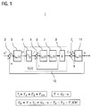
- FIG. 1 an equivalent circuit and model in the Laplace region of the control loop or the controlled system to illustrate the scheme of armature current and engine speed.
- the control loop is initially shown without the disturbance variable connection according to the invention, which is subsequently based on FIG. 2 is explained.
- FIG. 1 shows a known cascade circuit for the formation of a speed-controlled and current-controlled control loop or regulator (cascade control).
- This known control principle is used in the present case to control the electric drive of the air compressor.
- the controller can be designed, for example, as a PID, PD or PI controller.
- Nominal values are in FIG. 1 and in FIG. 2 marked with an asterisk "*".
- the cascade circuit has an external control loop, comprising the speed controller 3 and the controlled system 11 for the modeled mass moment of inertia of the air compressor, which in FIG. 1 as the transfer functions G_R ⁇ ( S ) and G _ S ⁇ ( S ) are shown.
- the speed controller 3 is acted upon by the speed control error ⁇ _ ⁇ , ie the difference formed in the differentiator 2 from the instantaneous setpoint speed ⁇ * and actually determined instantaneous speed ⁇ of the drive shaft.
- the speed controller 3 determines therefrom a manipulated variable in the form of a desired torque T *, with which the inner control circuit 10 of the cascade circuit is acted upon.
- the inner loop 10 (in FIG. 1 and FIG. 2 Also referred to as G _ T ( S )) is the electrical current control of the electric drive.
- the aim of this regulation it is known, to set a predetermined current in the machine and correct disturbances of the operating voltage.
- a subordinate current control to improve the speed control is essentially used to reduce the influence of the counter electromotive force (EMF).
- the reference numeral 8 is in FIG. 1 the transfer function ⁇ of the electromotive force (EMF) constant is designated by the reference numeral 4 corresponding to the transfer function 1 / ⁇ .
- the transfer function 1 / ⁇ calculates the setpoint current i * from the setpoint torque T *.
- the differentiator 5 calculates the current control error ⁇ _i by taking the difference between the target current i * and actually determined current i of the DC machine.
- the current controller 6, shown here as the transfer function G _ Ri ( S ), is supplied with the current control error ⁇ _ i and calculates a corresponding manipulated variable for the controlled system 7 for the Electric machine circuit, (in FIG. 1 represented as the Laplace transfer function G _ Si (S)).
- the variable T_L describes the load torque on the electric machine or the crankshaft torque of the air compressor, which represents a disturbance behavior for the control loop.
- T_L T_KW + T_ O ⁇ + T_Rest
- the first component T_KW represents by far the largest component.
- the course was in dependence on the instantaneous angular position ⁇ of the drive shaft of the air compressor, the instantaneous speed ⁇ of the drive shaft of the air compressor, which is predetermined by an engine speed of the electric drive, and the current value of a pressure parameter p , from a current value of an air pressure applied to the outlet port of the air compressor is derivable or can be estimated and / or indicates a measure of a backpressure generated by a compressed air system coupled to the compressed air compressor.
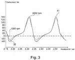
- FIG. 3 shows by way of example the course of the voltage applied to the crankshaft driven by the electric drive of a two-cylinder Hubkolbendruck Kunststoffver Whyrs load torque T_KW as a function of the angular position ⁇ of the crankshaft.
- the curve 31 with the solid line indicates the angular position-dependent curve of the load torque for a rotational speed ⁇ of 3000 revolutions per minute
- the curve 32 with the dashed line indicates the angular position-dependent curve of the load torque for a rotational speed ⁇ of 1000 revolutions per minute.
- the torque is highly dependent on the pressure build-up in the reciprocating piston or angle of the crankshaft (KW). Even with constant pressure conditions at the outlet nozzle of the air compressor, the torque changes strongly non-linearly over a full crankshaft revolution and sometimes fluctuates up to 180 Nm in the present example.
- the dynamics depend directly on the drive speed, which is exemplified by the different curves 31 and 32.
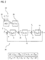
- FIG. 2 shows the development of the rule model FIG. 1 ,
- components with the same reference numerals correspond to the components of FIG. 1 and will not be described separately.
- the peculiarity of the control method according to the invention and the difference to FIG. 1 are as already mentioned above in that by means of a matrix map 21, the current load applied to the drive shaft of the air compressor load torque of the air compressor in the form of the size T ⁇ _KW is estimated.
- the instantaneous values 22 of the operating parameters ⁇ , ⁇ , p are continuously determined, and the instantaneous value for the load torque T_KW is estimated on the basis of the stored characteristic curve matrix 21 .
- the resulting estimate T ⁇ _KW is added via the inverse transfer function G -1 _ T (s) of the current control circuit 10 to a manipulated variable u of the speed controller 3 of the electric drive and thereby switched to the control circuit 10 for the electrical current control of the electric drive.
- the disturbance variable circuit is thus used to control the load applied to the electric drive.
- G_T is the transfer function of the current control loop 10
- u is the manipulated variable of the speed controller 3.
- the symbol "*" describes a multiplication in the Laplace range (no convolution).
- .DELTA.T T _ KW - T ⁇ _KW, ie corresponds to the estimation error of the crankshaft torque .
- the feedforward control of the drive shaft load torque for the engine control thus enables a reduction of the control errors, in particular for the speed and the electric current in the engine control, and a minimization of spikes and fluctuations in the motor phase current or motor torque. Further advantages are the reduction of the electrical power losses and reserve in the frequency converter as well as the reduction of the mechanical load for the air compressor and motor.
Landscapes
- Engineering & Computer Science (AREA)
- Mechanical Engineering (AREA)
- General Engineering & Computer Science (AREA)
- Power Engineering (AREA)
- Physics & Mathematics (AREA)
- Transportation (AREA)
- Fluid Mechanics (AREA)
- General Physics & Mathematics (AREA)
- Automation & Control Theory (AREA)
- Control Of Positive-Displacement Pumps (AREA)
- Control Of Electric Motors In General (AREA)
Abstract
Description
- Die Erfindung betrifft ein Verfahren zur Regelung eines elektrischen Antriebs eines elektrisch angetriebenen Druckluftverdichters eines Kraftfahrzeugs. Die Erfindung betrifft ferner einen entsprechenden Regelkreis.
- Aus der Praxis ist bekannt, Druckluftverdichter, sogenannte Luftpresser (LP), zur Versorgung pneumatischer Bremsanlagen in Nutzfahrzeugen vorzusehen, die beispielsweise nach dem Hubkolbenprinzip arbeiten. Für hybridelektrische Nutzfahrzeuge, d. h. Nutzfahrzeuge, die mit einem hybridisierten Antriebsstrang ausgestattet sind, ist es je nach Einsatzzweck erforderlich, Luftpresser vorzusehen, die zumindest teilweise elektrisch angetrieben sind, auch abgekürzt als sogenannte "e-LP" bezeichnet. Der elektrische Antrieb eines elektrisch angetriebenen Druckluftverdichters kann einen Frequenzumrichter und einen Elektromotor umfassen, wobei der Elektromotor beispielsweise als Asynchronmaschine, Synchronmaschine oder Reluktanzmaschine ausgeführt sein kann.
- Insbesondere auf der Hubkolbentechnik basierende Luftpresser weisen jedoch Lastdrehmomente mit hohen Spitzen und nichtlinearen Schwankungen auf, die der elektrische Antrieb ausgleichen muss. Selbst bei konstanten Druckverhältnissen am LP-Ausgangsstutzen ändert sich das Drehmoment stark nichtlinear über eine volle Kurbelwellenumdrehung. Dies führt zu hohen Leistungsverlusten, vor allem im Dauerbetrieb. Weitere Nachteile stellen die erforderliche hohe elektrische Leistungsreserve dar, insbesondere für den Motoranlauf des Luftpressers, sowie die hohen Kühlungsanforderungen, z. B. bei einem langsamen Motoranlauf bei hohem Drehmoment einer luftgekühlten Asynchronmaschine. Dies führt zu höherem Aufwand und Kosten in der Leistungselektronik und beim Motor, z. B. betreffend die Thermik und Stromtragfähigkeit.
- Es ist somit eine Aufgabe der Erfindung, einen verbesserten elektrischen Antrieb bzw. ein verbessertes Betriebsverfahren für einen elektrischen Antrieb eines elektrisch angetriebenen Druckluftverdichters bereitzustellen, mit dem Nachteile herkömmlicher Techniken vermieden werden können.
- Diese Aufgaben werden durch Vorrichtungen und Verfahren mit den Merkmalen der unabhängigen Ansprüche gelöst. Vorteilhafte Ausführungsformen und Anwendungen der Erfindung ergeben sich aus den abhängigen Ansprüchen und werden in der folgenden Beschreibung unter teilweiser Bezugnahme auf die Figuren näher erläutert.
- Gemäß einem ersten Gesichtspunkt der Erfindung wird ein Verfahren zur Regelung eines elektrischen Antriebs eines elektrisch angetriebenen Druckluftverdichters eines Kraftfahrzeugs bereitgestellt. Das Kraftfahrzeug ist vorzugsweise als Nutzfahrzeug ausgeführt, und der Druckluftverdichter ist vorzugsweise zur Versorgung einer pneumatischen Druckluftanlage, insbesondere einer pneumatischen Druckluftbremsanlage vorgesehen.
- Erfindungsgemäß wird ein momentanes an einer vom elektrischen Antrieb angetriebenen Antriebswelle des Druckluftverdichters anliegendes Lastdrehmoment des Druckluftverdichters als Funktion von mindestens einem Betriebsparameter geschätzt und als Störgrößenschätzung auf den Regelkreis des elektrischen Antriebs geschaltet, um einen durch das anliegende Lastdrehmoment erzeugten Regelfehler zu reduzieren. Es wird somit das geschätzte, momentan an der Antriebswelle des Druckluftverdichters anliegende Lastdrehmoment als Funktion von mindestens einem Betriebsparameter derart als Störgrößenschätzung auf den Regelkreis des elektrischen Antriebs geschaltet, dass der durch die Lastdrehmoment-Charakteristik erzeugte Regelfehler im Regelkreis reduziert, vorzugsweise minimiert und dadurch die Dynamik der elektrischen Antriebs erhöht wird.
- Die Störgrößenaufschaltung des Antriebswellenlastmoments für die Maschinenregelung ermöglicht eine Reduzierung der Regelfehler, insbesondere für die Drehzahl und den elektrischen Strom in der Motorregelung, und eine Minimierung von Spitzen und Schwankungen im Motorphasenstrom bzw. Motordrehmoment. Weitere Vorzüge liegen in der Reduzierung der elektrischen Leistungsverluste und -reserve im Frequenzumrichter sowie in der Reduzierung der mechanischen Belastung für den Druckluftverdichter und Motor.
- Gemäß einer bevorzugten Ausgestaltungsform wird das momentane an der Antriebswelle des Druckluftverdichters anliegende Lastdrehmoment des Druckluftverdichters als Funktion von zumindest einer der folgenden Größen geschätzt: einer momentanen Winkelposition der Antriebswelle des Druckluftverdichters; einer momentanen Drehzahl der Antriebswelle des Druckluftverdichters, die durch eine Motordrehzahl des elektrischen Antriebs vorgegeben ist; und einem momentanen Wert eines Druckparameters, aus dem ein aktueller Wert eines am Ausgangsstutzen des Druckluftverdichters anliegenden Luftdrucks ableitbar oder abschätzbar ist und/oder der ein Maß für einen von einer mit dem Druckluftverdichter gekoppelten Druckluftanlage erzeugten Gegendrucks angibt.
- Diese drei Betriebsparameter haben ursächlich den größten Anteil an den Schwankungen des vom Druckluftverdichter erzeugten Lastdrehmoments an der vom elektrischen Antrieb angetriebenen Antriebswelle des Druckluftverdichters und sind somit zur Schätzung des Lastdrehmoments besonders vorteilhaft.
- Gemäß einer besonders bevorzugten Ausgestaltungsform wird das momentane an der Antriebswelle des Druckluftverdichters anliegende Lastdrehmoment des Druckluftverdichters unter Verwendung zumindest dieser drei Betriebsparameter geschätzt, d. h. als Funktion der momentanen Winkelposition der Antriebswelle, der momentanen Drehzahl der Antriebswelle und des momentanen Werts des Druckparameters geschätzt. Dies ermöglicht eine besonders genaue Schätzung der Störgröße und somit eine besonders starke Reduzierung des Regelfehlers.
- Die Funktion zur Schätzung des momentanen an der Antriebswelle des Druckluftverdichters anliegenden Lastdrehmoments des Druckluftverdichters kann als Kennfeld, beispielsweise als Matrixkennfeld, hinterlegt sein, wobei das Kennfeld vorab durch Vermessung des Lastmoments in Abhängigkeit von den Betriebsparametern bestimmt wird.
- Eine Möglichkeit der erfindungsgemäßen Realisierung sieht vor, dass der Regelkreis für eine elektrische Stromregelung (Stromregelkreis) des elektrischen Antriebs mit der Störgrößenschätzung beaufschlagt wird. Insbesondere kann die Störgrößenschätzung mit der Übertragungsfunktion des Stromregelkreises invertiert werden und zu einer Stellgröße eines Drehzahlreglers des elektrischen Antriebs addiert werden und dadurch auf den Regelkreis für die elektrische Stromregelung des elektrischen Antriebs aufgeschaltet werden.
- Die resultierende Schätzgröße (Störgrößenschätzung) wird über die inverse Übertragungsfunktion des Stromregelkreises zu einer Stellgröße des Drehzahlreglers des elektrischen Antriebs addiert und dadurch auf den Regelkreis für die elektrische Stromregelung des elektrischen Antriebs aufgeschaltet.
- Ein besonderer Vorteil dieser Realisierung liegt darin, dass der Luftdruckverdichter eigenständig vermessen und das daraus abgeleitete Kennfeld für die Schätzgröße mit jedem beliebigen Elektromotor und Frequenzumrichter verwenden werden kann. Somit werden keine weiteren Anforderungen an die Sensorik von Elektromotor und Frequenzumrichter mit drehzahlregelten Betrieb gestellt. Weiterhin kann das bekannte, nichtlineare Druckluftverdichter-Verhalten größtenteils relativ einfach abgebildet und ausgeregelt werden. Eine detaillierte, aufwendige Modellierung der mechanischen Regelstrecke vom internen Aufbau des Druckluftverdichters ist nicht notwendig - was wesentlich höheren Aufwand an die Rechenleistung und Echtzeitfähigkeit der Hardware und Software für die Regelung stellt - wodurch die Implementierung geringere Mehrkosten für den Regler nach sich zieht bei verbesserter Funktionalität.
- Um die Genauigkeit der Schätzung des Lastdrehmoments weiter zu erhöhen, kann das momentane an der Antriebswelle des Verdichters anliegende Lastdrehmoment des Verdichters gemäß einer weiteren Ausführungsvariante ferner als Funktion von zumindest einer der folgenden Größen geschätzt werden: einem Reibmoment des Hubkolbens, wobei der Druckluftverdichter als Hubkolbendruckluftverdichter ausgeführt ist; einer Umgebungstemperatur der Luft und einer Kühlmitteltemperatur eines Kühlmittels eines Kühlkreislaufs des Druckluftverdichters.
- Der Druckluftverdichter kann als Hubkolbendruckluftverdichter ausgeführt sein, beispielsweise mit einem oder zwei Zylindern. Bei nach dem Hubkolben-Prinzip arbeitenden Druckluftverdichtern sind die Schwankungen im Lastmoment besonders groß. Das erfindungsgemäße Verfahren ist jedoch auch für andere Kompressortechnologien anwendbar. So kann der Druckluftverdichter auch als Schrauben-Druckluftverdichter (sog. Scroll-Prinzip) oder als Flügelzellen-Druckluftverdichter ausgeführt sein.
- Gemäß einer weiteren bevorzugten Ausführungsform wird ein Frequenzumrichter zur Regelung des elektrischen Antriebs mit einer feldorientierten Vektorregelung betrieben, welche mit und ohne Drehzahlgeber ausgeführt werden kann. Für die Störgrößenaufschaltung und zur Implementierung des erfindungsgemäßen Regelverfahrens bzw. Regelkreises ist eine Strommessung erforderlich. Zur weiteren Umsetzung einer geberlosen, feldorientierten Vektorregelung ist eine entsprechende Anforderung an die Genauigkeit der Strommessung erforderlich, es können jedoch Kosten für die Geber bzw. separaten Sensoren zur Bestimmung der Winkelposition und Drehzahl der Antriebswelle eingespart werden.
- Die Erfindung ist hinsichtlich des konstruktiven Aufbaus der elektrischen Maschine des elektrischen Antriebs nicht auf einen bestimmten Aufbau beschränkt. Die elektrische Maschine kann als Asynchronmaschine, Synchronmaschine, Reluktanzmaschine oder Gleichstrommaschine ausgeführt sein.
- Gemäß einem zweiten Gesichtspunkt der Erfindung wird ein Regelkreis zur Regelung eines elektrischen Antriebs eines elektrisch angetriebenen Druckluftverdichters eines Kraftfahrzeugs bereitgestellt. Erfindungsgemäß ist der Regelkreis ausgebildet, das Verfahren zur Regelung des elektrischen Antriebs, wie in diesem Dokument beschrieben, durchzuführen. Insbesondere ist der Regelkreis ausgeführt, ein momentanes an einer Antriebswelle des Verdichters anliegendes Lastdrehmoment des Verdichters als Funktion von wenigstens einem Betriebsparameter zu schätzen und als Störgrößenschätzung auf den Regelkreis des elektrischen Antriebs derart aufzuschalten, dass ein durch das anliegende Lastdrehmoment erzeugter Regelfehler reduziert wird. Zur Vermeidung von Wiederholungen sollen rein verfahrensgemäß offenbarte Merkmale auch als vorrichtungsgemäß offenbart gelten und beanspruchbar sein und somit auch für den Regelkreis gelten.
- Die Erfindung betrifft ferner ein Kraftfahrzeug, insbesondere ein Nutzfahrzeug, mit einem elektrisch angetriebenen Druckluftverdichter zur Versorgung einer pneumatischen Druckluft-/Bremsanlage und einem solchen Regelkreis.
- Die zuvor beschriebenen bevorzugten Ausführungsformen und Merkmale der Erfindung sind beliebig miteinander kombinierbar. Weitere Einzelheiten und Vorteile der Erfindung werden im Folgenden unter Bezug auf die beigefügten Zeichnungen beschrieben. Es zeigen:
- Figur 1
- ein Ersatzschaltbild bzw. Modell im Laplace-Bereich eines Regelkreises ohne die Störgrößenschaltung;
- Figur 2
- ein Ersatzschaltbild bzw. Modell im Laplace-Bereich eines Regelkreises mit Störgrößenschaltung gemäß einer Ausführungsform der Erfindung; und
- Figur 3
- die Kennlinien-Funktion eines Lastmoments eines Hubkolbendruckluftverdichters gemäß einer Ausführungsform der Erfindung.
- In dem beschriebenen Ausführungsbeispiel ist der elektrisch angetriebene Druckluftverdichter beispielhaft als Zweizylinder Hubkolbendruckluftverdichter ausgeführt. Der elektrische Antrieb umfasst eine elektrische Maschine, welche die Kurbelwelle (Antriebswelle) des Druckluftverdichters antreibt. Der Druckluftverdichter und die Kurbelwelle, die in an sich bekannter Weise ausgeführt sein können, sind nicht dargestellt. Das Prinzip des Regelverfahrens und des Regelkreises wird anhand der Regelung einer als Gleichstrom-Maschine ausgeführten elektrischen Maschine erklärt. Hierzu zeigt
Figur 1 ein Ersatzschaltbild und Modell im Laplace-Bereich des Regelkreises bzw. der Regelstrecke zur Illustration der Regelung von Ankerstrom und Motordrehzahl. InFigur 1 ist der Regelkreis zunächst ohne die erfindungsgemäße Störgrößenaufschaltung dargestellt, welche anschließend anhand vonFigur 2 erläutert wird. -
Figur 1 zeigt eine an sich bekannte Kaskadenschaltung zur Ausbildung eines drehzahlgeregelten und stromgeregelten Regelkreises bzw. Reglers (Kaskadenregelung). Dieses an sich bekannte Regelprinzip wird vorliegend zur Regelung des elektrischen Antriebs des Druckluftverdichters verwendet. Der Regler kann beispielsweise als PID-, PD- oder PI-Regler ausgeführt sein. - Sollgrößen sind in
Figur 1 und inFigur 2 mit einem Stern "*" gekennzeichnet. - Die Kaskadenschaltung weist einen äußeren Regelkreis auf, umfassend den Drehzahlregler 3 und die Regelstrecke 11 für das modellierte Massenträgheitsmoment des Druckluftverdichters, die in
Figur 1 als die Übertragungsfunktionen G_Rω(S) und G_Sω(S) dargestellt sind. Hierbei wird der Drehzahlregler 3 mit dem Drehzahlregelfehler ε_ω beaufschlagt, d. h. der im Differenzierer 2 gebildeten Differenz aus momentaner Solldrehzahl ω* und tatsächlich bestimmter momentaner Drehzahl ω der Antriebswelle. Der Drehzahlregler 3 bestimmt hieraus eine Stellgröße in Form eine Solldrehmoments T*, mit dem der innere Regelkreis 10 der Kaskadenschaltung beaufschlagt wird. - Der innere Regelkreis 10 (in
Figur 1 undFigur 2 auch als G_T(S) bezeichnet) dient der elektrischen Stromregelung des elektrischen Antriebs. Ziel dieser Regelung ist es bekanntermaßen, einen vorgegebenen Strom in der Maschine einzustellen und Störungen der Betriebsspannung auszuregeln. Eine unterlagerte Stromregelung zur Verbesserung der Drehzahlregelung wird im Wesentlichen verwendet, um den Einfluss der entgegengerichteten elektromotorischen Kraft (EMK) zu vermindern. Mit dem Bezugszeichen 8 ist inFigur 1 die Übertragungsfunktion ψ der Konstante für die elektromotorische Kraft (EMK) bezeichnet, mit dem Bezugszeichen 4 entsprechend die Übertragungsfunktion 1/ψ. Die Übertragungsfunktion 1/ψ berechnet aus dem Solldrehmoment T* den Sollstrom i*. - Der Differenzierer 5 berechnet den Stromregelfehler ε_i durch Bilden der Differenz aus Sollstrom i* und tatsächlich bestimmtem Strom i der Gleichstrommaschine. Der Stromregler 6, hier dargestellt als die Übertragungsfunktion G_Ri(S), wird mit dem Stromregelfehler ε_i beaufschlagt und berechnet eine entsprechende Stellgröße für die Regelstrecke 7 für den Stromkreis der elektrischen Maschine, (in
Figur 1 dargestellt als die Laplace-Übertragungsfunktion G_Si(S)). - Die Größe T_L beschreibt das Lastmoment an der elektrischen Maschine bzw. das Kurbelwellendrehmoment des Druckluftverdichters, das ein Störverhalten für den Regelkreis darstellt. Je größer die Schwankung in der Störgröße T_L, desto größer ist der Regelfehler des Regelkreises und desto stärker schwankt die Größe T_B und damit das Drehmoment, das die Regelstrecke G_Sω(S) ausgleichen muss.
- Das Lastmoment an der E-Maschine T_L bzw. das Kurbelwellendrehmoment des Druckluftverdichters besteht aus mehreren Anteilen:
- Einem ersten Anteil, der das Drehmoment T_KW = f(δ_KW, ω, p) als Funktion abhängig von der Kurbelwellenwinkelposition δ, der Drehzahl ω und dem Druck p in der Druckluftanlage angibt.
- Einem zweiten Drehmomentanteil T_Ö, der aus dem Betrieb einer Ölpumpe des Druckluftverdichters resultiert, und einem unbekanntem Restanteil T_Rest.

- Hierbei stellt der erste Anteil T_KW die weitaus größte Komponente dar.
- Das in
Figur 1 gezeigte Regelmodell wird daher weitergebildet, indem das momentane an einer Antriebswelle des Druckluftverdichters anliegende Lastdrehmoment T_L des Druckluftverdichters als Funktion von mindestens einem Betriebsparameter geschätzt wird und als Störgrößenschätzung derart auf den Regelkreis des elektrischen Antriebs geschaltet wird, dass der durch das anliegende Lastdrehmoment erzeugte Regelfehler reduziert wird. Vorliegend wird für die Störgrößenaufschaltung nur der erste Anteil T_KW geschätzt. Die Schätzgröße für T_KW wird nachfolgend mit T^_KW bezeichnet. Eine Schätzung T^_KW des Drehmoments T_KW erfolgt über ein Matrixkennfeld 21 auf Basis von Kennlinien aus vorab experimentell durchgeführten Messungen am Druckluftverdichter. - Im vorliegenden Ausführungsbeispiel wurde der Verlauf in Abhängigkeit von der momentanen Winkelposition δ der Antriebswelle des Druckluftverdichters, der momentanen Drehzahl ω der Antriebswelle des Druckluftverdichters, die durch eine Motordrehzahl des elektrischen Antriebs vorgegeben ist, und dem momentanen Wert eines Druckparameters p, aus dem ein aktueller Wert eines am Ausgangsstutzen des Druckluftverdichters anliegenden Luftdrucks ableitbar oder abschätzbar ist und/oder der ein Maß für einen von einer mit dem Druckluftverdichter gekoppelten Druckluftanlage erzeugten Gegendrucks angibt, gemessen.
-
Figur 3 zeigt beispielhaft den Verlauf des an der vom elektrischen Antrieb angetriebenen Kurbelwelle eines Zweizylinder-Hubkolbendruckluftverdichters anliegenden Lastmoments T_KW als Funktion der Winkelposition δ der Kurbelwelle. - Die Kurve 31 mit der durchgezogenen Linie gibt dabei den winkelpositionsabhängigen Verlauf des Lastdrehmoments für eine Drehzahl ω von 3000 Umdrehungen pro Minute an, während die Kurve 32 mit der strichgepunkteten Linie den winkelpositionsabhängigen Verlauf des Lastdrehmoments für eine Drehzahl ω von 1000 Umdrehungen pro Minute angibt. Wie in
Figur 3 erkennbar, ist das Drehmoment stark abhängig vom Druckaufbau im Hubkolben bzw. Winkel der Kurbelwelle (KW). Selbst bei konstanten Druckverhältnissen am Ausgangsstutzen des Druckluftverdichters ändert sich das Drehmoment stark nichtlinear über eine volle Kurbelwellenumdrehung und schwankt teilweise bis zu 180 Nm im vorliegenden Beispiel. Die Dynamik hängt direkt von der Antriebsdrehzahl ab, was durch die unterschiedlichen Verläufe 31 und 32 beispielhaft dargestellt ist. Zur Vereinfachung der Darstellung ist die Abhängigkeit des Lastdrehmoments vom Druckparameter p inFigur 3 nicht dargestellt. Ferner ist die Drehzahlabhängigkeit des Lastmoments inFigur 3 ebenfalls nur beispielhaft anhand zweier Werte des Drehzahlparameters ω angedeutet, wobei jedoch die Kennlinie für den gesamten Drehzahlbereich des elektrischen Motors gemessen und hinterlegt wird. - Ohne Kompensation führt das Ausregeln dieser Schwankungen im Motor und Umrichter des elektrischen Antriebs zu hohen Leistungsverlusten, vor allem im Dauerbetrieb. Ferner muss eine hohe Leistungsreserve vorgehalten werden, insbesondere für den Motoranlauf des Druckluftverdichters. Schließlich steigen die Kühlungsanforderungen, z. B. schneller Motoranlauf einer luftgekühlten ASM. Dies führt zu höherem Aufwand und höheren Kosten in der Leistungselektronik und Motor (Thermik, Stromtragfähigkeit).
- Bei konstantem Luftdruck am Ausgangsstutzen des Luftpressers wiederholt sich der Verlauf des Lastmoments T_L eines Hubkolbendruckluftverdichters jedoch periodisch nach jeder Vollumdrehung von 360° und kann somit unter Verwendung der Kennlinie(n) 31, 32 vorhergesagt werden. Der Druck am Ausgangsstutzen bzw. in den Drucklufttanks besitzt eine wesentlich langsamere Zeitkonstante und ändert sich nur geringfügig über mehrere hundert Umdrehungen. Im Nutzfahrzeugbetrieb kann beispielsweise die vorhandene Druckmessung der Drucklufttanks für die Bestimmung des Druckluftparameters p herangezogen werden.
-
Figur 2 zeigt die Weiterbildung des Regelmodells ausFigur 1 . Hierbei entsprechen Komponenten mit gleichen Bezugszeichen den Komponenten derFigur 1 und werden nicht gesondert beschrieben. Die Besonderheit des erfindungsgemäßen Regelverfahrens und der Unterschied zurFigur 1 liegen wie vorstehend erwähnt bereits darin, dass mittels eines Matrixkennfeldes 21 das momentane an der Antriebswelle des Druckluftverdichters anliegende Lastdrehmoment des Druckluftverdichters in Form der Größe T^_KW geschätzt wird. - Hierzu werden fortlaufend die momentanen Werte 22 der Betriebsparameter δ, ω, p bestimmt und anhand der hinterlegten Kennlinienmatrix 21 der momentane Wert für das Lastdrehmoment T_KW geschätzt. Die resultierende Schätzgröße T^_KW wird über die inverse Übertragungsfunktion G-1 _T(s) des Stromregelkreises 10 zu einer Stellgröße u des Drehzahlreglers 3 des elektrischen Antriebs addiert und dadurch auf den Regelkreis 10 für die elektrische Stromregelung des elektrischen Antriebs aufgeschaltet. Die Störgrößenschaltung wird somit genutzt, um die am elektrischen Antrieb anliegende Last zu regeln.
- Als Ausgangsgröße des inneren Regelkreises (Stromregelkreises) 10 ergibt sich somit eine Stellgröße die einem Drehmoment T entspricht:

- Folglich ergibt sich als Eingangsgröße T_B der Regelstrecke G_Sm(S) 11 nun die Größe T'_B:

- Ohne die Störgrößenaufschaltung ergibt sich für T_B gemäß der Anordnung aus
Figur 1 :
- Durch den kleineren Durchgriff im Reglerkreis von ΔT gegenüber T_KW können die Reglerfehler ε_ω und ε_i reduziert und die Reglergüte erhöht werden.
- Die Störgrößenaufschaltung des Antriebswellenlastmoments für die Maschinenregelung ermöglicht somit eine Reduzierung der Regelfehler, insbesondere für die Drehzahl und den elektrischen Strom in der Motorregelung, und eine Minimierung von Spitzen und Schwankungen im Motorphasenstrom bzw. Motordrehmoment. Weitere Vorzüge liegen in der Reduzierung der elektrischen Leistungsverluste und -reserve im Frequenzumrichter sowie in der Reduzierung der mechanischen Belastung für den Druckluftverdichter und Motor.
- Obwohl die Erfindung unter Bezugnahme auf bestimmte Ausführungsbeispiele beschrieben worden ist, ist es für einen Fachmann ersichtlich, dass verschiedene Änderungen ausgeführt werden können und Äquivalente als Ersatz verwendet werden können, ohne den Bereich der Erfindung zu verlassen. Zusätzlich können viele Modifikationen ausgeführt werden, ohne den zugehörigen Bereich zu verlassen. So ist es zum Beispiel möglich die bekannte Kurbelwellenstörgröße anderweitig als Drehzahl zu interpretieren und zu schätzen, und diese an anderer Stelle im Regelkreis aufzuschalten. Folglich soll die Erfindung nicht auf die offenbarten Ausführungsbeispiele begrenzt sein, sondern soll alle Ausführungsbeispiele umfassen, die in den Bereich der beigefügten Patentansprüche fallen. Insbesondere beansprucht die Erfindung auch Schutz für den Gegenstand und die Merkmale der Unteransprüche unabhängig von den in Bezug genommenen Ansprüchen.
-
- 1
- Regelkreis ohne Störgrößenaufschaltung
- 2
- Differenzierer
- 3
- Drehzahlregler
- 4
- Übertragungsfunktion 1/ψ der Konstante für die elektromotorische Kraft
- 5
- Differenzierer
- 6
- Stromregler
- 7
- Regelstrecke E-Maschine für Ankerkreis
- 8
- Übertragungsfunktion ψ der Konstante für die elektromotorische Kraft
- 9
- Differenzierer
- 10
- Regelkreis für eine elektrische Stromregelung des elektrischen Antriebs
- 11
- Regelstrecke für Massenträgheitsmoment des Druckluftverdichters
- 20
- Regelkreis mit Störgrößenaufschaltung
- 21
- Matrixkennfeld des Lastdrehmoments
- 22
- Werte der Betriebsparameter des Matrixkennfeldes
- 23
- Inverse der Übertragungsfunktion des Stromregelkreises
- 25
- Addierer
- 31
- Kennlinienverlauf für 3000 Umdrehungen pro Minute
- 32
- Kennlinienverlauf für 1000 Umdrehungen pro Minute
Claims (10)
- Verfahren zur Regelung eines elektrischen Antriebs eines elektrisch angetriebenen Druckluftverdichters eines Kraftfahrzeugs, wobei der Druckluftverdichter vorzugsweise zur Versorgung einer pneumatischen Druckluft-/Bremsanlage vorgesehen ist, dadurch gekennzeichnet, dass ein momentanes an einer Antriebswelle des Druckluftverdichters anliegendes Lastdrehmoment (31) des Druckluftverdichters als Funktion von mindestens einem Betriebsparameter (22) geschätzt wird (21) und als Störgrößenschätzung auf den Regelkreis (20) des elektrischen Antriebs geschaltet wird, um einen durch das anliegende Lastdrehmoment (31) erzeugten Regelfehler zu reduzieren.
- Verfahren nach Anspruch 1, dadurch gekennzeichnet, dass das momentane an der Antriebswelle des Druckluftverdichters anliegende Lastdrehmoment (31) des Druckluftverdichters als Funktion von zumindest einer der folgenden Größen geschätzt wird:(a) einer momentanen Winkelposition (δ) der Antriebswelle des Druckluftverdichters,(b) einer momentanen Drehzahl (ω) der Antriebswelle des Druckluftverdichters, die durch eine Motordrehzahl des elektrischen Antriebs vorgegeben ist, und(c) einem momentanen Wert eines Druckparameters (p), aus dem ein aktueller Wert eines am Ausgangsstutzen des Druckluftverdichters anliegenden Luftdrucks ableitbar oder abschätzbar ist und/oder der ein Maß für einen von einer mit dem Druckluftverdichter gekoppelten Druckluftanlage erzeugten Gegendrucks angibt.
- Verfahren nach Anspruch 2, dadurch gekennzeichnet, dass das momentane an der Antriebswelle des Druckluftverdichters anliegende Lastdrehmoment (31) des Druckluftverdichters zumindest als Funktion der momentanen Winkelposition (δ) der Antriebswelle, der momentanen Drehzahl (ω) der Antriebswelle und des momentanen Werts des Druckparameters (p) geschätzt wird.
- Verfahren nach einem der vorhergehenden Ansprüche, dadurch gekennzeichnet, dass die Funktion als Kennfeld (21) hinterlegt ist.
- Verfahren nach einem der vorhergehenden Ansprüche, dadurch gekennzeichnet,(a) dass ein Regelkreis (10) für eine elektrische Stromregelung des elektrischen Antriebs mit der Störgrößenschätzung beaufschlagt wird; und/oder(b) dass die Störgrößenschätzung mit der Übertragungsfunktion eines Regelkreises (10) für eine elektrische Stromregelung des elektrischen Antriebs invertiert wird und zu einer Stellgröße (u) eines Drehzahlreglers (3) des elektrischen Antriebs addiert wird und dadurch auf den Regelkreis (10) für eine elektrische Stromregelung des elektrischen Antriebs aufgeschaltet wird.
- Verfahren nach einem der vorhergehenden Ansprüche, dadurch gekennzeichnet, dass der Druckluftverdichter als Hubkolben-Druckluftverdichter, als Schrauben-Druckluftverdichter oder als Flügelzellen-Druckluftverdichter ausgeführt ist.
- Verfahren nach einem der vorhergehenden Ansprüche, dadurch gekennzeichnet, dass das momentane an der Antriebswelle des Verdichters anliegende Lastdrehmoment (31) des Verdichters als Funktion von zumindest einer der folgenden Größen geschätzt wird:(a) einem Reibmoment des Hubkolbens, wobei der Druckluftverdichter als Hubkolben-Druckluftverdichter ausgeführt ist,(b) einer Umgebungstemperatur der Luft und(c) einer Kühlmitteltemperatur eines Kühlmittels eines Kühlkreislaufs des Druckluftverdichters.
- Verfahren nach einem der vorhergehenden Ansprüche, dadurch gekennzeichnet,(a) dass ein Frequenzumrichter zur Regelung des elektrischen Antriebs mit einer feldorientierten Vektorregelung betrieben wird; und/oder(b) dass der elektrische Antrieb eine elektrische Maschine umfasst, die als Asynchronmaschine, Synchronmaschine, Reluktanzmaschine oder Gleichstrommaschine ausgeführt ist.
- Regelkreis (20) zur Regelung eines elektrischen Antriebs eines elektrisch angetriebenen Druckluftverdichters eines Kraftfahrzeugs, dadurch gekennzeichnet, dass der Regelkreis (20) ausgebildet ist,(a) ein momentanes an einer Antriebswelle des Verdichters anliegendes Lastdrehmoment (31) des Verdichters als Funktion von wenigstens einem Betriebsparameter (22) zu schätzen (21) und als Störgrößenschätzung auf den Regelkreis des elektrischen Antriebs aufzuschalten; um einen durch das anliegende Lastdrehmoment (31) erzeugten Regelfehler zu reduzieren; und/oder(b) ein Verfahren gemäß einem der Ansprüche 1 bis 8 durchzuführen.
- Kraftfahrzeug, insbesondere ein Nutzfahrzeug mit einem elektrisch angetriebenen Druckluftverdichter zur Versorgung einer pneumatischen Druckluft-/Bremsanlage in einem Nutzfahrzeug, aufweisend einen Regelkreis (20) nach Anspruch 9.
Applications Claiming Priority (1)
| Application Number | Priority Date | Filing Date | Title |
|---|---|---|---|
| DE102015006988.8A DE102015006988A1 (de) | 2015-05-29 | 2015-05-29 | Verfahren und Regelkreis zur Regelung eines elektrischen Antriebs eines elektrisch angetriebenen Druckluftverdichters eines Kraftfahrzeugs |
Publications (2)
| Publication Number | Publication Date |
|---|---|
| EP3098448A1 true EP3098448A1 (de) | 2016-11-30 |
| EP3098448B1 EP3098448B1 (de) | 2022-12-21 |
Family
ID=55854540
Family Applications (1)
| Application Number | Title | Priority Date | Filing Date |
|---|---|---|---|
| EP16000917.1A Active EP3098448B1 (de) | 2015-05-29 | 2016-04-22 | Verfahren und regelkreis zur regelung eines elektrischen antriebs eines elektrisch angetriebenen druckluftverdichters eines kraftfahrzeugs |
Country Status (6)
| Country | Link |
|---|---|
| US (1) | US10132304B2 (de) |
| EP (1) | EP3098448B1 (de) |
| CN (1) | CN106194682B (de) |
| BR (1) | BR102016010391B1 (de) |
| DE (1) | DE102015006988A1 (de) |
| RU (1) | RU2703593C2 (de) |
Cited By (1)
| Publication number | Priority date | Publication date | Assignee | Title |
|---|---|---|---|---|
| WO2017215991A1 (de) * | 2016-06-17 | 2017-12-21 | Knorr-Bremse Systeme für Schienenfahrzeuge GmbH | Verfahren und einrichtung zur schwingungskompensation bei einem kolbenkompressor |
Families Citing this family (8)
| Publication number | Priority date | Publication date | Assignee | Title |
|---|---|---|---|---|
| CN111213316B (zh) * | 2017-10-31 | 2021-07-13 | 株式会社爱发科 | 真空泵及其控制方法 |
| US10823172B2 (en) * | 2018-03-05 | 2020-11-03 | Haier Us Appliance Solutions, Inc. | Method for operating a rolling piston compressor |
| RU2681199C1 (ru) * | 2018-03-12 | 2019-03-05 | Акционерное общество "Научно-технический комплекс "Криогенная техника" | Способ регулирования и работы двигателя судового спирального компрессора с частотным регулированием оборотов |
| CN209704786U (zh) * | 2019-01-03 | 2019-11-29 | 珠海格力节能环保制冷技术研究中心有限公司 | 压缩机及具有其的制冷装置 |
| CN111277189B (zh) * | 2020-03-25 | 2022-02-25 | 海信(山东)空调有限公司 | 压缩机低频振动抑制方法及系统 |
| US12060877B2 (en) * | 2020-09-18 | 2024-08-13 | Caterpillar Inc. | Hydraulic fracturing pump control system |
| CN113669242A (zh) * | 2021-08-03 | 2021-11-19 | 新奥数能科技有限公司 | 空压机系统的功率控制方法、装置和计算机设备 |
| CN118991449B (zh) * | 2023-05-18 | 2025-10-17 | 比亚迪股份有限公司 | 驻坡扭矩确定方法、装置、电机控制器与车辆 |
Citations (5)
| Publication number | Priority date | Publication date | Assignee | Title |
|---|---|---|---|---|
| US20060125437A1 (en) * | 2002-10-11 | 2006-06-15 | Daikin Industries, Ltd. | Motor control method and device thereof |
| JP2006180605A (ja) * | 2004-12-22 | 2006-07-06 | Hitachi Home & Life Solutions Inc | 電動機の制御装置 |
| EP2023480A2 (de) * | 2007-08-10 | 2009-02-11 | Sanyo Electric Co., Ltd. | Verdichter und Vorrichtung für eine Motorsteuerung |
| DE102008006860A1 (de) * | 2008-01-31 | 2009-08-06 | Haldex Brake Products Gmbh | Kraftfahrzeug mit einer von einem Kompressor versorgten Druckluftanlage und Verfahren zur Steuerung des Luftstroms in einer Druckluftanlage |
| US20110234144A1 (en) * | 2010-03-23 | 2011-09-29 | Kabushiki Kaisha Toshiba | Motor control device and electrical equipment with motor controlled thereby |
Family Cites Families (10)
| Publication number | Priority date | Publication date | Assignee | Title |
|---|---|---|---|---|
| JP2838578B2 (ja) * | 1990-06-19 | 1998-12-16 | 株式会社日立製作所 | モータ制御装置、外乱負荷トルク推定装置 |
| DE10036504B4 (de) * | 1999-08-02 | 2011-05-19 | Schaeffler Technologies Gmbh & Co. Kg | Antriebsstrang |
| DE10202897B4 (de) * | 2002-01-25 | 2013-04-04 | Snap-On Equipment Gmbh | Vorrichtung und Verfahren zum Messen einer Unwucht eines Motorrad-Rades |
| DE602005011275D1 (de) | 2004-04-29 | 2009-01-08 | Martinez Francisco Javier Ruiz | Mechanismus zur energierückgewinnung bei selbstfahrenden fahrzeugen |
| CN1756064A (zh) * | 2004-09-27 | 2006-04-05 | 乐金电子(天津)电器有限公司 | 同步磁阻电机的负载转矩控制装置和补偿方法 |
| JP4569372B2 (ja) * | 2005-05-09 | 2010-10-27 | トヨタ自動車株式会社 | モータ制御装置 |
| DE102007011257A1 (de) | 2007-03-08 | 2008-09-11 | Knorr-Bremse Systeme für Nutzfahrzeuge GmbH | Hybridantrieb, Verfahren zum Steuern eines Druckluftkompressors und Kraftfahrzeug mit einem Hybridantrieb |
| WO2012108028A1 (ja) * | 2011-02-10 | 2012-08-16 | トヨタ自動車株式会社 | ハイブリッド車両およびハイブリッド車両の制御方法 |
| DE102011053568B4 (de) | 2011-09-12 | 2022-03-31 | Linde Material Handling Gmbh | Bremssteuerungssystem einer mobilen Arbeitsmaschine |
| CN202535303U (zh) * | 2012-04-28 | 2012-11-14 | 瑞萨电子(中国)有限公司 | 变频空调用压缩机的驱动装置 |
-
2015
- 2015-05-29 DE DE102015006988.8A patent/DE102015006988A1/de not_active Ceased
-
2016
- 2016-04-22 EP EP16000917.1A patent/EP3098448B1/de active Active
- 2016-05-09 BR BR102016010391-6A patent/BR102016010391B1/pt active IP Right Grant
- 2016-05-27 CN CN201610359373.7A patent/CN106194682B/zh active Active
- 2016-05-27 RU RU2016120714A patent/RU2703593C2/ru active
- 2016-05-31 US US15/168,989 patent/US10132304B2/en active Active
Patent Citations (5)
| Publication number | Priority date | Publication date | Assignee | Title |
|---|---|---|---|---|
| US20060125437A1 (en) * | 2002-10-11 | 2006-06-15 | Daikin Industries, Ltd. | Motor control method and device thereof |
| JP2006180605A (ja) * | 2004-12-22 | 2006-07-06 | Hitachi Home & Life Solutions Inc | 電動機の制御装置 |
| EP2023480A2 (de) * | 2007-08-10 | 2009-02-11 | Sanyo Electric Co., Ltd. | Verdichter und Vorrichtung für eine Motorsteuerung |
| DE102008006860A1 (de) * | 2008-01-31 | 2009-08-06 | Haldex Brake Products Gmbh | Kraftfahrzeug mit einer von einem Kompressor versorgten Druckluftanlage und Verfahren zur Steuerung des Luftstroms in einer Druckluftanlage |
| US20110234144A1 (en) * | 2010-03-23 | 2011-09-29 | Kabushiki Kaisha Toshiba | Motor control device and electrical equipment with motor controlled thereby |
Cited By (2)
| Publication number | Priority date | Publication date | Assignee | Title |
|---|---|---|---|---|
| WO2017215991A1 (de) * | 2016-06-17 | 2017-12-21 | Knorr-Bremse Systeme für Schienenfahrzeuge GmbH | Verfahren und einrichtung zur schwingungskompensation bei einem kolbenkompressor |
| US12071944B2 (en) | 2016-06-17 | 2024-08-27 | Knorr-Bremse Systeme für Schienenfahrzeuge GmbH | Method and apparatus for vibration compensation in a piston compressor |
Also Published As
| Publication number | Publication date |
|---|---|
| RU2703593C2 (ru) | 2019-10-21 |
| CN106194682B (zh) | 2020-05-15 |
| BR102016010391A2 (pt) | 2016-11-29 |
| RU2016120714A (ru) | 2017-11-28 |
| BR102016010391A8 (pt) | 2021-09-08 |
| CN106194682A (zh) | 2016-12-07 |
| US20160348667A1 (en) | 2016-12-01 |
| EP3098448B1 (de) | 2022-12-21 |
| DE102015006988A1 (de) | 2016-12-01 |
| US10132304B2 (en) | 2018-11-20 |
| RU2016120714A3 (de) | 2019-08-20 |
| BR102016010391B1 (pt) | 2022-10-04 |
Similar Documents
| Publication | Publication Date | Title |
|---|---|---|
| EP3098448B1 (de) | Verfahren und regelkreis zur regelung eines elektrischen antriebs eines elektrisch angetriebenen druckluftverdichters eines kraftfahrzeugs | |
| EP3205014B1 (de) | Steuervorrichtung für eine elektromaschine, fahrzeug und verfahren | |
| EP3145746B1 (de) | Verfahren zur ansteuerung eines bremssystems | |
| EP3593448B1 (de) | Regelvorrichtung für eine elektrische maschine, elektrisches antriebssystem und verfahren zur regelung einer elektrischen maschine | |
| WO2011124346A2 (de) | Verfahren zum ansteuern eines optimalen betriebspunktes bei einer synchronmaschine und eine umrichtergespeiste synchronmaschine | |
| DE102018127244A1 (de) | Leistungsmanagement in Antrieben mit synchronen Permanentmagnetmotoren | |
| DE102016009031A1 (de) | Motorsteuervorrichtung mit Magnetflusssteuerung und Maschinenlernvorrichtung und Verfahren dafür | |
| DE112019007940T5 (de) | Motortreiber | |
| EP1939704B1 (de) | Verfahren und Vorrichtung zur Schätzung des Lastenmoments bei drehzahl- oder positionsgeregelten elektrischen Antrieben | |
| DE102010021488A1 (de) | Verfahren zur (kupfer-)verlustoptimalen Regelung einer Asynchronmaschine mit einem Frequenzumrichter | |
| DE112023002167T5 (de) | Motorsteuerungsvorrichtung | |
| WO2012037983A1 (de) | Verfahren zur (kupfer-)verlustoptimalen regelung einer asynchronmaschine mit einem umrichter | |
| EP0771067A1 (de) | Verfahren und Vorrichtung zur feldorientierten Regelung einer Drehfeldmaschine | |
| DE10111562A1 (de) | Verfahren zum Betreiben eines lastabhängigen Stromerzeugungssystems in einem Fahrzeug | |
| DE102013207727A1 (de) | Verfahren zur Ansteuerung eines bürstenlosen Motors | |
| EP3152829B1 (de) | Verfahren und vorrichtung zur steuerung eines betriebs eines elektromotors | |
| DE102016224056A1 (de) | Anordnung, stationärer Energiewandler, Fortbewegungsmittel und Verfahren zur Rotorpositions- und/oder Drehzahlermittlung eines elektrischen Drehfeldmotors | |
| DE102016215833A1 (de) | Verfahren zum Betreiben einer Vorrichtung zum Druckaufbau oder Kraftaufbau | |
| WO2018141463A1 (de) | Regelbare spannungserzeugungsvorrichtung und verfahren zum betreiben einer regelbaren spannungserzeugungsvorrichtung | |
| DE112018008013T5 (de) | Steuervorrichtung für eine rotierende elektrische Wechselstrommaschine | |
| EP3406027B1 (de) | Vorrichtung und verfahren zum steuern einer elektrischen maschine | |
| EP3652854B2 (de) | Energieeffiziente asynchronmaschine | |
| DE102012201163B4 (de) | Stellverfahren und steuereinheit zum stellen einer ansteuerfrequenz eines komfortorientiert betreibbaren elektrischen aktuators sowie deren verwendung | |
| EP3043467A1 (de) | Regelung einer Antriebsvorrichtung | |
| DE102020212321B4 (de) | Verfahren zum Betreiben eines Antriebsstrangs einer Arbeitsmaschine, Antriebsstrang für eine Arbeitsmaschine und Arbeitsmaschine |
Legal Events
| Date | Code | Title | Description |
|---|---|---|---|
| PUAI | Public reference made under article 153(3) epc to a published international application that has entered the european phase |
Free format text: ORIGINAL CODE: 0009012 |
|
| AK | Designated contracting states |
Kind code of ref document: A1 Designated state(s): AL AT BE BG CH CY CZ DE DK EE ES FI FR GB GR HR HU IE IS IT LI LT LU LV MC MK MT NL NO PL PT RO RS SE SI SK SM TR |
|
| AX | Request for extension of the european patent |
Extension state: BA ME |
|
| STAA | Information on the status of an ep patent application or granted ep patent |
Free format text: STATUS: REQUEST FOR EXAMINATION WAS MADE |
|
| 17P | Request for examination filed |
Effective date: 20170518 |
|
| RBV | Designated contracting states (corrected) |
Designated state(s): AL AT BE BG CH CY CZ DE DK EE ES FI FR GB GR HR HU IE IS IT LI LT LU LV MC MK MT NL NO PL PT RO RS SE SI SK SM TR |
|
| RAP1 | Party data changed (applicant data changed or rights of an application transferred) |
Owner name: MAN TRUCK & BUS SE |
|
| STAA | Information on the status of an ep patent application or granted ep patent |
Free format text: STATUS: EXAMINATION IS IN PROGRESS |
|
| 17Q | First examination report despatched |
Effective date: 20201124 |
|
| REG | Reference to a national code |
Ref country code: DE Ref legal event code: R079 Ref document number: 502016015482 Country of ref document: DE Free format text: PREVIOUS MAIN CLASS: F04B0035040000 Ipc: G05D0016200000 |
|
| GRAP | Despatch of communication of intention to grant a patent |
Free format text: ORIGINAL CODE: EPIDOSNIGR1 |
|
| STAA | Information on the status of an ep patent application or granted ep patent |
Free format text: STATUS: GRANT OF PATENT IS INTENDED |
|
| RIC1 | Information provided on ipc code assigned before grant |
Ipc: H02P 23/04 20060101ALI20220830BHEP Ipc: F04B 49/06 20060101ALI20220830BHEP Ipc: F04B 35/04 20060101ALI20220830BHEP Ipc: H02P 23/00 20160101ALI20220830BHEP Ipc: G05D 16/20 20060101AFI20220830BHEP |
|
| INTG | Intention to grant announced |
Effective date: 20220923 |
|
| GRAS | Grant fee paid |
Free format text: ORIGINAL CODE: EPIDOSNIGR3 |
|
| GRAA | (expected) grant |
Free format text: ORIGINAL CODE: 0009210 |
|
| STAA | Information on the status of an ep patent application or granted ep patent |
Free format text: STATUS: THE PATENT HAS BEEN GRANTED |
|
| AK | Designated contracting states |
Kind code of ref document: B1 Designated state(s): AL AT BE BG CH CY CZ DE DK EE ES FI FR GB GR HR HU IE IS IT LI LT LU LV MC MK MT NL NO PL PT RO RS SE SI SK SM TR |
|
| REG | Reference to a national code |
Ref country code: GB Ref legal event code: FG4D Free format text: NOT ENGLISH |
|
| REG | Reference to a national code |
Ref country code: DE Ref legal event code: R096 Ref document number: 502016015482 Country of ref document: DE |
|
| REG | Reference to a national code |
Ref country code: CH Ref legal event code: EP |
|
| REG | Reference to a national code |
Ref country code: AT Ref legal event code: REF Ref document number: 1539430 Country of ref document: AT Kind code of ref document: T Effective date: 20230115 |
|
| REG | Reference to a national code |
Ref country code: IE Ref legal event code: FG4D Free format text: LANGUAGE OF EP DOCUMENT: GERMAN |
|
| REG | Reference to a national code |
Ref country code: NL Ref legal event code: FP |
|
| REG | Reference to a national code |
Ref country code: SE Ref legal event code: TRGR |
|
| REG | Reference to a national code |
Ref country code: LT Ref legal event code: MG9D |
|
| PG25 | Lapsed in a contracting state [announced via postgrant information from national office to epo] |
Ref country code: NO Free format text: LAPSE BECAUSE OF FAILURE TO SUBMIT A TRANSLATION OF THE DESCRIPTION OR TO PAY THE FEE WITHIN THE PRESCRIBED TIME-LIMIT Effective date: 20230321 Ref country code: LT Free format text: LAPSE BECAUSE OF FAILURE TO SUBMIT A TRANSLATION OF THE DESCRIPTION OR TO PAY THE FEE WITHIN THE PRESCRIBED TIME-LIMIT Effective date: 20221221 Ref country code: FI Free format text: LAPSE BECAUSE OF FAILURE TO SUBMIT A TRANSLATION OF THE DESCRIPTION OR TO PAY THE FEE WITHIN THE PRESCRIBED TIME-LIMIT Effective date: 20221221 |
|
| PG25 | Lapsed in a contracting state [announced via postgrant information from national office to epo] |
Ref country code: RS Free format text: LAPSE BECAUSE OF FAILURE TO SUBMIT A TRANSLATION OF THE DESCRIPTION OR TO PAY THE FEE WITHIN THE PRESCRIBED TIME-LIMIT Effective date: 20221221 Ref country code: LV Free format text: LAPSE BECAUSE OF FAILURE TO SUBMIT A TRANSLATION OF THE DESCRIPTION OR TO PAY THE FEE WITHIN THE PRESCRIBED TIME-LIMIT Effective date: 20221221 Ref country code: HR Free format text: LAPSE BECAUSE OF FAILURE TO SUBMIT A TRANSLATION OF THE DESCRIPTION OR TO PAY THE FEE WITHIN THE PRESCRIBED TIME-LIMIT Effective date: 20221221 Ref country code: GR Free format text: LAPSE BECAUSE OF FAILURE TO SUBMIT A TRANSLATION OF THE DESCRIPTION OR TO PAY THE FEE WITHIN THE PRESCRIBED TIME-LIMIT Effective date: 20230322 |
|
| PG25 | Lapsed in a contracting state [announced via postgrant information from national office to epo] |
Ref country code: SM Free format text: LAPSE BECAUSE OF FAILURE TO SUBMIT A TRANSLATION OF THE DESCRIPTION OR TO PAY THE FEE WITHIN THE PRESCRIBED TIME-LIMIT Effective date: 20221221 Ref country code: RO Free format text: LAPSE BECAUSE OF FAILURE TO SUBMIT A TRANSLATION OF THE DESCRIPTION OR TO PAY THE FEE WITHIN THE PRESCRIBED TIME-LIMIT Effective date: 20221221 Ref country code: PT Free format text: LAPSE BECAUSE OF FAILURE TO SUBMIT A TRANSLATION OF THE DESCRIPTION OR TO PAY THE FEE WITHIN THE PRESCRIBED TIME-LIMIT Effective date: 20230421 Ref country code: ES Free format text: LAPSE BECAUSE OF FAILURE TO SUBMIT A TRANSLATION OF THE DESCRIPTION OR TO PAY THE FEE WITHIN THE PRESCRIBED TIME-LIMIT Effective date: 20221221 Ref country code: EE Free format text: LAPSE BECAUSE OF FAILURE TO SUBMIT A TRANSLATION OF THE DESCRIPTION OR TO PAY THE FEE WITHIN THE PRESCRIBED TIME-LIMIT Effective date: 20221221 Ref country code: CZ Free format text: LAPSE BECAUSE OF FAILURE TO SUBMIT A TRANSLATION OF THE DESCRIPTION OR TO PAY THE FEE WITHIN THE PRESCRIBED TIME-LIMIT Effective date: 20221221 |
|
| PG25 | Lapsed in a contracting state [announced via postgrant information from national office to epo] |
Ref country code: SK Free format text: LAPSE BECAUSE OF FAILURE TO SUBMIT A TRANSLATION OF THE DESCRIPTION OR TO PAY THE FEE WITHIN THE PRESCRIBED TIME-LIMIT Effective date: 20221221 Ref country code: PL Free format text: LAPSE BECAUSE OF FAILURE TO SUBMIT A TRANSLATION OF THE DESCRIPTION OR TO PAY THE FEE WITHIN THE PRESCRIBED TIME-LIMIT Effective date: 20221221 Ref country code: IS Free format text: LAPSE BECAUSE OF FAILURE TO SUBMIT A TRANSLATION OF THE DESCRIPTION OR TO PAY THE FEE WITHIN THE PRESCRIBED TIME-LIMIT Effective date: 20230421 Ref country code: AL Free format text: LAPSE BECAUSE OF FAILURE TO SUBMIT A TRANSLATION OF THE DESCRIPTION OR TO PAY THE FEE WITHIN THE PRESCRIBED TIME-LIMIT Effective date: 20221221 |
|
| REG | Reference to a national code |
Ref country code: DE Ref legal event code: R097 Ref document number: 502016015482 Country of ref document: DE |
|
| PLBE | No opposition filed within time limit |
Free format text: ORIGINAL CODE: 0009261 |
|
| STAA | Information on the status of an ep patent application or granted ep patent |
Free format text: STATUS: NO OPPOSITION FILED WITHIN TIME LIMIT |
|
| PG25 | Lapsed in a contracting state [announced via postgrant information from national office to epo] |
Ref country code: DK Free format text: LAPSE BECAUSE OF FAILURE TO SUBMIT A TRANSLATION OF THE DESCRIPTION OR TO PAY THE FEE WITHIN THE PRESCRIBED TIME-LIMIT Effective date: 20221221 |
|
| 26N | No opposition filed |
Effective date: 20230922 |
|
| REG | Reference to a national code |
Ref country code: CH Ref legal event code: PL |
|
| GBPC | Gb: european patent ceased through non-payment of renewal fee |
Effective date: 20230422 |
|
| PG25 | Lapsed in a contracting state [announced via postgrant information from national office to epo] |
Ref country code: LU Free format text: LAPSE BECAUSE OF NON-PAYMENT OF DUE FEES Effective date: 20230422 |
|
| REG | Reference to a national code |
Ref country code: BE Ref legal event code: MM Effective date: 20230430 |
|
| PG25 | Lapsed in a contracting state [announced via postgrant information from national office to epo] |
Ref country code: MC Free format text: LAPSE BECAUSE OF FAILURE TO SUBMIT A TRANSLATION OF THE DESCRIPTION OR TO PAY THE FEE WITHIN THE PRESCRIBED TIME-LIMIT Effective date: 20221221 |
|
| PG25 | Lapsed in a contracting state [announced via postgrant information from national office to epo] |
Ref country code: GB Free format text: LAPSE BECAUSE OF NON-PAYMENT OF DUE FEES Effective date: 20230422 |
|
| PG25 | Lapsed in a contracting state [announced via postgrant information from national office to epo] |
Ref country code: SI Free format text: LAPSE BECAUSE OF FAILURE TO SUBMIT A TRANSLATION OF THE DESCRIPTION OR TO PAY THE FEE WITHIN THE PRESCRIBED TIME-LIMIT Effective date: 20221221 Ref country code: MC Free format text: LAPSE BECAUSE OF FAILURE TO SUBMIT A TRANSLATION OF THE DESCRIPTION OR TO PAY THE FEE WITHIN THE PRESCRIBED TIME-LIMIT Effective date: 20221221 Ref country code: LI Free format text: LAPSE BECAUSE OF NON-PAYMENT OF DUE FEES Effective date: 20230430 Ref country code: GB Free format text: LAPSE BECAUSE OF NON-PAYMENT OF DUE FEES Effective date: 20230422 Ref country code: CH Free format text: LAPSE BECAUSE OF NON-PAYMENT OF DUE FEES Effective date: 20230430 |
|
| REG | Reference to a national code |
Ref country code: IE Ref legal event code: MM4A |
|
| PG25 | Lapsed in a contracting state [announced via postgrant information from national office to epo] |
Ref country code: BE Free format text: LAPSE BECAUSE OF NON-PAYMENT OF DUE FEES Effective date: 20230430 |
|
| PG25 | Lapsed in a contracting state [announced via postgrant information from national office to epo] |
Ref country code: IE Free format text: LAPSE BECAUSE OF NON-PAYMENT OF DUE FEES Effective date: 20230422 |
|
| PG25 | Lapsed in a contracting state [announced via postgrant information from national office to epo] |
Ref country code: IE Free format text: LAPSE BECAUSE OF NON-PAYMENT OF DUE FEES Effective date: 20230422 |
|
| REG | Reference to a national code |
Ref country code: AT Ref legal event code: MM01 Ref document number: 1539430 Country of ref document: AT Kind code of ref document: T Effective date: 20230422 |
|
| PG25 | Lapsed in a contracting state [announced via postgrant information from national office to epo] |
Ref country code: AT Free format text: LAPSE BECAUSE OF NON-PAYMENT OF DUE FEES Effective date: 20230422 |
|
| PG25 | Lapsed in a contracting state [announced via postgrant information from national office to epo] |
Ref country code: AT Free format text: LAPSE BECAUSE OF NON-PAYMENT OF DUE FEES Effective date: 20230422 |
|
| PG25 | Lapsed in a contracting state [announced via postgrant information from national office to epo] |
Ref country code: BG Free format text: LAPSE BECAUSE OF FAILURE TO SUBMIT A TRANSLATION OF THE DESCRIPTION OR TO PAY THE FEE WITHIN THE PRESCRIBED TIME-LIMIT Effective date: 20221221 |
|
| PG25 | Lapsed in a contracting state [announced via postgrant information from national office to epo] |
Ref country code: BG Free format text: LAPSE BECAUSE OF FAILURE TO SUBMIT A TRANSLATION OF THE DESCRIPTION OR TO PAY THE FEE WITHIN THE PRESCRIBED TIME-LIMIT Effective date: 20221221 |
|
| PGFP | Annual fee paid to national office [announced via postgrant information from national office to epo] |
Ref country code: NL Payment date: 20250424 Year of fee payment: 10 |
|
| PGFP | Annual fee paid to national office [announced via postgrant information from national office to epo] |
Ref country code: DE Payment date: 20250428 Year of fee payment: 10 |
|
| PGFP | Annual fee paid to national office [announced via postgrant information from national office to epo] |
Ref country code: IT Payment date: 20250422 Year of fee payment: 10 |
|
| PGFP | Annual fee paid to national office [announced via postgrant information from national office to epo] |
Ref country code: FR Payment date: 20250424 Year of fee payment: 10 |
|
| PG25 | Lapsed in a contracting state [announced via postgrant information from national office to epo] |
Ref country code: CY Free format text: LAPSE BECAUSE OF FAILURE TO SUBMIT A TRANSLATION OF THE DESCRIPTION OR TO PAY THE FEE WITHIN THE PRESCRIBED TIME-LIMIT; INVALID AB INITIO Effective date: 20160422 |
|
| PGFP | Annual fee paid to national office [announced via postgrant information from national office to epo] |
Ref country code: SE Payment date: 20250424 Year of fee payment: 10 |
|
| PG25 | Lapsed in a contracting state [announced via postgrant information from national office to epo] |
Ref country code: HU Free format text: LAPSE BECAUSE OF FAILURE TO SUBMIT A TRANSLATION OF THE DESCRIPTION OR TO PAY THE FEE WITHIN THE PRESCRIBED TIME-LIMIT; INVALID AB INITIO Effective date: 20160422 |
|
| PG25 | Lapsed in a contracting state [announced via postgrant information from national office to epo] |
Ref country code: TR Free format text: LAPSE BECAUSE OF FAILURE TO SUBMIT A TRANSLATION OF THE DESCRIPTION OR TO PAY THE FEE WITHIN THE PRESCRIBED TIME-LIMIT Effective date: 20221221 |