EP3098497A1 - Lampe de travail - Google Patents
Lampe de travail Download PDFInfo
- Publication number
- EP3098497A1 EP3098497A1 EP16171543.8A EP16171543A EP3098497A1 EP 3098497 A1 EP3098497 A1 EP 3098497A1 EP 16171543 A EP16171543 A EP 16171543A EP 3098497 A1 EP3098497 A1 EP 3098497A1
- Authority
- EP
- European Patent Office
- Prior art keywords
- light
- lighting
- computing device
- light module
- control
- Prior art date
- Legal status (The legal status is an assumption and is not a legal conclusion. Google has not performed a legal analysis and makes no representation as to the accuracy of the status listed.)
- Granted
Links
Images






Classifications
-
- F—MECHANICAL ENGINEERING; LIGHTING; HEATING; WEAPONS; BLASTING
- F21—LIGHTING
- F21V—FUNCTIONAL FEATURES OR DETAILS OF LIGHTING DEVICES OR SYSTEMS THEREOF; STRUCTURAL COMBINATIONS OF LIGHTING DEVICES WITH OTHER ARTICLES, NOT OTHERWISE PROVIDED FOR
- F21V15/00—Protecting lighting devices from damage
- F21V15/01—Housings, e.g. material or assembling of housing parts
-
- F—MECHANICAL ENGINEERING; LIGHTING; HEATING; WEAPONS; BLASTING
- F21—LIGHTING
- F21L—LIGHTING DEVICES OR SYSTEMS THEREOF, BEING PORTABLE OR SPECIALLY ADAPTED FOR TRANSPORTATION
- F21L2/00—Systems of electric lighting devices
-
- F—MECHANICAL ENGINEERING; LIGHTING; HEATING; WEAPONS; BLASTING
- F21—LIGHTING
- F21L—LIGHTING DEVICES OR SYSTEMS THEREOF, BEING PORTABLE OR SPECIALLY ADAPTED FOR TRANSPORTATION
- F21L4/00—Electric lighting devices with self-contained electric batteries or cells
-
- F—MECHANICAL ENGINEERING; LIGHTING; HEATING; WEAPONS; BLASTING
- F21—LIGHTING
- F21L—LIGHTING DEVICES OR SYSTEMS THEREOF, BEING PORTABLE OR SPECIALLY ADAPTED FOR TRANSPORTATION
- F21L4/00—Electric lighting devices with self-contained electric batteries or cells
- F21L4/02—Electric lighting devices with self-contained electric batteries or cells characterised by the provision of two or more light sources
-
- F—MECHANICAL ENGINEERING; LIGHTING; HEATING; WEAPONS; BLASTING
- F21—LIGHTING
- F21L—LIGHTING DEVICES OR SYSTEMS THEREOF, BEING PORTABLE OR SPECIALLY ADAPTED FOR TRANSPORTATION
- F21L4/00—Electric lighting devices with self-contained electric batteries or cells
- F21L4/08—Electric lighting devices with self-contained electric batteries or cells characterised by means for in situ recharging of the batteries or cells
-
- F—MECHANICAL ENGINEERING; LIGHTING; HEATING; WEAPONS; BLASTING
- F21—LIGHTING
- F21V—FUNCTIONAL FEATURES OR DETAILS OF LIGHTING DEVICES OR SYSTEMS THEREOF; STRUCTURAL COMBINATIONS OF LIGHTING DEVICES WITH OTHER ARTICLES, NOT OTHERWISE PROVIDED FOR
- F21V23/00—Arrangement of electric circuit elements in or on lighting devices
- F21V23/02—Arrangement of electric circuit elements in or on lighting devices the elements being transformers, impedances or power supply units, e.g. a transformer with a rectifier
-
- F—MECHANICAL ENGINEERING; LIGHTING; HEATING; WEAPONS; BLASTING
- F21—LIGHTING
- F21V—FUNCTIONAL FEATURES OR DETAILS OF LIGHTING DEVICES OR SYSTEMS THEREOF; STRUCTURAL COMBINATIONS OF LIGHTING DEVICES WITH OTHER ARTICLES, NOT OTHERWISE PROVIDED FOR
- F21V23/00—Arrangement of electric circuit elements in or on lighting devices
- F21V23/04—Arrangement of electric circuit elements in or on lighting devices the elements being switches
- F21V23/0435—Arrangement of electric circuit elements in or on lighting devices the elements being switches activated by remote control means
-
- H—ELECTRICITY
- H05—ELECTRIC TECHNIQUES NOT OTHERWISE PROVIDED FOR
- H05B—ELECTRIC HEATING; ELECTRIC LIGHT SOURCES NOT OTHERWISE PROVIDED FOR; CIRCUIT ARRANGEMENTS FOR ELECTRIC LIGHT SOURCES, IN GENERAL
- H05B45/00—Circuit arrangements for operating light-emitting diodes [LED]
- H05B45/10—Controlling the intensity of the light
-
- H—ELECTRICITY
- H05—ELECTRIC TECHNIQUES NOT OTHERWISE PROVIDED FOR
- H05B—ELECTRIC HEATING; ELECTRIC LIGHT SOURCES NOT OTHERWISE PROVIDED FOR; CIRCUIT ARRANGEMENTS FOR ELECTRIC LIGHT SOURCES, IN GENERAL
- H05B47/00—Circuit arrangements for operating light sources in general, i.e. where the type of light source is not relevant
- H05B47/10—Controlling the light source
- H05B47/175—Controlling the light source by remote control
- H05B47/19—Controlling the light source by remote control via wireless transmission
-
- F—MECHANICAL ENGINEERING; LIGHTING; HEATING; WEAPONS; BLASTING
- F21—LIGHTING
- F21S—NON-PORTABLE LIGHTING DEVICES; SYSTEMS THEREOF; VEHICLE LIGHTING DEVICES SPECIALLY ADAPTED FOR VEHICLE EXTERIORS
- F21S6/00—Lighting devices intended to be free-standing
- F21S6/005—Lighting devices intended to be free-standing with a lamp housing maintained at a distance from the floor or ground via a support, e.g. standing lamp for ambient lighting
-
- F—MECHANICAL ENGINEERING; LIGHTING; HEATING; WEAPONS; BLASTING
- F21—LIGHTING
- F21V—FUNCTIONAL FEATURES OR DETAILS OF LIGHTING DEVICES OR SYSTEMS THEREOF; STRUCTURAL COMBINATIONS OF LIGHTING DEVICES WITH OTHER ARTICLES, NOT OTHERWISE PROVIDED FOR
- F21V21/00—Supporting, suspending, or attaching arrangements for lighting devices; Hand grips
- F21V21/40—Hand grips
-
- F—MECHANICAL ENGINEERING; LIGHTING; HEATING; WEAPONS; BLASTING
- F21—LIGHTING
- F21V—FUNCTIONAL FEATURES OR DETAILS OF LIGHTING DEVICES OR SYSTEMS THEREOF; STRUCTURAL COMBINATIONS OF LIGHTING DEVICES WITH OTHER ARTICLES, NOT OTHERWISE PROVIDED FOR
- F21V21/00—Supporting, suspending, or attaching arrangements for lighting devices; Hand grips
- F21V21/40—Hand grips
- F21V21/406—Hand grips for portable lighting devices
-
- F—MECHANICAL ENGINEERING; LIGHTING; HEATING; WEAPONS; BLASTING
- F21—LIGHTING
- F21V—FUNCTIONAL FEATURES OR DETAILS OF LIGHTING DEVICES OR SYSTEMS THEREOF; STRUCTURAL COMBINATIONS OF LIGHTING DEVICES WITH OTHER ARTICLES, NOT OTHERWISE PROVIDED FOR
- F21V23/00—Arrangement of electric circuit elements in or on lighting devices
- F21V23/003—Arrangement of electric circuit elements in or on lighting devices the elements being electronics drivers or controllers for operating the light source, e.g. for a LED array
- F21V23/007—Arrangement of electric circuit elements in or on lighting devices the elements being electronics drivers or controllers for operating the light source, e.g. for a LED array enclosed in a casing
- F21V23/009—Arrangement of electric circuit elements in or on lighting devices the elements being electronics drivers or controllers for operating the light source, e.g. for a LED array enclosed in a casing the casing being inside the housing of the lighting device
-
- F—MECHANICAL ENGINEERING; LIGHTING; HEATING; WEAPONS; BLASTING
- F21—LIGHTING
- F21V—FUNCTIONAL FEATURES OR DETAILS OF LIGHTING DEVICES OR SYSTEMS THEREOF; STRUCTURAL COMBINATIONS OF LIGHTING DEVICES WITH OTHER ARTICLES, NOT OTHERWISE PROVIDED FOR
- F21V29/00—Protecting lighting devices from thermal damage; Cooling or heating arrangements specially adapted for lighting devices or systems
- F21V29/50—Cooling arrangements
- F21V29/70—Cooling arrangements characterised by passive heat-dissipating elements, e.g. heat-sinks
- F21V29/74—Cooling arrangements characterised by passive heat-dissipating elements, e.g. heat-sinks with fins or blades
- F21V29/77—Cooling arrangements characterised by passive heat-dissipating elements, e.g. heat-sinks with fins or blades with essentially identical diverging planar fins or blades, e.g. with fan-like or star-like cross-section
-
- F—MECHANICAL ENGINEERING; LIGHTING; HEATING; WEAPONS; BLASTING
- F21—LIGHTING
- F21V—FUNCTIONAL FEATURES OR DETAILS OF LIGHTING DEVICES OR SYSTEMS THEREOF; STRUCTURAL COMBINATIONS OF LIGHTING DEVICES WITH OTHER ARTICLES, NOT OTHERWISE PROVIDED FOR
- F21V29/00—Protecting lighting devices from thermal damage; Cooling or heating arrangements specially adapted for lighting devices or systems
- F21V29/50—Cooling arrangements
- F21V29/70—Cooling arrangements characterised by passive heat-dissipating elements, e.g. heat-sinks
- F21V29/83—Cooling arrangements characterised by passive heat-dissipating elements, e.g. heat-sinks the elements having apertures, ducts or channels, e.g. heat radiation holes
-
- F—MECHANICAL ENGINEERING; LIGHTING; HEATING; WEAPONS; BLASTING
- F21—LIGHTING
- F21W—INDEXING SCHEME ASSOCIATED WITH SUBCLASSES F21K, F21L, F21S and F21V, RELATING TO USES OR APPLICATIONS OF LIGHTING DEVICES OR SYSTEMS
- F21W2131/00—Use or application of lighting devices or systems not provided for in codes F21W2102/00-F21W2121/00
- F21W2131/10—Outdoor lighting
- F21W2131/1005—Outdoor lighting of working places, building sites or the like
-
- F—MECHANICAL ENGINEERING; LIGHTING; HEATING; WEAPONS; BLASTING
- F21—LIGHTING
- F21W—INDEXING SCHEME ASSOCIATED WITH SUBCLASSES F21K, F21L, F21S and F21V, RELATING TO USES OR APPLICATIONS OF LIGHTING DEVICES OR SYSTEMS
- F21W2131/00—Use or application of lighting devices or systems not provided for in codes F21W2102/00-F21W2121/00
- F21W2131/40—Lighting for industrial, commercial, recreational or military use
- F21W2131/402—Lighting for industrial, commercial, recreational or military use for working places
-
- F—MECHANICAL ENGINEERING; LIGHTING; HEATING; WEAPONS; BLASTING
- F21—LIGHTING
- F21Y—INDEXING SCHEME ASSOCIATED WITH SUBCLASSES F21K, F21L, F21S and F21V, RELATING TO THE FORM OR THE KIND OF THE LIGHT SOURCES OR OF THE COLOUR OF THE LIGHT EMITTED
- F21Y2101/00—Point-like light sources
-
- F—MECHANICAL ENGINEERING; LIGHTING; HEATING; WEAPONS; BLASTING
- F21—LIGHTING
- F21Y—INDEXING SCHEME ASSOCIATED WITH SUBCLASSES F21K, F21L, F21S and F21V, RELATING TO THE FORM OR THE KIND OF THE LIGHT SOURCES OR OF THE COLOUR OF THE LIGHT EMITTED
- F21Y2107/00—Light sources with three-dimensionally disposed light-generating elements
- F21Y2107/20—Light sources with three-dimensionally disposed light-generating elements on convex supports or substrates, e.g. on the outer surface of spheres
-
- F—MECHANICAL ENGINEERING; LIGHTING; HEATING; WEAPONS; BLASTING
- F21—LIGHTING
- F21Y—INDEXING SCHEME ASSOCIATED WITH SUBCLASSES F21K, F21L, F21S and F21V, RELATING TO THE FORM OR THE KIND OF THE LIGHT SOURCES OR OF THE COLOUR OF THE LIGHT EMITTED
- F21Y2107/00—Light sources with three-dimensionally disposed light-generating elements
- F21Y2107/30—Light sources with three-dimensionally disposed light-generating elements on the outer surface of cylindrical surfaces, e.g. rod-shaped supports having a circular or a polygonal cross section
-
- F—MECHANICAL ENGINEERING; LIGHTING; HEATING; WEAPONS; BLASTING
- F21—LIGHTING
- F21Y—INDEXING SCHEME ASSOCIATED WITH SUBCLASSES F21K, F21L, F21S and F21V, RELATING TO THE FORM OR THE KIND OF THE LIGHT SOURCES OR OF THE COLOUR OF THE LIGHT EMITTED
- F21Y2107/00—Light sources with three-dimensionally disposed light-generating elements
- F21Y2107/40—Light sources with three-dimensionally disposed light-generating elements on the sides of polyhedrons, e.g. cubes or pyramids
-
- F—MECHANICAL ENGINEERING; LIGHTING; HEATING; WEAPONS; BLASTING
- F21—LIGHTING
- F21Y—INDEXING SCHEME ASSOCIATED WITH SUBCLASSES F21K, F21L, F21S and F21V, RELATING TO THE FORM OR THE KIND OF THE LIGHT SOURCES OR OF THE COLOUR OF THE LIGHT EMITTED
- F21Y2107/00—Light sources with three-dimensionally disposed light-generating elements
- F21Y2107/50—Light sources with three-dimensionally disposed light-generating elements on planar substrates or supports, but arranged in different planes or with differing orientation, e.g. on plate-shaped supports with steps on which light-generating elements are mounted
-
- F—MECHANICAL ENGINEERING; LIGHTING; HEATING; WEAPONS; BLASTING
- F21—LIGHTING
- F21Y—INDEXING SCHEME ASSOCIATED WITH SUBCLASSES F21K, F21L, F21S and F21V, RELATING TO THE FORM OR THE KIND OF THE LIGHT SOURCES OR OF THE COLOUR OF THE LIGHT EMITTED
- F21Y2107/00—Light sources with three-dimensionally disposed light-generating elements
- F21Y2107/90—Light sources with three-dimensionally disposed light-generating elements on two opposite sides of supports or substrates
-
- F—MECHANICAL ENGINEERING; LIGHTING; HEATING; WEAPONS; BLASTING
- F21—LIGHTING
- F21Y—INDEXING SCHEME ASSOCIATED WITH SUBCLASSES F21K, F21L, F21S and F21V, RELATING TO THE FORM OR THE KIND OF THE LIGHT SOURCES OR OF THE COLOUR OF THE LIGHT EMITTED
- F21Y2115/00—Light-generating elements of semiconductor light sources
- F21Y2115/10—Light-emitting diodes [LED]
-
- H—ELECTRICITY
- H05—ELECTRIC TECHNIQUES NOT OTHERWISE PROVIDED FOR
- H05B—ELECTRIC HEATING; ELECTRIC LIGHT SOURCES NOT OTHERWISE PROVIDED FOR; CIRCUIT ARRANGEMENTS FOR ELECTRIC LIGHT SOURCES, IN GENERAL
- H05B47/00—Circuit arrangements for operating light sources in general, i.e. where the type of light source is not relevant
- H05B47/10—Controlling the light source
- H05B47/175—Controlling the light source by remote control
- H05B47/19—Controlling the light source by remote control via wireless transmission
- H05B47/195—Controlling the light source by remote control via wireless transmission the transmission using visible or infrared light
-
- H—ELECTRICITY
- H05—ELECTRIC TECHNIQUES NOT OTHERWISE PROVIDED FOR
- H05B—ELECTRIC HEATING; ELECTRIC LIGHT SOURCES NOT OTHERWISE PROVIDED FOR; CIRCUIT ARRANGEMENTS FOR ELECTRIC LIGHT SOURCES, IN GENERAL
- H05B47/00—Circuit arrangements for operating light sources in general, i.e. where the type of light source is not relevant
- H05B47/10—Controlling the light source
- H05B47/175—Controlling the light source by remote control
- H05B47/196—Controlling the light source by remote control characterised by user interface arrangements
-
- H—ELECTRICITY
- H05—ELECTRIC TECHNIQUES NOT OTHERWISE PROVIDED FOR
- H05B—ELECTRIC HEATING; ELECTRIC LIGHT SOURCES NOT OTHERWISE PROVIDED FOR; CIRCUIT ARRANGEMENTS FOR ELECTRIC LIGHT SOURCES, IN GENERAL
- H05B47/00—Circuit arrangements for operating light sources in general, i.e. where the type of light source is not relevant
- H05B47/10—Controlling the light source
- H05B47/175—Controlling the light source by remote control
- H05B47/196—Controlling the light source by remote control characterised by user interface arrangements
- H05B47/1965—Controlling the light source by remote control characterised by user interface arrangements using handheld communication devices
Definitions
- This application relates to a lighting apparatus, and a system for controlling the lighting apparatus.
- Work lights capable of illuminating large construction jobsite are important, particularly during early phases of commercial construction jobsite activities, when sources and distribution of electrical power is limited. In addition, storage of work lights is often a problem in construction sites. What is needed is a work light capable of illuminating large areas, that is able to easily and efficiently stored and flexibility to work with various sources of electrical power.
- a lighting apparatus comprising: a base portion defining an axial opening; a main portion located above the base portion and having a generally-cylindrical upper portion; and a light module secured to a top portion of the generally-cylindrical upper portion of the main portion.
- the axial opening of the base portion is sized to receive at least a light module of another lighting apparatus therein in a stacked position.
- the base portion includes a generally-cylindrical body having four legs formed around the axial opening.
- the generally-cylindrical upper body of the main portion includes a smaller diameter than the axial opening of the base portion.
- the main portion further includes a control housing portion housing a control circuit configured to control an operation of the lighting module.
- the main portion further includes a keypad, a battery receptacle, and an AC plug.
- the control circuit includes an AC-to-DC converter to convert AC power from the AC plug to DC power to power the light module.
- the control circuit is configured to supply electric power from a battery pack plugged into the battery receptacle when no AC power is detected from the AC plug.
- the control circuit is configured to control at least one of a luminance intensity or light direction of the light module based on an input from the keypad.
- the main portion further includes two housing halves mated together around at least a lower portion of the main portion and mounted on the base portion, the axial opening extending between the two housing halves.
- each housing half includes radial ribs projecting inwardly from an inner surface therein around the axial opening.
- the radial ribs include at least a first rib defining a first diameter of the axial opening corresponding to a diameter of the light module, and at least a second rib defining a second diameter of the axial opening corresponding to a diameter of the upper portion of the main portion.
- the first rib is located around the light module of another light apparatus and the second rib located around the upper portion of the main portion of the other light apparatus in the stacked position.
- the light module includes a transparent cover, a generally-cylindrical heat sink mounted on the upper portion of the main body, and vertically-elongated printed circuit boards (PCBs) arranged on an outer circumference of the heat sink, and light-emitting devices (LEDs) mounted to each of the PCBs.
- PCBs printed circuit boards
- LEDs light-emitting devices
- a lighting apparatus comprising: a light module; a wireless communication unit configured to communicate wirelessly with a computing device; and a controller configured to receive a control signal associated with at least one of a luminance intensity or lighting direction of the light module from the computing device via the wireless communication unit and a control the luminance intensity or lighting direction of the lighting module based on the control signal.
- the wireless communication unit is configured to connect wirelessly to the computing device after a user's selection of the light apparatus from a list of available light apparatuses displayed to the user.
- the controller is further configured to receive an on/off signal associated with enabling or disabling the light apparatus from the computing device via the wireless communication unit and turn the light module on or off accordingly.
- the controller is further configured to supply the computing device a status signal indicative of the power level of a battery pack coupled to the light apparatus via the wireless communication unit.
- a system comprising: at least one lighting apparatus having a light module, a wireless communication unit, and a controller configured to control a lighting operation of the light module; and a separate computing device for communicating wirelessly with the at least one lighting apparatus.
- the controller is configured to receive a control signal associated with at least one of a luminance intensity or lighting direction of the light module from the computing device via the wireless communication unit and control the luminance intensity or lighting direction of the lighting module based on the control signal.
- the computing device is configured to provide a display interface including a listing of the at least one lighting apparatus and receive a user selection of the at least one lighting apparatus.
- the computing device is configured to provide a display interface associated with the at least one lighting apparatus.
- the computing device is configured to receive a user selection of an action associated with at least one of the luminance intensity or lighting direction of the light module from the user and communicate the at least one of the luminance intensity of lighting direction to the controller via the wireless communication unit.
- the computing device is configured to receive a schedule associated with a lighting control of the at least one lighting apparatus and communicate the schedule to the controller via the wireless communication unit.
- the controller is configured to control at least one of an on/off function, the luminance intensity or the lighting direction of the light module based on the schedule.
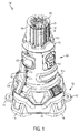
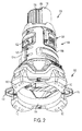
- Figs. 1 and 2 depict front and rear perspective views of a work light 100 including a base portion 102, a main portion 104, and a light module 106, according to an embodiment.
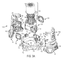
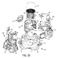
- Figs. 3A and 3B depicts front and rear exploded view of the same work light 100, according to an embodiment. A detailed description of the work light 100 is provided herein with reference to these figures.
- base portion 102 includes a generally cylindrical body 114 defining a large opening and having four legs 110. Two hooks 112 may be additionally provided circumferentially on the base body 114 between adjacent lets 110, in an embodiment.
- a top surface 116 of the base portion 102 includes a non-planar profile including curved portions 118 on top of the legs 110 and provides a mounting surface for the main portion 104, as described below.
- the top surface 116 may additionally include upwardly-projecting posts or pins 119 for securing the main portion 104, as described below.
- main portion 104 includes a main body 120 and two housing halves 104a, 104b mated together partially around the main body 120.
- main body 120 includes a generally-cylindrical upper portion 128 having a smaller diameter than the body 114 of the base portion 102.
- the upper portion 128 of the main body 120 provides a mount and support structure for the light module 106.
- Main body 120 additionally includes a control housing portion 123 for housing a control circuit used to control the operation of the light module 106, as described later in detail.
- two oppositely-arranged handles 122 having gripping surfaces for the users to be able to lift the work light 100 are arranged circumferentially on two sides of the main body 120.
- the handles 122 are supported by the housing halves 104a, 104b, as described below.
- Main body 120 includes a keypad 124 arranged on one side between the handles 122 and a battery receptacle 126 arranged opposite the keypad 124.
- battery receptacle 126 may be provided with a removable door and a locking mechanism for the door so that the battery receptacle is covered when it is not being used.
- work light 100 is additionally provided with a pair of male and female AC plugs 130 and 132.
- the male AC plug 130 may be coupled to an AC power source (e.g., AC mains or a power generator) for supplying AC power to the work light 100.
- Female AC plug 132 receives electric power from the male AC plug 130, thus allowing multiple work lights 100 to be daisy chained together in sequence. This arrangement allow multiple work lights 100 to be powered via the same AC power source throughout the work site.
- control circuit housed in the control housing portion 123 of the main body 120 is electrically connected to the battery receptacle 126, the AC plug 130, the keypad 124, and the light module 106.
- the control circuit supplies power optionally from the male AC plug 130 or the battery receptacle 126 to the light module 106 based on the control options selected by the user via the keypad 124.
- control circuit may be configured to supply electric power from the battery receptacle 126 (i.e., 20V Max DC power) as long as voltage is not detected from the AC plug 130. Once voltage is detected on the AC plug 130, the light module 106 is no longer powered from the battery receptacle 126.
- the switching mechanism (not shown) for the AC and battery power supplies may be, for example, a relay or other current-carrying switch.
- control circuit may additionally include an AC-to-DC converter and/or an adaptor circuit to covert AC power from the AC plug 130 to DC power (e.g., 20V DC, or to a higher voltage level, e.g., 60V DC) suitable for the light module 106.
- control circuit may also be provided with a charging unit (not shown) that charges a battery received in the battery receptacle 126 when AC power is supplied via the AC plug 130.
- a user may control the operation of the light module 106 (i.e., light dimming or other light setting) via keypad 124.
- keypad 124 may include multiple illumination modes for the user to select from.
- the illumination modes correspond to the amount of power received from the power supply and provide illumination within predetermined lumen ranges.
- three illumination modes e.g., left, right, both
- the keypad 124 may additionally include up and down buttons for the user to increase or decrease the amount of illumination (i.e., light intensity) in each mode.
- a BluetoothTM receiver/transmitter may further be provided and coupled to the control circuit, as described later, allowing an operator to control the operation of the light module 106 remotely via a smart phone or similar electronic device.
- the housing halves 104a, 104b each include a mating surface 140 that mate together around the control housing portion 123 of the main body 120 via a plurality of fasteners 105.
- a lower surface 142 of the housing halves 104a, 104b rests on top of the top portion 116 of the base portion 102.
- the lower surface 142 of the housing halves 104a, 104b may include a corresponding profile as the top portion 116 of the base portion 102.
- the lower surface 142 may further include pin receptacles 143 that receive posts 119 of the top portion 116 to secure the housing halves 104a, 104b to the base portion 102.
- the housing halves 104a, 104b when mated together, hold the main body 120 at a distance above the base portion 102.
- housing halves 104a, 104b include oppositelyformed openings 146 that allow access to the keypad 124 and battery receptacle 126. Housing halves 104a, 104b also include side openings 148 that mate together around the handles 122 and circumferentially support the handles 122 around the main body 120. Housing halves further include two openings 150, 151 near the lower surface 142 where male plug 130 and female plug 132 are situated.
- light module 106 includes a generally cylindrical transparent (e.g., plastic) cover 150 disposed around a generally-cylindrical heat sink 152 mounted on the top portion 128 of the main body 120.
- a series of vertically-elongated printed circuit boards (PCBs) 156 are arranged on an outer circumference 154 of the heat sink 152.
- Each PCB 156 includes a series of light-emitting devices (LEDs) 158 mounted thereon.
- PCBs 156 provided a full 360 degrees of illumination around the work light 100.
- a disc-shaped PCB (not shown) with LEDs may be mounted on a top surface of the heat sink 152 to provide additional illumination in a vertical direction.
- Heat sink 152 dissipates heat away from the LEDs 158.
- light module 106 may include a single disc-shaped LED PCB mounted on the top portion 128 of the main body 120 without a heat sink.
- the light module 106 in this embodiment may include a dome-shaped deflector cover 150 to deflect and distribute light all around the work light 100.
- work light 100 of this disclosure is designed such that a user is able to stack multiple works lights on top of one another safely and securely. This design substantially improves storage and transportability of the work lights 100, allowing multiple work lights 100 to be moved in, out, and around the jobsite simultaneously.
- Figs 4 and 5 depict perspective and axial views of an underside of the work light 100, according to an embodiment.
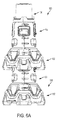
- Figs. 6A and 6B depict side and cross-sectional views of two work lights 100 in a stacked position, respectively. Features of the work light 100 related to its stackability are described herein with reference to these figures, and with continued reference to Figs. 3A and 3B .
- each work light 100 includes a vertical (axial) opening 200 defined between the housing halves 104a and 104, extending longitudinally from the large opening of the base portion 102 previously discussed, to an underside 202 of the control housing portion 123 of the main body 120.
- housing halves 104a and 104b include spaced-apart radial ribs 204 projecting inwardly from an inner surface thereof.
- radial ribs 204 define spaced-apart annular rings forming openings that together define opening 200 in a longitudinal direction.
- ribs 204 are sized to allow vertical opening 200 to receive the light module 106 of another work light 100 therein. This arrangement allows multiple work lights 100 to be stacked on top of one another.
- one or more of the lower ribs 204a are sized to widen a lower portion of the opening 200, such that when two work lights 100 are stacked, lower ribs 204a of the upper work light 100 are disposed around an outer circumference of the top portion 128 of the main body 120 of the lower work light 100. In this position, a top surface 127 of the top portion 128 of the main body 120 engages a lower surface of rib 204b disposed above the lower ribs 204a. A top surface 127 of the top portion 128 of the main body 120 of the lower work light 100 provides a resting surface for the upper work light 100.
- opening 200 includes a first cylindrical compartment 210 sized to receive a light module 106 of a lower work light 100, and a second cylindrical compartment 212 formed in the base portion 102 having a larger diameter to receive at least a portion of the main body 120 of a lower work light 100.
- US Patent Publication No. 2014/0107853 filed March 15, 2014 which is incorporated herein by reference in its entirety, describes a system including a computing device, such as a personal computer, tablet, etc., in communication with power tools, battery packs, chargers, etc. via a wireless communication system such as BluetoothTM, Wi-FiTM, RF, etc.
- a computing device such as a personal computer, tablet, etc.
- a wireless communication system such as BluetoothTM, Wi-FiTM, RF, etc.
- This system is employed, according to an embodiment of the invention, to enable wireless connectivity and control of the above-described work light 100 via a computing device, as described herein.
- a computing device 250 such as a personal computer, tablet, mobile telephone, smartphone, etc. is provided.
- Computing device 250 is preferably connectable to a server 270 via the Internet.
- server 270 via the Internet.
- computing device250 preferably connects to the Internet via a wireless communication circuit/protocol, such as Wi-FiTM, BluetoothTM, ZigbeeTM, 3G/4GTM data systems, etc.
- computing device 250 may be coupled to a variety of rotator or non-rotary power tools, battery packs, battery chargers, etc. via a wireless connection, as described in U.S. Patent Publication No. 2014/0107853 , U.S. Patent Publication No. 2014/0367134 , and PCT Publication No. WO 2013/116303 , each of which is incorporated herein by reference in its entirety. Additionally, computing device 250 may be coupled to work light 100 via a wireless communication unit 300, described in Fig. 8 below. Computing device 250 may include an application or program, as shown in Figs. 9A and 9B , that implements the steps shown in the flow chart of Fig. 10 below for controlling various operation of the work light 100.
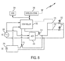
- Fig. 8 depicts a block system diagram of the electronic circuitry within work light 100.
- work light 100 includes a wireless communication circuit, such as Wi-FiTM, BluetoothTM, ZibgeeTM, infrared, RF, etc., coupled to a controller 302.
- Controller 302 may be a programmable chip, such as a micro-controller or micro-processor, or an integrated circuit (i.e., ASIC) chip configured to execute the processes described in this disclosure.
- memory 304 which stores certain data (e.g., identifier for the work light 100, and executable code for controller 302) accessible by the controller 302.
- work light 100 may be powered by either an AC power source 306 via AC plug 130, or a DC power source 308 via battery receptacle 126.
- an AC-to-DC converter 310 e.g., an adaptor circuit including a bridge rectifier and a capacitor
- two electronic switches e.g., FETs
- FETs field-effect transistors
- Controller 302 makes this decision based on detection of voltage on the AC power line.
- controller 302 may control a switching operation of the switches 312, 314 to control the amount of lamination via, e.g., a pulse-width modulation (PWM) control or other known method.
- PWM pulse-width modulation
- work light 100 provides a user the ability to select a mode of operation for turning on only the left half of the light module 106, the right half of the light module, or the full 360 degree area of the light module 106.
- This control may be implemented, in an embodiment via switches 316 and 318, which are controllable by the controller 302, and are coupled to the right LEDs 322 and left LEDs 324.
- Controller 302 selectively turns one or both switches 316 and 318 ON to turn the left half, the right half, or the full light module 106.
- the user may control the described above features (i.e., light dimming, and mode of operation) using keys on keypad 124, as described above.
- the user may use a computing device 250 to control these features, as described herein.
- Figs. 9A and 9B depict exemplary interfaces 400, 420, provided via an app or a program on computing device 250 accessible by the user.
- the user When the user starts the app, the user is provided with a list of all work lights that the device 250 is connected on interface 400. The user may turn all the lights ON or OFF, and/or enable or disable all the lights, via this interface 400.
- the user may also select one light (e.g., Light 1), in which case the user is provided with a second interface 420. In this screen the user may view work light attributes such as battery light, usage, identity, etc.
- the user may also select a mode of operation (i.e., right, left, or both), and increase or decrease light intensity.
- the user may further be provided with the ability to program a schedule for the work light.
- the schedule may include, for example, when the light turns on and off (e.g., every day at 6pm to 10pm), the light intensity level, mode, etc.
- Fig. 10 depicts an exemplary simplified flow diagram used by computing device 250 app or program to control the operation of a work light 100.
- computing device 250 connects wirelessly to wireless communication units 300 of various work lights 100 (at 502).
- the app provides the user with a display interface 400 of all available work lights 100 (at 504).
- the app may also provide the user with a list of all other connected devices such as chargers, battery packs, power tools, etc.
- the app may provide this display in the form of categories of connected products.
- the app receives a selection of a particular work light 100 from the user. Then at 508, the app displays interface 420 particular to that work light 100 to the user. The app then receives an action (e.g., change light intensity, enable, disable, mode, etc.) from the user (at 510). The app then proceeds to communicate that action to the work light 100 controller 302 via wireless communication unit 300.
- an action e.g., change light intensity, enable, disable, mode, etc.
Landscapes
- Engineering & Computer Science (AREA)
- General Engineering & Computer Science (AREA)
- Computer Networks & Wireless Communication (AREA)
- Power Engineering (AREA)
- Arrangement Of Elements, Cooling, Sealing, Or The Like Of Lighting Devices (AREA)
- Circuit Arrangement For Electric Light Sources In General (AREA)
Applications Claiming Priority (2)
| Application Number | Priority Date | Filing Date | Title |
|---|---|---|---|
| US201562168477P | 2015-05-29 | 2015-05-29 | |
| US201562249517P | 2015-11-02 | 2015-11-02 |
Publications (2)
| Publication Number | Publication Date |
|---|---|
| EP3098497A1 true EP3098497A1 (fr) | 2016-11-30 |
| EP3098497B1 EP3098497B1 (fr) | 2018-08-01 |
Family
ID=56117490
Family Applications (1)
| Application Number | Title | Priority Date | Filing Date |
|---|---|---|---|
| EP16171543.8A Active EP3098497B1 (fr) | 2015-05-29 | 2016-05-26 | Lampe de travail |
Country Status (2)
| Country | Link |
|---|---|
| US (6) | US20160348879A1 (fr) |
| EP (1) | EP3098497B1 (fr) |
Cited By (2)
| Publication number | Priority date | Publication date | Assignee | Title |
|---|---|---|---|---|
| WO2025085223A1 (fr) * | 2023-10-16 | 2025-04-24 | Visual Comfort Of America Llc | Module de luminaire rechargeable et appareil d'éclairage sans fil le recevant |
| US12607309B2 (en) | 2023-10-16 | 2026-04-21 | Visual Comfort Of America Llc | Rechargeable luminaire module and cordless light fixture that accommodates the same |
Families Citing this family (16)
| Publication number | Priority date | Publication date | Assignee | Title |
|---|---|---|---|---|
| EP3254016B1 (fr) | 2015-02-04 | 2019-10-02 | Milwaukee Electric Tool Corporation | Luminaire |
| US10041660B2 (en) * | 2015-04-06 | 2018-08-07 | Milwaukee Electric Tool Corporation | Hanging light |
| US10775032B2 (en) * | 2015-07-01 | 2020-09-15 | Milwaukee Electric Tool Corporation | Area light |
| PL3369292T3 (pl) * | 2015-10-30 | 2021-04-06 | Milwaukee Electric Tool Corporation | Zdalne sterowanie, konfiguracja i monitorowanie oświetlenia |
| EP3692298B1 (fr) | 2017-10-06 | 2022-12-07 | Milwaukee Electric Tool Corporation | Lampe de chantier |
| USD946797S1 (en) | 2017-12-01 | 2022-03-22 | Milwaukee Electric Tool Corporation | Hanging light |
| USD870954S1 (en) | 2018-01-18 | 2019-12-24 | Milwaukee Electric Tool Corporation | Light |
| US10412805B1 (en) | 2018-05-16 | 2019-09-10 | Black & Decker Inc. | Control method and apparatus for extending runtime on a portable lighting device |
| US11162668B2 (en) | 2018-10-23 | 2021-11-02 | Milwaukee Electric Tool Corporation | Hanging light |
| USD956293S1 (en) * | 2019-08-26 | 2022-06-28 | Biao Zhang | Lantern |
| US11506332B2 (en) * | 2019-10-01 | 2022-11-22 | Furious Designs LLC | Mated dual support stand assembly |
| WO2021236968A1 (fr) | 2020-05-22 | 2021-11-25 | Black & Decker Inc. | Outil électrique doté d'une enceinte de bloc-batterie |
| CN113775954A (zh) * | 2020-06-10 | 2021-12-10 | 南京德朔实业有限公司 | 便携式照明装置 |
| US11668454B2 (en) | 2021-07-29 | 2023-06-06 | Lumi Legend Electrical Co. Ltd | Work light assembly |
| FI131304B1 (fi) * | 2021-09-28 | 2025-02-03 | Mauri Drufva | Valaisulaite |
| US20240077181A1 (en) * | 2022-09-06 | 2024-03-07 | Milwaukee Electric Tool Corporation | Elevated lighting device and storage system |
Citations (8)
| Publication number | Priority date | Publication date | Assignee | Title |
|---|---|---|---|---|
| ES2101617A1 (es) * | 1993-12-31 | 1997-07-01 | Gonzalez Jose Jorba | Cono de señalizacion. |
| EP1004815A2 (fr) * | 1998-11-26 | 2000-05-31 | Schneider Electric Industries SA | Appareil de signalisation |
| US20060204328A1 (en) * | 2005-03-14 | 2006-09-14 | Frey Steven J | Directional highway buoy |
| US20080036584A1 (en) * | 2006-08-11 | 2008-02-14 | Steve Lang | Flashing flare warning device |
| US20090284963A1 (en) * | 2008-05-15 | 2009-11-19 | Air Systems, Inc. Dba Air Systems International, Inc. | Collapsible portable stand with telescoping support and integral storage case |
| WO2010010070A1 (fr) * | 2008-07-22 | 2010-01-28 | Emp Design Limited | Indicateur lumineux routier |
| WO2011065705A2 (fr) * | 2009-11-27 | 2011-06-03 | 한국광기술원 | Système d'éclairage et appareil d'éclairage le comprenant |
| US20130342131A1 (en) * | 2012-06-19 | 2013-12-26 | Michael V. Recker | Group management of a wireless power outage lighting system |
Family Cites Families (93)
| Publication number | Priority date | Publication date | Assignee | Title |
|---|---|---|---|---|
| US1474401A (en) | 1922-03-25 | 1923-11-20 | Matthew F Bramley | Lantern cage |
| DE2602862A1 (de) | 1976-01-27 | 1977-07-28 | Otmar Ing Grad Greisinger | Mobile warnblinkanlage, vorzugsweise zur abgrenzung des arbeitsbereiches ausserhalb von fahrzeugen bei motor- und reifenpannen, unfaellen, be- und entladevorgaengen usw. |
| USD277739S (en) | 1983-03-14 | 1985-02-26 | Lamba Systems, Inc. | Combined road marker and flashing light |
| GB8804006D0 (en) | 1988-02-20 | 1988-03-23 | Webb R R | Marker light |
| US5192126A (en) * | 1991-08-01 | 1993-03-09 | E-Z Sales And Manufacturing, Inc. | Remote control fluorescent lantern |
| US5294924A (en) | 1992-01-23 | 1994-03-15 | Cads Electronic Systems, Inc. | Flashing warning light for a traffic control device |
| US5890794A (en) | 1996-04-03 | 1999-04-06 | Abtahi; Homayoon | Lighting units |
| US5630660A (en) * | 1996-05-16 | 1997-05-20 | Chen; Wei-Fu | Warning light |
| USD411810S (en) | 1998-09-24 | 1999-07-06 | Presto-Lite, Inc. | Combined safety cone and light |
| GB9903985D0 (en) | 1999-02-23 | 1999-04-14 | Taylor John P | Luminous cone |
| US6634768B2 (en) | 1999-06-17 | 2003-10-21 | Mckenzie Roy L. | Emergency notification system |
| US6425678B1 (en) * | 1999-08-23 | 2002-07-30 | Dialight Corporation | Led obstruction lamp |
| US7682036B2 (en) | 2001-04-11 | 2010-03-23 | General Manufacturing, Inc. | Intrinsically safe light |
| US6857756B2 (en) | 2001-04-11 | 2005-02-22 | General Manufacturing, Inc. | LED work light |
| US6549121B2 (en) | 2001-07-31 | 2003-04-15 | Philip Francis Povey | Illuminated emergency signaling device |
| US6558068B1 (en) | 2001-09-27 | 2003-05-06 | Dennis G. Wittig | Lighted traffic channelization device |
| US20030132852A1 (en) | 2002-01-16 | 2003-07-17 | Povey Philip Francis | Illuminated emergency signaling device |
| US6766760B2 (en) | 2002-01-23 | 2004-07-27 | Worldwide Safety, Llc | Flexible marker device |
| US10180244B2 (en) * | 2002-04-25 | 2019-01-15 | Haralambos A. Stamatatos | Illuminating safety and notification device |
| US7878678B1 (en) | 2002-04-25 | 2011-02-01 | Stamatatos Haralambos A | Illuminating safety and notification device |
| US6769380B1 (en) * | 2002-07-05 | 2004-08-03 | Producciones Generales-Progen S.A. | Modular marker |
| US6877878B2 (en) | 2003-04-14 | 2005-04-12 | Eric J. Raskas | Flashlight and video recorder device |
| US7014337B2 (en) * | 2004-02-02 | 2006-03-21 | Chia Yi Chen | Light device having changeable light members |
| US20060132323A1 (en) | 2004-09-27 | 2006-06-22 | Milex Technologies, Inc. | Strobe beacon |
| DE102006014888B4 (de) | 2005-03-31 | 2009-02-12 | Milwaukee Electric Tool Corp., Brookfield | Leuchteinheit mit Batterieladeaufbau und Scheinwerfer |
| US20070222640A1 (en) | 2006-03-14 | 2007-09-27 | Guelzow Thomas K Ii | Portable hazard marker with sensing and communications systems |
| US20070223236A1 (en) * | 2006-03-24 | 2007-09-27 | Cooper Technologies Company | Method And Apparatus For Storing A Tool On A Worklight |
| US9074736B2 (en) * | 2006-03-28 | 2015-07-07 | Wireless Environment, Llc | Power outage detector and transmitter |
| US8994276B2 (en) * | 2006-03-28 | 2015-03-31 | Wireless Environment, Llc | Grid shifting system for a lighting circuit |
| US20080106430A1 (en) * | 2006-11-02 | 2008-05-08 | Peter Yeh | Modular LED warning lamp |
| DE202007005003U1 (de) * | 2007-04-03 | 2007-07-19 | Aqua Signal Aktiengesellschaft | Leuchte, insbesondere Gefahrenfeuer für Windkraftanlagen |
| USD581304S1 (en) | 2007-07-02 | 2008-11-25 | Phillips Maurice L | Floor warning sign |
| CN101408300B (zh) | 2007-10-10 | 2011-06-08 | 富准精密工业(深圳)有限公司 | 具有散热结构的发光二极管灯具 |
| US8033685B2 (en) | 2008-03-27 | 2011-10-11 | Mcgehee Michael Eugene | LED luminaire |
| US8585260B2 (en) | 2008-05-05 | 2013-11-19 | Nuru Energy Design And Development | Modular illumination device with pedal generator |
| DE112009001556T5 (de) | 2008-06-23 | 2011-04-28 | Milwaukee Electric Tool Corp., Brookfield | Elektrische Anordnung mit einer Akkuladefunktion |
| US8313209B2 (en) | 2008-07-31 | 2012-11-20 | Life+Gear, Inc. | Four-way power source for multifunction tool |
| US8109660B2 (en) | 2008-08-07 | 2012-02-07 | Relume Technologies, Inc. | Globe deployable LED light assembly |
| USD592088S1 (en) | 2008-10-13 | 2009-05-12 | Code 3, Inc. | Light emitting diode (LED) warning light |
| WO2010063001A1 (fr) * | 2008-11-26 | 2010-06-03 | Wireless Environment, Llc | Dispositifs d’éclairage sans fil et applications associées |
| US7810968B1 (en) | 2009-05-15 | 2010-10-12 | Koninklijke Philips Electronics N.V. | LED unit for installation in a post-top luminaire |
| US8157404B2 (en) | 2009-06-22 | 2012-04-17 | Mcdermott Kevin F | Visible light transporter |
| EP2295845A1 (fr) * | 2009-09-09 | 2011-03-16 | Black & Decker Inc. | Lantern |
| JP2013518391A (ja) * | 2010-01-27 | 2013-05-20 | ザ・コールマン・カンパニー・インコーポレイテッド | ワークライト用ストラップ固定システム |
| IT1399161B1 (it) * | 2010-03-26 | 2013-04-11 | Seco S R L | Dispositivo di illuminazione provvisto di mezzi di ricezione e diffusione di contenuti multimediali. |
| US8890435B2 (en) | 2011-03-11 | 2014-11-18 | Ilumi Solutions, Inc. | Wireless lighting control system |
| US8587453B2 (en) | 2011-04-13 | 2013-11-19 | Jeffrey L. Cripps | Portable traffic signaling system |
| US8550653B2 (en) | 2011-05-12 | 2013-10-08 | Aervoe Industries, Inc. | LED flare |
| KR101416897B1 (ko) * | 2011-09-27 | 2014-07-08 | 주식회사 휴닉스 | 엘이디 조명 장치 |
| US20140071681A1 (en) | 2012-03-14 | 2014-03-13 | Project Aj, Inc. | Cone light |
| US8602584B2 (en) | 2012-03-14 | 2013-12-10 | Project Aj, Inc. | Cone light |
| US9091402B2 (en) | 2012-03-28 | 2015-07-28 | Milwaukee Electric Tool Corporation | Area light |
| US9157585B2 (en) | 2012-03-28 | 2015-10-13 | Milwaukee Electric Tool Corporation | Area light |
| US20130265780A1 (en) * | 2012-04-05 | 2013-10-10 | Black & Decker Inc. | Light module and light stand assembly |
| USD669806S1 (en) | 2012-04-18 | 2012-10-30 | Code 3, Inc. | Light emitting diode beacon light |
| USD669807S1 (en) | 2012-04-18 | 2012-10-30 | Code 3, Inc. | Light emitting diode beacon light |
| KR101352563B1 (ko) * | 2012-06-14 | 2014-01-17 | 주식회사 디에스이 | Led전구의 led모듈과 컨버터의 연결장치 |
| US9328881B2 (en) * | 2012-09-21 | 2016-05-03 | Michael Blair Hopper | Rapid deployment lighting system |
| US9035786B2 (en) | 2012-09-24 | 2015-05-19 | Checkers Industrial Products, Llc | LED strobe light with peripheral pattern display |
| US8851706B2 (en) | 2012-10-11 | 2014-10-07 | Abdulreidha Abdulrasoul AlSaffar | Lighted road cone |
| US9046229B2 (en) | 2012-11-07 | 2015-06-02 | Aervoe Industries, Inc. | Stackable LED flare and system |
| WO2014165170A1 (fr) | 2013-03-12 | 2014-10-09 | International Development LLC | Ensemble lampe de travail repliable |
| US9222653B2 (en) * | 2013-03-15 | 2015-12-29 | Lighting Science Group Corporation | Concave low profile luminaire with magnetic lighting devices and associated systems and methods |
| US9328908B2 (en) * | 2013-04-16 | 2016-05-03 | Checkers Industrial Products, Llc | LED strobe light with integrated magnet and heat sink chimney |
| US9062875B2 (en) | 2013-04-25 | 2015-06-23 | Andrew T. NEAL | LED light source |
| US9182088B2 (en) * | 2013-04-30 | 2015-11-10 | Goal Zero Llc | Mobile lantern lighting device |
| USD700859S1 (en) | 2013-05-28 | 2014-03-11 | Neubert Aero Corp. | Stackable runway barrier for airports |
| KR102152643B1 (ko) | 2013-07-04 | 2020-09-08 | 엘지이노텍 주식회사 | 모바일디바이스를 이용한 조명 시스템 |
| US9655211B2 (en) * | 2013-09-23 | 2017-05-16 | Seasonal Specialties, Llc | Lighting |
| US11244558B2 (en) * | 2013-09-23 | 2022-02-08 | Seasonal Specialties, Llc | Lighting |
| US20170163439A1 (en) | 2013-11-14 | 2017-06-08 | LIFI Labs, Inc. | Lighting system |
| CA2874151A1 (fr) | 2013-12-11 | 2015-06-11 | Gemmy Industries Corporation | Systeme d'eclairage decoratif et composants connexes |
| US9526153B2 (en) * | 2014-02-12 | 2016-12-20 | Atif Mohammad Noori | System and method for light socket adaptation |
| CA2939374A1 (fr) * | 2014-03-03 | 2015-09-11 | Laird R. DAUBENSPECK | Systeme d'eclairage a obstruction de balise |
| USD737712S1 (en) | 2014-04-23 | 2015-09-01 | Lind Equipment Ltd. | Beacon light |
| US9493919B2 (en) | 2014-05-23 | 2016-11-15 | Jacquelyn Handy | Traffic barrier assembly |
| US9652979B2 (en) * | 2014-05-30 | 2017-05-16 | Lutron Electronics Co., Inc. | Wireless control device |
| US9313863B2 (en) | 2014-06-02 | 2016-04-12 | Qualcomm Incorporated | Methods, devices, and systems for controlling smart lighting objects to establish a lighting condition |
| US9437109B1 (en) * | 2014-06-24 | 2016-09-06 | Joseph V. Stafford | Emergency safety marker system |
| US9940839B2 (en) * | 2014-06-24 | 2018-04-10 | Strobe Saver, Llc. | Emergency safety marker systems |
| US9949348B2 (en) * | 2014-11-10 | 2018-04-17 | LIFI Labs, Inc. | Lighting connectivity module |
| KR102314643B1 (ko) * | 2014-11-26 | 2021-10-19 | 삼성전자주식회사 | 조명 장치 및 조명 장치의 제어 방법 |
| US10069318B2 (en) | 2014-12-02 | 2018-09-04 | Michael Waters | LED flashlight with longitudinal cooling fins |
| EP3254016B1 (fr) * | 2015-02-04 | 2019-10-02 | Milwaukee Electric Tool Corporation | Luminaire |
| US10378739B2 (en) | 2015-04-24 | 2019-08-13 | Milwaukee Electric Tool Corporation | Stand light |
| US10295990B2 (en) | 2015-05-18 | 2019-05-21 | Milwaukee Electric Tool Corporation | User interface for tool configuration and data capture |
| US20160360598A1 (en) * | 2015-06-04 | 2016-12-08 | Emmanuel Menilik Negatu | Lighting system with wireless connectivity for decorative and other application |
| WO2016201346A1 (fr) * | 2015-06-12 | 2016-12-15 | Villaume Edward | Dispositifs, systèmes et procédés d'éclairage d'urgence |
| US10380883B2 (en) | 2015-06-16 | 2019-08-13 | Milwaukee Electric Tool Corporation | Power tool profile sharing and permissions |
| US9863641B2 (en) * | 2015-07-17 | 2018-01-09 | Marley Engineered Products Llc | Heating appliance with light and sound and corresponding method |
| US9699865B2 (en) | 2015-09-03 | 2017-07-04 | Milwaukee Electric Tool Corporation | Spotlight and method of controlling thereof |
| PL3369292T3 (pl) | 2015-10-30 | 2021-04-06 | Milwaukee Electric Tool Corporation | Zdalne sterowanie, konfiguracja i monitorowanie oświetlenia |
| CA3003146C (fr) | 2015-10-30 | 2020-08-25 | Lutron Electronics Co., Inc. | Mise en service de systemes de commande de charge |
-
2016
- 2016-05-26 EP EP16171543.8A patent/EP3098497B1/fr active Active
- 2016-05-26 US US15/165,060 patent/US20160348879A1/en not_active Abandoned
-
2019
- 2019-02-14 US US16/276,218 patent/US20190178472A1/en not_active Abandoned
- 2019-04-18 US US16/388,118 patent/US20200263855A1/en not_active Abandoned
-
2020
- 2020-10-29 US US17/083,377 patent/US11686454B2/en active Active
-
2023
- 2023-05-05 US US18/312,680 patent/US12480639B2/en active Active
-
2025
- 2025-08-01 US US19/288,443 patent/US20260029108A1/en active Pending
Patent Citations (8)
| Publication number | Priority date | Publication date | Assignee | Title |
|---|---|---|---|---|
| ES2101617A1 (es) * | 1993-12-31 | 1997-07-01 | Gonzalez Jose Jorba | Cono de señalizacion. |
| EP1004815A2 (fr) * | 1998-11-26 | 2000-05-31 | Schneider Electric Industries SA | Appareil de signalisation |
| US20060204328A1 (en) * | 2005-03-14 | 2006-09-14 | Frey Steven J | Directional highway buoy |
| US20080036584A1 (en) * | 2006-08-11 | 2008-02-14 | Steve Lang | Flashing flare warning device |
| US20090284963A1 (en) * | 2008-05-15 | 2009-11-19 | Air Systems, Inc. Dba Air Systems International, Inc. | Collapsible portable stand with telescoping support and integral storage case |
| WO2010010070A1 (fr) * | 2008-07-22 | 2010-01-28 | Emp Design Limited | Indicateur lumineux routier |
| WO2011065705A2 (fr) * | 2009-11-27 | 2011-06-03 | 한국광기술원 | Système d'éclairage et appareil d'éclairage le comprenant |
| US20130342131A1 (en) * | 2012-06-19 | 2013-12-26 | Michael V. Recker | Group management of a wireless power outage lighting system |
Cited By (2)
| Publication number | Priority date | Publication date | Assignee | Title |
|---|---|---|---|---|
| WO2025085223A1 (fr) * | 2023-10-16 | 2025-04-24 | Visual Comfort Of America Llc | Module de luminaire rechargeable et appareil d'éclairage sans fil le recevant |
| US12607309B2 (en) | 2023-10-16 | 2026-04-21 | Visual Comfort Of America Llc | Rechargeable luminaire module and cordless light fixture that accommodates the same |
Also Published As
| Publication number | Publication date |
|---|---|
| US20210041087A1 (en) | 2021-02-11 |
| US20190178472A1 (en) | 2019-06-13 |
| US11686454B2 (en) | 2023-06-27 |
| US20230272901A1 (en) | 2023-08-31 |
| EP3098497B1 (fr) | 2018-08-01 |
| US20200263855A1 (en) | 2020-08-20 |
| US20260029108A1 (en) | 2026-01-29 |
| US20160348879A1 (en) | 2016-12-01 |
| US12480639B2 (en) | 2025-11-25 |
Similar Documents
| Publication | Publication Date | Title |
|---|---|---|
| US12480639B2 (en) | Area light | |
| US12068622B2 (en) | Universal wireless charging of power tool battery packs | |
| US20250183702A1 (en) | Power system for mobile workstation | |
| US9188325B2 (en) | Travel nightlight with USB charger | |
| US20110012518A1 (en) | Lantern with removable lights | |
| US9328881B2 (en) | Rapid deployment lighting system | |
| US20140000771A1 (en) | Carry bag apparatus configured for modular charging | |
| US10299326B2 (en) | USB-powered utility tool | |
| US9728977B2 (en) | Control of power distribution system | |
| EP3439437B1 (fr) | Système d'éclairage et son procédé d'alimentation | |
| US9347633B1 (en) | Cordless decorative lamp | |
| KR101976596B1 (ko) | 매립형 IoT 조명 스위치 장치 | |
| US20170045186A1 (en) | Decorative LED Display | |
| US20170303373A1 (en) | Portable beauty light kit | |
| US20140370743A1 (en) | External Power Supply | |
| US20060197497A1 (en) | Electric accessory | |
| JP3207668U (ja) | 卓上充電スタンド | |
| US9510412B2 (en) | Lighting system | |
| WO2015011693A2 (fr) | Appareil d'éclairage modulaire | |
| JP2020527281A (ja) | 電力潮流方向の制御を有する照明デバイス | |
| KR101193489B1 (ko) | 다각 방광 조명장치 | |
| CN205754981U (zh) | 照明装置 | |
| US20100271801A1 (en) | Storm Light |
Legal Events
| Date | Code | Title | Description |
|---|---|---|---|
| PUAI | Public reference made under article 153(3) epc to a published international application that has entered the european phase |
Free format text: ORIGINAL CODE: 0009012 |
|
| AK | Designated contracting states |
Kind code of ref document: A1 Designated state(s): AL AT BE BG CH CY CZ DE DK EE ES FI FR GB GR HR HU IE IS IT LI LT LU LV MC MK MT NL NO PL PT RO RS SE SI SK SM TR |
|
| AX | Request for extension of the european patent |
Extension state: BA ME |
|
| STAA | Information on the status of an ep patent application or granted ep patent |
Free format text: STATUS: REQUEST FOR EXAMINATION WAS MADE |
|
| 17P | Request for examination filed |
Effective date: 20161205 |
|
| RBV | Designated contracting states (corrected) |
Designated state(s): AL AT BE BG CH CY CZ DE DK EE ES FI FR GB GR HR HU IE IS IT LI LT LU LV MC MK MT NL NO PL PT RO RS SE SI SK SM TR |
|
| GRAP | Despatch of communication of intention to grant a patent |
Free format text: ORIGINAL CODE: EPIDOSNIGR1 |
|
| STAA | Information on the status of an ep patent application or granted ep patent |
Free format text: STATUS: GRANT OF PATENT IS INTENDED |
|
| RIC1 | Information provided on ipc code assigned before grant |
Ipc: F21V 23/00 20150101ALN20180125BHEP Ipc: F21Y 111/00 20160101ALN20180125BHEP Ipc: F21V 15/01 20060101ALN20180125BHEP Ipc: F21W 131/10 20060101ALN20180125BHEP Ipc: F21V 23/04 20060101ALI20180125BHEP Ipc: F21Y 115/10 20160101ALN20180125BHEP Ipc: F21Y 107/30 20160101ALN20180125BHEP Ipc: F21L 2/00 20060101AFI20180125BHEP Ipc: F21L 4/00 20060101ALI20180125BHEP |
|
| INTG | Intention to grant announced |
Effective date: 20180228 |
|
| GRAS | Grant fee paid |
Free format text: ORIGINAL CODE: EPIDOSNIGR3 |
|
| GRAA | (expected) grant |
Free format text: ORIGINAL CODE: 0009210 |
|
| STAA | Information on the status of an ep patent application or granted ep patent |
Free format text: STATUS: THE PATENT HAS BEEN GRANTED |
|
| AK | Designated contracting states |
Kind code of ref document: B1 Designated state(s): AL AT BE BG CH CY CZ DE DK EE ES FI FR GB GR HR HU IE IS IT LI LT LU LV MC MK MT NL NO PL PT RO RS SE SI SK SM TR |
|
| REG | Reference to a national code |
Ref country code: GB Ref legal event code: FG4D |
|
| REG | Reference to a national code |
Ref country code: CH Ref legal event code: EP Ref country code: AT Ref legal event code: REF Ref document number: 1024722 Country of ref document: AT Kind code of ref document: T Effective date: 20180815 |
|
| REG | Reference to a national code |
Ref country code: IE Ref legal event code: FG4D |
|
| REG | Reference to a national code |
Ref country code: DE Ref legal event code: R096 Ref document number: 602016004414 Country of ref document: DE |
|
| REG | Reference to a national code |
Ref country code: NL Ref legal event code: MP Effective date: 20180801 |
|
| REG | Reference to a national code |
Ref country code: LT Ref legal event code: MG4D |
|
| REG | Reference to a national code |
Ref country code: AT Ref legal event code: MK05 Ref document number: 1024722 Country of ref document: AT Kind code of ref document: T Effective date: 20180801 |
|
| PG25 | Lapsed in a contracting state [announced via postgrant information from national office to epo] |
Ref country code: GR Free format text: LAPSE BECAUSE OF FAILURE TO SUBMIT A TRANSLATION OF THE DESCRIPTION OR TO PAY THE FEE WITHIN THE PRESCRIBED TIME-LIMIT Effective date: 20181102 Ref country code: SE Free format text: LAPSE BECAUSE OF FAILURE TO SUBMIT A TRANSLATION OF THE DESCRIPTION OR TO PAY THE FEE WITHIN THE PRESCRIBED TIME-LIMIT Effective date: 20180801 Ref country code: NL Free format text: LAPSE BECAUSE OF FAILURE TO SUBMIT A TRANSLATION OF THE DESCRIPTION OR TO PAY THE FEE WITHIN THE PRESCRIBED TIME-LIMIT Effective date: 20180801 Ref country code: BG Free format text: LAPSE BECAUSE OF FAILURE TO SUBMIT A TRANSLATION OF THE DESCRIPTION OR TO PAY THE FEE WITHIN THE PRESCRIBED TIME-LIMIT Effective date: 20181101 Ref country code: LT Free format text: LAPSE BECAUSE OF FAILURE TO SUBMIT A TRANSLATION OF THE DESCRIPTION OR TO PAY THE FEE WITHIN THE PRESCRIBED TIME-LIMIT Effective date: 20180801 Ref country code: PL Free format text: LAPSE BECAUSE OF FAILURE TO SUBMIT A TRANSLATION OF THE DESCRIPTION OR TO PAY THE FEE WITHIN THE PRESCRIBED TIME-LIMIT Effective date: 20180801 Ref country code: FI Free format text: LAPSE BECAUSE OF FAILURE TO SUBMIT A TRANSLATION OF THE DESCRIPTION OR TO PAY THE FEE WITHIN THE PRESCRIBED TIME-LIMIT Effective date: 20180801 Ref country code: RS Free format text: LAPSE BECAUSE OF FAILURE TO SUBMIT A TRANSLATION OF THE DESCRIPTION OR TO PAY THE FEE WITHIN THE PRESCRIBED TIME-LIMIT Effective date: 20180801 Ref country code: AT Free format text: LAPSE BECAUSE OF FAILURE TO SUBMIT A TRANSLATION OF THE DESCRIPTION OR TO PAY THE FEE WITHIN THE PRESCRIBED TIME-LIMIT Effective date: 20180801 Ref country code: NO Free format text: LAPSE BECAUSE OF FAILURE TO SUBMIT A TRANSLATION OF THE DESCRIPTION OR TO PAY THE FEE WITHIN THE PRESCRIBED TIME-LIMIT Effective date: 20181101 Ref country code: IS Free format text: LAPSE BECAUSE OF FAILURE TO SUBMIT A TRANSLATION OF THE DESCRIPTION OR TO PAY THE FEE WITHIN THE PRESCRIBED TIME-LIMIT Effective date: 20181201 |
|
| PG25 | Lapsed in a contracting state [announced via postgrant information from national office to epo] |
Ref country code: AL Free format text: LAPSE BECAUSE OF FAILURE TO SUBMIT A TRANSLATION OF THE DESCRIPTION OR TO PAY THE FEE WITHIN THE PRESCRIBED TIME-LIMIT Effective date: 20180801 Ref country code: LV Free format text: LAPSE BECAUSE OF FAILURE TO SUBMIT A TRANSLATION OF THE DESCRIPTION OR TO PAY THE FEE WITHIN THE PRESCRIBED TIME-LIMIT Effective date: 20180801 Ref country code: HR Free format text: LAPSE BECAUSE OF FAILURE TO SUBMIT A TRANSLATION OF THE DESCRIPTION OR TO PAY THE FEE WITHIN THE PRESCRIBED TIME-LIMIT Effective date: 20180801 |
|
| PG25 | Lapsed in a contracting state [announced via postgrant information from national office to epo] |
Ref country code: RO Free format text: LAPSE BECAUSE OF FAILURE TO SUBMIT A TRANSLATION OF THE DESCRIPTION OR TO PAY THE FEE WITHIN THE PRESCRIBED TIME-LIMIT Effective date: 20180801 Ref country code: IT Free format text: LAPSE BECAUSE OF FAILURE TO SUBMIT A TRANSLATION OF THE DESCRIPTION OR TO PAY THE FEE WITHIN THE PRESCRIBED TIME-LIMIT Effective date: 20180801 Ref country code: EE Free format text: LAPSE BECAUSE OF FAILURE TO SUBMIT A TRANSLATION OF THE DESCRIPTION OR TO PAY THE FEE WITHIN THE PRESCRIBED TIME-LIMIT Effective date: 20180801 Ref country code: ES Free format text: LAPSE BECAUSE OF FAILURE TO SUBMIT A TRANSLATION OF THE DESCRIPTION OR TO PAY THE FEE WITHIN THE PRESCRIBED TIME-LIMIT Effective date: 20180801 Ref country code: CZ Free format text: LAPSE BECAUSE OF FAILURE TO SUBMIT A TRANSLATION OF THE DESCRIPTION OR TO PAY THE FEE WITHIN THE PRESCRIBED TIME-LIMIT Effective date: 20180801 |
|
| REG | Reference to a national code |
Ref country code: DE Ref legal event code: R097 Ref document number: 602016004414 Country of ref document: DE |
|
| PG25 | Lapsed in a contracting state [announced via postgrant information from national office to epo] |
Ref country code: SK Free format text: LAPSE BECAUSE OF FAILURE TO SUBMIT A TRANSLATION OF THE DESCRIPTION OR TO PAY THE FEE WITHIN THE PRESCRIBED TIME-LIMIT Effective date: 20180801 Ref country code: DK Free format text: LAPSE BECAUSE OF FAILURE TO SUBMIT A TRANSLATION OF THE DESCRIPTION OR TO PAY THE FEE WITHIN THE PRESCRIBED TIME-LIMIT Effective date: 20180801 Ref country code: SM Free format text: LAPSE BECAUSE OF FAILURE TO SUBMIT A TRANSLATION OF THE DESCRIPTION OR TO PAY THE FEE WITHIN THE PRESCRIBED TIME-LIMIT Effective date: 20180801 |
|
| PLBE | No opposition filed within time limit |
Free format text: ORIGINAL CODE: 0009261 |
|
| STAA | Information on the status of an ep patent application or granted ep patent |
Free format text: STATUS: NO OPPOSITION FILED WITHIN TIME LIMIT |
|
| 26N | No opposition filed |
Effective date: 20190503 |
|
| PG25 | Lapsed in a contracting state [announced via postgrant information from national office to epo] |
Ref country code: SI Free format text: LAPSE BECAUSE OF FAILURE TO SUBMIT A TRANSLATION OF THE DESCRIPTION OR TO PAY THE FEE WITHIN THE PRESCRIBED TIME-LIMIT Effective date: 20180801 |
|
| REG | Reference to a national code |
Ref country code: CH Ref legal event code: PL |
|
| PG25 | Lapsed in a contracting state [announced via postgrant information from national office to epo] |
Ref country code: CH Free format text: LAPSE BECAUSE OF NON-PAYMENT OF DUE FEES Effective date: 20190531 Ref country code: LI Free format text: LAPSE BECAUSE OF NON-PAYMENT OF DUE FEES Effective date: 20190531 Ref country code: MC Free format text: LAPSE BECAUSE OF FAILURE TO SUBMIT A TRANSLATION OF THE DESCRIPTION OR TO PAY THE FEE WITHIN THE PRESCRIBED TIME-LIMIT Effective date: 20180801 |
|
| REG | Reference to a national code |
Ref country code: BE Ref legal event code: MM Effective date: 20190531 |
|
| PG25 | Lapsed in a contracting state [announced via postgrant information from national office to epo] |
Ref country code: LU Free format text: LAPSE BECAUSE OF NON-PAYMENT OF DUE FEES Effective date: 20190526 |
|
| PG25 | Lapsed in a contracting state [announced via postgrant information from national office to epo] |
Ref country code: TR Free format text: LAPSE BECAUSE OF FAILURE TO SUBMIT A TRANSLATION OF THE DESCRIPTION OR TO PAY THE FEE WITHIN THE PRESCRIBED TIME-LIMIT Effective date: 20180801 |
|
| PG25 | Lapsed in a contracting state [announced via postgrant information from national office to epo] |
Ref country code: IE Free format text: LAPSE BECAUSE OF NON-PAYMENT OF DUE FEES Effective date: 20190526 |
|
| PG25 | Lapsed in a contracting state [announced via postgrant information from national office to epo] |
Ref country code: BE Free format text: LAPSE BECAUSE OF NON-PAYMENT OF DUE FEES Effective date: 20190531 |
|
| PG25 | Lapsed in a contracting state [announced via postgrant information from national office to epo] |
Ref country code: FR Free format text: LAPSE BECAUSE OF NON-PAYMENT OF DUE FEES Effective date: 20190531 Ref country code: PT Free format text: LAPSE BECAUSE OF FAILURE TO SUBMIT A TRANSLATION OF THE DESCRIPTION OR TO PAY THE FEE WITHIN THE PRESCRIBED TIME-LIMIT Effective date: 20181201 |
|
| PG25 | Lapsed in a contracting state [announced via postgrant information from national office to epo] |
Ref country code: CY Free format text: LAPSE BECAUSE OF FAILURE TO SUBMIT A TRANSLATION OF THE DESCRIPTION OR TO PAY THE FEE WITHIN THE PRESCRIBED TIME-LIMIT Effective date: 20180801 |
|
| PG25 | Lapsed in a contracting state [announced via postgrant information from national office to epo] |
Ref country code: MT Free format text: LAPSE BECAUSE OF FAILURE TO SUBMIT A TRANSLATION OF THE DESCRIPTION OR TO PAY THE FEE WITHIN THE PRESCRIBED TIME-LIMIT Effective date: 20180801 Ref country code: HU Free format text: LAPSE BECAUSE OF FAILURE TO SUBMIT A TRANSLATION OF THE DESCRIPTION OR TO PAY THE FEE WITHIN THE PRESCRIBED TIME-LIMIT; INVALID AB INITIO Effective date: 20160526 |
|
| PG25 | Lapsed in a contracting state [announced via postgrant information from national office to epo] |
Ref country code: MK Free format text: LAPSE BECAUSE OF FAILURE TO SUBMIT A TRANSLATION OF THE DESCRIPTION OR TO PAY THE FEE WITHIN THE PRESCRIBED TIME-LIMIT Effective date: 20180801 |
|
| PGFP | Annual fee paid to national office [announced via postgrant information from national office to epo] |
Ref country code: DE Payment date: 20250519 Year of fee payment: 10 |
|
| PGFP | Annual fee paid to national office [announced via postgrant information from national office to epo] |
Ref country code: GB Payment date: 20260324 Year of fee payment: 11 |