EP3098505A1 - Flugzeugleuchte und zentrale integration zusätzlichen funktionen - Google Patents
Flugzeugleuchte und zentrale integration zusätzlichen funktionen Download PDFInfo
- Publication number
- EP3098505A1 EP3098505A1 EP16171344.1A EP16171344A EP3098505A1 EP 3098505 A1 EP3098505 A1 EP 3098505A1 EP 16171344 A EP16171344 A EP 16171344A EP 3098505 A1 EP3098505 A1 EP 3098505A1
- Authority
- EP
- European Patent Office
- Prior art keywords
- diodes
- support
- light
- reflector
- cylindrical
- Prior art date
- Legal status (The legal status is an assumption and is not a legal conclusion. Google has not performed a legal analysis and makes no representation as to the accuracy of the status listed.)
- Granted
Links
Images

Classifications
-
- B—PERFORMING OPERATIONS; TRANSPORTING
- B64—AIRCRAFT; AVIATION; COSMONAUTICS
- B64D—EQUIPMENT FOR FITTING IN OR TO AIRCRAFT; FLIGHT SUITS; PARACHUTES; ARRANGEMENT OR MOUNTING OF POWER PLANTS OR PROPULSION TRANSMISSIONS IN AIRCRAFT
- B64D47/00—Equipment not otherwise provided for
- B64D47/02—Arrangements or adaptations of signal or lighting devices
-
- B—PERFORMING OPERATIONS; TRANSPORTING
- B64—AIRCRAFT; AVIATION; COSMONAUTICS
- B64D—EQUIPMENT FOR FITTING IN OR TO AIRCRAFT; FLIGHT SUITS; PARACHUTES; ARRANGEMENT OR MOUNTING OF POWER PLANTS OR PROPULSION TRANSMISSIONS IN AIRCRAFT
- B64D47/00—Equipment not otherwise provided for
- B64D47/02—Arrangements or adaptations of signal or lighting devices
- B64D47/04—Arrangements or adaptations of signal or lighting devices the lighting devices being primarily intended to illuminate the way ahead
-
- F—MECHANICAL ENGINEERING; LIGHTING; HEATING; WEAPONS; BLASTING
- F21—LIGHTING
- F21V—FUNCTIONAL FEATURES OR DETAILS OF LIGHTING DEVICES OR SYSTEMS THEREOF; STRUCTURAL COMBINATIONS OF LIGHTING DEVICES WITH OTHER ARTICLES, NOT OTHERWISE PROVIDED FOR
- F21V23/00—Arrangement of electric circuit elements in or on lighting devices
- F21V23/04—Arrangement of electric circuit elements in or on lighting devices the elements being switches
- F21V23/0442—Arrangement of electric circuit elements in or on lighting devices the elements being switches activated by means of a sensor, e.g. motion or photodetectors
- F21V23/0471—Arrangement of electric circuit elements in or on lighting devices the elements being switches activated by means of a sensor, e.g. motion or photodetectors the sensor detecting the proximity, the presence or the movement of an object or a person
- F21V23/0478—Arrangement of electric circuit elements in or on lighting devices the elements being switches activated by means of a sensor, e.g. motion or photodetectors the sensor detecting the proximity, the presence or the movement of an object or a person by means of an image recording device, e.g. a camera
-
- F—MECHANICAL ENGINEERING; LIGHTING; HEATING; WEAPONS; BLASTING
- F21—LIGHTING
- F21V—FUNCTIONAL FEATURES OR DETAILS OF LIGHTING DEVICES OR SYSTEMS THEREOF; STRUCTURAL COMBINATIONS OF LIGHTING DEVICES WITH OTHER ARTICLES, NOT OTHERWISE PROVIDED FOR
- F21V29/00—Protecting lighting devices from thermal damage; Cooling or heating arrangements specially adapted for lighting devices or systems
- F21V29/50—Cooling arrangements
- F21V29/70—Cooling arrangements characterised by passive heat-dissipating elements, e.g. heat-sinks
-
- F—MECHANICAL ENGINEERING; LIGHTING; HEATING; WEAPONS; BLASTING
- F21—LIGHTING
- F21V—FUNCTIONAL FEATURES OR DETAILS OF LIGHTING DEVICES OR SYSTEMS THEREOF; STRUCTURAL COMBINATIONS OF LIGHTING DEVICES WITH OTHER ARTICLES, NOT OTHERWISE PROVIDED FOR
- F21V3/00—Globes; Bowls; Cover glasses
- F21V3/04—Globes; Bowls; Cover glasses characterised by materials, surface treatments or coatings
- F21V3/06—Globes; Bowls; Cover glasses characterised by materials, surface treatments or coatings characterised by the material
- F21V3/061—Globes; Bowls; Cover glasses characterised by materials, surface treatments or coatings characterised by the material the material being glass
-
- F—MECHANICAL ENGINEERING; LIGHTING; HEATING; WEAPONS; BLASTING
- F21—LIGHTING
- F21V—FUNCTIONAL FEATURES OR DETAILS OF LIGHTING DEVICES OR SYSTEMS THEREOF; STRUCTURAL COMBINATIONS OF LIGHTING DEVICES WITH OTHER ARTICLES, NOT OTHERWISE PROVIDED FOR
- F21V33/00—Structural combinations of lighting devices with other articles, not otherwise provided for
- F21V33/0064—Health, life-saving or fire-fighting equipment
- F21V33/0076—Safety or security signalisation, e.g. smoke or burglar alarms, earthquake detectors; Self-defence devices
-
- F—MECHANICAL ENGINEERING; LIGHTING; HEATING; WEAPONS; BLASTING
- F21—LIGHTING
- F21V—FUNCTIONAL FEATURES OR DETAILS OF LIGHTING DEVICES OR SYSTEMS THEREOF; STRUCTURAL COMBINATIONS OF LIGHTING DEVICES WITH OTHER ARTICLES, NOT OTHERWISE PROVIDED FOR
- F21V7/00—Reflectors for light sources
- F21V7/0008—Reflectors for light sources providing for indirect lighting
-
- F—MECHANICAL ENGINEERING; LIGHTING; HEATING; WEAPONS; BLASTING
- F21—LIGHTING
- F21V—FUNCTIONAL FEATURES OR DETAILS OF LIGHTING DEVICES OR SYSTEMS THEREOF; STRUCTURAL COMBINATIONS OF LIGHTING DEVICES WITH OTHER ARTICLES, NOT OTHERWISE PROVIDED FOR
- F21V7/00—Reflectors for light sources
- F21V7/0083—Array of reflectors for a cluster of light sources, e.g. arrangement of multiple light sources in one plane
-
- F—MECHANICAL ENGINEERING; LIGHTING; HEATING; WEAPONS; BLASTING
- F21—LIGHTING
- F21V—FUNCTIONAL FEATURES OR DETAILS OF LIGHTING DEVICES OR SYSTEMS THEREOF; STRUCTURAL COMBINATIONS OF LIGHTING DEVICES WITH OTHER ARTICLES, NOT OTHERWISE PROVIDED FOR
- F21V7/00—Reflectors for light sources
- F21V7/04—Optical design
- F21V7/06—Optical design with parabolic curvature
-
- F—MECHANICAL ENGINEERING; LIGHTING; HEATING; WEAPONS; BLASTING
- F21—LIGHTING
- F21V—FUNCTIONAL FEATURES OR DETAILS OF LIGHTING DEVICES OR SYSTEMS THEREOF; STRUCTURAL COMBINATIONS OF LIGHTING DEVICES WITH OTHER ARTICLES, NOT OTHERWISE PROVIDED FOR
- F21V7/00—Reflectors for light sources
- F21V7/22—Reflectors for light sources characterised by materials, surface treatments or coatings, e.g. dichroic reflectors
- F21V7/24—Reflectors for light sources characterised by materials, surface treatments or coatings, e.g. dichroic reflectors characterised by the material
-
- F—MECHANICAL ENGINEERING; LIGHTING; HEATING; WEAPONS; BLASTING
- F21—LIGHTING
- F21V—FUNCTIONAL FEATURES OR DETAILS OF LIGHTING DEVICES OR SYSTEMS THEREOF; STRUCTURAL COMBINATIONS OF LIGHTING DEVICES WITH OTHER ARTICLES, NOT OTHERWISE PROVIDED FOR
- F21V7/00—Reflectors for light sources
- F21V7/22—Reflectors for light sources characterised by materials, surface treatments or coatings, e.g. dichroic reflectors
- F21V7/28—Reflectors for light sources characterised by materials, surface treatments or coatings, e.g. dichroic reflectors characterised by coatings
-
- G—PHYSICS
- G08—SIGNALLING
- G08G—TRAFFIC CONTROL SYSTEMS
- G08G5/00—Traffic control systems for aircraft
- G08G5/50—Navigation or guidance aids
- G08G5/54—Navigation or guidance aids for approach or landing
-
- B—PERFORMING OPERATIONS; TRANSPORTING
- B64—AIRCRAFT; AVIATION; COSMONAUTICS
- B64D—EQUIPMENT FOR FITTING IN OR TO AIRCRAFT; FLIGHT SUITS; PARACHUTES; ARRANGEMENT OR MOUNTING OF POWER PLANTS OR PROPULSION TRANSMISSIONS IN AIRCRAFT
- B64D2203/00—Aircraft or airfield lights using LEDs
-
- B—PERFORMING OPERATIONS; TRANSPORTING
- B64—AIRCRAFT; AVIATION; COSMONAUTICS
- B64D—EQUIPMENT FOR FITTING IN OR TO AIRCRAFT; FLIGHT SUITS; PARACHUTES; ARRANGEMENT OR MOUNTING OF POWER PLANTS OR PROPULSION TRANSMISSIONS IN AIRCRAFT
- B64D47/00—Equipment not otherwise provided for
- B64D47/08—Arrangements of cameras
-
- F—MECHANICAL ENGINEERING; LIGHTING; HEATING; WEAPONS; BLASTING
- F21—LIGHTING
- F21W—INDEXING SCHEME ASSOCIATED WITH SUBCLASSES F21K, F21L, F21S and F21V, RELATING TO USES OR APPLICATIONS OF LIGHTING DEVICES OR SYSTEMS
- F21W2107/00—Use or application of lighting devices on or in particular types of vehicles
- F21W2107/30—Use or application of lighting devices on or in particular types of vehicles for aircraft
-
- F—MECHANICAL ENGINEERING; LIGHTING; HEATING; WEAPONS; BLASTING
- F21—LIGHTING
- F21Y—INDEXING SCHEME ASSOCIATED WITH SUBCLASSES F21K, F21L, F21S and F21V, RELATING TO THE FORM OR THE KIND OF THE LIGHT SOURCES OR OF THE COLOUR OF THE LIGHT EMITTED
- F21Y2101/00—Point-like light sources
-
- F—MECHANICAL ENGINEERING; LIGHTING; HEATING; WEAPONS; BLASTING
- F21—LIGHTING
- F21Y—INDEXING SCHEME ASSOCIATED WITH SUBCLASSES F21K, F21L, F21S and F21V, RELATING TO THE FORM OR THE KIND OF THE LIGHT SOURCES OR OF THE COLOUR OF THE LIGHT EMITTED
- F21Y2107/00—Light sources with three-dimensionally disposed light-generating elements
- F21Y2107/30—Light sources with three-dimensionally disposed light-generating elements on the outer surface of cylindrical surfaces, e.g. rod-shaped supports having a circular or a polygonal cross section
-
- F—MECHANICAL ENGINEERING; LIGHTING; HEATING; WEAPONS; BLASTING
- F21—LIGHTING
- F21Y—INDEXING SCHEME ASSOCIATED WITH SUBCLASSES F21K, F21L, F21S and F21V, RELATING TO THE FORM OR THE KIND OF THE LIGHT SOURCES OR OF THE COLOUR OF THE LIGHT EMITTED
- F21Y2115/00—Light-generating elements of semiconductor light sources
- F21Y2115/10—Light-emitting diodes [LED]
-
- G—PHYSICS
- G01—MEASURING; TESTING
- G01S—RADIO DIRECTION-FINDING; RADIO NAVIGATION; DETERMINING DISTANCE OR VELOCITY BY USE OF RADIO WAVES; LOCATING OR PRESENCE-DETECTING BY USE OF THE REFLECTION OR RERADIATION OF RADIO WAVES; ANALOGOUS ARRANGEMENTS USING OTHER WAVES
- G01S13/00—Systems using the reflection or reradiation of radio waves, e.g. radar systems; Analogous systems using reflection or reradiation of waves whose nature or wavelength is irrelevant or unspecified
- G01S13/88—Radar or analogous systems specially adapted for specific applications
- G01S13/93—Radar or analogous systems specially adapted for specific applications for anti-collision purposes
- G01S13/933—Radar or analogous systems specially adapted for specific applications for anti-collision purposes of aircraft or spacecraft
- G01S13/934—Radar or analogous systems specially adapted for specific applications for anti-collision purposes of aircraft or spacecraft on airport surfaces, e.g. while taxiing
Definitions
- the invention relates, in general, to light emitting diode (LED) lighting devices for aircraft.
- LED light emitting diode
- the invention relates to a LED projector type "take-off light” or “landing light” or a projector type “taxi light”.
- an aircraft generally comprises a plurality of external lighting devices, each intended for illumination of an outer zone and which are activated according to the phases of flight or taxiing of the aircraft.
- the lighting system of an aircraft is thus capable of providing a taxi function, generally designated by the English term “taxi light”, a take-off function, and a function of landing (landing light).
- the invention also relates to a helicopter lighting device for use as a search and landing searchlight.
- Aircraft takeoff and landing spotlights that is to say the projectors known by the English terms “take-off light” and “landing light”, as well as the search and landing spotlights for helicopter are extremely powerful in order to have a sufficient range, for example of the order of 200 to 500 m to effectively illuminate the runway, for aircraft takeoff and landing lights, or the ground , with regard to search and landing helicopter searchlights. They are thus generally able to supply several hundreds of thousands of candelas.
- the size of the projectors, as well as the luminous intensity they are capable of providing, are criteria that must be considered when designing the projectors.
- the size of the projectors is generally designated by the number of PAR, which designates the diameter of the projector in 8 th of an inch.
- the size PAR 36 corresponds to a diameter of 4 1 ⁇ 2 inches, ie 114 mm
- PAR 46 corresponds to a diameter of 5 inches 3 ⁇ 4
- PAR 64 corresponds to a diameter of 8 inches, ie 203 mm.
- the take-off and landing lights used on passenger planes and certain helicopters and equipped with a halogen source are generally of the PAR 64 size.
- Lighting systems Recent examples using light-emitting diode sources have similar frontal dimensions. They have a diameter of about 200 mm.
- the LED projectors comprise a reflector having in section a generally parabolic section, inside which is mounted an array of electroluminescent diodes bonded together and arranged near the focal axis of the parabola defined by the reflector .
- the light-emitting diodes are oriented in the direction to be illuminated.
- the object of the invention is to propose a lighting device for light-emitting diode-based aircraft comprising a sufficient number of diodes to obtain a power and therefore a sufficient range while allowing the integration of a device capable of performing an additional function.
- the invention therefore relates to an aircraft lighting device comprising a cylindrical hollow body, a set of light-emitting diodes mounted in the hollow body and at least one reflector receiving the light beams emitted by the diodes and adapted to direct them in the lighting direction of the device.
- the diodes are mounted on a cylindrical support so that the diodes are arranged radially in the cylindrical body.
- Such an arrangement also makes it possible to substantially reduce the overall size of the light sources because it makes it possible to densify the LEDs, that is to say to increase the number thereof and, consequently, to release a volume that can be used to the installation of a radiator capable of dissipating the heat released by the diodes or by their electronic supply card. It is thus possible to obtain performances similar to those of a larger projector.
- Such a space can also be used to place in the projector a device capable of performing other functions, such as an obstacle detector or a camera.
- the cylindrical support is a cylindrical support with a polygonal contour. In other words, it is a cylindrical support with a polygonal base.
- each side of the cylindrical support polygonal contour comprises several diodes.
- the support is an annular support, at least one member for executing an additional function being mounted in the center of the annular support
- the lighting device may comprise at least one member for executing an additional function that may be chosen from a camera, a radar or a sensor.
- the executing member of an additional function is covered with an ice transparent to a radiation emitted and / or detected by said member.
- the ice is equipped with deicing means.
- the support comprises an anterior face comprising an annular radiator for dissipating thermal energy, said radiator being annular or disc-shaped.
- the diodes are mounted on at least one printed circuit fixed on the support.
- the device comprises an electronic card supply diodes mounted in the body.
- It may further comprise an annular ice sealingly covering the diodes and the reflector.
- the body has a rear face that may include a heat dissipation radiator.
- the device comprises a set of juxtaposed revolution reflecting elements having a typically parabolic generator.
- each diode is associated with a reflective element.
- reflector elements are mounted inclined with respect to the illumination direction of the device.
- the reflective elements are injected plastic material covered with a layer of aluminum reflecting light.
- Such a lighting device is intended to constitute a landing light or "landing light” or a take-off light or "take-off light”.
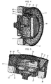
- the device 1 is a "PAR 64" format projector.
- the lighting device here comprises a body 2 comprising a front face 3 turned in the direction of light emission and an opposite rear face 4.
- the body 2 has a hollow cylinder shape closed by a bottom 5 on the side of the rear face 4 and here having a diameter of 203 mm.
- the cylindrical body internally comprises a support 6 on which are mounted a set of diodes 7.
- the support may have various shapes.
- the cylindrical support is polygonal and has a generally annular shape.
- the annular support comprises a cylindrical inner wall 8, a polygonal outer face 9 on which the diodes 7 are mounted, extending towards the front by a cylindrical end edge.
- the polygonal contour of the support here octagonal, constitutes the mounting zone of the LEDs.
- Each side of the polygonal support here comprises five diodes mounted on a printed circuit, preferably an insulated metal substrate printed circuit (or SMI) particularly adapted to receive power diodes.
- a printed circuit preferably an insulated metal substrate printed circuit (or SMI) particularly adapted to receive power diodes.
- each side of the polygonal support receives five diodes so that the device comprises 40 diodes regularly distributed around the polygonal support.
- the device comprises 8 reflectors 11 consisting of several sets of juxtaposed reflective elements each positioned on one of the polygonal sides of the support.
- the reflector elements consist of revolution mirror portions, typically parabolic, and are each arranged opposite a light-emitting diode.
- annular mirror 13 transparent to light, is fixed on the body 3 and in a groove made in the cylindrical end edge 10 of the support, in the path of the light beams emitted by the diodes and reflected by the reflector elements.
- the light-emitting diodes are powered by an electronic supply card 14, here annular, fixed on the support, which is housed between the outer face of the inner cylindrical wall and the inner face of the polygonal wall of the support.
- the mounting of the diodes in the cylindrical body radially on a support with a polygonal contour and the use of an annular mirror make it possible to disengage a housing L at the center of the lighting device.
- the polygonal support may comprise a closed front face 15 shaped so as to form a radiator capable of evacuating the thermal energy released by the diodes and by the electronic supply card during operation of the device.
- radiator on the front face is indeed advantageous insofar as this face is often exposed to the external elements and is therefore well cooled.
- the device comprises one or more additional equipment 17 capable of performing additional functions.
- the electronic supply card may be provided, especially programmed, to also provide the steering functions of such additional equipment.
- this equipment is covered with a light-transparent glass G or, in general, with radiation, in particular electromagnetic radiation, emitted and / or detected by the equipment or equipment installed in the housing.
- this ice can be provided with deicing means, of conventional type in themselves.
- the electronic card may be cylindrical and the anterior face 15 forming the radiator may have a disc shape.
- the support on which the SMI printed circuits are mounted is fixed on the body. Furthermore, the radiator provided on the front of the polygonal support is made in the same room as the latter. This provides an effective thermal coupling between the diodes, the additional equipment 17 and the radiator.
- the reflective elements do not participate in the evacuation of the heat released by the diodes so that they can be made of metallized injected plastic material. This is for example an injected plastic material covered with a layer of aluminum reflecting light.
- a second radiator 18 made in the body 3.
- the light modules provided on each side of the polygonal support are all identical.
- each module provided on one of the faces of the polygonal support there will be provided for example five diodes. It can for example be diodes capable of delivering a light intensity of 270 lumens when powered at 1000 mA.
- the reflector for a lighting device comprising a polygonal support 130 mm side, the reflector also has a generally polygonal shape here comprising eight identical modules each corresponding to a LED lighting module.
- Each reflector module has five reflector elements, here parabolic, having a focal length of 4 mm, a height of 21 mm and a depth of 26.5 mm.
- the diodes will be positioned so that they are each at the focus of a reflector.
- such a lighting device is capable of delivering an intensity peak of the order of 730,000 candelas and a circular field of +/- 4.65 ° at 73,000 candelas or 10% of the peak. intensity.
- the flux in the useful field is 5740 lumens for 10 800 lumens emitted, an optical efficiency of 53% considering a reflector having a reflection coefficient of 85%.
- the light-emitting diodes have a power of 3 watts and a transmitting zone of 1 mm 2 .
- the landing or take-off projectors generally produce an ovalized beam having a typical opening of 12 ° x 8 ° (+/- 6 ° x +/- 4 °) considered at 10% of the maximum intensity.
- the device has an elliptical circular field of 11.2 ° x 9 ° (plus or minus 5.6 ° x plus or minus 4.5 °) at 62,000 candelas, or 10% of the intensity peak, here at 620,000 candelas.
- the flux in the useful field is 5640 lumens per 10 800 lumens emitted, ie an optical efficiency of 52% considering a reflector having a reflection coefficient of 85%.
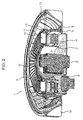
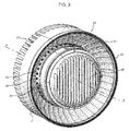
- the projector 20 illustrated in these figures also comprises a cylindrical body 21 of axis XX 'of external diameter 145 mm so that the projector is here of size PAR 46. It comprises a front face 22, through which the light beam is delivered by the projector, and an opposite rear face 23.
- the body 21 comprises an annular support 24 made in the form of a hollow cylinder around which is wound a printed circuit 25 comprising a set of electroluminescent diodes 26 arranged radially, that is to say oriented perpendicular to the axis XX ' of the body 21.
- the printed circuit 25 may comprise 40 light-emitting diodes 26 regularly distributed around the support 24.
- the printed circuit may be flexible. Alternatively, it may be non-flexible, being shaped to fit the diameter of the annular support 24.
- the body comprises a housing 27 delimited internally by the support 24, externally by a peripheral wall 28 and by a bottom 29.
- the bottom 29 comprises, in the vicinity of the support 24, a groove 30 in which are housed a set of juxtaposed parabolic reflector elements, such as 31, arranged in a ring and each placed opposite a diode 26 so each diode 26 is placed at the focus of a reflective element.
- annular mirror 32 transparent to the light is placed in the path of the beam reflected by the reflector.
- annular support which comprises a generally cylindrical wall 34 and a transverse end wall 35 which constitutes a radiator facilitating the dissipation of the heat generated by the LEDs.
- the annular support 24 is fixed to the body by screws, such as 36. It constitutes a bell under which is placed an electronic card 37 for supplying the diodes 26, itself connected to a conductor ply 38, so that this supply card 37 is also in heat exchange relation with the radiator 35.
- the body 21 is also provided, on its rear face 23, with a second radiator 39 which also contributes to the dissipation of the heat generated by the LEDs.
- radiator 35 on the front face 22 of the projector is advantageous insofar as this face is generally exposed to the outer elements and is therefore effectively cooled.
- the ring arrangement of the reflector elements and diodes makes it possible to densify the diodes and thus to create a projector of very high intensity and in a small footprint. It has notably been found that such a projector having a PAR 46 format makes it possible to obtain an intensity of the order of 450,000 to 600,000 candelas.
- the projector is described with reference to Figures 3 to 5 has a reflector consisting of 40 sectors of parabolic mirrors with a focal length of 4mm.
- the axes of the 40 mirrors are 47 mm from the main axis of the projector.
- Each Mirror area covers an angle of 9 °.
- the projector has 40 light-emitting diodes each arranged at the focus of one of the 40 mirror sectors.
- the reflector composed of the 40 sectors of mirrors has a diameter of 136 mm, a radius of 21 mm for each of the parabolas of revolution.
- Such a projector makes it possible to obtain an intensity peak of 600,000 candelas, a circular field of +/- 5 ° at 60,000 candelas.
- the flux in the useful field is 5200 lumens for 10800 lumens emitted, an optical efficiency of 48% considering a reflector having a reflection coefficient of 90%.
- the reduction of the front diameter of the projector obtained thanks to the particular arrangement of the diodes and reflector elements makes it possible, in the case of the use of a projector in an aircraft lighting system, to accommodate these projectors in the leading edge of the wings by having a transparent window of limited size.
- Reducing the size of the projector also makes it easier to mount a PAR 46 projector on board a helicopter to form a searchlight, while having performance similar to that of a PAR 64 projector.
- the first radiator 35 provided on the front face on the annular support 24 may be omitted.
- the space released in the center of the housing can then be used to install one or more other organs of execution of an additional function.
- the reflector elements 31 advantageously, parabolic mirrors whose focal length is adapted to use LEDs having an emitting zone of 0.5 to 4 mm 2 , will be advantageously provided. improves the luminous flux since such diodes generally have an improved efficiency. For example, diodes having a power of 1 to 10W may be used.
- the reflector elements 31 are not necessarily metallic because, thanks in particular to the presence of the annular support 24 which carries the radiator 35, these reflective elements 31 do not participate in the heat dissipation because they are not in contact with outside air. In this respect, for example, reflector elements 31 consisting of injected plastic mirrors coated with a reflective aluminum layer can be used, which allows a gain in terms of weight.
Landscapes
- Engineering & Computer Science (AREA)
- General Engineering & Computer Science (AREA)
- Aviation & Aerospace Engineering (AREA)
- Computer Security & Cryptography (AREA)
- Environmental & Geological Engineering (AREA)
- Physics & Mathematics (AREA)
- General Physics & Mathematics (AREA)
- Non-Portable Lighting Devices Or Systems Thereof (AREA)
- Arrangement Of Elements, Cooling, Sealing, Or The Like Of Lighting Devices (AREA)
- Led Device Packages (AREA)
- Optical Communication System (AREA)
Applications Claiming Priority (1)
| Application Number | Priority Date | Filing Date | Title |
|---|---|---|---|
| FR1554797A FR3036687B1 (fr) | 2015-05-28 | 2015-05-28 | Dispositif d'eclairage pour aeronef permettant l'integration en son centre de fonctions additionnelles |
Publications (2)
| Publication Number | Publication Date |
|---|---|
| EP3098505A1 true EP3098505A1 (de) | 2016-11-30 |
| EP3098505B1 EP3098505B1 (de) | 2018-05-16 |
Family
ID=53879651
Family Applications (1)
| Application Number | Title | Priority Date | Filing Date |
|---|---|---|---|
| EP16171344.1A Active EP3098505B1 (de) | 2015-05-28 | 2016-05-25 | Flugzeugleuchte und zentrale integration zusätzlichen funktionen |
Country Status (8)
| Country | Link |
|---|---|
| US (1) | US10246199B2 (de) |
| EP (1) | EP3098505B1 (de) |
| CN (1) | CN106195919A (de) |
| BR (1) | BR102016012075B1 (de) |
| CA (1) | CA2930392C (de) |
| ES (1) | ES2681509T3 (de) |
| FR (1) | FR3036687B1 (de) |
| RU (1) | RU2721431C2 (de) |
Families Citing this family (7)
| Publication number | Priority date | Publication date | Assignee | Title |
|---|---|---|---|---|
| EP3354971B1 (de) * | 2017-01-31 | 2021-06-30 | Marelli Automotive Lighting Italy S.p.A. | Beleuchtungsvorrichtung für mit led-beleuchtungsmodulen ausgestattete fahrzeuge |
| EP3403937B1 (de) * | 2017-05-19 | 2021-01-13 | Goodrich Lighting Systems GmbH | Flugzeugaussenlichteinheit |
| EP3473554B1 (de) * | 2017-10-23 | 2021-12-01 | Goodrich Lighting Systems GmbH | Flugzeugaussenlichteinheit |
| FR3090584B1 (fr) | 2018-12-21 | 2021-01-15 | Dassault Aviat | Système d’éclairage et de mesures d’un aéronef |
| EP3882161B1 (de) | 2020-03-20 | 2023-08-16 | Goodrich Lighting Systems GmbH & Co. KG | Hubschraubersuchlicht und verfahren zum betrieb eines hubschraubersuchlichts |
| EP4063278B1 (de) | 2021-03-25 | 2024-08-28 | Goodrich Lighting Systems GmbH & Co. KG | Antikollisionsleuchte für flugzeuge, flugzeug mit einer antikollisionsleuchte für flugzeuge und verfahren zum betreiben einer flugzeugantikollisionsleuchte |
| EP4082918B1 (de) * | 2021-04-29 | 2025-04-09 | Goodrich Lighting Systems GmbH & Co. KG | Flugzeugleuchtfeuer, flugzeug mit einem flugzeugleuchtfeuer und verfahren zur bestimmung des zustands eines flugzeugleuchtfeuers |
Citations (11)
| Publication number | Priority date | Publication date | Assignee | Title |
|---|---|---|---|---|
| EP1077344A2 (de) | 1999-08-16 | 2001-02-21 | FER Fahrzeugelektrik GmbH | Leuchte |
| WO2003095894A1 (en) | 2002-02-21 | 2003-11-20 | Whelen Engineering Company, Inc. | Led light assembly |
| US20060001384A1 (en) * | 2004-06-30 | 2006-01-05 | Industrial Technology Research Institute | LED lamp |
| EP1731423A1 (de) | 2005-06-06 | 2006-12-13 | Ece | Antikollisionsleuchte |
| EP2116756A1 (de) * | 2008-05-09 | 2009-11-11 | Illumina S.r.l. | Beleuchtungsvorrichtung |
| EP2131104A2 (de) | 2008-05-13 | 2009-12-09 | Honeywell International Inc. | Systeme und Verfahren für Leuchtdiodenflutlicht mit hoher Intensität |
| EP2450279A1 (de) | 2010-11-05 | 2012-05-09 | Sirio Panel S.P.A. | LED-Beleuchtungsvorrichtung eines Flugzeugs, insbesondere für Manöver beim Landen, Starten, Rollen und Suchen, sowie Flugzeug mit besagter Vorrichtung |
| EP2574837A2 (de) * | 2011-09-28 | 2013-04-03 | Goodrich Lighting Systems GmbH | Flugzeugscheinwerfer |
| WO2013094480A1 (ja) * | 2011-12-19 | 2013-06-27 | シャープ株式会社 | 照明装置、シーリングライト、バックライト、液晶表示装置、及びテレビジョン受信装置 |
| US20130249375A1 (en) * | 2012-03-21 | 2013-09-26 | George W. Panagotacos | Anti-icing solid state aircraft lamp assembly with defroster apparatus, system, and method |
| US20140199168A1 (en) * | 2013-01-11 | 2014-07-17 | Daniel S. Spiro | Integrated ceiling device with mechanical arrangement for a light source |
Family Cites Families (24)
| Publication number | Priority date | Publication date | Assignee | Title |
|---|---|---|---|---|
| US3732414A (en) * | 1971-03-19 | 1973-05-08 | C Franc | Portable illumination device |
| DE3723009A1 (de) * | 1987-07-11 | 1989-01-19 | Heraeus Gmbh W C | Operationsleuchte |
| TW402856B (en) * | 1996-12-26 | 2000-08-21 | Palite Corp | LED illuminator |
| US6068384A (en) * | 1998-04-07 | 2000-05-30 | Nsi Enterprises, Inc. | Lighting system |
| GB0117905D0 (en) * | 2001-07-23 | 2001-09-12 | Univ Bristol | An inducer of apoptosis |
| US20050146884A1 (en) * | 2004-01-07 | 2005-07-07 | Goodrich Hella Aerospace Lighting Systems Gmbh | Light, particularly a warning light, for a vehicle |
| US7327254B2 (en) * | 2005-02-02 | 2008-02-05 | Chen Kai-Po | Bulb with sensing function |
| US10539311B2 (en) * | 2008-04-14 | 2020-01-21 | Digital Lumens Incorporated | Sensor-based lighting methods, apparatus, and systems |
| US20100277916A1 (en) * | 2009-04-29 | 2010-11-04 | Hiroshi Kira | LED Light Module and Modular Lighting System |
| US8199029B2 (en) * | 2009-06-22 | 2012-06-12 | Kidde Technologies, Inc. | Combined smoke detector and lighting unit |
| US8123379B2 (en) * | 2009-06-24 | 2012-02-28 | Chen Kai-Po | Lighting device with sensor |
| CA2768777C (en) * | 2009-07-21 | 2017-11-28 | Cooper Technologies Company | Interfacing a light emitting diode (led) module to a heat sink assembly, a light reflector and electrical circuits |
| US8686623B2 (en) * | 2012-02-01 | 2014-04-01 | Switch Bulb Company, Inc. | Omni-directional channeling of liquids for passive convection in LED bulbs |
| EP2645517B1 (de) * | 2012-03-30 | 2017-07-19 | ABB Schweiz AG | Verbesserung der Zuverlässigkeit der Erkennung von Inselbildung in einem Stromverteilungsnetz |
| JP6137191B2 (ja) * | 2012-10-25 | 2017-05-31 | 旭硝子株式会社 | 車両用窓ガラスおよびその取付構造 |
| RU134286U1 (ru) * | 2013-04-05 | 2013-11-10 | Сергей Александрович Панин | Светодиодный источник белого света |
| JP6049559B2 (ja) * | 2013-07-04 | 2016-12-21 | 愛三工業株式会社 | 蒸発燃料処理装置 |
| TWM472161U (zh) * | 2013-09-18 | 2014-02-11 | Huang Tai Yin | 發光二極體燈具 |
| CN203560795U (zh) * | 2013-12-02 | 2014-04-23 | 广东凯西欧照明有限公司 | 止动环限位的双圆旋转调焦天花灯 |
| CA2875014A1 (en) * | 2013-12-17 | 2015-06-17 | Ephesus Lighting, Inc. | Lens structure for high intensity led fixture |
| CN203892962U (zh) * | 2014-05-28 | 2014-10-22 | 上海开腾信号设备有限公司 | 一种中小直径高光强led环射信号灯 |
| RU148487U1 (ru) * | 2014-08-27 | 2014-12-10 | Общество с ограниченной ответственностью "ДИОДОСВЕТ" (ООО "ДИОДОСВЕТ") | Светильник светодиодный |
| CN204227265U (zh) * | 2014-10-31 | 2015-03-25 | 安徽华夏显示技术股份有限公司 | 一种新型hid与led互补型飞机着陆滑行灯 |
| CN104443416B (zh) * | 2014-12-29 | 2016-06-01 | 马鞍山市赛迪智能科技有限公司 | 无人机留空照明系统 |
-
2015
- 2015-05-28 FR FR1554797A patent/FR3036687B1/fr not_active Expired - Fee Related
-
2016
- 2016-05-17 CA CA2930392A patent/CA2930392C/fr active Active
- 2016-05-24 RU RU2016120006A patent/RU2721431C2/ru active
- 2016-05-25 ES ES16171344.1T patent/ES2681509T3/es active Active
- 2016-05-25 EP EP16171344.1A patent/EP3098505B1/de active Active
- 2016-05-27 CN CN201610365833.7A patent/CN106195919A/zh active Pending
- 2016-05-27 US US15/167,575 patent/US10246199B2/en active Active
- 2016-05-27 BR BR102016012075-6A patent/BR102016012075B1/pt active IP Right Grant
Patent Citations (11)
| Publication number | Priority date | Publication date | Assignee | Title |
|---|---|---|---|---|
| EP1077344A2 (de) | 1999-08-16 | 2001-02-21 | FER Fahrzeugelektrik GmbH | Leuchte |
| WO2003095894A1 (en) | 2002-02-21 | 2003-11-20 | Whelen Engineering Company, Inc. | Led light assembly |
| US20060001384A1 (en) * | 2004-06-30 | 2006-01-05 | Industrial Technology Research Institute | LED lamp |
| EP1731423A1 (de) | 2005-06-06 | 2006-12-13 | Ece | Antikollisionsleuchte |
| EP2116756A1 (de) * | 2008-05-09 | 2009-11-11 | Illumina S.r.l. | Beleuchtungsvorrichtung |
| EP2131104A2 (de) | 2008-05-13 | 2009-12-09 | Honeywell International Inc. | Systeme und Verfahren für Leuchtdiodenflutlicht mit hoher Intensität |
| EP2450279A1 (de) | 2010-11-05 | 2012-05-09 | Sirio Panel S.P.A. | LED-Beleuchtungsvorrichtung eines Flugzeugs, insbesondere für Manöver beim Landen, Starten, Rollen und Suchen, sowie Flugzeug mit besagter Vorrichtung |
| EP2574837A2 (de) * | 2011-09-28 | 2013-04-03 | Goodrich Lighting Systems GmbH | Flugzeugscheinwerfer |
| WO2013094480A1 (ja) * | 2011-12-19 | 2013-06-27 | シャープ株式会社 | 照明装置、シーリングライト、バックライト、液晶表示装置、及びテレビジョン受信装置 |
| US20130249375A1 (en) * | 2012-03-21 | 2013-09-26 | George W. Panagotacos | Anti-icing solid state aircraft lamp assembly with defroster apparatus, system, and method |
| US20140199168A1 (en) * | 2013-01-11 | 2014-07-17 | Daniel S. Spiro | Integrated ceiling device with mechanical arrangement for a light source |
Also Published As
| Publication number | Publication date |
|---|---|
| BR102016012075B1 (pt) | 2022-11-16 |
| FR3036687B1 (fr) | 2019-01-25 |
| US10246199B2 (en) | 2019-04-02 |
| CN106195919A (zh) | 2016-12-07 |
| CA2930392A1 (fr) | 2016-11-28 |
| RU2016120006A3 (de) | 2019-09-27 |
| ES2681509T3 (es) | 2018-09-13 |
| EP3098505B1 (de) | 2018-05-16 |
| US20160347474A1 (en) | 2016-12-01 |
| CA2930392C (fr) | 2023-06-27 |
| BR102016012075A2 (pt) | 2016-11-29 |
| RU2721431C2 (ru) | 2020-05-19 |
| RU2016120006A (ru) | 2017-11-29 |
| FR3036687A1 (fr) | 2016-12-02 |
Similar Documents
| Publication | Publication Date | Title |
|---|---|---|
| EP3098505B1 (de) | Flugzeugleuchte und zentrale integration zusätzlichen funktionen | |
| EP1731423B1 (de) | Antikollisionsleuchte | |
| FR2981428A1 (fr) | Projecteur d'atterrissage a diode electroluminescente | |
| FR2907191A1 (fr) | Eclairage encastre pour vehicule automobile ou avion. | |
| EP3529156B1 (de) | Multifunktionelles flugzeuglandelicht mit statischer funktionsumschaltung | |
| EP3087308B1 (de) | Sphärische beleuchtungsvorrichtung | |
| CA2901937C (fr) | Dispositif optique pour projecteur d'eclairage et/ou de signalisation pour aeronef et projecteur comprenant un tel dispositif optique | |
| FR2950670A1 (fr) | Dispositif d'eclairage indirect d'une surface a diodes electroluminescentes | |
| CA2902962C (fr) | Projecteur d'eclairage et/ou de signalisation exterieur et systeme d'eclairage et/ou de signalisation correspondant | |
| EP1488954B1 (de) | Beleuchtungs- oder Signalisierungssystem für Fahrzeuge | |
| FR2992050A1 (fr) | Dispositif d'eclairage de piste a del et optique specifique dediee. | |
| EP3230651B1 (de) | System zur visuellen signalisierung | |
| EP3214661A1 (de) | Lichtquelle mit halbleitern zum ausstrahlen und empfangen von lichtstrahlen, und leuchtsystem, das eine solche quelle umfasst | |
| EP0694793B1 (de) | Verfahren und Vorrichtung zum Erkennen eines besonderen Elementes in der Dunkelheit | |
| CA3041001C (fr) | Projecteur de piste multifonctions a commutation de fonctions statique pour aeronef | |
| EP3374689B1 (de) | Beleuchtungsvorrichtung für ein kraftfahrzeug | |
| FR3048656A3 (fr) | Dispositif d'eclairage d'urgence pour vehicules | |
| FR3013102A1 (fr) | Dispositif lumineux, module d'eclairage et/ou de signalisation et vehicule automobile | |
| FR3119663A1 (fr) | Source lumineuse pour la signalisation d’un véhicule automobile | |
| FR3087520A1 (fr) | Module lumineux assurant deux fonctions photometriques presentant des signatures lumineuses distinctes | |
| FR3054297A1 (fr) | Dispositif d'eclairage pour vehicule automobile |
Legal Events
| Date | Code | Title | Description |
|---|---|---|---|
| PUAI | Public reference made under article 153(3) epc to a published international application that has entered the european phase |
Free format text: ORIGINAL CODE: 0009012 |
|
| AK | Designated contracting states |
Kind code of ref document: A1 Designated state(s): AL AT BE BG CH CY CZ DE DK EE ES FI FR GB GR HR HU IE IS IT LI LT LU LV MC MK MT NL NO PL PT RO RS SE SI SK SM TR |
|
| AX | Request for extension of the european patent |
Extension state: BA ME |
|
| 17P | Request for examination filed |
Effective date: 20170307 |
|
| RBV | Designated contracting states (corrected) |
Designated state(s): AL AT BE BG CH CY CZ DE DK EE ES FI FR GB GR HR HU IE IS IT LI LT LU LV MC MK MT NL NO PL PT RO RS SE SI SK SM TR |
|
| 17Q | First examination report despatched |
Effective date: 20170620 |
|
| GRAP | Despatch of communication of intention to grant a patent |
Free format text: ORIGINAL CODE: EPIDOSNIGR1 |
|
| INTG | Intention to grant announced |
Effective date: 20171215 |
|
| GRAS | Grant fee paid |
Free format text: ORIGINAL CODE: EPIDOSNIGR3 |
|
| GRAA | (expected) grant |
Free format text: ORIGINAL CODE: 0009210 |
|
| AK | Designated contracting states |
Kind code of ref document: B1 Designated state(s): AL AT BE BG CH CY CZ DE DK EE ES FI FR GB GR HR HU IE IS IT LI LT LU LV MC MK MT NL NO PL PT RO RS SE SI SK SM TR |
|
| REG | Reference to a national code |
Ref country code: GB Ref legal event code: FG4D Free format text: NOT ENGLISH |
|
| REG | Reference to a national code |
Ref country code: CH Ref legal event code: EP |
|
| REG | Reference to a national code |
Ref country code: IE Ref legal event code: FG4D Free format text: LANGUAGE OF EP DOCUMENT: FRENCH |
|
| REG | Reference to a national code |
Ref country code: DE Ref legal event code: R096 Ref document number: 602016003062 Country of ref document: DE |
|
| REG | Reference to a national code |
Ref country code: AT Ref legal event code: REF Ref document number: 999927 Country of ref document: AT Kind code of ref document: T Effective date: 20180615 |
|
| REG | Reference to a national code |
Ref country code: FR Ref legal event code: PLFP Year of fee payment: 3 |
|
| REG | Reference to a national code |
Ref country code: ES Ref legal event code: FG2A Ref document number: 2681509 Country of ref document: ES Kind code of ref document: T3 Effective date: 20180913 |
|
| REG | Reference to a national code |
Ref country code: NL Ref legal event code: MP Effective date: 20180516 |
|
| REG | Reference to a national code |
Ref country code: LT Ref legal event code: MG4D |
|
| PG25 | Lapsed in a contracting state [announced via postgrant information from national office to epo] |
Ref country code: LT Free format text: LAPSE BECAUSE OF FAILURE TO SUBMIT A TRANSLATION OF THE DESCRIPTION OR TO PAY THE FEE WITHIN THE PRESCRIBED TIME-LIMIT Effective date: 20180516 Ref country code: NO Free format text: LAPSE BECAUSE OF FAILURE TO SUBMIT A TRANSLATION OF THE DESCRIPTION OR TO PAY THE FEE WITHIN THE PRESCRIBED TIME-LIMIT Effective date: 20180816 Ref country code: BG Free format text: LAPSE BECAUSE OF FAILURE TO SUBMIT A TRANSLATION OF THE DESCRIPTION OR TO PAY THE FEE WITHIN THE PRESCRIBED TIME-LIMIT Effective date: 20180816 Ref country code: SE Free format text: LAPSE BECAUSE OF FAILURE TO SUBMIT A TRANSLATION OF THE DESCRIPTION OR TO PAY THE FEE WITHIN THE PRESCRIBED TIME-LIMIT Effective date: 20180516 Ref country code: FI Free format text: LAPSE BECAUSE OF FAILURE TO SUBMIT A TRANSLATION OF THE DESCRIPTION OR TO PAY THE FEE WITHIN THE PRESCRIBED TIME-LIMIT Effective date: 20180516 |
|
| PG25 | Lapsed in a contracting state [announced via postgrant information from national office to epo] |
Ref country code: GR Free format text: LAPSE BECAUSE OF FAILURE TO SUBMIT A TRANSLATION OF THE DESCRIPTION OR TO PAY THE FEE WITHIN THE PRESCRIBED TIME-LIMIT Effective date: 20180817 Ref country code: RS Free format text: LAPSE BECAUSE OF FAILURE TO SUBMIT A TRANSLATION OF THE DESCRIPTION OR TO PAY THE FEE WITHIN THE PRESCRIBED TIME-LIMIT Effective date: 20180516 Ref country code: LV Free format text: LAPSE BECAUSE OF FAILURE TO SUBMIT A TRANSLATION OF THE DESCRIPTION OR TO PAY THE FEE WITHIN THE PRESCRIBED TIME-LIMIT Effective date: 20180516 Ref country code: HR Free format text: LAPSE BECAUSE OF FAILURE TO SUBMIT A TRANSLATION OF THE DESCRIPTION OR TO PAY THE FEE WITHIN THE PRESCRIBED TIME-LIMIT Effective date: 20180516 Ref country code: NL Free format text: LAPSE BECAUSE OF FAILURE TO SUBMIT A TRANSLATION OF THE DESCRIPTION OR TO PAY THE FEE WITHIN THE PRESCRIBED TIME-LIMIT Effective date: 20180516 |
|
| REG | Reference to a national code |
Ref country code: AT Ref legal event code: MK05 Ref document number: 999927 Country of ref document: AT Kind code of ref document: T Effective date: 20180516 |
|
| REG | Reference to a national code |
Ref country code: BE Ref legal event code: MM Effective date: 20180531 |
|
| PG25 | Lapsed in a contracting state [announced via postgrant information from national office to epo] |
Ref country code: CZ Free format text: LAPSE BECAUSE OF FAILURE TO SUBMIT A TRANSLATION OF THE DESCRIPTION OR TO PAY THE FEE WITHIN THE PRESCRIBED TIME-LIMIT Effective date: 20180516 Ref country code: SK Free format text: LAPSE BECAUSE OF FAILURE TO SUBMIT A TRANSLATION OF THE DESCRIPTION OR TO PAY THE FEE WITHIN THE PRESCRIBED TIME-LIMIT Effective date: 20180516 Ref country code: PL Free format text: LAPSE BECAUSE OF FAILURE TO SUBMIT A TRANSLATION OF THE DESCRIPTION OR TO PAY THE FEE WITHIN THE PRESCRIBED TIME-LIMIT Effective date: 20180516 Ref country code: AT Free format text: LAPSE BECAUSE OF FAILURE TO SUBMIT A TRANSLATION OF THE DESCRIPTION OR TO PAY THE FEE WITHIN THE PRESCRIBED TIME-LIMIT Effective date: 20180516 Ref country code: DK Free format text: LAPSE BECAUSE OF FAILURE TO SUBMIT A TRANSLATION OF THE DESCRIPTION OR TO PAY THE FEE WITHIN THE PRESCRIBED TIME-LIMIT Effective date: 20180516 Ref country code: RO Free format text: LAPSE BECAUSE OF FAILURE TO SUBMIT A TRANSLATION OF THE DESCRIPTION OR TO PAY THE FEE WITHIN THE PRESCRIBED TIME-LIMIT Effective date: 20180516 Ref country code: EE Free format text: LAPSE BECAUSE OF FAILURE TO SUBMIT A TRANSLATION OF THE DESCRIPTION OR TO PAY THE FEE WITHIN THE PRESCRIBED TIME-LIMIT Effective date: 20180516 |
|
| REG | Reference to a national code |
Ref country code: DE Ref legal event code: R097 Ref document number: 602016003062 Country of ref document: DE |
|
| REG | Reference to a national code |
Ref country code: IE Ref legal event code: MM4A |
|
| PG25 | Lapsed in a contracting state [announced via postgrant information from national office to epo] |
Ref country code: SM Free format text: LAPSE BECAUSE OF FAILURE TO SUBMIT A TRANSLATION OF THE DESCRIPTION OR TO PAY THE FEE WITHIN THE PRESCRIBED TIME-LIMIT Effective date: 20180516 |
|
| PLBE | No opposition filed within time limit |
Free format text: ORIGINAL CODE: 0009261 |
|
| STAA | Information on the status of an ep patent application or granted ep patent |
Free format text: STATUS: NO OPPOSITION FILED WITHIN TIME LIMIT |
|
| PG25 | Lapsed in a contracting state [announced via postgrant information from national office to epo] |
Ref country code: MC Free format text: LAPSE BECAUSE OF FAILURE TO SUBMIT A TRANSLATION OF THE DESCRIPTION OR TO PAY THE FEE WITHIN THE PRESCRIBED TIME-LIMIT Effective date: 20180516 Ref country code: LU Free format text: LAPSE BECAUSE OF NON-PAYMENT OF DUE FEES Effective date: 20180525 |
|
| 26N | No opposition filed |
Effective date: 20190219 |
|
| PG25 | Lapsed in a contracting state [announced via postgrant information from national office to epo] |
Ref country code: IE Free format text: LAPSE BECAUSE OF NON-PAYMENT OF DUE FEES Effective date: 20180525 |
|
| PG25 | Lapsed in a contracting state [announced via postgrant information from national office to epo] |
Ref country code: BE Free format text: LAPSE BECAUSE OF NON-PAYMENT OF DUE FEES Effective date: 20180531 Ref country code: SI Free format text: LAPSE BECAUSE OF FAILURE TO SUBMIT A TRANSLATION OF THE DESCRIPTION OR TO PAY THE FEE WITHIN THE PRESCRIBED TIME-LIMIT Effective date: 20180516 |
|
| PG25 | Lapsed in a contracting state [announced via postgrant information from national office to epo] |
Ref country code: AL Free format text: LAPSE BECAUSE OF FAILURE TO SUBMIT A TRANSLATION OF THE DESCRIPTION OR TO PAY THE FEE WITHIN THE PRESCRIBED TIME-LIMIT Effective date: 20180516 |
|
| REG | Reference to a national code |
Ref country code: CH Ref legal event code: PL |
|
| PG25 | Lapsed in a contracting state [announced via postgrant information from national office to epo] |
Ref country code: MT Free format text: LAPSE BECAUSE OF FAILURE TO SUBMIT A TRANSLATION OF THE DESCRIPTION OR TO PAY THE FEE WITHIN THE PRESCRIBED TIME-LIMIT Effective date: 20180516 Ref country code: CH Free format text: LAPSE BECAUSE OF NON-PAYMENT OF DUE FEES Effective date: 20190531 Ref country code: LI Free format text: LAPSE BECAUSE OF NON-PAYMENT OF DUE FEES Effective date: 20190531 |
|
| PG25 | Lapsed in a contracting state [announced via postgrant information from national office to epo] |
Ref country code: TR Free format text: LAPSE BECAUSE OF FAILURE TO SUBMIT A TRANSLATION OF THE DESCRIPTION OR TO PAY THE FEE WITHIN THE PRESCRIBED TIME-LIMIT Effective date: 20180516 |
|
| PG25 | Lapsed in a contracting state [announced via postgrant information from national office to epo] |
Ref country code: PT Free format text: LAPSE BECAUSE OF FAILURE TO SUBMIT A TRANSLATION OF THE DESCRIPTION OR TO PAY THE FEE WITHIN THE PRESCRIBED TIME-LIMIT Effective date: 20180516 |
|
| PG25 | Lapsed in a contracting state [announced via postgrant information from national office to epo] |
Ref country code: MK Free format text: LAPSE BECAUSE OF NON-PAYMENT OF DUE FEES Effective date: 20180516 Ref country code: HU Free format text: LAPSE BECAUSE OF FAILURE TO SUBMIT A TRANSLATION OF THE DESCRIPTION OR TO PAY THE FEE WITHIN THE PRESCRIBED TIME-LIMIT; INVALID AB INITIO Effective date: 20160525 Ref country code: CY Free format text: LAPSE BECAUSE OF FAILURE TO SUBMIT A TRANSLATION OF THE DESCRIPTION OR TO PAY THE FEE WITHIN THE PRESCRIBED TIME-LIMIT Effective date: 20180516 |
|
| PG25 | Lapsed in a contracting state [announced via postgrant information from national office to epo] |
Ref country code: IS Free format text: LAPSE BECAUSE OF FAILURE TO SUBMIT A TRANSLATION OF THE DESCRIPTION OR TO PAY THE FEE WITHIN THE PRESCRIBED TIME-LIMIT Effective date: 20180916 |
|
| GBPC | Gb: european patent ceased through non-payment of renewal fee |
Effective date: 20200525 |
|
| PG25 | Lapsed in a contracting state [announced via postgrant information from national office to epo] |
Ref country code: GB Free format text: LAPSE BECAUSE OF NON-PAYMENT OF DUE FEES Effective date: 20200525 |
|
| REG | Reference to a national code |
Ref country code: ES Ref legal event code: PC2A Owner name: SAFRAN ELECTRONICS & DEFENSE COCKPIT SOLUTIONS Effective date: 20210517 |
|
| REG | Reference to a national code |
Ref country code: DE Ref legal event code: R081 Ref document number: 602016003062 Country of ref document: DE Owner name: SAFRAN ELECTRONICS & DEFENSE COCKPIT SOLUTIONS, FR Free format text: FORMER OWNER: ZODIAC AERO ELECTRIC, MONTREUIL, FR |
|
| PGFP | Annual fee paid to national office [announced via postgrant information from national office to epo] |
Ref country code: DE Payment date: 20250519 Year of fee payment: 10 |
|
| PGFP | Annual fee paid to national office [announced via postgrant information from national office to epo] |
Ref country code: ES Payment date: 20250616 Year of fee payment: 10 |
|
| PGFP | Annual fee paid to national office [announced via postgrant information from national office to epo] |
Ref country code: IT Payment date: 20250530 Year of fee payment: 10 |
|
| PGFP | Annual fee paid to national office [announced via postgrant information from national office to epo] |
Ref country code: FR Payment date: 20250526 Year of fee payment: 10 |