EP3098511B1 - Procédé de réduction des oxydes d'azote et du monoxyde de carbone à partir de gaz de carneau et réglage de combustion correspondante - Google Patents
Procédé de réduction des oxydes d'azote et du monoxyde de carbone à partir de gaz de carneau et réglage de combustion correspondante Download PDFInfo
- Publication number
- EP3098511B1 EP3098511B1 EP16165426.4A EP16165426A EP3098511B1 EP 3098511 B1 EP3098511 B1 EP 3098511B1 EP 16165426 A EP16165426 A EP 16165426A EP 3098511 B1 EP3098511 B1 EP 3098511B1
- Authority
- EP
- European Patent Office
- Prior art keywords
- inlet flow
- amount
- fuel
- catalytic
- way
- Prior art date
- Legal status (The legal status is an assumption and is not a legal conclusion. Google has not performed a legal analysis and makes no representation as to the accuracy of the status listed.)
- Active
Links
Images


Classifications
-
- F—MECHANICAL ENGINEERING; LIGHTING; HEATING; WEAPONS; BLASTING
- F23—COMBUSTION APPARATUS; COMBUSTION PROCESSES
- F23J—REMOVAL OR TREATMENT OF COMBUSTION PRODUCTS OR COMBUSTION RESIDUES; FLUES
- F23J15/00—Arrangements of devices for treating smoke or fumes
- F23J15/02—Arrangements of devices for treating smoke or fumes of purifiers, e.g. for removing noxious material
-
- F—MECHANICAL ENGINEERING; LIGHTING; HEATING; WEAPONS; BLASTING
- F23—COMBUSTION APPARATUS; COMBUSTION PROCESSES
- F23D—BURNERS
- F23D14/00—Burners for combustion of a gas, e.g. of a gas stored under pressure as a liquid
- F23D14/46—Details
-
- B—PERFORMING OPERATIONS; TRANSPORTING
- B01—PHYSICAL OR CHEMICAL PROCESSES OR APPARATUS IN GENERAL
- B01D—SEPARATION
- B01D53/00—Separation of gases or vapours; Recovering vapours of volatile solvents from gases; Chemical or biological purification of waste gases, e.g. engine exhaust gases, smoke, fumes, flue gases, aerosols
- B01D53/34—Chemical or biological purification of waste gases
- B01D53/74—General processes for purification of waste gases; Apparatus or devices specially adapted therefor
- B01D53/86—Catalytic processes
- B01D53/8621—Removing nitrogen compounds
- B01D53/8625—Nitrogen oxides
-
- B—PERFORMING OPERATIONS; TRANSPORTING
- B01—PHYSICAL OR CHEMICAL PROCESSES OR APPARATUS IN GENERAL
- B01D—SEPARATION
- B01D53/00—Separation of gases or vapours; Recovering vapours of volatile solvents from gases; Chemical or biological purification of waste gases, e.g. engine exhaust gases, smoke, fumes, flue gases, aerosols
- B01D53/34—Chemical or biological purification of waste gases
- B01D53/74—General processes for purification of waste gases; Apparatus or devices specially adapted therefor
- B01D53/86—Catalytic processes
- B01D53/864—Removing carbon monoxide or hydrocarbons
-
- F—MECHANICAL ENGINEERING; LIGHTING; HEATING; WEAPONS; BLASTING
- F01—MACHINES OR ENGINES IN GENERAL; ENGINE PLANTS IN GENERAL; STEAM ENGINES
- F01N—GAS-FLOW SILENCERS OR EXHAUST APPARATUS FOR MACHINES OR ENGINES IN GENERAL; GAS-FLOW SILENCERS OR EXHAUST APPARATUS FOR INTERNAL-COMBUSTION ENGINES
- F01N3/00—Exhaust or silencing apparatus having means for purifying, rendering innocuous, or otherwise treating exhaust
- F01N3/08—Exhaust or silencing apparatus having means for purifying, rendering innocuous, or otherwise treating exhaust for rendering innocuous
- F01N3/10—Exhaust or silencing apparatus having means for purifying, rendering innocuous, or otherwise treating exhaust for rendering innocuous by thermal or catalytic conversion of noxious components of exhaust
- F01N3/101—Three-way catalysts
-
- F—MECHANICAL ENGINEERING; LIGHTING; HEATING; WEAPONS; BLASTING
- F23—COMBUSTION APPARATUS; COMBUSTION PROCESSES
- F23D—BURNERS
- F23D11/00—Burners using a direct spraying action of liquid droplets or vaporised liquid into the combustion space
- F23D11/36—Details
-
- F—MECHANICAL ENGINEERING; LIGHTING; HEATING; WEAPONS; BLASTING
- F23—COMBUSTION APPARATUS; COMBUSTION PROCESSES
- F23D—BURNERS
- F23D14/00—Burners for combustion of a gas, e.g. of a gas stored under pressure as a liquid
- F23D14/46—Details
- F23D14/60—Devices for simultaneous control of gas and combustion air
-
- F—MECHANICAL ENGINEERING; LIGHTING; HEATING; WEAPONS; BLASTING
- F23—COMBUSTION APPARATUS; COMBUSTION PROCESSES
- F23D—BURNERS
- F23D17/00—Burners for combustion simultaneously or alternately of gaseous or liquid or pulverulent fuel
- F23D17/002—Burners for combustion simultaneously or alternately of gaseous or liquid or pulverulent fuel gaseous or liquid fuel
-
- F—MECHANICAL ENGINEERING; LIGHTING; HEATING; WEAPONS; BLASTING
- F23—COMBUSTION APPARATUS; COMBUSTION PROCESSES
- F23N—REGULATING OR CONTROLLING COMBUSTION
- F23N1/00—Regulating fuel supply
- F23N1/002—Regulating fuel supply using electronic means
-
- F—MECHANICAL ENGINEERING; LIGHTING; HEATING; WEAPONS; BLASTING
- F23—COMBUSTION APPARATUS; COMBUSTION PROCESSES
- F23N—REGULATING OR CONTROLLING COMBUSTION
- F23N1/00—Regulating fuel supply
- F23N1/02—Regulating fuel supply conjointly with air supply
- F23N1/022—Regulating fuel supply conjointly with air supply using electronic means
-
- F—MECHANICAL ENGINEERING; LIGHTING; HEATING; WEAPONS; BLASTING
- F23—COMBUSTION APPARATUS; COMBUSTION PROCESSES
- F23N—REGULATING OR CONTROLLING COMBUSTION
- F23N3/00—Regulating air supply or draught
- F23N3/08—Regulating air supply or draught by power-assisted systems
- F23N3/082—Regulating air supply or draught by power-assisted systems using electronic means
-
- F—MECHANICAL ENGINEERING; LIGHTING; HEATING; WEAPONS; BLASTING
- F23—COMBUSTION APPARATUS; COMBUSTION PROCESSES
- F23N—REGULATING OR CONTROLLING COMBUSTION
- F23N5/00—Systems for controlling combustion
- F23N5/003—Systems for controlling combustion using detectors sensitive to combustion gas properties
- F23N5/006—Systems for controlling combustion using detectors sensitive to combustion gas properties the detector being sensitive to oxygen
-
- F—MECHANICAL ENGINEERING; LIGHTING; HEATING; WEAPONS; BLASTING
- F01—MACHINES OR ENGINES IN GENERAL; ENGINE PLANTS IN GENERAL; STEAM ENGINES
- F01N—GAS-FLOW SILENCERS OR EXHAUST APPARATUS FOR MACHINES OR ENGINES IN GENERAL; GAS-FLOW SILENCERS OR EXHAUST APPARATUS FOR INTERNAL-COMBUSTION ENGINES
- F01N2560/00—Exhaust systems with means for detecting or measuring exhaust gas components or characteristics
- F01N2560/02—Exhaust systems with means for detecting or measuring exhaust gas components or characteristics the means being an exhaust gas sensor
- F01N2560/022—Exhaust systems with means for detecting or measuring exhaust gas components or characteristics the means being an exhaust gas sensor for measuring or detecting CO or CO2
-
- F—MECHANICAL ENGINEERING; LIGHTING; HEATING; WEAPONS; BLASTING
- F01—MACHINES OR ENGINES IN GENERAL; ENGINE PLANTS IN GENERAL; STEAM ENGINES
- F01N—GAS-FLOW SILENCERS OR EXHAUST APPARATUS FOR MACHINES OR ENGINES IN GENERAL; GAS-FLOW SILENCERS OR EXHAUST APPARATUS FOR INTERNAL-COMBUSTION ENGINES
- F01N2560/00—Exhaust systems with means for detecting or measuring exhaust gas components or characteristics
- F01N2560/02—Exhaust systems with means for detecting or measuring exhaust gas components or characteristics the means being an exhaust gas sensor
- F01N2560/025—Exhaust systems with means for detecting or measuring exhaust gas components or characteristics the means being an exhaust gas sensor for measuring or detecting O2, e.g. lambda sensors
-
- F—MECHANICAL ENGINEERING; LIGHTING; HEATING; WEAPONS; BLASTING
- F01—MACHINES OR ENGINES IN GENERAL; ENGINE PLANTS IN GENERAL; STEAM ENGINES
- F01N—GAS-FLOW SILENCERS OR EXHAUST APPARATUS FOR MACHINES OR ENGINES IN GENERAL; GAS-FLOW SILENCERS OR EXHAUST APPARATUS FOR INTERNAL-COMBUSTION ENGINES
- F01N2560/00—Exhaust systems with means for detecting or measuring exhaust gas components or characteristics
- F01N2560/02—Exhaust systems with means for detecting or measuring exhaust gas components or characteristics the means being an exhaust gas sensor
- F01N2560/026—Exhaust systems with means for detecting or measuring exhaust gas components or characteristics the means being an exhaust gas sensor for measuring or detecting NOx
-
- F—MECHANICAL ENGINEERING; LIGHTING; HEATING; WEAPONS; BLASTING
- F01—MACHINES OR ENGINES IN GENERAL; ENGINE PLANTS IN GENERAL; STEAM ENGINES
- F01N—GAS-FLOW SILENCERS OR EXHAUST APPARATUS FOR MACHINES OR ENGINES IN GENERAL; GAS-FLOW SILENCERS OR EXHAUST APPARATUS FOR INTERNAL-COMBUSTION ENGINES
- F01N2590/00—Exhaust or silencing apparatus adapted to particular use, e.g. for military applications, airplanes, submarines
- F01N2590/10—Exhaust or silencing apparatus adapted to particular use, e.g. for military applications, airplanes, submarines for stationary applications
-
- F—MECHANICAL ENGINEERING; LIGHTING; HEATING; WEAPONS; BLASTING
- F23—COMBUSTION APPARATUS; COMBUSTION PROCESSES
- F23D—BURNERS
- F23D2208/00—Control devices associated with burners
- F23D2208/005—Controlling air supply in radiant gas burners
-
- F—MECHANICAL ENGINEERING; LIGHTING; HEATING; WEAPONS; BLASTING
- F23—COMBUSTION APPARATUS; COMBUSTION PROCESSES
- F23J—REMOVAL OR TREATMENT OF COMBUSTION PRODUCTS OR COMBUSTION RESIDUES; FLUES
- F23J2215/00—Preventing emissions
- F23J2215/10—Nitrogen; Compounds thereof
- F23J2215/101—Nitrous oxide (N2O)
-
- F—MECHANICAL ENGINEERING; LIGHTING; HEATING; WEAPONS; BLASTING
- F23—COMBUSTION APPARATUS; COMBUSTION PROCESSES
- F23J—REMOVAL OR TREATMENT OF COMBUSTION PRODUCTS OR COMBUSTION RESIDUES; FLUES
- F23J2215/00—Preventing emissions
- F23J2215/40—Carbon monoxide
-
- F—MECHANICAL ENGINEERING; LIGHTING; HEATING; WEAPONS; BLASTING
- F23—COMBUSTION APPARATUS; COMBUSTION PROCESSES
- F23J—REMOVAL OR TREATMENT OF COMBUSTION PRODUCTS OR COMBUSTION RESIDUES; FLUES
- F23J2219/00—Treatment devices
- F23J2219/10—Catalytic reduction devices
-
- Y—GENERAL TAGGING OF NEW TECHNOLOGICAL DEVELOPMENTS; GENERAL TAGGING OF CROSS-SECTIONAL TECHNOLOGIES SPANNING OVER SEVERAL SECTIONS OF THE IPC; TECHNICAL SUBJECTS COVERED BY FORMER USPC CROSS-REFERENCE ART COLLECTIONS [XRACs] AND DIGESTS
- Y02—TECHNOLOGIES OR APPLICATIONS FOR MITIGATION OR ADAPTATION AGAINST CLIMATE CHANGE
- Y02T—CLIMATE CHANGE MITIGATION TECHNOLOGIES RELATED TO TRANSPORTATION
- Y02T10/00—Road transport of goods or passengers
- Y02T10/10—Internal combustion engine [ICE] based vehicles
- Y02T10/12—Improving ICE efficiencies
Definitions
- the invention relates to a method as set forth in the claim 1 for reducing nitrogen oxide(s) and carbon monoxide from flue gases of an industrial burner which is intended for a gaseous and/or liquid fuel.
- the invention relates further to burner automation according to claim 16, which can be used for carrying out the method of the invention.
- One generally known industrial burner model which is intended for gaseous and/or liquid fuels, comprises in connection with the windbox a fuel supply conduit for the combustion head and opening to the combustion head, as well as a combustion air supply conduit opening into the windbox.
- the windbox is associated with a combustion chamber, such as a boiler, which opens into a flue gas conduit.
- the burner operation is controlled by burner automation, comprising measuring instruments which include in particular a lambda sensor that measures the amount of residual oxygen in flue gases.
- a lambda-controlled burner with flue gas catalyst is known from US 2009/0325112 .
- One possibility of reducing the amount of emissions is to use catalytic post-combustion known from the Applicant's WO application No. 2014/154931 in connection with the above-described burner by placing a catalytic converter in a combustion chamber, such as a boiler or flue gas conduit, present in association with the burner.
- the fuel is pre-combusted partially in at least one thermal pre-combustion zone of the burner and thereafter the post-combustion of pre-combustion-generated gases is carried out in at least one post-combustion zone provided with a catalytic converter for burning the pre-combustion-generated gases, for the reduction of pre-combustion-generated NOx's, and/or for the oxidation of hydrocarbon and carbon monoxide emissions.
- the post-combustion is conducted in at least one catalytic zone.
- the apparatus comprises a thermal burner which is supplied with a liquid or gaseous fuel, and the apparatus is further provided with at least one catalytic converter for the reduction of NOx's present in flue gases generated in thermal combustion, as well as for the oxidation of hydrocarbon and carbon monoxide emissions.
- the oxygen content of flue gases shall vary roughly +/- 1%, which corresponds to about 10% of the amount of combustion air.
- the excess air of a burner can also be adjusted to a lower level by a feedback of the oxygen measurement conducted from flue gases.
- oxygen measurement the combustion air or fuel of a burner is controlled by burner automation so as to maintain the oxygen content of flue gas at about 2-3%.
- One important further objective of the invention relates to a method, which enables the amounts of air and fuel for a burner to be adjusted in a (thermal) combustion process of the burner so as to reach low residual oxygen prior to a catalytic zone.
- the term "industrial burner” in this application refers to an apparatus, which is capable of being connected to a combustion chamber such as a boiler and which comprises all devices needed for a combustion operation and its monitoring. These comprise fuel and air mixers, air supply means, including air blowers that can be incorporated in the burner (a so-called monoblock burner) or separate (a so-called duoblock burner).
- the burner is considered to contain a main portion of burner automation such as combustion process monitoring and control devices, including measuring instruments for the composition of flue gases.
- After the combustion chamber but before the the flue gas conduit is usually a heat exchange area.
- the industrial burner has nominal output at least 3 MWh.
- Present application relates specifically to industrial burner which comprises a fuel and air mixing zone, a fuel supply conduit which is adapted to supply the mixing zone with a given inlet flow of fuel, as well as a combustion air supply means which is adapted to provide the mixing zone with a given inlet flow of combustion air, as well as burner automation which contains measuring instruments.
- the burner has its mixing zone accompanied by a combustion chamber which is in communication with measuring instruments in a flue gas conduit, said combustion chamber or flue gas conduit being provided with at least two catalytic zones. After the combustion chamber but before the flue gas conduit is a heat exchange area.
- combustion chamber means herein furnace, combustion chamber or other limited space where combustion with industrial burner takes place. Above mentioned objectives can be reached by a method of claim 1.
- the invention relates to a method according to claim 1, which comprises adjusting the fuel and air ratio in a burner intended for a gaseous and/or liquid fuel.
- the method comprises the steps as defined in claim 1.
- the low amount of residual oxygen of 0.01-0.50 % preferably of 0.01-0.25 % in flue gases prior to the catalytic zone is achieved by using a system with feedback for regulating the ratio between a fuel flow arriving in a fuel and air mixing zone, particularly in a combustion head, and a combustion air flow arriving in a windbox present in association with the combustion head.
- the amount of residual oxygen is measured prior to a catalytic zone and the measured residual oxygen is used as a basis for adjusting the air/fuel ratio.
- the present invention contains also step of delivering supplementary air between the first and the second catalytic zones of said two three-way catalytic converters (step g of claim 1). This adjustment reacts very quickly to variation in O 2 / CO -ratio.
- the O 2 /lambda measurement for controlling air/ fuel rate is performed inside the catalyst. Then the amount of supplementary air supplied between the catalytic zones of said two three-way catalytic converters is based on measured oxygen amount measured by a lambda-sensor located after the second catalytic zone of said two three-way catalytic converters.
- the measured NOx should be within a range of 0-9 ppm and CO within a range of 0-100 ppm preferable in the range of 0-40 ppm after the second catalytic zone of three-way catalytic converter(s).
- the proportion of O 2 to CO should be stoichiometric, about 0.5/1 (mole /mole), oxygen being additionally within the range of 0.01-0.50 preferably in the range of 0.01-0.25 vol % in flue gases prior to or at the first catalytic zone of the three-way catalytic converters;
- the above mentioned stoichiometric oxygen/CO-proportion prior to catalytic converter is achieved in a preferred embodiment of the invention by first controlling the air/fuel -proportion in the main inlet flow of fuel.
- the air/fuel-proportion of this main fuel portion is based on a predetermined amount of residual oxygen in flue gases (preferably 1.0-2.5 %).
- one should control the amount of second inlet portion of fuel which is based on defining the residual oxygen content of gases prior to the first catalytic zone of the three-way catalytic converters in a combustion chamber or in a flue gas conduit and then adjusting the secondary inlet flow of fuel and combining this second inlet portion to main portion.
- defining the oxygen content of flue gases prior to the first catalytic zone can be performed by a lambda sensor located at the catalytic converter, for example after the first catalytic zone.
- the mixing zone such as a combustion head
- the mixing zone may be supplied with a secondary inlet flow of fuel or air, the supply rate of which is in turn based on measuring the amount of residual oxygen prior to first catalytic zone of the three-way catalytic converters and on a precise control of the secondary inlet flow rate conducted on the basis of these measurements.
- the above mentioned feedback system is achieved by a burner automation which uses so called Smith predictor for adjusting the amount of the ratio of fuel and air arriving to said mixing zone.
- the Smith predictor adjusts the secondary inlet flow of air or fuel.
- the low amount of residual oxygen in flue gases is nevertheless achieved by regulating the delivery of a primary inlet flow of fuel and a flow of combustion air to the flame by setting for these such supply rates that, based on estimates and calculations, it can be presumed that a given pre-defined amount of residual oxygen (1.0-2.5%) is reached prior to first catalytic zone of the three-way catalytic converters having at least two catalytic zones in successive order.
- the mixing zone such as a combustion head
- a secondary inlet flow of fuel or air the supply rate of which is in turn based on measuring the amount of residual oxygen prior to first catalytic zone of the three-way catalytic converter(s) and on a precise control of the secondary inlet flow rate conducted on the basis of these measurement.
- measurement of residual oxygen before first catalytic zone can be performed also after said first catalytic zone.
- the residual oxygen level prior to first catalytic zone should be kept in the range of 0.01-0.50 preferably 0.01-0.25 % which means that the proportion of O 2 to CO should be stoichiometric or about 0.5/1 (mole/mole).
- the level of O 2 in flue gases should be nearly stoichiometric as to amount of CO.
- the mean level of O 2 in moles (or vol %) compared to mean level of CO in moles (or vol %) should be 0.5/1 and variation of said proportion should be kept in the range of 0.998-1.002. This means, that if the concentration of CO in flue gases is about 6000 ppm, the concentration of O 2 should be correspondingly 1000-4000 ppm and mean value of 02 concentration should be about 3000 ppm.
- This method comprises additionally:
- such a preferred method of the invention comprises additionally the following steps of:
- the actuator-equipped control valve is for example a control valve adjustable with an electric motor, pneumatically or hydraulically.
- two three-way catalytic converters each with one catalytic zone, are successive in the traveling direction of flue gases and between the two catalytic zones can be introduced supplementary air by way of an extra supply conduit of air arriving in the flue gas conduit.
- the catalytic converter can be provided with an expanded operating range, such that the flue gas arriving at first catalytic zone can have a lambda of less than 1, specifically 0.95-1.
- the flue gas comprising O 2 , CO, NOx gases which arrives to the first catalytic zone of the two catalytic converters have been homogenized by a mixer located in flue gas conduit or in a heat exchange area after burner's combustion chamber for delivering a homogenous flue gas mixture into said catalytic converter. Homogenization of flue gases is needed before they enter the catalytic zone(s) because combustion chamber of and industrial burner is relatively large and therefore there it has a tendency to include pockets of high concentration of CO.
- the ratio of a combustion air flow arriving in the windbox to a fuel flow arriving at the combustion head is adapted to oscillate within a specific steadily constant range. Since the ratio of a fuel flow intended for the flame to a combustion air flow varies from slightly lower than stoichiometric to slightly higher than stoichiometric, there is provided a capability of further expanding the effective operating range of a catalytic converter, i.e. the maximum accepted quantity of residual oxygen prior to a catalytic zone. Preferably, the rate of air flow delivered into a burn zone is maintained constant and the amount of fuel is allowed to oscillate so as converge towards a desired air/fuel ratio.
- the amount of combustion air I adjusted by one or more blowers present in the transfer pipe system, well as by dampers with adjustable opening degrees or by control valves.
- the blower is preferably connected to the blower a frequency transformer that enables an adjustment of the blower motor's input power and thereby the rotational speed of the blower motor, as well as the air flow velocity, depending on a utilization rate of the burner.
- blower equipped with a frequency transformer enables lower amounts of residual oxygen in flue gases to be reached, the burner efficiency to be enhanced, as well as the power consumption of blowers to be reduced.
- the rate adjustment of a secondary inlet flow of fuel takes place by means of at least one actuator-equipped control valve and at least one actuator-equipped on/off valve.
- the actuator-equipped control valve is for example a valve adjustable with an electric motor, pneumatically or hydraulically.
- the measuring instruments may include a lambda sensor which measures residual oxygen and which is located upstream (prior) or preferably after the first catalytic zone of two catalytic converters, and additionally a sensor which measures the amount of nitrogen oxides NOx from flue gases, and/or a sensor which measures the amount of carbon monoxide from flue gases.
- the NOx as well as CO sensors may be present upstream of downstream of the first catalytic zone of the three-way catalytic converters. In one implementation of the invention, these are located downstream of the second catalytic zone in a flue gas conduit.
- the adjustment of a secondary inlet flow of fuel traveling in a second section of the transfer pipe system is additionally based on the amount of carbon monoxide measured from flue gases and/or on the amount of nitrogen oxides, such that the burner automation regulates, on the basis of nitrogen oxides and carbon monoxide measured from flue gases, the rate of the secondary inlet flow of fuel by means of actuators, such as actuator-equipped control valves, included in the second section of the transfer pipe system.
- This preferred embodiment of the invention provides a capability of further reducing the amount of NOx, CO, and hydrocarbon emissions.
- I a preferred embodiment of the invention industrial burner has output of at least 3 MWh.
- Fig. 5 shows test results from 2,6MW capacity industrial burner with applied catalytic flue gas treatment (Oilon laboratory Lahti, Finland). The burner construction and function was similar as defined in claims. As can be seen from fig 5 NOx average was through measuring period ⁇ 2 ppm (dry) and CO average was through measuring period ⁇ 4 ppm (dry). These results confirm that using the burner one can achieve very low NOx and CO emissions.
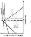
- Figure 6 shows a flue gas concentration before a three-way catalytic converter which enables most efficient conversion of NOx and CO in a catalytic zone of said a three-way converter. The following reactions take place in a three-way converter:
- air to fuel ratio ( ⁇ ) should be almost stoichiometric in flue gases before a three-way catalytic converter said ratio.
- the amount of O 2 to mean amount of CO (mole/mole) should be nearly stoichiometric; the mean amount of O 2 (in moles) to mean amount of CO gases (in moles) should be about 0.5/1 mole/mole in flue gases before said flue gases enter the three-way catalytical converter in the flow direction of flue gases.
- said exhaust gases may contain only 0.01-0.50 % or even only 0.01- 0.025 % of O 2 to enable catalytic conversions of CO and NOx to take place optimally in said three-way catalytic converter.
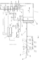
- Figs. 1-4 represent a burner automation according to the invention, and a burner suitable for applying the automation providing a capability of reaching, in such a burner, a sufficiently low amount of residual oxygen prior to a catalytic zone of a three-way converter
- a burner suitable for applying the automation providing a capability of reaching, in such a burner, a sufficiently low amount of residual oxygen prior to a catalytic zone of a three-way converter
- Figs. 1 and 2A are schematic views of burners wherein is implemented an adjustment of the invention for fuel and combustion air used for regulating the air/fuel ratio arriving in the flame.
- Fig. 3 shows in turn the fuel and combustion air flows of figs. 1 and 2A .
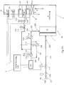
- Fig. 2B shows an alternative implementation for a secondary inlet flow of air.
- Each of figs. 1 and 2A shows a burner 100, which is intended for a gaseous or liquid fuel such as natural gas or fuel oil.
- the burner 100 comprises a combustion head 1 located in connection with a windbox 10, physically downstream of said cabinet, as well as a boiler 3 which is associated with the windbox 10 and opens into a flue gas conduit 4.
- the boiler 3 or the flue gas conduit 4 is provided with two catalytic zones 40, 40.
- the three-way converter 401 of the boiler 3 or the flue gas conduit 4 comprises two catalytic zones 40,40 in two separate three-way catalytic converters (401) for the afterburning of gases generated in thermal combustion conducted in the boiler 3. It is possible to deliver supplementary air into a space between two catalytic converters 401 having one catalytic zone each by way of an extra air supply conduit 222.
- the catalytic converter 401 is a three-way catalytic converter, which is selected in view of being suitable for the catalytic burning of combustion gases and for the reduction of NOx's generated in thermal combustion conducted with the combustion head 1 and the windbox 10 associated therewith and for the oxidation of hydrocarbon as well as carbon monoxide emissions in resulting flue gases.
- the burner 100 includes burner automation 5, 6, 7 whose operation is more closely illustrated in fig. 4 .
- the flue gas conduit 4 upstream of the catalytic zone 40 in the flowing direction of flue gas S, be supplied with combustion air I by way of an opening in a wall of the flue gas conduit 4. If desired, it is by way of the flue gas conduit that the exterior of the flame could also be supplied with fuel PA.
- the catalytic zone 40 comprises two three-way catalytic converters 401, which are successive in the traveling direction of flue gases and which enable oxides of nitrogen to be reduced, as well as unburned hydrocarbons (VOC) and carbon monoxide (CO) to be oxidized. It is possible that into a space between these is introduced supplementary air by way of an extra air supply conduit 222.
- fig 1 and 2A is presented also a mixer after the combustion chamber in the flue gas conduit before the catalytic zone of the first three-way catalytic converter, in the flow direction of flue gases.
- This mixer is intended for acquiring a homogenized flue gas mixture before delivering it to said catalytic converter.
- fig. 7 is presented one possible static mixer structure.
- the measuring instruments 6 include at least a plurality of lambda sensors 63; 63 1 , 63 2 , 63 3 , 63 4 , which measure the amount of residual oxygen in flue gases (the oxidation/reduction potential of flue gas) and which are located upstream and downstream of the two three-way catalytic converters 401, 401 with one catalytic zone 40 each.
- the measuring instruments 6 further include sensors 61; 61 1 , 61 2 , which are located downstream of both catalytic zones 40,40 in a traveling direction of the flue gases S and which measure the amount of nitrogen oxides NOx from flue gases, and/or sensors 62; 62 1 , 62 2 which measure the amount of carbon monoxide from flue gases. These sensors are located downstream of the catalytic zones 40,40 in the flowing direction of flue gases and, as a resuit, are used for measuring NOx and CO emissions in the flue gas conduit 4 after the catalytic converters 401.
- a supply conduit 210 for fuel PA opening onto the combustion head 1, that the combustion head 1 is supplied with a given fuel inlet flow Q PA or Q PAtot (cf. fig. 3 ), i.e. a given volume flow of fuel per unit time.
- a supply conduit 220 for combustion air I that supplies the windbox 10 with a given combustion air inlet flow Q l , or Q ltot , i.e. a given volume flow of combustion air per unit time.
- the combustion head 1 is supplied by way of a fuel supply conduit 210 with a total fuel inlet flow Q totPA .
- the total inlet flow Q totPA consists of two separately adjusted inlet flow portions Q PAA , Q PAB (cf. figs. 1 and 3 ), which proceed by way of separate fuel transfer pipe systems 215, 216 into the supply conduit 210.
- the first inlet flow portion Q PAA comprises a so-called primary inlet flow, which is adapted to travel in a first section 216 of the transfer pipe system that is in fluid communication with the supply conduit 210, and which makes up 70-100% of the inlet flow, preferably 80-100% of the total inlet flow Q totPA -
- the primary inlet flow Q PAA has its rate regulated with an actuator-equipped control valve, such as with a servo motor-operated control valve 7; 71.
- the second inlet flow portion comprises a secondary inlet flow Q PAB , which is adapted to travel in a second section 215 of the transfer pipe system that is likewise in fluid communication with the supply conduit 210, and which makes up 0-30% of the total inlet flow, preferably 0-20% of the total inlet flow Q totPA (cf. figs. 1 , 3 ).
- the rate adjustment for the secondary inlet flow Q PAB of fuel in the second section 215 of the transfer pipe system takes place by means of at least one actuator-equipped control valve 7; 71, and further preferably by means of at least one actuator-equipped on/off valve 7; 70 such as a magnet-operated on/off valve.
- the secondary inlet flow Q PAB has its rate regulated with two servo motor-operated control valves 7; 71 and with one on/off solenoid valve (check valve) 7; 70.
- the combustion air proceeds by way of a transfer pipe system 229 and a supply conduit 220 into the windbox 10. It is possible to regulate the amount of combustion air arriving in the windbox 10 with one or more blowers 7; 72, as well as with dampers 7; 73 having an adjustable opening degree.
- a frequency transformer To the blower 7; 72 in the transfer pipe system 229 is connected a frequency transformer by which the rotational speed of the blower can be adjusted, depending on the blower utilization degree, i.e. on the rate of a combustion air flow Q l , Q ltot to be delivered into the windbox. Visible in fig.
- supplementary air transfer pipe system 222 by which it is possible to introduce supplementary air between catalytic zones 40, 40 of the flue gas conduit 4 into a space between two catalytic converters 401 and 401
- the introduction of supplementary air in the transfer pipe system 222 is regulated with the actuator-equipped control valve 7; 71, as well as with the blower 7; 72 which is located in the air flowing direction downstream thereof and which can be fitted with an inverter.
- the burner shown in fig. 1 is adjusted as follows.
- the amount of a combustion air inlet flow Ql arriving in the windbox 10 is regulated with burner automation 5, 6, 7 (cf. fig. 4 ), and particularly with one or more blowers 7; 72 present in a combustion air transfer pipe system 229, as well as with dampers 7; 73 having an adjustable opening degree.
- the adjustment of the combustion air inlet flow Q l is based on a predetermined amount of residual oxygen O 2 in flue gases S, preferably on the amount of 1-2.5% residual oxygen in flue gases S.
- the amount of a primary inlet flow Q PAA of fuel is regulated by means of burner automation 5, 6, 7 and an actuator-equipped control valve, such as an electric motor-operated control valve 7; 71, present in a first transfer pipe system 116, likewise on the basis of a predetermined amount of residual oxygen in flue gases S, preferably on the amount of 1-2.5 % residual oxygen in flue gases.
- an actuator-equipped control valve such as an electric motor-operated control valve 7; 71, present in a first transfer pipe system 116, likewise on the basis of a predetermined amount of residual oxygen in flue gases S, preferably on the amount of 1-2.5 % residual oxygen in flue gases.
- the secondary inlet flow Q PAB of fuel is regulated by means of burner automation 5, 6, 7 and actuators 7 present in a second transfer pipe system 215, i.e. by way of two actuator-equipped control valves such as servo motor-operated control valves 7; 71 and one actuator-equipped on/off valve such as an on/off solenoid valve 7; 70 present in a section of the transfer pipe system 215.
- actuator-equipped control valves such as servo motor-operated control valves 7; 71 and one actuator-equipped on/off valve such as an on/off solenoid valve 7; 70 present in a section of the transfer pipe system 215.
- the adjustment of the secondary inlet flow Q PAB of fuel is based on the amount of residual oxygen measured with a lambda sensor 63 from flue gases, by way of which the burner automation 5, 6, 7 regulates the secondary inlet flow Q PAB , of fuel, which combines with a total inlet flow Q PAtot of fuel arriving by way of a supply conduit 210 at the combustion head 1, such that the ratio of the (total) inlet flow Q PAtot of fuel arriving at the combustion head 1 to the combustion air flow Q l arriving in the windbox is such that said amount of residual oxygen is 0.01-0.50 %, preferably 0.01-0.25%, in flue gases S prior to the catalytic zone 40 of said first three-way converter 401.
- the burner shown in fig. 2A differs from that presented in fig. 1 principally in the sense that this time the combustion air inlet flow Q ltot , arriving in the windbox 10 by way of a combustion air supply conduit 220, is adapted to consist of two separately adjusted portions of inlet flow Q lA , Q lB proceeding by way of a combustion air transfer pipe system 225, 226 into the supply conduit 220.
- the total combustion air flow Q totl arriving in the windbox 10, is now composed the same way as the total inlet flow Q totPA of fuel in fig. 1 , i.e. consists of two separate combustion air flows, just one of which, i.e. the secondary inlet flow of combustion air, is adjusted in a manner involving feedback.
- the first portion Q lA of a combustion air inlet flow comprises a primary inlet flow Q lA of combustion air, which is adapted to travel in a first section 226 of the transfer pipe system that is in fluid communication with the supply conduit 220, and which makes up 70-100%, preferably 80-100%, of the combustion air inlet flow O totl .
- the rate adjustment for the primary inlet flow Q lA of combustion air takes place by means of burner automation 5, 6, 7 (cf. fig. 4 ) and an actuator 7, such as an actuator-equipped control valve, for example a servo motor-operated control valve 7; 71, present in the first transfer pipe system.
- the second portion Q lB of a combustion air inlet flow comprises a secondary inlet flow, which is adapted to travel in a second section 226 of the transfer pipe system that is in fluid communication with the supply conduit 220, and which makes up 0-30%, preferably 0-20%, of the combustion air inlet flow Q l-tot .
- the rate adjustment for the secondary inlet flow Q lB of combustion air takes place by means of burner automation 5, 6, 7 and actuators 7 present in the second transfer pipe system 225.
- the rate adjustment for the secondary inlet flow Q lB of combustion air traveling in a line 215 takes place reversely to the adjustment of the secondary inlet flow Q PAB of fuel.
- the adjustment of the secondary inlet flow Q lB of combustion air is based on a procedure that, in order to attain a stoichiometric ratio between fuel and oxygen, the secondary inlet flow Q lB of air is restricted in normal condition with an appropriate actuator 7, such as an actuator-equipped control valve or a damper, constricting the secondary inlet flow Q lB of combustion air, and the secondary inlet flow Q lB is returned to an intake side of the blower 7; 72.
- the adjustment of a (primary) inlet flow Q lA of combustion air is similar to the adjustment of a fuel inlet flow Q PA shown in fig. 1 .
- the adjustment is based on estimating or determining by way of calculation how much the combustion air inlet flow Q lA to the combustion head 1 should be with a given burner utilization rate in order to attain the amount of 1-2.5% residual oxygen in flue gases prior to the catalytic zone 40 of the first three-way catalytic converter 40 in the direction of propagating flue gases.
- the adjustment of a secondary inlet flow Q lB of combustion air is based on the amount of residual oxygen, which has been measured or for flue gases S prior to the first catalytic zone 40, and by way of which the burner automation 5, 6, 7 regulates the secondary inlet flow Q lB , of combustion air which travels through the second transfer pipe system 225 and which changes the amount of a combustion air inlet flow Q ltot arriving in the windbox 10 by way of a supply conduit 220.
- the secondary combustion air inlet flow Q lB can be adjusted for example in such a way that the amount of combustion air, returned in normal condition by way of the second transfer pipe system 225 to an intake side of the blower 7; 72, will be constricted with an appropriate actuator 7 present in the transfer pipe system.
- an actuator 7 can be for example an extra damper 7; 73 shown in fig. 2A .
- the second transfer pipe system 225 may include for example a return branch 225' used for returning air by way of an appropriate actuator-equipped control valve 7; 71 to the intake side of a blower 7; 72 present in a main line 229, as shown in fig. 2B .
- the amount of air traveling by way of the transfer pipe system 225 is increased by increasing constriction of the secondary inlet flow Q lB .
- the adjustment of the secondary inlet flow Q lB of combustion air is based on the amount of residual oxygen measured with lambda sensors 63 from flue gases S upstream of the catalytic zone 40 of the first catalytic converter (in the traveling direction of flue gases).
- residual oxygen is measured after the first catalytic zone.
- the burner automation 5, 6, 7 regulates the secondary inlet flow Q lB of combustion air, which changes the amount of a total inlet flow Q totl of combustion air arriving in the windbox 10 by way of a supply conduit 220.
- the adjustment takes place in such a way that the ratio of the (total) inlet flow Q totl of combustion air (secondary inlet flow Q lB of combustion air + primary inlet flow Q lA of combustion air) to the total inlet flow Q PA of fuel arriving at a combustion head remains to be such that the measured amount of residual oxygen is 0.01-0.50% preferably 0.01-0.25% in flue gases S upstream of the first catalytic zone 40.
- the burners of both fig. 1 and fig. 2 are provided not only with lambda sensors 63 located upstream, downstream, upstream or at the three-way catalytic converters 401, 401 but also with CO sensors measuring the amount of carbon monoxides as well as with NOx sensors 61 measuring the amount of nitrogen oxides NOx in a flue gas conduit 4 downstream of both three-way catalytic converters 401 in the traveling direction of flue gases.
- the measurements conducted with these CO and NOx sensors 61, 62 provide a basis for further specifying the rates of the secondary inlet flows Q PAB and Q lB of fuel or combustion air in respective transfer pipe systems 215, 225.
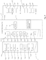
- the burner automation according to the invention is in turn elucidated by fig. 4 .
- the burner 100 is provided with integrated burner automation.
- the burner automation comprises a central processing unit 5, measuring instruments 6, and data transfer elements for providing appropriate control instructions 710 for operating actuators 7 which control the supplies of fuel PA and combustion air I for the burner 100.
- the central processing unit comprises a processor 52 and at least one memory element 51.
- the memory elements 51 contain various software products 510 for controlling the burner operation, especially for adjusting the total amounts Q l , Q ltot ,Q PA , Q totPA of air and fuel as well as for regulating the primary and secondary inlet flows Q PAA , Q PAB , Q lA , Q lB of fuel or air by means of respective actuators present in transfer and supply pipe systems.
- Fig. 4 displays software products 510 1 -510 9 , which are used for adjusting respectively the actuators visible in figs.1 , 2 and 4 by way of control instructions 710 1 -710 9 .
- the software products 510 1 -510 4 are associated with control instructions 710 1 -710 4 , which are used for controlling the supply of air I to the windbox 10 and a supplementary inlet flow in a pipe system 222 into the flue gas conduit 4 by way of actuators 7.
- control instructions 710 1 -710 4 which are used for controlling the supply of air I to the windbox 10 and a supplementary inlet flow in a pipe system 222 into the flue gas conduit 4 by way of actuators 7.
- the supply of combustion air to the windbox 10 is controlled by a blower 7; 72 as well as by a damper 7; 73 by way of control instructions 710 4 as well as 710 1 , and the air supply of the supplementary air inlet flow in the transfer pipe system 222 into the flue gas conduit 4 is controlled by an actuator-equipped control valve 7; 71 as well as an inverter-controlled blower 7; 72 by way of control instructions 710 2 and 710 3 .
- the software products 510 5 -510 8 are associated with control instructions 710 5 -710 8 to be established for adjusting the supply of fuel PA by way of respective actuators 7.
- the control instruction 710 8 is used for adjusting a control valve 7; 71 in a section 216 of the transfer pipe system for the primary inlet flow Q PAA of fuel ( fig. 1 ) or an actuator-equipped control valve 7; 71 in a transfer pipe system 219 for the total inlet flow Q PA ( fig. 2 ).
- the control instructions 710 5 , 710 6 , 710 7 are used for adjusting the secondary inlet flow Q PAB of fuel by way of actuators 7 present in a second section 215 of the transfer pipe system.
- Said actuators of the transfer pipe system's section 215 include two actuator-equipped control valves 7; 71 and one actuator-equipped on/off check valve 7; 70.
- the control instruction 710 9 is generated by software products 510 9 associated with the supply of combustion air. These software products and control instructions are related to the adjustment of a secondary inlet flow Q PlB of combustion air.
- the adjustment of secondary inlet flow is elucidated in figs. 2A and 2B in a second section 225 of the transfer pipe system for combustion air. The adjustment takes place by way of an actuator 7, such as a damper 7; 73 ( fig. 2A ), or by way of a return line 225' and an actuator-equipped control valve 7; 71 ( fig. 2B ), as described above.
- the measuring instruments 6 of burner automation are used for gathering information about the combustion process of a burner 100. Visible in an embodiment of the invention shown, in fig. 4 are lambda sensors 63; 63 1 , 63 2 , 63 3 , 634 measuring residual oxygen, CO sensors 62; 62 1 , 62 2 measuring the amount of carbon monoxides, as well as NOx sensors 61; 61 1 , 61 2 measuring the amount of nitrogen oxides NOx.
- the lambda sensors 63 are located upstream, downstream or at the three-way catalytic converters 401, 401 each with one catalytic zone in the traveling direction of flue gases S, the carbon monoxide sensors 62 as well as the nitrogen oxide sensors 61 being present downstream of the second catalytic zone 40 of the second catalytic converter.
- the data transfer elements are used for collecting measurement data from the measuring instruments 6 and for communicating the same to a processor 52 of the central processing unit 5 and to software products 510, comprising the reception of a data item regarding the amount of residual oxygen O 2 from the lambda sensors 63; 63 1 -63 4 which are present in flue gases and measure the oxidation/reduction potential of a flue gas and from the CO sensors 62; 62 1 , 62 2 which measure the amount of carbon monoxides, as well as from the NOx sensors 61; 61 1 , 61 2 which measure the amount of nitrogen oxides NOx.
- the transfer elements supply the processor 5; 52 as well as the burner control software 510 with the measurement data collected from the sensors 6.
- the burner control software 510 as well as the central processing unit 5 provide control instructions 710 for actuators 7 used for regulating the amount of air I and fuel PA.
- the central processing unit 52 is adapted by way of the burner control software 510 to generate control instructions as follows:
- the control instructions 710 1 , 710 4 are used for controlling by way of actuators 7 the amount of combustion air I arriving in the windbox 10, said actuators being preferably a blower 7; 72 as well as a damper 7; 73, the former regulating said amount of combustion air in a combustion air transfer pipe system 229 and being fitted with an inverter.
Landscapes
- Engineering & Computer Science (AREA)
- Chemical & Material Sciences (AREA)
- Mechanical Engineering (AREA)
- General Engineering & Computer Science (AREA)
- Combustion & Propulsion (AREA)
- Health & Medical Sciences (AREA)
- Chemical Kinetics & Catalysis (AREA)
- Environmental & Geological Engineering (AREA)
- Toxicology (AREA)
- Materials Engineering (AREA)
- Biomedical Technology (AREA)
- Oil, Petroleum & Natural Gas (AREA)
- General Chemical & Material Sciences (AREA)
- Analytical Chemistry (AREA)
Claims (17)
- Procédé de réduction d'oxyde(s) d'azote et de monoxyde de carbone à partir de gaz de carneau provenant d'un brûleur industriel (100), ledit procédé comprenant les étapes consistant à :a) obtenir un brûleur industriel (100) adapté pour brûler un combustible gazeux et/ou liquide, et comprenant une automatisation de brûleur contenant des instruments de mesure (6), et une zone de mélange accompagnée d'une chambre de combustion, ladite automatisation de brûleur étant en communication avec les instruments de mesure de la conduite de gaz de carneau, ladite chambre de combustion ou ladite conduite de gaz de carneau étant munie de deux convertisseurs catalytiques à trois voies (401, 401) successifs avec des zones catalytiques (40, 40), lesdites zones catalytiques (40, 40) sont successives dans une direction de progression des gaz de carneau, lesdits deux convertisseurs catalytiques à trois voies successifs comprenant un premier convertisseur catalytique à trois voies (401) comprenant une zone catalytique (40) et un second convertisseur catalytique à trois voies (401) comprenant une zone catalytique (40) ;b) livrer un débit d'entrée (Ql, Qltot) d'air de combustion et un débit d'entrée (QPA, QPAtot) de carburant dans la zone de mélange ;c) générer des gaz de carneau dans la chambre de combustion en réalisant la combustion d'air et d'un carburant délivré dans la zone de mélange lors de l'étape b) ;d) mesurer la quantité d'oxygène résiduel, dans les gaz de carneau en mesurant le potentiel d'oxydation/de réduction des gaz de carneau au moyen d'un capteur lambda ;e) diriger les gaz de carneau vers ledit au moins un convertisseur catalytique à trois voies (401) ;f) régler le débit d'entrée (Ql, Qltot) d'air de combustion et le débit d'entrée (QPA, QPAtot) de combustible arrivant dans la zone de mélange lors de l'étape b) au moyen de ladite automatisation de brûleur, de sorte que la quantité moyenne d'oxygène résiduel en mole comparée à la quantité moyenne de carbone monoxyde en mole, est de 0,5/1 (mole/mole) et O2 se situe dans la plage comprise entre 0,01 et 0,50 % en volume, de préférence dans la plage comprise entre 0,01 et 0,25 % en volume de gaz de carneau avant la première zone catalytique ou au niveau de ladite première zone catalytique desdits deux convertisseurs à trois voies ;g) délivrer de l'air supplémentaire entre les zones catalytiques (40, 40) desdits deux convertisseurs catalytiques à trois voies successifs, de sorte que la concentration dans les gaz de carneau après lesdites zones catalytiques (40, 40) se situe dans la plage comprise entre 0 et 9 ppm pour NOx et dans la plage comprise entre 0 et 100 ppm, de préférence dans la plage comprise entre 0 et 40 ppm pour CO.
- Procédé selon la revendication 1, dans lequel la livraison d'air supplémentaire est basée sur une mesure lambda après la zone catalytique (40) du premier convertisseur catalytique à trois voies (401).
- Procédé selon la revendication 1, dans lequel les convertisseurs catalytiques à trois voies réduisent les oxydes d'azote (NOX) en azote (N2) et en oxygène (O2) et oxydent les hydrocarbures (HC) et le monoxyde de carbone (CO) en dioxyde de carbone (CO2) et en eau (H2O).
- Procédé selon la revendication 1, dans lequel le gaz de carneau comprenant de l'O2, du CO, du NOx gazeux qui arrive dans la zone catalytique (40) dudit premier convertisseur catalytique (401) a été homogénéisé au moyen d'un mélangeur situé avant ladite première zone catalytique (40) dans la conduite de gaz de carneau ou dans la zone d'échange de chaleur.
- Procédé selon la revendication 1, dans lequel le gaz de carneau comprend avant les convertisseurs catalytiques à trois voies (401, 401) de l'O2 dans la plage comprise entre 0,01 et 0,50 %, de préférence dans la plage comprise entre 0,01 et 0,25 %, du CO à moins de 6000 ppm, des NOX à moins de 100 ppm et la proportion moyenne d'O2 au CO est de 0,5 mol/1 mol.
- Procédé selon la revendication 1, dans lequel la quantité de CO résiduel et de NOX est mesurée à partir des gaz de carneau et une concentration mesurée en NOX se situe dans la plage comprise entre 0 et 9 ppm, et une concentration mesurée en CO se situe dans la plage comprise entre 0 et 100 ppm, de préférence dans la plage comprise entre 0 et 40 ppm, et dans lequel le capteur de CO qui mesure la quantité de monoxydes de carbone, ainsi que le capteur de NOX qui mesure la quantité d'oxydes d'azote (NOX), sont situés en aval des deux zones catalytiques (40, 40) des convertisseurs catalytiques à trois voies (401, 401) dans la direction d'écoulement des gaz de carneau (S).
- Procédé selon la revendication 1, dans lequel la quantité d'oxygène résiduel dans les gaz de carneau arrivant audit premier convertisseur catalytique à trois voies est comprise entre 0,1 et 0,25 %, ledit oxygène étant défini par un capteur lambda, qui est situé en aval, au niveau de la première zone catalytique (40) desdits convertisseurs catalytiques.
- Procédé selon la revendication 7, dans lequel la quantité d'oxygène résiduel dans les gaz de carneau arrivant audit premier convertisseur catalytique à trois voies a été définie au moyen d'un capteur lambda situé entre les première et seconde zones catalytiques (40, 40) mais avant la livraison d'air supplémentaire entre les deux zones catalytiques (40, 40).
- Procédé selon la revendication 1, dans lequel le rapport du carburant (PA) délivré à la tête de combustion (1) par rapport à l'air de combustion (I) délivré dans la boîte à vent (10) est adapté pour être presque stœchiométrique, c'est-à-dire à l'intérieur de la plage lambda comprise entre 0,998 et 1,002.
- Procédé selon l'une quelconque des revendications précédentes, dans lequel le procédé comprend en outre le réglage de la quantité de carburant et d'air arrivant dans ladite zone de mélange en adaptant le rapport d'un débit d'air de combustion (Q|, Q|tot) arrivant dans une zone de mélange à un débit de carburant (QPA, QPAtot) arrivant en passant par une conduite de distribution de carburant (210) pour être tel que la quantité d'oxygène résiduel se trouve à l'intérieur de la plage comprise entre 0,01 et 0,25 %, dans des gaz de carneau à ladite première zone catalytique (40) dudit premier convertisseur catalytique à trois voies.
- Procédé selon la revendication 10, caractérisé en ce que le rapport du débit d'air de combustion (Q|, Q|tot) arrivant dans une zone de mélange, telle que la tête de combustion (1), au débit de carburant (QPA, QPAtot) arrivant dans une zone de mélange, telle que la tête de combustion (1), est adapté pour osciller à l'intérieur d'une certaine plage constamment stable, de préférence en adaptant la quantité de débit d'air de combustion (Q|, Q|tot) pour qu'elle reste constante et en amenant la quantité du débit de carburant (QPA, QPAtot) à osciller à l'intérieur d'une certaine plage de façon à approcher un ratio souhaité du débit d'air de combustion (Q|, Q|tot) arrivant dans la zone de mélange par rapport au débit de carburant (QPA, QPAtot) arrivant dans la zone de mélange, ledit rapport permettrait la présence de 0 à 0,50 % d'oxygène résiduel dans les gaz de carneau avant la première zone catalytique.
- Procédé selon la revendication 1, dans lequel- la quantité d'oxygène résiduel dans les gaz de carneau est mesurée en amont ou de préférence au niveau dudit premier convertisseur catalytique à trois voies,- la quantité d'un débit d'entrée d'air de combustion (Q|) arrivant à la zone de mélange est réglée au moyen d'une automatisation de brûleur (5, 6, 7) et d'un actionneur (7) présent dans un système de tuyauterie de transfert d'air de combustion, de sorte que le réglage du débit d'entrée d'air de combustion (Q|) est basé sur une quantité prédéterminée d'oxygène résiduel dans des gaz de carneau (S) avant la première zone catalytique desdits convertisseurs à trois voies, de préférence à la quantité comprise entre 1 et 2,5 % d'oxygène résiduel dans les gaz de carneau (S),- le débit d'entrée de carburant arrivant à la zone de mélange est adapté pour être constitué de deux parties réglées séparément (QPAA, QPAB) de flux d'entrée passant par voie d'un système de tuyauterie de transfert de carburant dans la conduite d'alimentation, dont la première partie (QPAA) de débit d'entrée comprend un débit d'entrée primaire, qui est adapté pour se déplacer dans une première section (216) du système de tuyauterie de transfert qui est en communication fluidique avec la conduite d'alimentation (210) et qui représente entre 70 et 100 % du débit d'entrée, de préférence entre 80 et 100 % du débit d'entrée (QPAtot) (total), et dont la seconde partie (QPAB) de débit d'entrée comprend un débit d'entrée secondaire, qui est adapté pour se déplacer dans une seconde section (215) du système de tuyauterie de transfert qui est également en communication fluidique avec la conduite d'alimentation (210) et qui représente entre 0 et 30 % du débit d'entrée, de préférence entre 0 et 20 % du débit d'entrée (QPAtot), moyennant quoi- le taux dudit débit d'entrée primaire (QPAA) est réglé au moyen d'une automatisation de brûleur (5, 6, 7) et d'un actionneur équipé d'un actionneur (7), telle qu'une vanne de commande actionnée par moteur électrique (7 ; 71), présents dans un premier système de tuyauterie de transfert, en fonction d'une quantité prédéterminée d'oxygène résiduel dans des gaz de carneau (S), de préférence à la quantité comprise entre 1 et 2,5 % d'oxygène résiduel dans les gaz de carneau, et sur le débit d'entrée primaire (QPAA) estimé ou calculé sur la base de celui-ci, qui se combine avec le flux d'entrée total (QPAtot) de carburant devant être délivré à la tête de combustion en passant par la conduite d'alimentation (210), et- le débit d'entrée secondaire (QPAB) de carburant est réglé au moyen d'une automatisation de brûleur (5, 6, 7) et d'actionneurs (7), telle qu'une vanne de commande équipée d'un actionneur (7 ; 70), présents dans un second système de tuyauterie de transfert, en fonction de la quantité d'oxygène résiduel présent dans les gaz de carneau vers la première zone catalytique desdits convertisseurs à trois voies et mesurée à partir d'un capteur de mesure du potentiel d'oxydation/de réduction de gaz de carneau (63), tel qu'un capteur lambda situé en amont, en aval, au niveau des convertisseurs catalytiques à trois voies (401, 401), au moyen desquels l'automatisation de brûleur (5, 6, 7) règle le débit d'entrée secondaire (QPAB) de carburant qui se combine avec le débit d'entrée total (QtotPA) de carburant arrivant au niveau de la tête de combustion (1) en passant par la conduite d'alimentation (210),- le rapport du débit d'entrée (QtotPA) (total) de carburant au débit d'air de combustion (Q|) arrivant dans la boîte à vent est maintenu de sorte que la quantité d'oxygène résiduel soit comprise entre 0,01 et 0,25 %, dans les gaz de carneau avant la première zone catalytique desdits convertisseurs à trois voies.
- Procédé selon la revendication 1, dans lequel les instruments de mesure (6) comprenant au moins un capteur (63), tel qu'un capteur lambda situé en amont, en aval ou au niveau des convertisseurs à trois voies (401, 401), lesdits capteurs lambda étant utilisés pour définir la quantité d'oxygène résiduel dans les gaz de carneau (potentiel d'oxydation/de réduction de gaz de carneau) avant la première zone catalytique desdits convertisseurs à trois voies, ledit procédé comprenant en outre les étapes suivantes consistant à :- régler un débit d'entrée (Q|) der de combustion (I) arrivant dans la zone de mélange, ledit réglage étant basé sur une quantité prédéfinie d'oxygène résiduel dans les gaz de carneau (S) avant la première zone catalytique desdits convertisseurs à trois voies, de préférence à la quantité comprise entre 1 et 2,5 % d'oxygène résiduel dans les gaz de carneau (S), et à la quantité d'air de combustion (I) estimée ou calculée sur la base de celui-ci et devant être délivré dans la zone de mélange, et- le débit d'entrée de carburant (QtotPA) est agencé pour arriver dans la zone de mélange en passant par la conduite d'alimentation en carburant (210) de sorte qu'il est constitué de deux parties régulées séparément (QPAA, QPAB) du débit d'entrée de carburant, dont la première partie (QPAA) du débit d'entrée comprend un débit d'entrée primaire qui représente entre 70 et 100 % du débit d'entrée, de préférence entre 80 et 100 % du débit d'entrée, et dont la seconde partie (QPAB) du débit d'entrée comprend un débit d'entrée secondaire qui représente entre 0 et 30 % du débit d'entrée, de préférence entre 0 et 20 % du débit d'entrée, moyennant quoi- le réglage dudit débit d'entrée primaire (QPAA) de carburant au moyen d'une automatisation de brûleur (5, 6, 7) est basé sur une quantité prédéfinie d'oxygène résiduel dans les gaz de carneau (S) avant la première zone catalytique desdits convertisseurs à trois voies, de préférence à la quantité comprise entre 1 et 2,5 % d'oxygène résiduel dans les gaz de carneau, et à la quantité du débit d'entrée primaire (QPAA) qui est estimée ou calculée sur la base de celui-ci dans le débit d'entrée (totPA) de carburant (PA) devant être délivré à la tête de combustion, et- le réglage dudit débit d'entrée secondaire (QPAB) de carburant au moyen d'une automatisation de brûleur (5, 6, 7) est basé sur la quantité d'oxygène résiduel mesuré à partir des gaz de carneau (S) avant la première zone catalytique desdits convertisseurs à trois voies, au moyen desquels l'automatisation de brûleur (5, 6, 7) règle la quantité du débit d'entrée secondaire (QPAB) dans le flux d'entrée (QtotPA) de carburant devant être délivré à la tête de combustion (1) de sorte que la quantité moyenne d'oxygène résiduel en mole par rapport à la quantité moyenne de monoxyde de carbone en mole est de 0,5/1 (mole/mole) et une quantité d'oxygène résiduel se situe à l'intérieur de la plage comprise entre 0,01 et 0,25 % de gaz de carneau avant la première zone catalytique (40) des convertisseurs catalytiques à trois voies.
- Procédé selon la revendication 13, dans lequel la mesure de la quantité d'oxygène résiduel des gaz de carneau (S) avant la première zone catalytique des convertisseurs catalytiques à trois voies est effectuée au moyen d'un capteur lambda situé après ladite première zone catalytique et l'automatisation de brûleur (5, 6, 7) règle la quantité du débit d'entrée secondaire (QPAB) dans le débit d'entrée (QtotPA) de carburant devant être livré à la tête de combustion (1) sur la base de ladite mesure d'oxygène résiduel.
- Procédé selon la revendication 14, dans lequel, par ailleurs, la quantité d'air de combustion supplémentaire alimentée entre les première et seconde zones catalytiques (40, 40) desdits deux convertisseurs à trois voies (401, 401) est basée sur la quantité d'oxygène mesurée, ladite mesure étant effectuée au moyen d'un capteur lambda situé après ladite seconde zone catalytique des convertisseurs catalytiques à trois voies.
- Automatisation de brûleur (5,6, 7) utilisée dans un procédé défini dans les revendications 1 et 12 comprenant- une unité de traitement central (5), comprenant un processeur (52) et au moins un élément de mémoire (51) qui/tous les deux inclut/incluent un produit logiciel/des produits logiciels (510) permettant de commander le fonctionnement d'un brûleur, en particulier permettant de régler la quantité (Q|, Q|tot, QPA, QPAtot) d'air et de carburant,- des instruments de mesure (6), tels que des capteurs (61, 62, 63), permettant de recueillir des informations concernant un processus de combustion devant être réglé,- des éléments de transfert de données permettant de recevoir des données de mesure provenant des instruments de mesure (6) et la communication de ceux-ci au processeur (52) et aux produits logiciels (510) de l'unité de traitement central (5), comprenant notamment la réception de données de mesure liées à la quantité d'oxygène résiduel, présent dans les gaz de carneau avant la première zone catalytique des deux convertisseurs catalytiques successifs comportant chacun au moins une zone catalytique, à partir d'un capteur de mesure du potentiel d'oxydation/de réduction de gaz de carneau (63), tel qu'un capteur lambda situé en amont, en aval ou au niveau des convertisseurs à trois voies (401, 401), et la communication des données de mesure au processeur (5 ; 52) et au logiciel de commande de brûleur (510) de l'unité de traitement central, ainsi que pour la transmission d'instructions de commande, générées au moyen de l'unité de traitement central, à des actionneurs (7) réglant la quantité d'air et de carburant (PA) devant être délivrée, dans laquelle- l'unité de traitement central (52) est adaptée pour générer, par le biais du logiciel de commande de brûleur (510),- des instructions de commande (7105, 7106, 7107) liées à la quantité du débit d'entrée secondaire (QPAB) de carburant, moyennant quoi le débit d'entrée secondaire (QPAB) de carburant peut être réglé d'une manière telle que la quantité (QPAB) du débit d'entrée secondaire dans le débit d'entrée (QPAtot) du carburant est telle que la quantité d'oxygène résiduel se situe à l'intérieur de la plage comprise entre 0,01 et 0,50 %, de préférence à l'intérieur de la plage comprise entre 0,01 et 0,25 % de gaz de carneau (S) avant la première zone catalytique (40) des deux convertisseurs catalytiques à trois voies successifs (401, 401) comportant chacun au moins une zone catalytique (40),- des instructions de commande (7108) liées à la quantité du débit d'entrée primaire (QPAA) de carburant, qui sont basées sur une quantité prédéterminée d'oxygène résiduel dans les gaz de carneau (S), de préférence à la quantité comprise entre 1 et 2,5 % d'oxygène résiduel dans les gaz de carneau (40),- des instructions de commande (7101, 7104) destinées au débit d'entrée d'air de combustion (I), qui sont utilisées pour le réglage de la quantité du débit d'entrée (Q|) d'air de combustion arrivant dans la boîte à vent (10) en passant par la conduite de distribution d'air de combustion (220), en fonction d'une quantité prédéterminée d'oxygène d'air de combustion résiduel dans des gaz de carneau, de préférence à la quantité comprise entre 1 et 2,5 % d'oxygène résiduel dans les gaz de carneau, et après avoir été générés par unité de traitement central (5), les éléments de transfert de données sont adaptés pour communiquer des instructions de commande (7105, 7106, 7107) pour le débit d'entrée secondaire (QPAB) de carburant (PA) vers un actionneur (7) réglant la quantité du flux d'entrée secondaire, de préférence à une vanne de commande équipée d'un actionneur (7 ; 71), telle qu'une vanne de commande actionnée par un servomoteur, réglant ladite quantité du débit d'entrée secondaire (QPAB) dans le système de tuyauterie (215) pour le débit d'entrée secondaire,- des instructions de commande (7108) pour le débit d'entrée primaire (QPAA) de carburant (PA) vers un actionneur (7) réglant la quantité du débit d'entrée primaire, de préférence à une vanne de commande équipée d'un actionneur (7 ; 71), telle qu'une vanne de commande actionnée par servomoteur, réglant ladite quantité du débit d'entrée primaire dans le système de tuyauterie pour le débit d'entrée primaire, et- des instructions de commande (7101, 7104) destinées au débit d'entrée d'air de combustion (I) vers un actionneur (7) réglant la quantité d'air de combustion, de préférence vers l'onduleur d'une souffleuse (7 ; 72) réglant ladite quantité d'air de combustion dans le système de tuyauterie de transfert d'air de combustion, et/ou des moteurs électriques, tels que des vannes actionnées par servomoteur, réglant les paramètres des amortisseurs et des vannes.
- Automatisation de brûleur selon la revendication 16, dans laquelle ladite automatisation de brûleur utilise un prédicteur de type Smith pour régler la quantité du débit d'entrée secondaire.
Priority Applications (1)
| Application Number | Priority Date | Filing Date | Title |
|---|---|---|---|
| PL16165426T PL3098511T3 (pl) | 2015-04-14 | 2016-04-14 | Sposób redukcji tlenku(-ów) azotu i tlenku węgla z gazów spalinowych i odpowiednia automatyka palnika |
Applications Claiming Priority (1)
| Application Number | Priority Date | Filing Date | Title |
|---|---|---|---|
| FI20155279 | 2015-04-14 |
Publications (2)
| Publication Number | Publication Date |
|---|---|
| EP3098511A1 EP3098511A1 (fr) | 2016-11-30 |
| EP3098511B1 true EP3098511B1 (fr) | 2020-02-05 |
Family
ID=55754214
Family Applications (1)
| Application Number | Title | Priority Date | Filing Date |
|---|---|---|---|
| EP16165426.4A Active EP3098511B1 (fr) | 2015-04-14 | 2016-04-14 | Procédé de réduction des oxydes d'azote et du monoxyde de carbone à partir de gaz de carneau et réglage de combustion correspondante |
Country Status (4)
| Country | Link |
|---|---|
| US (2) | US10295182B2 (fr) |
| EP (1) | EP3098511B1 (fr) |
| CN (2) | CN106090911A (fr) |
| PL (1) | PL3098511T3 (fr) |
Families Citing this family (10)
| Publication number | Priority date | Publication date | Assignee | Title |
|---|---|---|---|---|
| EP2789915A1 (fr) * | 2013-04-10 | 2014-10-15 | Alstom Technology Ltd | Procédé de fonctionnement d'une chambre de combustion et chambre de combustion |
| US10697651B2 (en) * | 2015-12-23 | 2020-06-30 | Intel Corporation | Energy efficient combustion heater control |
| EP3963269A4 (fr) * | 2019-04-29 | 2023-07-05 | Carbonquest, Inc. | Systèmes et procédés de traitement et/ou de séquestration d'émission de bâtiment |
| EP4050258B1 (fr) * | 2021-02-26 | 2024-06-05 | Siemens Aktiengesellschaft | Procédé de régulation d'un dispositif de brûleur avec détermination de la puissance à l'aide d'un paramètre de combustible |
| JP7574137B2 (ja) * | 2021-05-17 | 2024-10-28 | 東京瓦斯株式会社 | 燃焼システム |
| CN113503538B (zh) * | 2021-07-25 | 2024-09-13 | 扬州超威燃烧器有限公司 | 一种炭黑尾气低氮燃烧器及其使用方法 |
| CN113758018B (zh) * | 2021-09-06 | 2022-10-28 | 广东超人节能厨卫电器有限公司 | 一种风机装置及热水器 |
| US12367498B2 (en) | 2021-10-11 | 2025-07-22 | Carbonquest, Inc. | Carbon management systems and method for management of carbon use and/or production in buildings |
| CN114110559B (zh) * | 2021-11-12 | 2023-05-23 | 东方电气集团东方锅炉股份有限公司 | 二次再热锅炉的烟气挡板布置结构和再热汽温控制方法 |
| TWI847628B (zh) * | 2023-03-24 | 2024-07-01 | 泰鋒染化工業股份有限公司 | 降低二氧化碳排放的鍋爐燃燒方法 |
Family Cites Families (17)
| Publication number | Priority date | Publication date | Assignee | Title |
|---|---|---|---|---|
| US3757521A (en) * | 1971-04-05 | 1973-09-11 | Chemical Construction Corp | Integrated engine exhaust emission control system |
| DE3019622A1 (de) | 1980-05-22 | 1981-11-26 | SIEMENS AG AAAAA, 1000 Berlin und 8000 München | Verfahren zum betrieb einer vergasungsbrenner/heizkesselanlage |
| GB2092911A (en) * | 1981-02-13 | 1982-08-25 | Engelhard Corp | Method for catalytic purification of combustion exhaust gases |
| DE19741199C2 (de) * | 1997-09-18 | 2000-10-26 | Siemens Ag | Statischer Mischer |
| US6634168B1 (en) | 1998-10-19 | 2003-10-21 | Nissan Motor Co., Ltd. | Exhaust gas purification system |
| JP4312325B2 (ja) * | 1999-12-28 | 2009-08-12 | 本田技研工業株式会社 | 排ガス浄化用触媒装置の劣化状態評価方法 |
| FI20012201A0 (fi) * | 2001-11-13 | 2001-11-13 | Oilon Internat Oy | Laite polttolaitteelle syötettävän polttoainemäärän ja hajotusainemäärän ohjaamiseksi |
| US6945033B2 (en) * | 2003-06-26 | 2005-09-20 | Ford Global Technologies, Llc | Catalyst preconditioning method and system |
| US7399458B1 (en) | 2005-11-18 | 2008-07-15 | Callidus Technologies Inc. | Fired equipment with catalytic converter and method of operating same |
| KR101373590B1 (ko) | 2006-07-04 | 2014-03-12 | 미우라고교 가부시키카이샤 | 보일러 |
| AT504523B1 (de) * | 2007-01-04 | 2008-06-15 | Glueck Christoph Ing | Verfahren zum verfeuern von flüssigen brennstoffen |
| JP2008253976A (ja) | 2007-03-15 | 2008-10-23 | Miura Co Ltd | 触媒劣化防止装置および低NOx燃焼装置 |
| JP5369899B2 (ja) * | 2009-05-27 | 2013-12-18 | 株式会社Ihi | バーナ |
| US8578704B2 (en) * | 2010-04-28 | 2013-11-12 | Tecogen, Inc. | Assembly and method for reducing nitrogen oxides, carbon monoxide and hydrocarbons in exhausts of internal combustion engines |
| JP5485193B2 (ja) | 2011-01-26 | 2014-05-07 | 大陽日酸株式会社 | バーナの燃焼方法 |
| WO2014154931A1 (fr) | 2013-03-27 | 2014-10-02 | Oilon Oy | Procédé et appareil pour brûler des hydrocarbures et d'autres liquides et gaz |
| WO2015038994A1 (fr) * | 2013-09-13 | 2015-03-19 | Clearstak Llc | Dispositif de commande d'alimentation en carburant et d'alimentation en air pour four à biocarburant |
-
2016
- 2016-04-14 CN CN201610268607.7A patent/CN106090911A/zh active Pending
- 2016-04-14 US US15/099,148 patent/US10295182B2/en not_active Expired - Fee Related
- 2016-04-14 US US15/099,091 patent/US20160305655A1/en not_active Abandoned
- 2016-04-14 PL PL16165426T patent/PL3098511T3/pl unknown
- 2016-04-14 EP EP16165426.4A patent/EP3098511B1/fr active Active
- 2016-04-14 CN CN201610268606.2A patent/CN106439904A/zh active Pending
Non-Patent Citations (1)
| Title |
|---|
| None * |
Also Published As
| Publication number | Publication date |
|---|---|
| US20160305659A1 (en) | 2016-10-20 |
| EP3098511A1 (fr) | 2016-11-30 |
| CN106439904A (zh) | 2017-02-22 |
| PL3098511T3 (pl) | 2020-08-10 |
| US10295182B2 (en) | 2019-05-21 |
| US20160305655A1 (en) | 2016-10-20 |
| CN106090911A (zh) | 2016-11-09 |
Similar Documents
| Publication | Publication Date | Title |
|---|---|---|
| EP3098511B1 (fr) | Procédé de réduction des oxydes d'azote et du monoxyde de carbone à partir de gaz de carneau et réglage de combustion correspondante | |
| CN104780996B (zh) | 废气净化装置和减少来自于化石燃料发电站发电站的废气中氮氧化物的方法 | |
| CN105545434B (zh) | 用于燃气涡轮机系统中的排放物控制的系统和方法 | |
| CN105781765A (zh) | 用于催化转化器系统的基于模型控制的系统和方法 | |
| CN105986867A (zh) | 用于监测中间床氧化剂注入系统的健康状况的系统和方法 | |
| CN102828802B (zh) | 用于燃烧器排放物控制的系统和方法 | |
| EP2581583A1 (fr) | Procédé d'exploitation d'une turbine à gaz | |
| CN105697166A (zh) | 用于根据催化转化器性能控制空气燃料比的系统和方法 | |
| CN112867849B (zh) | 用于废气后处理的方法和废气后处理系统 | |
| CN204213910U (zh) | 用于燃烧烃或其它可燃液体和气体的装置 | |
| TWI252125B (en) | Emission treatment system | |
| CN105697164A (zh) | 用于排气后处理系统中的排放的控制的方法和系统 | |
| US20140250857A1 (en) | Low-concentration methane gas oxidation system using exhaust heat from gas turbine engine | |
| US8763368B1 (en) | Systems and methods for controlling a combustion engine | |
| CN103857891B (zh) | 贫燃料吸入燃气轮机 | |
| WO2013147944A2 (fr) | Aube directrice de compresseur et commande de pilote pour moteur à turbine à gaz | |
| CN101680341A (zh) | 带机载制氨的多发动机系统 | |
| CN116601380A (zh) | 用于运行废气后处理设备的方法 | |
| AU2001248946B2 (en) | A method of controlling the concentration of nitrogen oxides, hydrocarbons and carbon monoxide in conjunction with the cleansing of emission gases | |
| JP2007285564A (ja) | 連続鋼材加熱炉およびこれを用いた鋼材の加熱方法 | |
| KR101704270B1 (ko) | 배출가스의 정화성능 향상을 위한 제어방법 | |
| JP7664721B2 (ja) | 脱硝装置の制御装置、ボイラ設備、脱硝装置の制御方法及び脱硝装置の制御プログラム | |
| AU2001248946A1 (en) | A method of controlling the concentration of nitrogen oxides, hydrocarbons and carbon monoxide in conjunction with the cleansing of emission gases | |
| US20150121891A1 (en) | Oxidation system for treatment of low-concentration methane gas provided with multiple oxidizers | |
| JP2007125485A (ja) | 窒素酸化物および一酸化炭素の低減方法およびその装置 |
Legal Events
| Date | Code | Title | Description |
|---|---|---|---|
| PUAI | Public reference made under article 153(3) epc to a published international application that has entered the european phase |
Free format text: ORIGINAL CODE: 0009012 |
|
| AK | Designated contracting states |
Kind code of ref document: A1 Designated state(s): AL AT BE BG CH CY CZ DE DK EE ES FI FR GB GR HR HU IE IS IT LI LT LU LV MC MK MT NL NO PL PT RO RS SE SI SK SM TR |
|
| AX | Request for extension of the european patent |
Extension state: BA ME |
|
| STAA | Information on the status of an ep patent application or granted ep patent |
Free format text: STATUS: REQUEST FOR EXAMINATION WAS MADE |
|
| 17P | Request for examination filed |
Effective date: 20170529 |
|
| RBV | Designated contracting states (corrected) |
Designated state(s): AL AT BE BG CH CY CZ DE DK EE ES FI FR GB GR HR HU IE IS IT LI LT LU LV MC MK MT NL NO PL PT RO RS SE SI SK SM TR |
|
| STAA | Information on the status of an ep patent application or granted ep patent |
Free format text: STATUS: EXAMINATION IS IN PROGRESS |
|
| 17Q | First examination report despatched |
Effective date: 20171130 |
|
| GRAP | Despatch of communication of intention to grant a patent |
Free format text: ORIGINAL CODE: EPIDOSNIGR1 |
|
| STAA | Information on the status of an ep patent application or granted ep patent |
Free format text: STATUS: GRANT OF PATENT IS INTENDED |
|
| INTG | Intention to grant announced |
Effective date: 20190405 |
|
| GRAJ | Information related to disapproval of communication of intention to grant by the applicant or resumption of examination proceedings by the epo deleted |
Free format text: ORIGINAL CODE: EPIDOSDIGR1 |
|
| STAA | Information on the status of an ep patent application or granted ep patent |
Free format text: STATUS: EXAMINATION IS IN PROGRESS |
|
| INTC | Intention to grant announced (deleted) | ||
| GRAS | Grant fee paid |
Free format text: ORIGINAL CODE: EPIDOSNIGR3 |
|
| STAA | Information on the status of an ep patent application or granted ep patent |
Free format text: STATUS: GRANT OF PATENT IS INTENDED |
|
| GRAP | Despatch of communication of intention to grant a patent |
Free format text: ORIGINAL CODE: EPIDOSNIGR1 |
|
| INTG | Intention to grant announced |
Effective date: 20190923 |
|
| RAP1 | Party data changed (applicant data changed or rights of an application transferred) |
Owner name: OILON TECHNOLOGY OY |
|
| GRAA | (expected) grant |
Free format text: ORIGINAL CODE: 0009210 |
|
| STAA | Information on the status of an ep patent application or granted ep patent |
Free format text: STATUS: THE PATENT HAS BEEN GRANTED |
|
| AK | Designated contracting states |
Kind code of ref document: B1 Designated state(s): AL AT BE BG CH CY CZ DE DK EE ES FI FR GB GR HR HU IE IS IT LI LT LU LV MC MK MT NL NO PL PT RO RS SE SI SK SM TR |
|
| REG | Reference to a national code |
Ref country code: GB Ref legal event code: FG4D |
|
| REG | Reference to a national code |
Ref country code: AT Ref legal event code: REF Ref document number: 1230181 Country of ref document: AT Kind code of ref document: T Effective date: 20200215 |
|
| REG | Reference to a national code |
Ref country code: DE Ref legal event code: R096 Ref document number: 602016029020 Country of ref document: DE |
|
| REG | Reference to a national code |
Ref country code: IE Ref legal event code: FG4D |
|
| REG | Reference to a national code |
Ref country code: CH Ref legal event code: EP |
|
| REG | Reference to a national code |
Ref country code: FI Ref legal event code: FGE |
|
| REG | Reference to a national code |
Ref country code: NL Ref legal event code: FP |
|
| PG25 | Lapsed in a contracting state [announced via postgrant information from national office to epo] |
Ref country code: RS Free format text: LAPSE BECAUSE OF FAILURE TO SUBMIT A TRANSLATION OF THE DESCRIPTION OR TO PAY THE FEE WITHIN THE PRESCRIBED TIME-LIMIT Effective date: 20200205 Ref country code: NO Free format text: LAPSE BECAUSE OF FAILURE TO SUBMIT A TRANSLATION OF THE DESCRIPTION OR TO PAY THE FEE WITHIN THE PRESCRIBED TIME-LIMIT Effective date: 20200505 Ref country code: PT Free format text: LAPSE BECAUSE OF FAILURE TO SUBMIT A TRANSLATION OF THE DESCRIPTION OR TO PAY THE FEE WITHIN THE PRESCRIBED TIME-LIMIT Effective date: 20200628 |
|
| REG | Reference to a national code |
Ref country code: LT Ref legal event code: MG4D |
|
| PG25 | Lapsed in a contracting state [announced via postgrant information from national office to epo] |
Ref country code: IS Free format text: LAPSE BECAUSE OF FAILURE TO SUBMIT A TRANSLATION OF THE DESCRIPTION OR TO PAY THE FEE WITHIN THE PRESCRIBED TIME-LIMIT Effective date: 20200605 Ref country code: BG Free format text: LAPSE BECAUSE OF FAILURE TO SUBMIT A TRANSLATION OF THE DESCRIPTION OR TO PAY THE FEE WITHIN THE PRESCRIBED TIME-LIMIT Effective date: 20200505 Ref country code: HR Free format text: LAPSE BECAUSE OF FAILURE TO SUBMIT A TRANSLATION OF THE DESCRIPTION OR TO PAY THE FEE WITHIN THE PRESCRIBED TIME-LIMIT Effective date: 20200205 Ref country code: GR Free format text: LAPSE BECAUSE OF FAILURE TO SUBMIT A TRANSLATION OF THE DESCRIPTION OR TO PAY THE FEE WITHIN THE PRESCRIBED TIME-LIMIT Effective date: 20200506 Ref country code: SE Free format text: LAPSE BECAUSE OF FAILURE TO SUBMIT A TRANSLATION OF THE DESCRIPTION OR TO PAY THE FEE WITHIN THE PRESCRIBED TIME-LIMIT Effective date: 20200205 Ref country code: LV Free format text: LAPSE BECAUSE OF FAILURE TO SUBMIT A TRANSLATION OF THE DESCRIPTION OR TO PAY THE FEE WITHIN THE PRESCRIBED TIME-LIMIT Effective date: 20200205 |
|
| PG25 | Lapsed in a contracting state [announced via postgrant information from national office to epo] |
Ref country code: LT Free format text: LAPSE BECAUSE OF FAILURE TO SUBMIT A TRANSLATION OF THE DESCRIPTION OR TO PAY THE FEE WITHIN THE PRESCRIBED TIME-LIMIT Effective date: 20200205 Ref country code: EE Free format text: LAPSE BECAUSE OF FAILURE TO SUBMIT A TRANSLATION OF THE DESCRIPTION OR TO PAY THE FEE WITHIN THE PRESCRIBED TIME-LIMIT Effective date: 20200205 Ref country code: SM Free format text: LAPSE BECAUSE OF FAILURE TO SUBMIT A TRANSLATION OF THE DESCRIPTION OR TO PAY THE FEE WITHIN THE PRESCRIBED TIME-LIMIT Effective date: 20200205 Ref country code: DK Free format text: LAPSE BECAUSE OF FAILURE TO SUBMIT A TRANSLATION OF THE DESCRIPTION OR TO PAY THE FEE WITHIN THE PRESCRIBED TIME-LIMIT Effective date: 20200205 Ref country code: SK Free format text: LAPSE BECAUSE OF FAILURE TO SUBMIT A TRANSLATION OF THE DESCRIPTION OR TO PAY THE FEE WITHIN THE PRESCRIBED TIME-LIMIT Effective date: 20200205 Ref country code: CZ Free format text: LAPSE BECAUSE OF FAILURE TO SUBMIT A TRANSLATION OF THE DESCRIPTION OR TO PAY THE FEE WITHIN THE PRESCRIBED TIME-LIMIT Effective date: 20200205 Ref country code: ES Free format text: LAPSE BECAUSE OF FAILURE TO SUBMIT A TRANSLATION OF THE DESCRIPTION OR TO PAY THE FEE WITHIN THE PRESCRIBED TIME-LIMIT Effective date: 20200205 Ref country code: RO Free format text: LAPSE BECAUSE OF FAILURE TO SUBMIT A TRANSLATION OF THE DESCRIPTION OR TO PAY THE FEE WITHIN THE PRESCRIBED TIME-LIMIT Effective date: 20200205 |
|
| REG | Reference to a national code |
Ref country code: DE Ref legal event code: R097 Ref document number: 602016029020 Country of ref document: DE |
|
| REG | Reference to a national code |
Ref country code: AT Ref legal event code: MK05 Ref document number: 1230181 Country of ref document: AT Kind code of ref document: T Effective date: 20200205 |
|
| PG25 | Lapsed in a contracting state [announced via postgrant information from national office to epo] |
Ref country code: MC Free format text: LAPSE BECAUSE OF FAILURE TO SUBMIT A TRANSLATION OF THE DESCRIPTION OR TO PAY THE FEE WITHIN THE PRESCRIBED TIME-LIMIT Effective date: 20200205 |
|
| REG | Reference to a national code |
Ref country code: CH Ref legal event code: PL |
|
| PLBE | No opposition filed within time limit |
Free format text: ORIGINAL CODE: 0009261 |
|
| STAA | Information on the status of an ep patent application or granted ep patent |
Free format text: STATUS: NO OPPOSITION FILED WITHIN TIME LIMIT |
|
| 26N | No opposition filed |
Effective date: 20201106 |
|
| PG25 | Lapsed in a contracting state [announced via postgrant information from national office to epo] |
Ref country code: LI Free format text: LAPSE BECAUSE OF NON-PAYMENT OF DUE FEES Effective date: 20200430 Ref country code: CH Free format text: LAPSE BECAUSE OF NON-PAYMENT OF DUE FEES Effective date: 20200430 Ref country code: LU Free format text: LAPSE BECAUSE OF NON-PAYMENT OF DUE FEES Effective date: 20200414 Ref country code: AT Free format text: LAPSE BECAUSE OF FAILURE TO SUBMIT A TRANSLATION OF THE DESCRIPTION OR TO PAY THE FEE WITHIN THE PRESCRIBED TIME-LIMIT Effective date: 20200205 |
|
| REG | Reference to a national code |
Ref country code: BE Ref legal event code: MM Effective date: 20200430 |
|
| PG25 | Lapsed in a contracting state [announced via postgrant information from national office to epo] |
Ref country code: BE Free format text: LAPSE BECAUSE OF NON-PAYMENT OF DUE FEES Effective date: 20200430 Ref country code: SI Free format text: LAPSE BECAUSE OF FAILURE TO SUBMIT A TRANSLATION OF THE DESCRIPTION OR TO PAY THE FEE WITHIN THE PRESCRIBED TIME-LIMIT Effective date: 20200205 |
|
| GBPC | Gb: european patent ceased through non-payment of renewal fee |
Effective date: 20200505 |
|
| PG25 | Lapsed in a contracting state [announced via postgrant information from national office to epo] |
Ref country code: IE Free format text: LAPSE BECAUSE OF NON-PAYMENT OF DUE FEES Effective date: 20200414 Ref country code: GB Free format text: LAPSE BECAUSE OF NON-PAYMENT OF DUE FEES Effective date: 20200505 |
|
| PG25 | Lapsed in a contracting state [announced via postgrant information from national office to epo] |
Ref country code: MT Free format text: LAPSE BECAUSE OF FAILURE TO SUBMIT A TRANSLATION OF THE DESCRIPTION OR TO PAY THE FEE WITHIN THE PRESCRIBED TIME-LIMIT Effective date: 20200205 Ref country code: CY Free format text: LAPSE BECAUSE OF FAILURE TO SUBMIT A TRANSLATION OF THE DESCRIPTION OR TO PAY THE FEE WITHIN THE PRESCRIBED TIME-LIMIT Effective date: 20200205 |
|
| PGFP | Annual fee paid to national office [announced via postgrant information from national office to epo] |
Ref country code: TR Payment date: 20220331 Year of fee payment: 7 Ref country code: PL Payment date: 20220315 Year of fee payment: 7 |
|
| PG25 | Lapsed in a contracting state [announced via postgrant information from national office to epo] |
Ref country code: MK Free format text: LAPSE BECAUSE OF FAILURE TO SUBMIT A TRANSLATION OF THE DESCRIPTION OR TO PAY THE FEE WITHIN THE PRESCRIBED TIME-LIMIT Effective date: 20200205 Ref country code: AL Free format text: LAPSE BECAUSE OF FAILURE TO SUBMIT A TRANSLATION OF THE DESCRIPTION OR TO PAY THE FEE WITHIN THE PRESCRIBED TIME-LIMIT Effective date: 20200205 |
|
| PGFP | Annual fee paid to national office [announced via postgrant information from national office to epo] |
Ref country code: NL Payment date: 20220421 Year of fee payment: 7 |
|
| PGFP | Annual fee paid to national office [announced via postgrant information from national office to epo] |
Ref country code: IT Payment date: 20220415 Year of fee payment: 7 Ref country code: FR Payment date: 20220414 Year of fee payment: 7 Ref country code: DE Payment date: 20220422 Year of fee payment: 7 |
|
| PGFP | Annual fee paid to national office [announced via postgrant information from national office to epo] |
Ref country code: FI Payment date: 20220419 Year of fee payment: 7 |
|
| REG | Reference to a national code |
Ref country code: DE Ref legal event code: R119 Ref document number: 602016029020 Country of ref document: DE |
|
| REG | Reference to a national code |
Ref country code: NL Ref legal event code: MM Effective date: 20230501 |
|
| PG25 | Lapsed in a contracting state [announced via postgrant information from national office to epo] |
Ref country code: NL Free format text: LAPSE BECAUSE OF NON-PAYMENT OF DUE FEES Effective date: 20230501 Ref country code: FR Free format text: LAPSE BECAUSE OF NON-PAYMENT OF DUE FEES Effective date: 20230430 Ref country code: FI Free format text: LAPSE BECAUSE OF NON-PAYMENT OF DUE FEES Effective date: 20230414 Ref country code: DE Free format text: LAPSE BECAUSE OF NON-PAYMENT OF DUE FEES Effective date: 20231103 |
|
| PG25 | Lapsed in a contracting state [announced via postgrant information from national office to epo] |
Ref country code: IT Free format text: LAPSE BECAUSE OF NON-PAYMENT OF DUE FEES Effective date: 20230414 |
|
| PG25 | Lapsed in a contracting state [announced via postgrant information from national office to epo] |
Ref country code: PL Free format text: LAPSE BECAUSE OF NON-PAYMENT OF DUE FEES Effective date: 20230414 |
|
| PG25 | Lapsed in a contracting state [announced via postgrant information from national office to epo] |
Ref country code: PL Free format text: LAPSE BECAUSE OF NON-PAYMENT OF DUE FEES Effective date: 20230414 |