EP3098543A1 - Dampfkompressionssystem mit einem auswerfer und einem rückschlagventil - Google Patents
Dampfkompressionssystem mit einem auswerfer und einem rückschlagventil Download PDFInfo
- Publication number
- EP3098543A1 EP3098543A1 EP15169553.3A EP15169553A EP3098543A1 EP 3098543 A1 EP3098543 A1 EP 3098543A1 EP 15169553 A EP15169553 A EP 15169553A EP 3098543 A1 EP3098543 A1 EP 3098543A1
- Authority
- EP
- European Patent Office
- Prior art keywords
- inlet
- refrigerant
- evaporator
- outlet
- compressor unit
- Prior art date
- Legal status (The legal status is an assumption and is not a legal conclusion. Google has not performed a legal analysis and makes no representation as to the accuracy of the status listed.)
- Withdrawn
Links
- 230000006835 compression Effects 0.000 title claims abstract description 39
- 238000007906 compression Methods 0.000 title claims abstract description 39
- 239000003507 refrigerant Substances 0.000 claims abstract description 151
- 239000012530 fluid Substances 0.000 claims description 6
- 239000007788 liquid Substances 0.000 description 17
- 239000007789 gas Substances 0.000 description 3
- 230000007423 decrease Effects 0.000 description 2
- 230000003247 decreasing effect Effects 0.000 description 2
- 239000007792 gaseous phase Substances 0.000 description 2
- 238000010438 heat treatment Methods 0.000 description 2
- 238000005057 refrigeration Methods 0.000 description 2
- 238000001816 cooling Methods 0.000 description 1
- 230000000694 effects Effects 0.000 description 1
Images
Classifications
-
- F—MECHANICAL ENGINEERING; LIGHTING; HEATING; WEAPONS; BLASTING
- F25—REFRIGERATION OR COOLING; COMBINED HEATING AND REFRIGERATION SYSTEMS; HEAT PUMP SYSTEMS; MANUFACTURE OR STORAGE OF ICE; LIQUEFACTION SOLIDIFICATION OF GASES
- F25B—REFRIGERATION MACHINES, PLANTS OR SYSTEMS; COMBINED HEATING AND REFRIGERATION SYSTEMS; HEAT PUMP SYSTEMS
- F25B41/00—Fluid-circulation arrangements
- F25B41/20—Disposition of valves, e.g. of on-off valves or flow control valves
- F25B41/22—Disposition of valves, e.g. of on-off valves or flow control valves between evaporator and compressor
-
- F—MECHANICAL ENGINEERING; LIGHTING; HEATING; WEAPONS; BLASTING
- F25—REFRIGERATION OR COOLING; COMBINED HEATING AND REFRIGERATION SYSTEMS; HEAT PUMP SYSTEMS; MANUFACTURE OR STORAGE OF ICE; LIQUEFACTION SOLIDIFICATION OF GASES
- F25B—REFRIGERATION MACHINES, PLANTS OR SYSTEMS; COMBINED HEATING AND REFRIGERATION SYSTEMS; HEAT PUMP SYSTEMS
- F25B2341/00—Details of ejectors not being used as compression device; Details of flow restrictors or expansion valves
- F25B2341/001—Ejectors not being used as compression device
- F25B2341/0012—Ejectors with the cooled primary flow at high pressure
-
- F—MECHANICAL ENGINEERING; LIGHTING; HEATING; WEAPONS; BLASTING
- F25—REFRIGERATION OR COOLING; COMBINED HEATING AND REFRIGERATION SYSTEMS; HEAT PUMP SYSTEMS; MANUFACTURE OR STORAGE OF ICE; LIQUEFACTION SOLIDIFICATION OF GASES
- F25B—REFRIGERATION MACHINES, PLANTS OR SYSTEMS; COMBINED HEATING AND REFRIGERATION SYSTEMS; HEAT PUMP SYSTEMS
- F25B2400/00—General features or devices for refrigeration machines, plants or systems, combined heating and refrigeration systems or heat-pump systems, i.e. not limited to a particular subgroup of F25B
- F25B2400/04—Refrigeration circuit bypassing means
- F25B2400/0407—Refrigeration circuit bypassing means for the ejector
-
- F—MECHANICAL ENGINEERING; LIGHTING; HEATING; WEAPONS; BLASTING
- F25—REFRIGERATION OR COOLING; COMBINED HEATING AND REFRIGERATION SYSTEMS; HEAT PUMP SYSTEMS; MANUFACTURE OR STORAGE OF ICE; LIQUEFACTION SOLIDIFICATION OF GASES
- F25B—REFRIGERATION MACHINES, PLANTS OR SYSTEMS; COMBINED HEATING AND REFRIGERATION SYSTEMS; HEAT PUMP SYSTEMS
- F25B2400/00—General features or devices for refrigeration machines, plants or systems, combined heating and refrigeration systems or heat-pump systems, i.e. not limited to a particular subgroup of F25B
- F25B2400/06—Several compression cycles arranged in parallel
-
- F—MECHANICAL ENGINEERING; LIGHTING; HEATING; WEAPONS; BLASTING
- F25—REFRIGERATION OR COOLING; COMBINED HEATING AND REFRIGERATION SYSTEMS; HEAT PUMP SYSTEMS; MANUFACTURE OR STORAGE OF ICE; LIQUEFACTION SOLIDIFICATION OF GASES
- F25B—REFRIGERATION MACHINES, PLANTS OR SYSTEMS; COMBINED HEATING AND REFRIGERATION SYSTEMS; HEAT PUMP SYSTEMS
- F25B2400/00—General features or devices for refrigeration machines, plants or systems, combined heating and refrigeration systems or heat-pump systems, i.e. not limited to a particular subgroup of F25B
- F25B2400/13—Economisers
-
- F—MECHANICAL ENGINEERING; LIGHTING; HEATING; WEAPONS; BLASTING
- F25—REFRIGERATION OR COOLING; COMBINED HEATING AND REFRIGERATION SYSTEMS; HEAT PUMP SYSTEMS; MANUFACTURE OR STORAGE OF ICE; LIQUEFACTION SOLIDIFICATION OF GASES
- F25B—REFRIGERATION MACHINES, PLANTS OR SYSTEMS; COMBINED HEATING AND REFRIGERATION SYSTEMS; HEAT PUMP SYSTEMS
- F25B2400/00—General features or devices for refrigeration machines, plants or systems, combined heating and refrigeration systems or heat-pump systems, i.e. not limited to a particular subgroup of F25B
- F25B2400/23—Separators
-
- F—MECHANICAL ENGINEERING; LIGHTING; HEATING; WEAPONS; BLASTING
- F25—REFRIGERATION OR COOLING; COMBINED HEATING AND REFRIGERATION SYSTEMS; HEAT PUMP SYSTEMS; MANUFACTURE OR STORAGE OF ICE; LIQUEFACTION SOLIDIFICATION OF GASES
- F25B—REFRIGERATION MACHINES, PLANTS OR SYSTEMS; COMBINED HEATING AND REFRIGERATION SYSTEMS; HEAT PUMP SYSTEMS
- F25B2500/00—Problems to be solved
- F25B2500/29—High ambient temperatures
-
- F—MECHANICAL ENGINEERING; LIGHTING; HEATING; WEAPONS; BLASTING
- F25—REFRIGERATION OR COOLING; COMBINED HEATING AND REFRIGERATION SYSTEMS; HEAT PUMP SYSTEMS; MANUFACTURE OR STORAGE OF ICE; LIQUEFACTION SOLIDIFICATION OF GASES
- F25B—REFRIGERATION MACHINES, PLANTS OR SYSTEMS; COMBINED HEATING AND REFRIGERATION SYSTEMS; HEAT PUMP SYSTEMS
- F25B2500/00—Problems to be solved
- F25B2500/31—Low ambient temperatures
-
- F—MECHANICAL ENGINEERING; LIGHTING; HEATING; WEAPONS; BLASTING
- F25—REFRIGERATION OR COOLING; COMBINED HEATING AND REFRIGERATION SYSTEMS; HEAT PUMP SYSTEMS; MANUFACTURE OR STORAGE OF ICE; LIQUEFACTION SOLIDIFICATION OF GASES
- F25B—REFRIGERATION MACHINES, PLANTS OR SYSTEMS; COMBINED HEATING AND REFRIGERATION SYSTEMS; HEAT PUMP SYSTEMS
- F25B2600/00—Control issues
- F25B2600/25—Control of valves
- F25B2600/2515—Flow valves
Definitions
- the present invention relates to a vapour compression system of a kind which comprises an ejector.
- the vapour compression system according to the invention is capable of ensuring efficient operation of the ejector, regardless of the ambient temperature.
- an ejector is arranged in a refrigerant path, at a position downstream relative to a heat rejecting heat exchanger. Thereby refrigerant leaving the heat rejecting heat exchanger is supplied to a primary inlet of the ejector. Refrigerant leaving an evaporator of the vapour compression system may be supplied to a secondary inlet of the ejector.
- An ejector is a type of pump which uses the Venturi effect to increase the pressure energy of fluid at a secondary inlet (or suction inlet) of the ejector by means of a motive fluid supplied to a primary inlet (or motive inlet) of the ejector.
- An outlet of the ejector is normally connected to a receiver, in which liquid refrigerant is separated from gaseous refrigerant.
- the liquid part of the refrigerant is supplied to the evaporator, via an expansion device.
- the gaseous part of the refrigerant may be supplied to a compressor. Thereby the gaseous part of the refrigerant is not subjected to the pressure drop introduced by the expansion device, and the work required in order to compress the refrigerant can therefore be reduced.
- the temperature as well as the pressure of the refrigerant leaving the heat rejecting heat exchanger is relatively high.
- the ejector performs well, and it is advantageous to supply all of the refrigerant leaving the evaporator to the secondary inlet of the ejector, and to supply gaseous refrigerant to the compressors from the receiver only.
- the vapour compression system is operated in this manner, it is sometimes referred to as 'summer mode'.
- the ejector is not performing well, and it is advantageous to supply the refrigerant leaving the evaporator to the compressors, instead of to the secondary inlet of the ejector.
- 'winter mode' When the vapour compression system is operated in this manner, it is sometimes referred to as 'winter mode'.
- US 2012/0167601 A1 discloses an ejector cycle.
- a heat rejecting heat exchanger is coupled to a compressor to receive compressed refrigerant.
- An ejector has a primary inlet coupled to the heat rejecting heat exchanger, a secondary inlet and an outlet.
- a separator has an inlet coupled to the outlet of the ejector, a gas outlet and a liquid outlet.
- the system can be switched between first and second modes. In the first mode refrigerant leaving the heat absorbing heat exchanger is supplied to the secondary inlet of the ejector. In the second mode refrigerant leaving the heat absorbing heat exchanger is supplied to the compressor.
- the invention provides a vapour compression system comprising a compressor unit comprising one or more compressors, a heat rejecting heat exchanger, an ejector, a receiver, an expansion device and an evaporator arranged in a refrigerant path, an outlet of the heat rejecting heat exchanger being connected to a primary inlet of the ejector and an outlet of the ejector being connected to the receiver, wherein the vapour compression system further comprises a non-return valve arranged in the refrigerant path which interconnects an outlet of the evaporator and an inlet of the compressor unit, in such a manner that a refrigerant flow from the outlet of the evaporator towards the inlet of the compressor unit is allowed, while a fluid flow from the inlet of the compressor unit towards the outlet of the evaporator is prevented, wherein the outlet of the evaporator is connected to a secondary inlet of the ejector and to the inlet of the compressor unit, via the non-return valve, and wherein a gase
- the invention provides a vapour compression system.
- the term 'vapour compression system' should be interpreted to mean any system in which a flow of fluid medium, such as refrigerant, circulates and is alternatingly compressed and expanded, thereby providing either refrigeration or heating of a volume.
- the vapour compression system may be a refrigeration system, an air condition system, a heat pump etc.
- the vapour compression system may be operated in the following manner. Refrigerant flowing in the refrigerant path is compressed by means of the compressors in the compressor unit, and the compressed refrigerant is supplied to the heat rejecting heat exchanger. In the heat rejecting heat exchanger heat exchange takes place between the refrigerant flowing through the heat rejecting heat exchanger and the ambient, in such a manner that heat is rejected from the refrigerant to the ambient. In the case that the heat rejecting heat exchanger is in the form of a condenser, the refrigerant is at least partly condensed, and in the case that the heat rejecting heat exchanger is in the form of a gas cooler, the refrigerant is cooled, but remains in the gaseous phase.
- the refrigerant leaving the heat rejecting heat exchanger is supplied to a primary inlet of the ejector, where the refrigerant undergoes expansion before being supplied to the receiver.
- the refrigerant In the receiver the refrigerant is separated into a liquid part and a gaseous part.
- the liquid part of the refrigerant is supplied to the expansion device, via the liquid outlet.
- the expansion device expands the refrigerant before it is supplied to the evaporator.
- the refrigerant being supplied to the evaporator is in a mixed liquid and gaseous state.
- the gaseous part of the refrigerant in the receiver is supplied to a refrigerant path interconnecting the non-return valve and an inlet of the compressor unit, i.e. it is supplied to the inlet of the compressor unit.
- the liquid part of the refrigerant is at least partly evaporated, while heat exchange takes place between the refrigerant and the ambient in such a manner that heat is absorbed by the refrigerant flowing through the evaporator.
- the refrigerant leaving the evaporator is supplied to the inlet of the compressor unit, via the non-return valve, and/or to the secondary inlet of the ejector.
- refrigerant circulating the refrigerant path is alternatingly compressed by the compressor(s) of the compressor unit and expanded by the expansion device, while heat exchange takes place at the heat rejecting heat exchanger and at the evaporator, thereby providing heating or cooling.
- the non-return valve is arranged to allow refrigerant flow from the outlet of the evaporator towards the inlet of the compressor unit, but to prevent refrigerant flow from the inlet of the compressor unit towards the outlet of the evaporator. Accordingly, refrigerant leaving the evaporator is allowed to reach the inlet of the compressor unit, via the non-return valve. However, a reverse flow of refrigerant from the inlet of the compressor unit, towards the outlet of the evaporator is prevented by the non-return valve.
- the non-return valve could, e.g.. be of a passive kind or of an actively controlled kind.
- a passive valve could, e.g., be a simple check valve, or of a type comprising a resilient valve member pressed against another valve member in the closed position. Alternatively or additionally, the passive valve could be of a spring biased type.
- An actively controlled valve could, e.g., rely on mechanical valve switching or it could rely on electromagnetic switching.
- the outlet of the evaporator is connected to a secondary inlet of the ejector and to the inlet of the compressor unit, via the non-return valve. Accordingly, refrigerant leaving the evaporator is supplied to the secondary inlet of the ejector and/or to the inlet of the compressor unit, via the non-return valve. Thus, all of the refrigerant leaving the evaporator may be supplied to the secondary inlet of the ejector. As an alternative, all of the refrigerant leaving the evaporator may be supplied to the inlet of the compressor unit, via the non-return valve.
- some of the refrigerant leaving the evaporator may be supplied to the secondary inlet of the ejector, and some of the refrigerant leaving the evaporator may be supplied to the inlet of the compressor unit, via the non-return valve.
- a gaseous outlet of the receiver is connected to a part of the refrigerant path which interconnects the non-return valve and the inlet of the compressor unit. Accordingly, gaseous refrigerant from the receiver can be supplied directly to the inlet of the compressor unit.
- the non-return valve is arranged to prevent a fluid flow from the inlet of the compressor unit towards the outlet of the evaporator, refrigerant from the gaseous outlet of the receiver is only allowed to flow towards the inlet of the compressor unit, and a reverse flow towards the outlet of the evaporator is prevented.
- the pressure prevailing in the refrigerant path between the non-return valve and the inlet of the compressor unit is higher than the pressure prevailing in the refrigerant path between the evaporator and the non-return valve, no net refrigerant flow, through the non-return valve, is expected from the outlet of the evaporator towards the inlet of the compressor unit, due to the pressure difference.
- no or only a limited amount of refrigerant from the outlet of the evaporator will flow to the inlet of the compressor unit.
- the vapour compression system may be regarded as operating in accordance with a 'summer mode'.
- the non-return valve automatically ensures that this is obtained.
- the vapour compression system may be regarded as operating in accordance with a 'winter mode' in this case, and this is automatically ensured by the non-return valve.
- An ejector present in the vapour compression system according to the invention has two inlets, as described above.
- a primary inlet (or motive inlet) connected to the outlet of the heat rejecting heat exchanger and a secondary inlet (or suction inlet) connected to the outlet of the evaporator.
- the ability to suck refrigerant from the secondary inlet depends on the pressure at the primary inlet.
- the pressure at the primary inlet of the ejector depends proportionally on the ambient temperature, which is relatively low during the winter season, and relatively high during the summer season.
- the ejector might not be able to suck in all refrigerant from the outlet of the evaporator during winter time in which case some refrigerant must be allowed to flow from the outlet of the evaporator to the inlet of the compressor unit.
- vapour compression system is switched, due to pressure changes, and due to the non-return valve, between operating according to a 'summer mode' and according to a 'winter mode' as appropriate.
- the vapour compression system may further comprise a control valve arranged between the gaseous outlet of the receiver and the part of the refrigerant path which interconnects the non-return valve and the inlet of the compressor unit.
- a control valve arranged between the gaseous outlet of the receiver and the part of the refrigerant path which interconnects the non-return valve and the inlet of the compressor unit.
- the control valve may be of a kind which defines a variable opening degree.
- the opening degree of the control valve, and thereby the mass flow of refrigerant from the gaseous outlet of the receiver towards the inlet of the compressor unit can be adjusted between a fully closed position, defining a zero mass flow, and a fully open position, defining a maximum mass flow.
- the opening degree may be continuously variable or stepwise variable.
- control valve may be switchable between a fully closed position and a fully open position.
- an effective opening degree of the control valve may be obtained by varying durations of open and closed periods in a manner which is known per se.
- control valve controls the mass flow of refrigerant from the gaseous outlet of the receiver to the part of the refrigerant path which interconnects the non-return valve and the inlet of the compressor unit
- the control valve can also be used for controlling the pressure in this part of the refrigerant path. Accordingly, the control valve can also be used for controlling the refrigerant flow from the outlet of the evaporator towards the secondary inlet of the ejector and the inlet of the compressor unit, respectively, as described above.
- the vapour compression system can be switched, selectively, between operating according to a 'summer mode' and according to a 'winter mode' solely by appropriately controlling the control valve.
- the control valve may be arranged to be controlled on the basis of a pressure prevailing in the receiver.
- the pressure prevailing inside the receiver is measured, and the measured pressure is used as a control parameter for the control valve. For instance, if the pressure prevailing inside the receiver increases, the opening degree of the control valve may be increased, and if the pressure prevailing inside the receiver decreases, the opening degree of the control valve may be decreased.
- control valve may be arranged to be controlled on the basis of a pressure difference between the pressure prevailing in the receiver and the pressure prevailing in the evaporator.
- the pressure prevailing inside the receiver and the pressure prevailing inside the evaporator are measured, and the measured pressure difference is used as a control parameter for the control valve. For instance, if the pressure prevailing inside the receiver increases relatively to the pressure prevailing in the evaporator, the opening degree of the control valve may be increased, and if the pressure prevailing inside the receiver decreases relative to the pressure prevailing in the evaporator, the opening degree of the control valve may be decreased.
- control parameter may be used for controlling the control valve.
- the vapour compression system may not include a control valve.
- the vapour compression system may be operated in the following manner.
- the ambient temperature is relatively high, such as during the summer period, the pressure in the receiver must be expected to be relatively high. Thereby the pressure prevailing at the gaseous outlet of the receiver is also relatively high.
- the control valve since there, in this case, is no control valve arranged between the gaseous outlet of the receiver and the part of the refrigerant path which interconnects non-return valve and the inlet of the compressor unit, a relatively high pressure will also prevail in this part of the refrigerant path.
- the pressure in the receiver, and thereby the pressure prevailing at the gaseous outlet of the receiver and in the part of the refrigerant path interconnecting the non-return valve and the inlet of the compressor unit must be expected to be relatively low.
- the pressure prevailing in the part of the refrigerant path interconnecting the outlet of the evaporator and the non-return valve is higher than the pressure prevailing in the part of the refrigerant path interconnecting the non-return valve and the inlet of the compressor unit, the non-return valve allows refrigerant to flow from the outlet of the evaporator to the inlet of the compressor unit.
- the non-return valve may further be arranged to close, thereby preventing a refrigerant flow from the inlet of the compressor unit towards the outlet of the evaporator, in the case that a pressure prevailing in the part of the refrigerant path which interconnects the non-return valve and the inlet of the compressor unit exceeds a pressure prevailing in a part of the refrigerant path which interconnects the outlet of the evaporator and the non-return valve.
- the non-return valve may be closed, which prevents a reverse flow towards the outlet of the evaporator.
- the non-return valve may further be arranged to prevent a refrigerant flow from the outlet of the evaporator towards the inlet of the compressor unit, in the case that a pressure prevailing in the part of the refrigerant path which interconnects the non-return valve and the inlet of the compressor unit exceeds a pressure prevailing in a part of the refrigerant path which interconnects the outlet of the evaporator and the non-return valve.
- the non-return valve When the pressure prevailing in the part of the refrigerant path which interconnects the non-return valve and the inlet of the compressor unit exceeds the pressure prevailing in the part of the refrigerant path which interconnects the outlet of the evaporator and the non-return valve, the non-return valve may be closed, in the manner described above. In this case, no refrigerant flow is allowed to flow across the non-return valve. Consequently, all refrigerant from the outlet of the evaporator flows to the secondary inlet of the ejector, and it is efficiently prevented that refrigerant flows from the outlet of the evaporator towards the inlet of the compressor unit, via the non-return valve.
- this is, e.g., the case when the ambient temperature is relatively high and the system is operated according to a 'summer mode'. It is noted that the refrigerant is unlikely to flow from a part of the refrigerant path with a relatively low prevailing pressure to a part of the refrigerant path with a relatively high prevailing pressure.
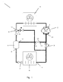
- Fig. 1 is a diagrammatic view of a vapour compression system according to an embodiment of the invention.
- Fig. 1 is a diagrammatic view of a vapour compression system 1 according to an embodiment of the invention.
- the vapour compression system 1 comprises a compressor unit 2 comprising a number of compressors 3, two of which are shown, a heat rejecting heat exchanger 4, an ejector 5, a receiver 6, an expansion device 7, in the form of an expansion valve, and an evaporator 8 arranged in a refrigerant path.
- the vapour compression system 1 further comprises a non-return valve 9 and a control valve 10.
- the receiver 6 is arranged to separate refrigerant into a liquid part and a gaseous part, and the receiver 6 comprises a liquid outlet 11 and a gaseous outlet 12.
- the liquid outlet 11 is connected to the expansion device 7, i.e. the liquid part of the refrigerant in the receiver 6 is supplied to the evaporator 8, via the expansion device 7.
- the vapour compression system 1 of Fig. 1 may be operated in the following manner. Refrigerant flowing in the refrigerant path is compressed by means of the compressors 3 of the compressor unit 2, and the compressed refrigerant is supplied to the heat rejecting heat exchanger 4. In the heat rejecting heat exchanger 4 heat exchange takes place between the refrigerant flowing through the heat rejecting heat exchanger 4 and the ambient, in such a manner that heat is rejected from the refrigerant to the ambient.
- the refrigerant is at least partly condensed, and in the case that the heat rejecting heat exchanger 4 is in the form of a gas cooler, the refrigerant is cooled, but remains in the gaseous phase.
- the refrigerant leaving the heat rejecting heat exchanger 4 is supplied to a primary inlet 13 of the ejector 5, where the refrigerant undergoes expansion before being supplied to the receiver 6.
- the refrigerant In the receiver 6 the refrigerant is separated into a liquid part and a gaseous part.
- the liquid part of the refrigerant is supplied to the expansion device 7, via the liquid outlet 11.
- the expansion device 7 expands the refrigerant before it is supplied to the evaporator 8.
- the refrigerant being supplied to the evaporator 8 is in a mixed liquid and gaseous state.
- the gaseous part of the refrigerant in the receiver 6 is supplied to an inlet 13 of the control valve 10.
- refrigerant is supplied to a part of the refrigerant path interconnecting the non-return valve 9 and an inlet 15 of the compressor unit 2.
- a refrigerant flow from the gaseous outlet 12 of the receiver 6 towards the part of the refrigerant path interconnecting the non-return valve 9 and the inlet 15 of the compressor unit 2 is controlled by means of the control valve 10.
- the liquid part of the refrigerant is at least partly evaporated, while heat exchange takes place between the refrigerant and the ambient in such a manner that heat is absorbed by the refrigerant flowing through the evaporator 8.
- the refrigerant leaving the evaporator 8 is supplied to the non-return valve 9 and/or to a secondary inlet 16 of the ejector 5.
- Refrigerant can be delivered from the evaporator 8, via the non-return valve 9, and/or from the gaseous outlet 12 of the receiver 6, passing through the control valve 10. If the pressure prevailing at the outlet 14 of the control valve 10 is higher than the pressure prevailing at the outlet 17 of the evaporator 8, the non-return 9 valve is closed. In this case, all the refrigerant at the inlet 15 of the compressor unit 2 is supplied from the gaseous outlet 12 of the receiver 6.
- the pressure prevailing in the refrigerant path interconnecting the non-return valve 9 and the inlet 15 of the compressor unit 2 relative to the pressure prevailing in the refrigerant path interconnecting the outlet 17 of the evaporator 8 depends on the pressure prevailing in the receiver 6 and to which extent the control valve 10 allows a flow across it.
- the refrigerant flow across the non-return valve 9 is determined by the pressures prevailing on either side of it. Then the flow across the non-return valve 9 and thus switching between operation according to a summer mode or a winter mode can be simply achieved by controlling the control valve 10 in an appropriate manner.
Landscapes
- Engineering & Computer Science (AREA)
- Physics & Mathematics (AREA)
- Mechanical Engineering (AREA)
- Thermal Sciences (AREA)
- General Engineering & Computer Science (AREA)
- Air-Conditioning For Vehicles (AREA)
Priority Applications (2)
| Application Number | Priority Date | Filing Date | Title |
|---|---|---|---|
| EP15169553.3A EP3098543A1 (de) | 2015-05-28 | 2015-05-28 | Dampfkompressionssystem mit einem auswerfer und einem rückschlagventil |
| PCT/EP2016/060869 WO2016188777A1 (en) | 2015-05-28 | 2016-05-13 | A vapour compression system with an ejector and a non-return valve |
Applications Claiming Priority (1)
| Application Number | Priority Date | Filing Date | Title |
|---|---|---|---|
| EP15169553.3A EP3098543A1 (de) | 2015-05-28 | 2015-05-28 | Dampfkompressionssystem mit einem auswerfer und einem rückschlagventil |
Publications (1)
| Publication Number | Publication Date |
|---|---|
| EP3098543A1 true EP3098543A1 (de) | 2016-11-30 |
Family
ID=53264580
Family Applications (1)
| Application Number | Title | Priority Date | Filing Date |
|---|---|---|---|
| EP15169553.3A Withdrawn EP3098543A1 (de) | 2015-05-28 | 2015-05-28 | Dampfkompressionssystem mit einem auswerfer und einem rückschlagventil |
Country Status (2)
| Country | Link |
|---|---|
| EP (1) | EP3098543A1 (de) |
| WO (1) | WO2016188777A1 (de) |
Cited By (8)
| Publication number | Priority date | Publication date | Assignee | Title |
|---|---|---|---|---|
| JP2016044852A (ja) * | 2014-08-21 | 2016-04-04 | 株式会社デンソー | エジェクタ、およびエジェクタ式冷凍サイクル |
| US20180283754A1 (en) * | 2015-10-20 | 2018-10-04 | Danfoss A/S | A method for controlling a vapour compression system in ejector mode for a prolonged time |
| EP3444540A3 (de) * | 2017-08-18 | 2019-05-15 | Rolls-Royce North American Technologies, Inc. | Transkritisches dampfverdichtersystem mit rückführung von wiedergewonnener überhitzung |
| US10816245B2 (en) | 2015-08-14 | 2020-10-27 | Danfoss A/S | Vapour compression system with at least two evaporator groups |
| EP3798533A1 (de) * | 2019-09-26 | 2021-03-31 | Danfoss A/S | Verfahren zur steuerung des saugdrucks eines dampfkompressionssystems |
| US11333449B2 (en) | 2018-10-15 | 2022-05-17 | Danfoss A/S | Heat exchanger plate with strengthened diagonal area |
| US11460230B2 (en) | 2015-10-20 | 2022-10-04 | Danfoss A/S | Method for controlling a vapour compression system with a variable receiver pressure setpoint |
| US11976747B2 (en) | 2019-03-20 | 2024-05-07 | Danfoss A/S | Compressor unit with a damped axial check valve for a discharge outlet |
Citations (4)
| Publication number | Priority date | Publication date | Assignee | Title |
|---|---|---|---|---|
| JP2001221517A (ja) * | 2000-02-10 | 2001-08-17 | Sharp Corp | 超臨界冷凍サイクル |
| US20040003608A1 (en) * | 2002-07-08 | 2004-01-08 | Hirotsugu Takeuchi | Ejector cycle |
| JP2010133605A (ja) * | 2008-12-03 | 2010-06-17 | Denso Corp | エジェクタ式冷凍サイクル |
| US20120167601A1 (en) | 2011-01-04 | 2012-07-05 | Carrier Corporation | Ejector Cycle |
-
2015
- 2015-05-28 EP EP15169553.3A patent/EP3098543A1/de not_active Withdrawn
-
2016
- 2016-05-13 WO PCT/EP2016/060869 patent/WO2016188777A1/en not_active Ceased
Patent Citations (4)
| Publication number | Priority date | Publication date | Assignee | Title |
|---|---|---|---|---|
| JP2001221517A (ja) * | 2000-02-10 | 2001-08-17 | Sharp Corp | 超臨界冷凍サイクル |
| US20040003608A1 (en) * | 2002-07-08 | 2004-01-08 | Hirotsugu Takeuchi | Ejector cycle |
| JP2010133605A (ja) * | 2008-12-03 | 2010-06-17 | Denso Corp | エジェクタ式冷凍サイクル |
| US20120167601A1 (en) | 2011-01-04 | 2012-07-05 | Carrier Corporation | Ejector Cycle |
Cited By (15)
| Publication number | Priority date | Publication date | Assignee | Title |
|---|---|---|---|---|
| JP2016044852A (ja) * | 2014-08-21 | 2016-04-04 | 株式会社デンソー | エジェクタ、およびエジェクタ式冷凍サイクル |
| US10816245B2 (en) | 2015-08-14 | 2020-10-27 | Danfoss A/S | Vapour compression system with at least two evaporator groups |
| US20180283754A1 (en) * | 2015-10-20 | 2018-10-04 | Danfoss A/S | A method for controlling a vapour compression system in ejector mode for a prolonged time |
| US10775086B2 (en) * | 2015-10-20 | 2020-09-15 | Danfoss A/S | Method for controlling a vapour compression system in ejector mode for a prolonged time |
| US11460230B2 (en) | 2015-10-20 | 2022-10-04 | Danfoss A/S | Method for controlling a vapour compression system with a variable receiver pressure setpoint |
| US11035595B2 (en) | 2017-08-18 | 2021-06-15 | Rolls-Royce North American Technologies Inc. | Recuperated superheat return trans-critical vapor compression system |
| EP3444540A3 (de) * | 2017-08-18 | 2019-05-15 | Rolls-Royce North American Technologies, Inc. | Transkritisches dampfverdichtersystem mit rückführung von wiedergewonnener überhitzung |
| US11333449B2 (en) | 2018-10-15 | 2022-05-17 | Danfoss A/S | Heat exchanger plate with strengthened diagonal area |
| US11976747B2 (en) | 2019-03-20 | 2024-05-07 | Danfoss A/S | Compressor unit with a damped axial check valve for a discharge outlet |
| US12467555B2 (en) | 2019-03-20 | 2025-11-11 | Danfoss A/S | Check valve damping |
| CN113825960A (zh) * | 2019-09-26 | 2021-12-21 | 丹佛斯有限公司 | 用于控制蒸气压缩系统的抽吸压力的方法 |
| WO2021058193A1 (en) * | 2019-09-26 | 2021-04-01 | Danfoss A/S | A method for controlling suction pressure of a vapour compression system |
| EP3798533A1 (de) * | 2019-09-26 | 2021-03-31 | Danfoss A/S | Verfahren zur steuerung des saugdrucks eines dampfkompressionssystems |
| CN113825960B (zh) * | 2019-09-26 | 2022-12-23 | 丹佛斯有限公司 | 用于控制蒸气压缩系统的抽吸压力的方法 |
| US12259165B2 (en) | 2019-09-26 | 2025-03-25 | Danfoss A/S | Method for controlling suction pressure of a vapour compression system |
Also Published As
| Publication number | Publication date |
|---|---|
| WO2016188777A1 (en) | 2016-12-01 |
Similar Documents
| Publication | Publication Date | Title |
|---|---|---|
| EP3098543A1 (de) | Dampfkompressionssystem mit einem auswerfer und einem rückschlagventil | |
| EP3023714B1 (de) | Verfahren zur steuerung eines dampfkompressionssystems mit einem ejektor | |
| EP3032192B1 (de) | Verfahren zur Steuerung einer Ventilanordnung in einem Dampfkompressionssystem | |
| US9612042B2 (en) | Method of operating a refrigeration system in a null cycle | |
| US10107535B2 (en) | Pressure spike reduction for refrigerant systems incorporating a microchannel heat exchanger | |
| US10816245B2 (en) | Vapour compression system with at least two evaporator groups | |
| US9816739B2 (en) | Refrigeration system and refrigeration method providing heat recovery | |
| EP3023712A1 (de) | Verfahren zur Steuerung eines Dampfkompressionssystems mit einem Empfänger | |
| EP2554411A1 (de) | Kühlsystem für ein Fahrzeug und Verfahren zur Steuerung eines Kühlsystems für ein Fahrzeug | |
| US10571156B2 (en) | Self-regulating valve for a vapour compression system | |
| US9109817B2 (en) | Air conditioner and method of operating an air conditioner | |
| KR101923770B1 (ko) | 엔진 구동식 공기 조화 장치 | |
| EP3628940B1 (de) | Verfahren zum steuern eines dampfkompressionssystems basierend auf geschätzten durchfluss | |
| US20170356681A1 (en) | Refrigeration and heating system |
Legal Events
| Date | Code | Title | Description |
|---|---|---|---|
| PUAI | Public reference made under article 153(3) epc to a published international application that has entered the european phase |
Free format text: ORIGINAL CODE: 0009012 |
|
| AK | Designated contracting states |
Kind code of ref document: A1 Designated state(s): AL AT BE BG CH CY CZ DE DK EE ES FI FR GB GR HR HU IE IS IT LI LT LU LV MC MK MT NL NO PL PT RO RS SE SI SK SM TR |
|
| AX | Request for extension of the european patent |
Extension state: BA ME |
|
| STAA | Information on the status of an ep patent application or granted ep patent |
Free format text: STATUS: THE APPLICATION IS DEEMED TO BE WITHDRAWN |
|
| 18D | Application deemed to be withdrawn |
Effective date: 20170531 |