EP3098680A1 - Procédé et machine-outil avec plusiers outils de usinage - Google Patents
Procédé et machine-outil avec plusiers outils de usinage Download PDFInfo
- Publication number
- EP3098680A1 EP3098680A1 EP16171676.6A EP16171676A EP3098680A1 EP 3098680 A1 EP3098680 A1 EP 3098680A1 EP 16171676 A EP16171676 A EP 16171676A EP 3098680 A1 EP3098680 A1 EP 3098680A1
- Authority
- EP
- European Patent Office
- Prior art keywords
- processing
- workpiece
- machine tool
- control
- control device
- Prior art date
- Legal status (The legal status is an assumption and is not a legal conclusion. Google has not performed a legal analysis and makes no representation as to the accuracy of the status listed.)
- Withdrawn
Links
Images


Classifications
-
- G—PHYSICS
- G05—CONTROLLING; REGULATING
- G05B—CONTROL OR REGULATING SYSTEMS IN GENERAL; FUNCTIONAL ELEMENTS OF SUCH SYSTEMS; MONITORING OR TESTING ARRANGEMENTS FOR SUCH SYSTEMS OR ELEMENTS
- G05B19/00—Program-control systems
- G05B19/02—Program-control systems electric
- G05B19/418—Total factory control, i.e. centrally controlling a plurality of machines, e.g. direct or distributed numerical control [DNC], flexible manufacturing systems [FMS], integrated manufacturing systems [IMS] or computer integrated manufacturing [CIM]
- G05B19/41865—Total factory control, i.e. centrally controlling a plurality of machines, e.g. direct or distributed numerical control [DNC], flexible manufacturing systems [FMS], integrated manufacturing systems [IMS] or computer integrated manufacturing [CIM] characterised by job scheduling, process planning, material flow
-
- B—PERFORMING OPERATIONS; TRANSPORTING
- B23—MACHINE TOOLS; METAL-WORKING NOT OTHERWISE PROVIDED FOR
- B23Q—DETAILS, COMPONENTS, OR ACCESSORIES FOR MACHINE TOOLS, e.g. ARRANGEMENTS FOR COPYING OR CONTROLLING; MACHINE TOOLS IN GENERAL CHARACTERISED BY THE CONSTRUCTION OF PARTICULAR DETAILS OR COMPONENTS; COMBINATIONS OR ASSOCIATIONS OF METAL-WORKING MACHINES, NOT DIRECTED TO A PARTICULAR RESULT
- B23Q39/00—Metal-working machines incorporating a plurality of sub-assemblies, each capable of performing a metal-working operation
- B23Q39/02—Metal-working machines incorporating a plurality of sub-assemblies, each capable of performing a metal-working operation the sub-assemblies being capable of being brought to act at a single operating station
- B23Q39/021—Metal-working machines incorporating a plurality of sub-assemblies, each capable of performing a metal-working operation the sub-assemblies being capable of being brought to act at a single operating station with a plurality of toolheads per workholder, whereby the toolhead is a main spindle, a multispindle, a revolver or the like
- B23Q39/022—Metal-working machines incorporating a plurality of sub-assemblies, each capable of performing a metal-working operation the sub-assemblies being capable of being brought to act at a single operating station with a plurality of toolheads per workholder, whereby the toolhead is a main spindle, a multispindle, a revolver or the like with same working direction of toolheads on same workholder
- B23Q39/023—Metal-working machines incorporating a plurality of sub-assemblies, each capable of performing a metal-working operation the sub-assemblies being capable of being brought to act at a single operating station with a plurality of toolheads per workholder, whereby the toolhead is a main spindle, a multispindle, a revolver or the like with same working direction of toolheads on same workholder simultaneous working of toolheads
-
- B—PERFORMING OPERATIONS; TRANSPORTING
- B23—MACHINE TOOLS; METAL-WORKING NOT OTHERWISE PROVIDED FOR
- B23Q—DETAILS, COMPONENTS, OR ACCESSORIES FOR MACHINE TOOLS, e.g. ARRANGEMENTS FOR COPYING OR CONTROLLING; MACHINE TOOLS IN GENERAL CHARACTERISED BY THE CONSTRUCTION OF PARTICULAR DETAILS OR COMPONENTS; COMBINATIONS OR ASSOCIATIONS OF METAL-WORKING MACHINES, NOT DIRECTED TO A PARTICULAR RESULT
- B23Q39/00—Metal-working machines incorporating a plurality of sub-assemblies, each capable of performing a metal-working operation
- B23Q39/04—Metal-working machines incorporating a plurality of sub-assemblies, each capable of performing a metal-working operation the sub-assemblies being arranged to operate simultaneously at different stations, e.g. with an annular work-table moved in steps
-
- B—PERFORMING OPERATIONS; TRANSPORTING
- B23—MACHINE TOOLS; METAL-WORKING NOT OTHERWISE PROVIDED FOR
- B23Q—DETAILS, COMPONENTS, OR ACCESSORIES FOR MACHINE TOOLS, e.g. ARRANGEMENTS FOR COPYING OR CONTROLLING; MACHINE TOOLS IN GENERAL CHARACTERISED BY THE CONSTRUCTION OF PARTICULAR DETAILS OR COMPONENTS; COMBINATIONS OR ASSOCIATIONS OF METAL-WORKING MACHINES, NOT DIRECTED TO A PARTICULAR RESULT
- B23Q2240/00—Machine tools specially suited for a specific kind of workpiece
- B23Q2240/007—Elongated workpieces
-
- Y—GENERAL TAGGING OF NEW TECHNOLOGICAL DEVELOPMENTS; GENERAL TAGGING OF CROSS-SECTIONAL TECHNOLOGIES SPANNING OVER SEVERAL SECTIONS OF THE IPC; TECHNICAL SUBJECTS COVERED BY FORMER USPC CROSS-REFERENCE ART COLLECTIONS [XRACs] AND DIGESTS
- Y02—TECHNOLOGIES OR APPLICATIONS FOR MITIGATION OR ADAPTATION AGAINST CLIMATE CHANGE
- Y02P—CLIMATE CHANGE MITIGATION TECHNOLOGIES IN THE PRODUCTION OR PROCESSING OF GOODS
- Y02P90/00—Enabling technologies with a potential contribution to greenhouse gas [GHG] emissions mitigation
- Y02P90/02—Total factory control, e.g. smart factories, flexible manufacturing systems [FMS] or integrated manufacturing systems [IMS]
Definitions
- the invention relates to a machine tool and method for controlling a machine tool.
- the invention relates to a machine tool for machining a workpiece, in particular a profile carrier, comprising at least first and second processing means, a guide means for guiding or holding the first and second processing means, at least one clamping device for clamping the workpiece during processing by the first and second processing means , and a control device for controlling the machine tool.
- Such machine tools are known from the prior art and allow the fully automated processing of profile carriers.
- the aim is generally to achieve the shortest possible processing time. This goal can be achieved by parallel steps.
- Out DE 10 2009 019 267 A1 is a machine tool for machining profiled bars, which has a holding device for holding the profiled bars, a processing device, and a guide device, wherein the processing device is movable along the guide device and comprises both a separating device such as a saw, as well as a drilling or milling device.
- EP 2 641 681 B1 a machine tool is known, which is formed from a composite of a fixed portal, which includes a saw and another fixed portal, which includes a drilling / milling device.
- the present invention has an object to further reduce the processing time.
- the first machining device is movable along the guide device and relative to the second machining device.
- Such a machine tool is used in particular for processing large workpieces, ie workpieces that can be several meters long. For example, when machining, you should drill and saw. These processing steps can be done by the first and the second Machining device to be performed. Advantageously, these processing steps can be performed at least partially in parallel. This results in a shorter machining time per workpiece.
- An advantage of the invention is that the operations by the first and second processing means (e.g., drilling and sawing) are decoupled from each other, at least spatially. Depending on the workpiece machining to be performed, no re-clamping of the workpiece is required to carry out the individual machining steps. In other words, the workpiece only needs to be clamped once. This results in the suitability for parallel processing of the workpiece.
- first and second processing means e.g., drilling and sawing
- control device is designed to control the processing of the first workpiece or a second workpiece by the first processing device, wherein the first processing device during the parallel processing step along the guide device is moved relative to the second processing device.
- the machine tool comprises one or more further processing devices, which are each movable relative to the guide device and relative to the second processing device, wherein the control device is adapted, during the processing of a first workpiece by the second Machining device to control a simultaneous processing of the first workpiece or a second workpiece by the further processing means, wherein the further processing means is moved along the guide means relative to the second processing means.
- the invention enables the parallel machining of workpieces by a plurality of processing devices.
- the first processing device and / or, if appropriate, the further processing devices can each be designed for processing the workpiece with at least one rotatable tool and / or the second processing device for cutting the workpiece.
- the second processing device is the foremost processing device in the feed direction of the workpiece and stationary.
- a workpiece first passes the first processing device and optionally subsequently the further processing devices, and finally the stationary second processing device. If one of the processing devices is formed by a saw, then it is preferably the fixed, second processing device.
- the first processing device is formed by a portal movable along the guide device, wherein the portal comprises a plurality of receiving devices for a rotatable tool or a separating tool.
- the portal can be moved along the guide device to a point at the one or more processing steps, for example Drilling, to be performed.
- machining can be carried out virtually anywhere on the workpiece while sawing at one end of the workpiece.
- the rotatable tools may each be movable relative to the portal and / or relative to each other.
- processing steps can be carried out at different positions within a workspace defined by the movement space of the rotatable tools.
- processing steps can be carried out on the one hand within the workspace of the portal, namely with a stationary portal, and on the other to places that would lie in an immobile portal outside the work area.
- processing steps can be carried out on the one hand within the workspace of the portal, namely with a stationary portal, and on the other to places that would lie in an immobile portal outside the work area.
- the machine tool comprises a first and a second feed carriage for advancing a workpiece along the guide means, wherein the first and second feed carriage are movable relative to each other and independently controllable.
- first feed carriage With the first feed carriage, a first workpiece can be transported to the sawing device and fixed. During machining of the first workpiece, the first feed carriage remains in its position. Meanwhile, a second feed carriage may already carry the next workpiece towards the processing stations.
- the Feed carriage allows multiple workpieces to be machined simultaneously, eg, sawing the first workpiece while already drilling on the second workpiece.
- the design of the feed carriage allows feed carriage and located in the machining position workpiece collision in the longitudinal direction can pass each other. To...
- the machine tool may have a workpiece feed device for feeding a workpiece to the first feed carriage in a direction transversely, in particular perpendicular to the guide device.
- a machine tool configured in this way enables the feeding of another workpiece, while a previously supplied workpiece is still being processed.
- the clamping device comprises one or more vices for clamping a workpiece in a processing position, wherein the vices are movable relative to each other and / or relative to the first and / or second processing means and / or independently controllable. Due to the mobility of the vices, it is possible to avoid potential collisions between the processing equipment, in particular the movable portal and the vices.
- processing devices are each designed as a portal, and the feed carriage and / or the vices are designed such that they are movable through the portals.
- the movable processing devices, the feed cars and the vices can be moved relative to each other, without causing collisions.
- the machine tool comprises a Measuring device for measuring one or more predetermined parameters of workpiece machining, wherein the control device is adapted to change an order of processing steps by the first and / or second processing device depending on measurement results of the measuring device.
- This embodiment is particularly advantageous when there are differences between a planned duration of a processing step and an actual duration of the processing step. Such differences may arise due to variations in the material properties of the workpiece or due to wear of the machining tools. For example, it may be provided for the execution of a hole a period of 5 sec, while the measurement shows that the hole is completed only after 8 sec. In such a case, it may be convenient to adjust the order of the processing steps.
- the second processing device comprises a saw
- / or the at least one rotatable tool comprises at least one drill.
- the invention is not limited to the implementation of holes or saws. Instead of or in addition to drilling, other operations may be performed, e.g. Milling, sinking, etc. In place of or in addition to sawing, other cutting operations may be performed, e.g. a thermal separation or notching.
- a method of controlling the machine tool comprising: receiving, by the control means, parameters relating to workpieces to be machined and intended operations on the workpieces; Determining, by the controller, based on the received Parameter, a sequence of processing steps, wherein the processing steps are performed at least partially simultaneously by the first and / or optionally further processing means and the second processing means; and generating, by the control device, control signals for the workpiece feed device, the first and / or second feed devices, and / or the processing devices, for carrying out the processing steps in the specific sequence.
- a significant advantage of this method is that the order of the processing steps can be set differently.
- the method can be implemented in particular by software for controlling the machine tool.
- software allows e.g. is entered into an operating terminal of the machine tool, as the finished workpiece has to look.
- the software determines which work steps are performed in which order. Subsequently, the software provides so-called CNC data.
- the software is designed in such a way that collisions (for example between work spindles and vices) are prevented during the determination of the sequence of the processing steps and, at the same time, as fast as possible, i. parallel processing may take place or that the routes of the processing facilities, in particular the portal and the rotatable tools are as small as possible.
- the method comprises adjusting, by the control device, the order of the processing steps in response to a change in the parameters or the receipt of new parameters during Workpiece machining; and generating, by the controller, new control signals according to the adjusted order.
- the parameters may include information about dimensions of the workpieces, nature of the intended operations, and location of intended operations, which method may include the following further steps: determining, by the controller, the nature of the workings envisaged, depending on the dimensions of the workpieces and the position of the intended operations, a first order in which the workpieces are processed, and a second order of processing steps to be performed by the first and second processing means; and generating, by the control device, control signals for the workpiece feed device, the first and / or second feed devices, and / or the first and / or second processing devices for performing the workpiece processing according to the first and second orders.
- the sequence of processing steps thus results from the information about the workpiece to be machined, in particular its dimensions, as well as the product to be produced.
- it can access a database in which certain information is stored, such as the duration for making a hole through a workpiece of a certain size and from a specific material.
- control device controls the first processing device such that during the processing of one of the workpieces by the second processing device optionally a simultaneous processing of the same or another workpiece takes place.
- the control device can control the processing devices such that the first and / or optionally the further processing devices are moved during the workpiece processing by the second processing device relative to the second processing device and relative to each other.
- the processing devices can control the processing devices such that the first and / or optionally the further processing devices are moved during the workpiece processing by the second processing device relative to the second processing device and relative to each other.
- u.U. Holes are made relatively far apart while a sawing operation is being performed in parallel at another location.
- the method first comprises a control, by the control device, the first processing device and / or, if appropriate, the further processing devices for carrying out all processing which is within a predetermined distance from a designated position for processing by the second processing device; thereafter, a controller, by the control means, the feed means for displacing the workpiece so that the second processing means is disposed at the intended position; and thereafter a control, by the control means, the second processing means for processing the workpiece at the intended position and the first processing means for simultaneously processing the workpiece at at least one position outside the predetermined distance from the intended position lies.
- first holes can be made, which are close to a designated SAgeposition, after which more distant holes are then performed in parallel to the subsequent sawing. In this way, collisions can be avoided and yet a parallelization of the workpiece machining can be achieved.
- the method comprises determining, by the control device, a third sequence of processing steps to be performed by the rotatable tools of the first processing device, wherein these processing steps include a movement of the rotatable tools within the portal may include, but require no movement of the first processing device relative to the second processing device.
- it is first determined in which order several workpieces are to be processed, and in which order the first and second processing devices are used, before it is determined in which order the processing steps are performed by the rotatable tools of the portal.
- Such a hierarchical determination of the orders has proven to be efficient.
- the method comprises determining, by the control device, by means of measurement data supplied by a measuring device, whether a workpiece fed for processing into the machine tool corresponds to the next workpiece to be machined according to the determined first order; and if the supplied workpiece does not correspond to the next workpiece to be processed, determining, by the controller, whether the supplied workpiece corresponds to a workpiece to be machined later and, if the supplied workpiece corresponds to a workpiece to be machined later, the adjusting, by the control device, at least the first order.
- the method comprises determining, by the control device, based on the position of a currently machined workpiece, whether the next workpiece can be fed to the machine tool and, if appropriate, controlling by the control device, the workpiece feed device, so that the machine tool provides the next one Workpiece is supplied.
- the method comprises determining, by the control device, during the processing of a workpiece by the second processing device, whether at least one further processing step not yet provided at that time by the first and / or optionally the further processing devices at least partially simultaneously with the processing the workpiece can be performed by the second processing device, and optionally a controller, by the control device, the first and / or optionally further processing means for at least partially simultaneous execution of the further processing step.
- This embodiment allows an adaptation of the processing to detected changes, eg due to premature termination of a Machining step.
- the method comprises measuring, by the control device, the duration for the execution of one or more of the processing steps by the first and / or second and / or optionally further processing devices; comparing, by the controller, the measured values with stored values underlying the determination of the first, second and / or third orders; and adjusting, by the controller, the first and / or second and / or third order, depending on the result of the comparison.
- measurements are taken and taken into account during the execution of the individual work steps. These measurements are taken into account in performing the operations, i. Depending on the measurements, a change in the sequence of work steps may occur. For example. such a measurement may indicate that the drilling takes longer than anticipated, i. longer than calculated from information in a database. In such a case, it may happen that, for example, the affected holes are later carried out, because they can not be performed parallel to a sawing step also to be performed due to the longer time. Instead, other (shorter) operations may be performed in parallel to the sawing step.
- a control device is additionally provided which is set up or programmed for carrying out the method described above.
- a computer program comprising machine-readable instructions which, when executed by a computer-implemented controller, cause execution of the method described above.
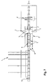
- FIG. 1 shows a machine tool 1 according to an exemplary embodiment of the invention with a guide device 2, a (first) processing device (3), a separator 4 (second Processing device) and two along the guide device 2 displaceable vices 5.
- the separating device 4 is arranged at one end of the guide device 2 such that the separating device 4 delimits the guide device 2.
- the separator 4 is formed by a fixed portal, which includes a saw, in particular a band saw, or a thermal separator.
- the processing device 3 and the tensioning rods 5 are displaceable along the guide device 2 both relative to one another and relative to the fixed separating device 4.
- the guide device 2 is designed to guide and receive the tensioning rods 5 and the machining device 3. For this purpose, corresponding guide rails 8 are provided along the guide device 2.
- the processing device 3 is, like the separator, designed as a portal.
- the vices 5 can be placed within the portal, i. be moved through the portal and allow the fixed clamping and transporting the workpieces.
- the processing device 3 comprises according to the illustrated embodiment, three rotatable tools. But it can also be any other tools such as punching, stamping or marking tools use.
- the tools are arranged so that they are movable within the processing device 3, which can be used, for example, to summarize work steps, for example, to form Bohrnester.
- the rotatable tools can be movable both in the direction of the guide rails 8 of the guide device 2 and also transversely to the guide device 2 and along the vertical axis of the processing device 3.
- the rotatable tools can thus move independently in all three spatial directions within the dimensions of the processing device 3, whereby a displacement of the processing device 3 can be minimized by grouping processes lying close to one another. If the processing steps are within the range of the portal of the processing device in which the rotatable tools are movable, a control device (not shown) calculates a position of the processing device 3 to form groups such that the travel path of the processing device 3 is minimized.
- the receiving means for the rotatable tools 7 of the processing device 3 are movable within the portal.
- the portal can have further guide rails for the receiving devices of the rotatable tools.
- the separator 4 may be provided with an additional clamping and / or miter 6 for miter sawing workpieces.
- the separator 4 is in the illustrated embodiment by a saw, for example, a band saw formed.
- the separator 4 may be implemented by a thermal separator, such as a cutting torch or a laser.
- the dimensions of the separating device, in particular the portal width can be adapted to the dimensions of the workpieces to be machined.
- a discharge device for the separating waste is provided behind the separator 4.
- the discharge device can be combined with a transport device for the removal of the residual pieces and / or the finished parts.
- the control device is designed to control the separating device 4, the processing device 3, the rotatable tools, the tensioning rods 5 and a plurality of measuring or feed carriages 9, 10 in a process-optimal manner and independently of one another.
- the control device is in particular designed to minimize the travel paths of the moving parts along the guide device 2.
- a transverse transport system is provided in the region of the machine opposite the separating device 4, that is to say in the feed region of the workpieces.
- a workpiece is brought into the feed region, ie the free region of the guide device 2 or a region of the guide device 2 or a region in front of the guide device 2, via the transverse transport device. It already comes on lie to the movable vices 5 and is biased and the front side detected by a measuring carriage 9,10.
- the measuring carriage 9, 10 determines a material zero point and feeds the workpiece to the separating device 4.
- a plurality of measuring or feed carriages 9, 10 are provided in order to measure and / or supply a plurality of workpieces in parallel.
- the controller calculates, e.g. according to the instructions of the operator, how the workpiece is to be processed and which work steps are executed in which order.
- transverse transport beams of the transverse transport system can be folded up.
- the workpiece of the separator 4 is supplied, it is clamped by the miter 6 and the movable vices 5.
- the position of the vices 5 is determined by the controller so that a collision with the processing device 3 is avoided. In this case, changes in position of the processing device 3 are taken into account during the machining of the workpiece from the outset. In other words, the tensioning rods 5 are positioned by the control device so that they do not stand in the way of the processing device 3 during the subsequent processing.
- the processing device 3 can execute several or even all of the work steps to be performed by it in parallel.
- the working steps of the processing device 3 are decoupled both spatially and temporally from the separation process.
- the controller calculates the optimal sequence of operations as Minimization problem of the processing time depending on the path of the processing device 3. It can be summarized by the processing device 3 processing steps due to the mobility of the tools within the processing device 3 in subgroups summarized (so-called Bohrnester, see above).
- the removal / continuation is carried out by the movable vices 5 and the measuring carriage 9,10. If two workpieces are machined in parallel, the tensioning rods 5 are, if necessary, controlled during a machining operation in such a way that encompassing is effected in order to prevent collisions with the machining device 3.
- the measuring carriages 9, 10 and the tensioning rods 5 return to a starting position in the region of the material feed in order to receive one or more new workpieces.
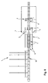
- FIG. 2 shows an exemplary embodiment of the invention in a plan view.
- the separator 4 forms in this view, a right boundary of the guide device.
- the guide device 2 comprises a plurality of guide rails 8 for receiving the tensioning rods 5, the machining device 3 and further components movable along the guide device 2, for example feed or measuring carriages 9, 10.
- the vices 5 have a smaller width or a smaller cross-section than the opening of the portal, so that the vices can be moved through the portal opening therethrough. Thus, the vices 5 can be moved independently of the position or decoupled from the processing device 3.
- further guide rails for receiving, for example, measuring carriage 9 and / or other vices can be provided. It is also possible to arrange several tensioning rods 5 or measuring carriages 9, 10 on the guide rails 8 so as to be displaceable parallel to one another. This allows simultaneous machining of multiple workpieces.
- the vices 5 can be designed so that a grip on the workpiece during processing is possible. As a result, collisions can be avoided.
- the receiving devices for the rotatable tools of the processing device 3 as trolleys, which are mounted by means of guide rails on the portal of the processing device 3 executed.
- FIG. 3 shows a side view of the machine tool 1.
- the tensioning rods 5 are displaceable within the portal width of the processing device 3, ie through the portal opening.
- the vices 5 can be designed so that workpieces within can be moved transversely to the longitudinal extent of the guide rails defined by the portal width of the processing device 3 boundaries. This has the advantage that several workpieces can be clamped and processed in parallel. Thus, the cutting operation and the machining operation can not only take place in parallel / simultaneously on a workpiece, but also in parallel on different workpieces within the same machine. It is thus possible an additional decoupling of separation and machining operations. This allows for further time savings and leads to better utilization of the machine.
- FIG. 3 shows FIG. 3 the receiving means 7 for the rotatable tools of the processing device 3.
- the receiving means 7 are mounted on the outer sides of the portal and movable in guide rails along the outer sides. In this way, it is possible to carry out a plurality of processing steps, for example drilling, milling or grinding, without further movement of the processing device 3, if the processing points are within a predetermined range within which the rotatable tools are movable in the guide rails on the portal. Since the receiving devices for the rotatable tools can be moved independently, a further parallelization of steps is possible.
- FIG. 4 shows a flowchart with steps performed by a method according to an embodiment of the invention.
- a control software of the control device provided for implementing the method first loads a process list after the start.
- the process list forms characteristics of the product to be produced and the necessary steps from.
- Features can be taken from the digital process chain or entered by the operator.
- the inputs of the operator form an input of the control software.
- the derivation of the necessary processing steps is carried out by the control software.
- the sorting of the machining order includes sorting the machining ascending along the material feeding direction, assigning the machining to the machines depending on the work area, and grouping them (e.g., forming nests). Furthermore, the sorting of the processing includes determining the timing and setting the processing positions. Thereafter, the machine / component positions are calculated and the order of processing in the processing nests is determined.
- defining the order of the operations further includes the assignment of the machining operations to the axes of the machines, further sorting the machining operations in descending order of the sensitivity of the tool, identifying potential collisions and conflicts, and adjusting the order to avoid them, as well as creating of CNC programs.
- a feature of the control software is that the order of the processing steps can be set differently.
- the order of the processing steps results from information on the workpiece to be machined (process list, see above), in particular its dimensions, and the product to be produced.
- the software accesses a database in certain information is stored, such as the duration for making a hole through a workpiece of a certain size and from a particular material.
- the control software allows the implementation of different, possibly also variable sequences of steps.
- Another feature of the control software is that measurements are taken and taken into account during the execution of the individual work steps. These measurements are taken into account in performing the operations, i. Depending on the measurements, a change in the sequence of work steps may occur. For example, such a measurement may indicate that the execution of a well is taking longer than expected, i. longer than calculated from the information in the database. In such a case, it may happen that, for example, the corresponding holes are made later, because they can not be performed in parallel to a saw cut also to be performed due to the longer time. Instead, other operations may be performed in parallel with the saw cut.
- the raw material is loaded. If this has already been done, the raw material is checked and, if necessary, unintended material unloaded. If provided material is loaded, the control device checks whether the calculated processing positions are free. According to the sorted processing sequence, free machines / components are already positioned and prepared for processing.
- the controller positions and tensions the loaded material for processing. While now the Processing begins, the control device already checks whether new, later required material can be supplied. If the supply is free, a second control entity is started by which a processing of the newly supplied workpiece is made possible in parallel to the processing of the previous workpiece. If the feeder is not free, the loaded material will be processed first without feeding new material.
- the processing of the material includes the positioning of the processing facilities, the loading of the processing data and the processing of the processing. If all processing according to the process list is executed, the control device checks whether further processing can be carried out. This is always done as an intermediate step after each edit. If other machines are still working on the material, the control device checks whether further processing steps can be carried out during the remaining time. If this is the case, there is a repositioning of the processing facilities and further processing. If the remaining processing time is not sufficient, the control device checks whether the machining operations can also be carried out after the material feed, ie in the next working cycle. If this is the case, the missing processing steps are assigned to the next cycle. If this is not the case, a cycle may need to be lengthened and the corresponding processing device is brought into the processing position. If the material is completed after the processing cycle, it is relaxed and discharged.
- control device checks whether a re-tightening is necessary. Thereafter, the material is optionally relaxed and re-clamped.
- FIGS 5-8 show schematically using an embodiment of the machine tool according to the invention an exemplary sequence of the method according to the invention.
- an order consists of 3 profile carriers as raw materials, from which two parts are to be manufactured with holes at the beginning and end.
- the control device requests the process list of the first material in the order.
- the process list as described above, essentially contains information about which source material is used and what operations are to be performed on the material where.
- An order can contain any number of (raw) materials.
- individual parts can be made from the raw material in steel construction by separating processes after all the workings have been carried out on the respective parts, e.g. Drilling holes, millings, notches, markings).
- the controller determines from the data the required material and requests it from a material supply system (if not already loaded) and then waits for completion of the payload, as in FIG. 5 shown.
- the processing contained in the process list sorted by the control device first according to the material feed direction. For example, the following sequence of processing steps can be determined: Saw cut, holes, holes, saw cut, holes, holes, saw cut.
- the saw cuts of the saw 4 and the machining operations (borings) are assigned to a machining center 3 forming the drilling center 3, wherein the drilling center has 600 mm working area in the material feed direction, so that bores which are not more than 600 mm apart, through the drilling center can be made without this must be moved.
- Drill holes that apply are grouped together ("drill holes").
- the control device Based on the material positions, the control device then calculates the positions of the movable components 3, 5 (eg vise positions, gantry positions). Then the motion sequences for the individual components are determined. Drill holes are checked separately. After that, the components are already in brought the calculated positions. Subsequently or during this time, the material to be processed is fed. When the material is fed, the feed system is activated. The material is measured and checked whether the dimensions correspond to the specifications received from the controller. If this is not the case, the control device checks whether the detected material is contained in the active order and prefers it in the sequence. If this is not possible, the material will be unloaded and the correct material will be requested again.
- the positions of the movable components 3, 5 eg vise positions, gantry positions.
- the control device automatically checks whether components are already available that can be prepositioned. As soon as the material is in the machining position, it is tensioned and thus fixed in place. Subsequently, the first processing cycle begins, shown in FIG. 6 , At the same time, the control unit checks whether the feeder is already free again and the next material (if available / needed) can already be loaded.
- the holes that are in close proximity to the first intended saw cut are produced in a first cycle. For example, first the side holes and then the hole are made in the web.
- measurements are carried out continuously during the drilling process, which compares the control device with data stored in a database. If deviations occur, the control device is designed to adapt the processing accordingly.
- the controller checks if the machining of the workpiece is completed.
- both processing devices 3, 4 are used, i. it is a drilling and sawing provided.
- the drilling center 3 according to the in FIG. 4 shown flowchart brought into working position. Then the first three holes (one hole per tool) are made. For this purpose, the drilling center loads a CNC program with instructions for the execution of the machining.
- the machine tool 1 is designed to check, after the execution of compulsory edits in one cycle, whether further processing is still to be carried out in the same cycle. If this is the case, the control device checks the remaining processing time (s) of the other component (s), in particular the saw 4. Subsequently, the control device determines whether it is possible in terms of time and geometry to carry out further processing. If necessary, this is caused by the control device.
- the saw 4 After completion of the processing in the second cycle, the saw 4 has a carrier start (waste) separated. This is now removed, after which the material feed is made to the next processing position for a third cycle.
- the third bar is in FIG. 8 shown and includes sawing (separation of a first finished part) and drilling at the end of a second finished part. Once the sawing has been completed, the first finished part is produced and removed. All holes for the second finished part are also made after the third cycle, so that the machining of the first workpiece is completed by the drilling center. The drilling center is thus available for processing the next workpiece / raw material.
- machining takes place on the second workpiece (second control instance) and the rear cut on the first workpiece (first control instance). After the rear cut, the second workpiece is completely processed and is discharged together with the remaining piece, whereupon the first control instance is terminated.
- the first measuring carriage 9 is now free and pulls back a gripper so that it can drive past the second workpiece and detach the second measuring carriage 10 at its end.
- the second measuring carriage is then ready for a third workpiece.
- the further process is a (multiple) repetition of the procedure described until all finished parts are made and the last remaining piece is removed. Then the automatic process / program ends.
Landscapes
- Engineering & Computer Science (AREA)
- Mechanical Engineering (AREA)
- General Engineering & Computer Science (AREA)
- Manufacturing & Machinery (AREA)
- Quality & Reliability (AREA)
- Physics & Mathematics (AREA)
- General Physics & Mathematics (AREA)
- Automation & Control Theory (AREA)
- Numerical Control (AREA)
Applications Claiming Priority (1)
| Application Number | Priority Date | Filing Date | Title |
|---|---|---|---|
| DE102015108531.3A DE102015108531A1 (de) | 2015-05-29 | 2015-05-29 | Werkzeugmaschine und Verfahren zur Steuerung einer Werkzeugmaschine |
Publications (1)
| Publication Number | Publication Date |
|---|---|
| EP3098680A1 true EP3098680A1 (fr) | 2016-11-30 |
Family
ID=56119303
Family Applications (1)
| Application Number | Title | Priority Date | Filing Date |
|---|---|---|---|
| EP16171676.6A Withdrawn EP3098680A1 (fr) | 2015-05-29 | 2016-05-27 | Procédé et machine-outil avec plusiers outils de usinage |
Country Status (2)
| Country | Link |
|---|---|
| EP (1) | EP3098680A1 (fr) |
| DE (1) | DE102015108531A1 (fr) |
Cited By (1)
| Publication number | Priority date | Publication date | Assignee | Title |
|---|---|---|---|---|
| CN114434160A (zh) * | 2022-02-08 | 2022-05-06 | 左家知 | 一种5g通信天线生产用加工装置及其加工方法 |
Families Citing this family (2)
| Publication number | Priority date | Publication date | Assignee | Title |
|---|---|---|---|---|
| DE102024122993A1 (de) * | 2024-08-12 | 2026-02-12 | Broetje-Automation Gmbh | Bearbeitungsstation |
| DE102024122994A1 (de) * | 2024-08-12 | 2026-02-12 | Broetje-Automation Gmbh | Bearbeitungsmaschine für Strukturbauteile, insbesondere Flugzeugstrukturbauteile |
Citations (7)
| Publication number | Priority date | Publication date | Assignee | Title |
|---|---|---|---|---|
| US5358018A (en) * | 1993-10-07 | 1994-10-25 | Holbert John C | Pole framing apparatus |
| DE69828671T2 (de) * | 1997-03-15 | 2006-05-11 | Makino Milling Machine Co. Ltd. | Prozessor für maschinelle bearbeitung |
| DE102006021946A1 (de) * | 2006-05-11 | 2007-11-15 | Robert Bosch Gmbh | Werkzeugmaschine zur Bearbeitung von Werkstücken, insbesondere zum Schleifen von Werkstücken |
| EP2127829A1 (fr) * | 2008-05-31 | 2009-12-02 | HOLZMA Plattenaufteiltechnik GmbH | Installation de distribution de plaques |
| DE102009019267A1 (de) | 2009-04-28 | 2010-11-04 | Mubea Systems, S.A. | 4-Achsen-Werkzeugmaschine |
| DE102011053729A1 (de) * | 2011-09-16 | 2013-03-21 | Mauser-Werke Oberndorf Maschinenbau Gmbh | Werkzeugmaschine |
| EP2641681B1 (fr) | 2012-03-21 | 2014-10-29 | Ficep S.P.A. | Dispositif de perçage pour percer des parties latérales de grands profilés |
-
2015
- 2015-05-29 DE DE102015108531.3A patent/DE102015108531A1/de not_active Withdrawn
-
2016
- 2016-05-27 EP EP16171676.6A patent/EP3098680A1/fr not_active Withdrawn
Patent Citations (7)
| Publication number | Priority date | Publication date | Assignee | Title |
|---|---|---|---|---|
| US5358018A (en) * | 1993-10-07 | 1994-10-25 | Holbert John C | Pole framing apparatus |
| DE69828671T2 (de) * | 1997-03-15 | 2006-05-11 | Makino Milling Machine Co. Ltd. | Prozessor für maschinelle bearbeitung |
| DE102006021946A1 (de) * | 2006-05-11 | 2007-11-15 | Robert Bosch Gmbh | Werkzeugmaschine zur Bearbeitung von Werkstücken, insbesondere zum Schleifen von Werkstücken |
| EP2127829A1 (fr) * | 2008-05-31 | 2009-12-02 | HOLZMA Plattenaufteiltechnik GmbH | Installation de distribution de plaques |
| DE102009019267A1 (de) | 2009-04-28 | 2010-11-04 | Mubea Systems, S.A. | 4-Achsen-Werkzeugmaschine |
| DE102011053729A1 (de) * | 2011-09-16 | 2013-03-21 | Mauser-Werke Oberndorf Maschinenbau Gmbh | Werkzeugmaschine |
| EP2641681B1 (fr) | 2012-03-21 | 2014-10-29 | Ficep S.P.A. | Dispositif de perçage pour percer des parties latérales de grands profilés |
Cited By (1)
| Publication number | Priority date | Publication date | Assignee | Title |
|---|---|---|---|---|
| CN114434160A (zh) * | 2022-02-08 | 2022-05-06 | 左家知 | 一种5g通信天线生产用加工装置及其加工方法 |
Also Published As
| Publication number | Publication date |
|---|---|
| DE102015108531A1 (de) | 2016-12-01 |
Similar Documents
| Publication | Publication Date | Title |
|---|---|---|
| EP2143524B1 (fr) | Dispositif de transport d'une pièce usinée | |
| DE102008032160B4 (de) | Verfahren zum Aufteilen plattenförmiger Werkstücke, sowie Plattenaufteilanlage | |
| EP0988924B1 (fr) | Machine pour travailler le bois | |
| DE3510381C2 (de) | Vorrichtung und Verfahren zum Bearbeiten von Werkstücken, insbesondere zum thermischen Trennen von Profilen | |
| DE202006020904U1 (de) | Werkzeugmaschine | |
| EP2285522A1 (fr) | Machine d'usinage au laser avec espace de travail étendu | |
| DE202010017997U1 (de) | Vorrichtung zum Erkennen und Korrigieren von Fehlstellen in Holz | |
| EP3296059A1 (fr) | Changeur de palettes et procédé de traitement d'un matériau en forme de plaque disposé sur une palette déplaçable | |
| DE2535202A1 (de) | Werkzeugmaschine und verfahren zur bearbeitung von werkstuecken | |
| DE19741163C2 (de) | Verfahren und Vorrichtung zur Durchlaufbearbeitung von plattenförmigen Werkstücken | |
| EP0967038B1 (fr) | Dispositif d' usinage de pièces par enlèvement de matière | |
| EP2193895B1 (fr) | Installation de découpe de plaques et son procédé de fonctionnement | |
| EP3098680A1 (fr) | Procédé et machine-outil avec plusiers outils de usinage | |
| WO1996003254A1 (fr) | Procede de production par usinage de profiles allonges de longueur definitive | |
| EP3713727B1 (fr) | Procédé de traitement de pièces en forme de plaque | |
| EP3922422B1 (fr) | Procédé d'usinage de pièces en forme de plaque | |
| DE102018125084A1 (de) | Werkstückbearbeitungsanlage und Verfahren zur Bearbeitung von Werkstücken in einer Werkstückbearbeitungsanlage | |
| EP3596563A1 (fr) | Procédé d'usinage de pièces avec un centre d'usinage | |
| EP1892068A2 (fr) | Dispositif et procédé destinés au traitement de pièces à usiner | |
| DE10116575A1 (de) | Verfahren zum Schneiden von Werkstücken aus Holz und ähnlichen Werkstoffen sowie entsprechende Einrichtung zur Ausführung dieses Verfahrens | |
| DE60111266T2 (de) | Verfahren in einem blechbearbeitungszentrum und blechbearbeitungszentrum | |
| DE19517887C2 (de) | Maschine zum Einarbeiten von Ausnehmungen in zwei gegenüberliegende Längsseiten eines länglichen Werkstückes, insbesondere eines Rahmenholzes | |
| DE19703240B4 (de) | Vorrichtung zum Handhaben und Bearbeiten von vorzugsweise plattenförmigen Werkstücken | |
| EP3888841B1 (fr) | Procédé et agencement automatique de séparation d'une pièce en forme de plaque, et programme d'ordinateur correspondant | |
| DE102005052020A1 (de) | Bearbeitungsvorrichtung für Fensterrahmen |
Legal Events
| Date | Code | Title | Description |
|---|---|---|---|
| PUAI | Public reference made under article 153(3) epc to a published international application that has entered the european phase |
Free format text: ORIGINAL CODE: 0009012 |
|
| AK | Designated contracting states |
Kind code of ref document: A1 Designated state(s): AL AT BE BG CH CY CZ DE DK EE ES FI FR GB GR HR HU IE IS IT LI LT LU LV MC MK MT NL NO PL PT RO RS SE SI SK SM TR |
|
| AX | Request for extension of the european patent |
Extension state: BA ME |
|
| STAA | Information on the status of an ep patent application or granted ep patent |
Free format text: STATUS: REQUEST FOR EXAMINATION WAS MADE |
|
| 17P | Request for examination filed |
Effective date: 20170530 |
|
| RBV | Designated contracting states (corrected) |
Designated state(s): AL AT BE BG CH CY CZ DE DK EE ES FI FR GB GR HR HU IE IS IT LI LT LU LV MC MK MT NL NO PL PT RO RS SE SI SK SM TR |
|
| STAA | Information on the status of an ep patent application or granted ep patent |
Free format text: STATUS: THE APPLICATION IS DEEMED TO BE WITHDRAWN |
|
| 18D | Application deemed to be withdrawn |
Effective date: 20191203 |