EP3099205B1 - Système de présentation - Google Patents
Système de présentation Download PDFInfo
- Publication number
- EP3099205B1 EP3099205B1 EP15712243.3A EP15712243A EP3099205B1 EP 3099205 B1 EP3099205 B1 EP 3099205B1 EP 15712243 A EP15712243 A EP 15712243A EP 3099205 B1 EP3099205 B1 EP 3099205B1
- Authority
- EP
- European Patent Office
- Prior art keywords
- stabilizing element
- display system
- presentation
- side wall
- carrier ring
- Prior art date
- Legal status (The legal status is an assumption and is not a legal conclusion. Google has not performed a legal analysis and makes no representation as to the accuracy of the status listed.)
- Active
Links
Images



Classifications
-
- A—HUMAN NECESSITIES
- A47—FURNITURE; DOMESTIC ARTICLES OR APPLIANCES; COFFEE MILLS; SPICE MILLS; SUCTION CLEANERS IN GENERAL
- A47F—SPECIAL FURNITURE, FITTINGS, OR ACCESSORIES FOR SHOPS, STOREHOUSES, BARS, RESTAURANTS OR THE LIKE; PAYING COUNTERS
- A47F5/00—Show stands, hangers, or shelves characterised by their constructional features
- A47F5/10—Adjustable or foldable or dismountable display stands
- A47F5/11—Adjustable or foldable or dismountable display stands made of cardboard, paper or the like
-
- A—HUMAN NECESSITIES
- A47—FURNITURE; DOMESTIC ARTICLES OR APPLIANCES; COFFEE MILLS; SPICE MILLS; SUCTION CLEANERS IN GENERAL
- A47B—TABLES; DESKS; OFFICE FURNITURE; CABINETS; DRAWERS; GENERAL DETAILS OF FURNITURE
- A47B43/00—Cabinets, racks or shelf units, characterised by features enabling folding of the cabinet or the like
- A47B43/02—Cabinets, racks or shelf units, characterised by features enabling folding of the cabinet or the like made of cardboard or the like
-
- A—HUMAN NECESSITIES
- A47—FURNITURE; DOMESTIC ARTICLES OR APPLIANCES; COFFEE MILLS; SPICE MILLS; SUCTION CLEANERS IN GENERAL
- A47F—SPECIAL FURNITURE, FITTINGS, OR ACCESSORIES FOR SHOPS, STOREHOUSES, BARS, RESTAURANTS OR THE LIKE; PAYING COUNTERS
- A47F5/00—Show stands, hangers, or shelves characterised by their constructional features
- A47F5/10—Adjustable or foldable or dismountable display stands
-
- A—HUMAN NECESSITIES
- A47—FURNITURE; DOMESTIC ARTICLES OR APPLIANCES; COFFEE MILLS; SPICE MILLS; SUCTION CLEANERS IN GENERAL
- A47F—SPECIAL FURNITURE, FITTINGS, OR ACCESSORIES FOR SHOPS, STOREHOUSES, BARS, RESTAURANTS OR THE LIKE; PAYING COUNTERS
- A47F5/00—Show stands, hangers, or shelves characterised by their constructional features
- A47F5/10—Adjustable or foldable or dismountable display stands
- A47F5/11—Adjustable or foldable or dismountable display stands made of cardboard, paper or the like
- A47F5/112—Adjustable or foldable or dismountable display stands made of cardboard, paper or the like hand-folded from sheet material
- A47F5/114—Adjustable or foldable or dismountable display stands made of cardboard, paper or the like hand-folded from sheet material in the form of trays with a base
-
- B—PERFORMING OPERATIONS; TRANSPORTING
- B65—CONVEYING; PACKING; STORING; HANDLING THIN OR FILAMENTARY MATERIAL
- B65D—CONTAINERS FOR STORAGE OR TRANSPORT OF ARTICLES OR MATERIALS, e.g. BAGS, BARRELS, BOTTLES, BOXES, CANS, CARTONS, CRATES, DRUMS, JARS, TANKS, HOPPERS, FORWARDING CONTAINERS; ACCESSORIES, CLOSURES, OR FITTINGS THEREFOR; PACKAGING ELEMENTS; PACKAGES
- B65D5/00—Rigid or semi-rigid containers of polygonal cross-section, e.g. boxes, cartons or trays, formed by folding or erecting one or more blanks made of paper
- B65D5/42—Details of containers or of foldable or erectable container blanks
- B65D5/44—Integral, inserted or attached portions forming internal or external fittings
- B65D5/52—External stands or display elements for contents
- B65D5/5206—External stands for supporting the container in display position, e.g. easels, covers forming a support for the containers in the display position
-
- A—HUMAN NECESSITIES
- A47—FURNITURE; DOMESTIC ARTICLES OR APPLIANCES; COFFEE MILLS; SPICE MILLS; SUCTION CLEANERS IN GENERAL
- A47F—SPECIAL FURNITURE, FITTINGS, OR ACCESSORIES FOR SHOPS, STOREHOUSES, BARS, RESTAURANTS OR THE LIKE; PAYING COUNTERS
- A47F7/00—Show stands, hangers, or shelves, adapted for particular articles or materials
- A47F7/0071—Show stands, hangers, or shelves, adapted for particular articles or materials for perishable goods
-
- B—PERFORMING OPERATIONS; TRANSPORTING
- B65—CONVEYING; PACKING; STORING; HANDLING THIN OR FILAMENTARY MATERIAL
- B65D—CONTAINERS FOR STORAGE OR TRANSPORT OF ARTICLES OR MATERIALS, e.g. BAGS, BARRELS, BOTTLES, BOXES, CANS, CARTONS, CRATES, DRUMS, JARS, TANKS, HOPPERS, FORWARDING CONTAINERS; ACCESSORIES, CLOSURES, OR FITTINGS THEREFOR; PACKAGING ELEMENTS; PACKAGES
- B65D5/00—Rigid or semi-rigid containers of polygonal cross-section, e.g. boxes, cartons or trays, formed by folding or erecting one or more blanks made of paper
- B65D5/42—Details of containers or of foldable or erectable container blanks
- B65D5/44—Integral, inserted or attached portions forming internal or external fittings
- B65D5/52—External stands or display elements for contents
Definitions
- the invention relates to a presentation system comprising a carrier system and optionally at least one transport and presentation container, such. Folding fruit and vegetable containers made of plastic, cardboard or wood ..
- the object of the present invention is achieved by a presentation system according to claim 1.
- the foldable carrier ring with side walls of web plates with a bottom and lid area advantageously makes it possible that presentation systems or entire modular presentation islands thus formed can be quickly dismantled and rebuilt elsewhere. Furthermore, a very space-saving storage of presentation systems or presentation islands is possible by the foldable carrier ring.
- Another advantage is that the web plates in all directions and also at the edges are extremely stable and resilient and also have an extremely low weight.
- the stabilizing element fulfills two functions. It can be used on the one hand for carrying and optionally fixing a container, in particular of the presentation package, such as the transport and presentation container. On the other hand, the stabilizing element can also be used to stabilize the foldable carrier ring to prevent collapse of the carrier ring in the assembled state of use. By means of the fixing device, the stabilizing element can be fixed to the side wall of the foldable carrier ring either in the bottom or lid region or both in the bottom and in the lid region, whereby a stable construction of the presentation system is made possible.
- Another advantage is the cost-effectiveness of the presentation system compared to a presentation island made of stacked or side by side stacking boxes or pallets.
- the construction of a presentation island measuring 600 x 800 x 800mm (800 x 1200 x 800mm) requires up to 16 (32) folding boxes.
- the presentation system according to the invention is on average by 25% to 50% cheaper than the solution with the folding boxes when using a cardboard ring. Compared to presentation systems made of wood or metal, the presentation system is much cheaper.
- the costs for handling namely the assembly and disassembly, are lower and the solution with the foldable carrier ring is much more attractive because the side walls can be used as advertising space and the support ring of the presentation system can be designed by the color choice.
- the stabilizing element is designed as a frame which has at least one projection. By the projection, a fixation of the transport and presentation container on the carrier system, in particular the stabilizing element, can be achieved.
- the stabilization element may also be formed at least in areas, optionally on different levels, in order to be used, for example, as a storage area or presentation area. Due to the planar training on different levels but other objects can be kept or stored, which serve to support the presentation system, such as cooling elements, gloves, bags, etc.
- the arrangement of webs in the frame on the one hand an increased torsional stability and on the other hand, a higher load capacity of the stabilizing element are achieved.
- the webs can also serve as rails for the transport and presentation containers.
- the at least one projection of the stabilizing element may have at least one recess, whereby a better stackability of the stabilizing elements, for. B. for their transport and storage on top of each other but also a simpler placement of the presentation and transport container allows.
- at least one opening in particular an opening, into which e.g. a connection clip can be inserted, several presentation systems can be interconnected.
- the side walls of the stabilizing element may be inclined or obliquely formed, whereby a more appealing presentation of the goods in the transport and presentation container is made possible.
- At least one side wall of the stabilizing element has at least one insertion device and the stabilizing element optionally in the context of at least one breakthrough, thereby making it possible to stably arrange an information panel on the stabilizing element without affecting the accessibility of the goods stored in the transport and presentation containers.
- the fixation device may advantageously be formed as a U-shaped profile, whereby a very stable connection between the foldable carrier ring and stabilizing element can be formed.
- the side walls of the carrier ring of web plates are closed at the upper and lower edges, in particular welded, whereby penetration of foreign material into the web plates can be prevented and thus the hygiene requirement in the food sector can be met.
- the side walls of the carrier ring of web plates have at least one recess.
- This recess can serve on the one hand as an arrangement for a handle element or even as a handle opening.
- the recess may also be arranged in the floor area and thus allow freedom of the feet and thus prevent unintentional folding of the foldable carrier ring by abutment with the feet.
- At least one side wall of the carrier ring of web plates in the bottom and / or lid region in the fold region have at least one taper, where at least one locking element is arranged, whereby also an unintentional folding of the foldable carrier ring is prevented.
- At least one side wall of the carrier ring may at least partially have at least one hinge, in particular a film hinge.
- the side wall, where the film hinge is arranged, may be interrupted, whereby flap-like or window-like openings arise and a folding up or down a part of the side wall is made possible.
- the inner or storage space formed by the support ring is accessible and can serve as a storage space for example further transport and presentation containers or accessories, such as apple corer, pineapple peeler, etc. can be presented or stored in the thus created visible area of the presentation system.
- a plurality of stabilizing elements can be arranged one above the other, whereby the presentation height can be made flexible and also can be placed on a stabilizing element with a straight side wall a stabilizing element with inclined or oblique side wall to an attractive presentation of the goods, especially fruits and vegetables in the transport and presentation containers.
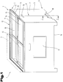
- Fig. 1 shows a schematic, perspective view of a presentation system 1.
- the presentation system 1 comprises a support system 2 and at least one transport and presentation container 3.
- the carrier system 2 is a foldable carrier ring 4 with four side walls 5 of plates, in particular web plates, with a floor and Cover region 6, 7 and formed with at least one folding region 8 and at least one stabilizing element 9.
- the support ring 4 forms the basis for the presentation system 1.
- a fixing device 10 is arranged on the stabilizing element 9. The fixing device 10 connects the stabilizing element 9 with the side wall 5 of the foldable carrier ring 4.
- the foldable carrier ring 4 serves as a substructure in the carrier system 2 on which the stabilizing element 9 is set.
- the stabilizing element 9 carries and optionally fixes the transport and presentation container 3.
- the stabilization element 9 serves on the one hand for stabilizing the carrier ring 4 in the bottom region 6 or cover region 7 or both in the bottom and in the cover region 6, 7 and / or on the other hand for holding a transport and presentation container 3.
- the stabilization takes place by means of fixing device 10 of the stabilization element 9
- the holder of a transport and presentation container 3 in Deckelbeich 7 by means of at least one projection 11 of the stabilizing element 9.
- the projection 11 may also be formed as a stack edge, which is present either circumferentially or only partially.
- the at least one projection 11 may be made in one piece with the stabilizing element 9.
- the projections 11 are separate components and are connected to the stabilizing element 9.
- the connection can be made by riveting, screwing, nailing, gluing or by other methods known from the prior art.
- the at least one projection 11 can be arranged both flush and offset on the stabilizing element 9. If a flush arrangement with the stabilizing element 9, the outwardly facing surfaces lie on a plane with the outer surfaces of the frame of the stabilizing element. 9
- the projections 11 are arranged offset inwards, in order to allow the outer surfaces of the various stabilizing elements 9 also to lie on one plane. This is advantageous for both hygienic reasons and visually.
- transport and presentation container 3 In or on these stabilizing elements 9 of the container, in particular transport and presentation container 3 is positioned, which is a reusable plastic box, a cardboard or wooden box, or a container in general, which for the presentation of goods is suitable, can be. In this transport and presentation container 3, for example, fruits and vegetables are presented.
- This mobile presentation system 1 can also be used in other areas, not just for fruit and vegetable presentations. If for the stabilizing element 9 have to be structured differently, such as another stack edge, as it is formed by the at least one projection 11, this can be done as described in the invention.
- the stabilizing element 9 itself as a container for the goods to be presented, without a transport and presentation container 3, by 9 large-area webs 13 and a full-surface contact surface are arranged between the projections 11 of the stabilizing element ,
- the stabilizing element 9 is formed as a frame 12.
- the frame 12 has to increase its own stability and also to increase the stability of the carrier ring 4 webs 13.
- the frame 12 has openings 14.
- the stabilizing element 9 may also be formed as a hollow chamber profile.
- the stabilizing element 9 can also be formed over its entire surface.
- the bottom of the stabilizing element 9 lie on a plane or at least have a recess in which objects can be placed.
- the webs 13 may have different shapes. For example, they may have a rectangular, square, L-shaped, T-shaped, C-shaped, U-shaped, V-shaped Have cross-section or the like. The webs 13 also allow the largest possible load transfer.
- the webs 13 may also be arranged at different positions of the stabilizing element 9. For example, a center bar and one side bar each can be arranged.
- the webs 13 can thus serve as a rail system for transport and presentation container 3. Especially in the storage of transport and presentation containers 3 in the openable carrier ring 4 so the transport and presentation container 3 can be pushed in and out in a simple manner.
- ribs 15 are optionally mounted, which serve for the fixation of transport and presentation containers 3, which do not extend over the entire width of the stabilizing element 9.
- transport and presentation containers 3 of the size 300 mm x 400 mm can be fixed in their position on a stabilizing frame with dimensions of 600 mm x 800 mm and do not slip even in an inclined position.
- Such ribs 15 can be arranged at arbitrary positions in the stabilizing element 9 in order to allow a fixation of the transport and presentation containers 3 in any size.
- the ribs 15 may also be designed to be movable, for example by being displaceable in an opening provided in a web 13, such as a slot.
- the mobility of the ribs 15 can also be achieved in that they are made removable from the webs 13.
- the ribs 15 in holes provided in webs 13, which are arranged at regular intervals, are inserted.
- the variability of the holder for containers of different sizes can be increased.
- the stabilizing element 9 is inserted or placed in or on the support ring 4 in order to give the support ring 4 thereby a higher stability, because a folding is prevented.
- the surface of the stabilizing element 9 corresponds substantially at least approximately or is equal to the surface of the foldable carrier ring 4 in the unfolded state, wherein in a preferred embodiment, the length and width of the carrier ring 4 on the outer circumference has a slightly smaller dimension than the length and width of the stabilizing element 9 . Because the carrier ring 4 is inserted into the U-shaped fixing device 10 of the stabilizing element 9. With an approximately same dimension, the length and width of the stabilizing element 9 are at most 0.1 cm to 10 cm, preferably 1 cm, larger than the length and width of the carrier ring 4th
- elements such as holes, recesses or elevations may be provided, which allow an arrangement of rollers 25 or feet 29 on the stabilizing element 9.
- the stabilizing element 9 can be arranged both in the cover region 7 and in the bottom region 6 of the carrier ring 4. If the stabilizing element 9 is mounted in the lid region, the projections 11 are arranged in the direction of the transport and presentation container 3 to be presented and the fixing device 10 in the direction of the carrier ring 4. If the stabilizing element 9 is mounted in the bottom region 6, however, it is rotated by 180 ° and used However, the projections 11 as a support at the bottom and the fixing device 10 is arranged in the direction of the carrier ring 4, however, in the bottom region of the carrier ring 4 and serves for fixing and stabilizing the carrier ring. 4
- a further element in the stabilizing element 9, a further element can be used, which is designed substantially tray-shaped.
- This flat tray corresponds in length and width to the dimensions within the projections 11 of the stabilizing element 9.
- This tray preferably has a peripheral edge.
- On this tray can also transport and presentation container 3 or various other items, such as. Flowers, plants, herbs, bread, baked goods, etc. will be presented.
- Fig. 1 Also shown developments of the carrier system 2.
- at least one recess 16 may be arranged in the side wall 5 of the carrier ring 4.
- This recess 16 may be arranged only on one, two, three or all four side walls of the carrier ring 4.
- the recess 16 may be formed as a handle opening or serve for attaching a handle, whereby the entire mobile presentation system 1 can be worn when needed.
- a further recess 16 may be arranged in the form of a recess in the bottom region 6 of the side wall 5 of the carrier ring 4 and thus make it possible to prevent unintentional folding of the carrier ring 4 by contact with the feet.
- the recesses 16 in the support ring 4 can also serve as openings for the escape of air, if the space is used within the support ring 4 as a storage room. In particular, when the storage space formed by the support ring 4 is cooled can escape through these openings warm air.
- additional elements 17, such as information signs or holders for product, price or advertising information can be arranged on at least one side wall 5 of the support ring 4.
- Such an additional element 17 may be, for example, a glued or screwed label holder made of plastic for price or product information.
- a locking element 18 may be arranged in the bottom area 6 of the side wall 5 of the carrier ring 4 in the folding area 8 as in Fig. 1 represented or in the lid portion 7 (not shown).
- a hook-and-loop fastener may be arranged on the inside of the carrier ring 4.
- a Velcro strip with barbs and a Velcro strip are provided with loops on each opposite side walls 5 of the support ring 4, so that the support ring 4 does not jump after folding.
- Fig. 1 shows the stabilizing element 9 straight side walls 19th
- Fig. 2 shows a schematic, perspective view of an alternative embodiment of the presentation system 1 of a support system 2 comprising the support ring 4 and the stabilizing element 9, and at least one transport and presentation container.
- the stabilizing element 9 is formed with rising side walls 19.
- the side walls 19 of the stabilizing element 9 have different side wall heights, wherein two opposing side walls 19 show a conical course and thereby at the higher end of a side wall 19 adjacent side wall 19 has a greater height than that at the lower end of a side wall 19 adjacent side wall 19 ,
- the angle of inclination can be chosen freely, but is preferably in an area where an appealing presentation of the product in the transport and presentation container 3 is possible.
- This alternative embodiment can be positioned directly on the carrier ring 4.
- the stabilizing element 9 can be set with rising side walls 19 on a stabilizing element 9 with straight side walls 19.
- the fixing device 10 of the stabilizing element 9 may be formed with rising side walls 19 by the inclined side walls 19 itself.
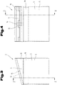
- Fig. 3 shows the side view of a support system 2 without transport and presentation container 3 with a stabilizing element 9 with inclined or oblique side walls 19.
- the stabilizing element 9 with the inclined side walls 19 is supported by the support ring 4 and interacts with the side wall 5 of the support ring 4 via the fixing device 10 In the region of the webs 13 ribs 15 are arranged.
- Fig. 4 is a front view of a carrier system 2 without transport and presentation container 3 with a stabilizing element 9 with inclined side walls 19 shown.
- the fixing device 10 connects the stabilizing element 9 with the side wall 5 of the support ring 4.
- the stabilizing element 9 is also formed as a frame 12 and has webs 13 and ribs 15.
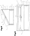
- Fig. 5 shows the sectional view BB of the stabilizing element 9 of the carrier system 2 with inclined side walls 19 Fig. 3 ,
- the fixation device 10 provides the connection to the carrier ring 4 via the interaction with the side wall 5 ago.
- the stabilizing element 9 is also formed as a frame 12 and has webs 13 and ribs 15.
- an extension 20 lying in the frame 12 is arranged on the higher side wall 19. On this extension 20 of the transport and presentation container 3 can be placed with the bottom area.
- Fig. 6 is the sectional view AA of a stabilizing element 9 with inclined side walls 19 of the carrier system 2 from Fig. 4 shown.
- the stabilizing element 9 which is formed as a frame 12, the fixing device 10 are shown in addition to the webs 13 and the ribs 15.
- the stabilizing element 9 has a C-shaped cross-section.
- Fig. 7 shows a sectional view of a locking element 18.
- the locking element 18 is U-shaped and surrounds the bottom portion 6, the support ring 4.
- the support ring 4 has for this purpose a taper 21 in the form of a notch, which engages in this area, the U-shaped locking element 18.
- the taper 21 can be achieved, for example, by compacting the material, by compressing and welding, or by weakening the material in the region to be tapered.
- the locking element 18 can be present both in the bottom and in the cover area 6,7. However, it is preferably arranged in the region of a recess 16 in the bottom region 6.
- the support ring 4 can be used in the support ring 4 (not shown). This can be pulled out again as well as the stabilizing element 9 and the support ring 4 are folded together.
- This frame if it is arranged in the bottom region 6 of the side wall 5 of the support ring 4, have a recess 16, so that the consumer does not bump against it with his feet.
- the area of the cross section of the frame substantially corresponds to the area of the cross section of the foldable carrier ring 4.
- the fixing device 10 of the stabilizing element 9 may be formed in the form of at least one extension or be formed in the simplest embodiment of the side wall 19 itself as described above, especially if a stabilizing element 9 with oblique side walls 19 on a stabilizing element 9 with straight side walls 19th is put on.
- the fixing device 10 serves for the interaction of the stabilizing element 9 with the support ring 4.
- at least one projection 11 for holding the transport and presentation container 3 may be arranged in the region of the fixing device 10.
- the projection 11 of the stabilizing element 9 may be formed, for example, as a stack edge.
- Both the fixing device 10 and the projections 11 may be arranged circumferentially or only partially. If, for example, the stabilizing element 9 is arranged in the bottom region 6, it is advantageous if the projections 11 are not formed circumferentially, so that the consumer can still place the feet comfortably under the presentation system 1.
- Both the fixation device 10 and the projections 11 may have a conical course beginning at the base of the stabilizing element 9.
- the fixing device 10 of the stabilizing element 9 may be formed as a U-shaped, C-shaped, L-shaped, T-shaped, V-shaped, etc. profile. Possible embodiments are in the 8a to 8j described.
- the projection 11 is preferably L-shaped. However, it can also have the cross sections described above. Possible embodiments of the fixing device 10 and the projection 11 in the interaction region of the stabilizing element 9 with the support ring 4 are in a simplified sectional view in the 8a to 8j shown. In each case, the side walls 5 of the carrier ring 4 and the stabilizing element 9 with the fixing device 10 and the at least one projection 11 are shown.
- a stabilizing element 9 with straight side wall 19 is shown in each case.
- a stabilizing element 9 is shown in the 8i and 8j with inclined side wall 19.
- a non-inventive stabilizing element 9 is shown in the form of a plate, wherein the interaction of the stabilizing element 9 takes place with the support ring 4 by the fixing device 10 and the extensions 20.
- the extensions 20 are in the end regions of the stabilizing element 9 is arranged.
- the holder of the transport and presentation container 3 can be made by a non-slip surface or support on the stabilizing element 9.
- Fig. 8b shows a stabilizing element 9, wherein the fixing device 10 and the projections 11 are formed equal and each projecting up and down, and thus stabilize the support ring 4 and the transport and presentation container 3 outside.
- the fixation device 10 has a straight side wall on the outside of the carrier ring 4 and an inclined side wall on the inside of the carrier ring 4.
- the projections 11 are arranged at an angle of approximately 90 ° with respect to the horizontal extent of the stabilizing element 9.
- Fig. 8d shows a stabilizing element 9, wherein the fixing device 10 is formed as a U-shaped profile and the projections 11 for holding the transport and presentation container 1 have an inclined side wall.
- Fig. 8e shows a stabilizing element 9 on a support ring 4, wherein the fixing device 10 is formed by a C-shaped profile and project the projections 11 upwards.
- Fig. 8f surrounds the stabilizing element 9 by means of fixing device 10, the support ring 4, but prevented by their formation inadvertent folding of the support ring 4.
- the transport and presentation container 3 is held by upwardly projecting projections 11.
- Fig. 8g shows a stabilizing element 9, wherein the fixing device 10 is formed step-shaped and thus the presentation height of the transport and presentation container 3 can be increased.
- Fig. 8i corresponds approximately to that in Fig. 8f ,
- the stabilizing element 9 is in Fig. 8i formed as a frame 12 with inclined side walls 19.
- Fig. 8j shows a development of the embodiment of Fig. 8i in that projections 20 for holding the transport and presentation container 3 are additionally arranged on the projections 11.
- FIGS. 8a to 8j illustrated stabilization elements 9 are configured with openings and webs 13 as a frame 12.
- FIG. 8 to 8h shown embodiments are also adapted to form stabilizing elements 9 with inclined side walls 19.
- the in the 8i and 8j shown embodiments of the projections 11 and the fixing device 10 can also be adapted for stabilizing elements 9 with straight side walls 19.
- FIGS. 8a to 8j shown embodiments of the projections 11 and the fixing device 10 can be combined with each other, whereby, for example, a circumferential U-shaped fixing device 10 as in Fig. 8d represented with an in Fig. 8f represented protrusion and the like can be connected.
- the fixing device 10 may also be designed as an area with a slip stop.
- the stabilizing element 9 can be arranged both in the bottom area and in the lid area 6, 7.
- the stabilizing element 9 serves to stabilize the carrier ring 4 or can also be used to support the carrier ring 4.
- the stabilization element serves not only to stabilize the carrier ring but also to carry at least one transport and presentation container 3. If the stabilization element 9 is arranged in the bottom region 6, it is rotated through 180 ° so that the fixation device 10 again interacts with the carrier ring 4 of the carrier system 2 , Further
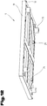
- the stabilizing element 9 with a straight side wall 19 can also be a basis for a further stabilizing element 9 with a straight or inclined side wall 19.
- Fig. 9 shows a non-inventive embodiment of the presentation system 1, wherein in the lid region 7 and in the bottom region 6 respectively different stabilizing elements 9 are arranged.
- the stabilizing elements 9 differ in that only at least one fixing element 10 and no projection 11 are arranged on the stabilizing element 9 in the base region 6.
- the same tool can be used for the production of the different stabilizing elements 9, because the recess for the production of the projections 11 in the production of the stabilizing element 9 is closed for the bottom portion 6.
- the missing projections 11 on the stabilizing element 9 in the bottom region 6 also have the advantage that a simple transport of the presentation system 1 by means of stackers is possible because projections 11 are often broken off by the fork of the truck.
- the stabilizing element 9 in the bottom region 6 is thus equal to the stabilizing element in the cover area 7 except for the missing projections 11 and it is also rotated by 180 ° on the support ring 4 is arranged.
- the arrangement is such that the fixing devices 10 interact with the stabilizing element 9 of both the lid region 7 and the bottom region 6 with the carrier ring 4.
- At least one side wall 5 of the carrier ring 4 can be designed to be openable.
- a side wall 5 may be openable at least in regions, for example to allow products such as e.g. Fruit and vegetables, other sales items, other transport or presentation containers for rapid replenishment within the support ring 4, which is designed as Faltrahmens store.
- a horizontal film hinge 22 is arranged in the middle region of a side wall 5 and the lower region of this side wall 5 is designed to be openable, in that the connection with the adjacent side walls 5 is interrupted.
- the lower part of the side wall 5 can be folded upwards, whereby in the support ring 4, a storage space is created.
- a holding element 23, such as bars, Velcro, hooks or the like arranged be.
- at least one longitudinal side wall 5 of the carrier ring 4 can be laterally slit up to half the height so that it can be folded upwards like an opening flap 24.
- This flap 24 can be provided with Velcro closures, for example, so that the opened flap 24 can be fixed in the upper region of the mobile presentation system 1 and can also be fixed in the closed state, for example on the stabilizing element 9 in the bottom region 6.
- the stabilizing element 9 in the floor area 6, which serves as a base of the mobile presentation system 1, can for this purpose have an extension in the form of a web 13, in particular a rail, as already described above, which is e.g. two transport and presentation container 3 with the bottom dimension of 600 x 400 mm in the interior of the carrier ring 4 can push.
- rollers 25, in particular rotatable rollers 25, can be arranged on the stabilization element 9 in order to achieve high mobility of the presentation system 1.
- the rollers 25 preferably have a braking function, so that the presentation system 1 is not moved unintentionally. But it can also be non-steerable rollers 25, in particular fixed castors, or a mixture of Bock and castors, be installed. In general, at least one of these rollers 25 will have a braking mechanism to protect the presentation system 1, especially on inclined planes from rolling away.
- an opening 31, in particular a hole, in the corner region of the stabilization frame 9 in the lid region 7 allows a connecting element, such as connection clip, cotter pin, etc., to be arranged in order to be able to stably connect a plurality of presentation systems 1 to a common island.
- a connecting element such as connection clip, cotter pin, etc.
- the opening 31 can also be arranged along the narrow and / or longitudinal side of the stabilizing element 9 in the frame 12 or in the stabilizing element 9 in the bottom region 6.
- FIG Fig. 10 A vertical arrangement of film hinges 22 is shown in FIG Fig. 10 represented, whereby also the interior of the carrier ring 4 is accessible.
- a film hinge is arranged on the left and right and the flaps 24 are double-winged.
- only one film hinge 22 with a flap 24 or more than two film hinges 22 may be arranged.
- a pedestal in the support ring 4 can be placed.
- a shelf or pedestal in particular display shelf 32, may be arranged in the accessible interior of the carrier ring 4.
- additional articles can be placed to optimally use the space of the presentation system 1.
- the height and width of the doors can be chosen arbitrarily.
- the display shelf 32 is placed on the stabilizing element 9, which forms the floor frame, and secured by means of feet and / or struts in the bottom frame against slipping.
- the display shelf 32 is usually made of injection-molded plastic, but can alternatively be made of cardboard or the materials already mentioned.
- the display shelf 32 has laterally each a guide rail, in which the flaps 24, which are preferably formed by card doors, engage longitudinally and thus can not be closed without external influence.
- the display shelf 32 has a rear wall, which is either fixedly connected to the shelf or, for example, connected to a hinge can be folded forward.
- This rear wall prevents goods that is placed on the display shelf 32, slide backwards and can fall into the interior of the support ring 4 of the presentation system 1. Incidentally, this also prevents the laterally latched flaps 24.
- the size of the shelf, such as width and depth, and the height of the feet or the rear wall can be arbitrarily selected as needed, if they can still be arranged in the interior of the support ring 4.
- the stabilizing element 9 in the bottom region 6 is as in Fig. 9 formed differently to the stabilizing element 9 in the lid portion 5.
- a further stabilizing element 9 with oblique side walls 19 is arranged on the stabilizing element 9 with straight side walls 19 in the lid region 5.
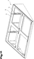
- the higher longitudinal side wall of the stabilizing element 9 with oblique side walls 19 in the lid region has at least one guide, such as insertion device 26 for information boards 27, as in Fig. 11 shown.
- the insertion device 26 can be designed both as a guide for the linkage of the panel 27 and allow as well as a stabilization of the linkage.
- two vertical guides are injected on the rear wall of the oblique stabilization element 9, into which the linkage of the product information panels 27 can be inserted.
- a breakthrough 28 is mounted to place the linkage of the panel 27 therein.
- the insertion device 26 may also be in the form of eyelets or tabs.
- the arrangement of the at least one insertion device 26 is preferably symmetrical.
- Fig. 12 is a stabilizing element 9 in the bottom portion 6, which is designed as a bottom frame, shown, which differs from a stabilizing element 9 in the lid portion 7.
- the stabilizing element 9 in the bottom region 6 is rotated by 180 ° and has no projections 11 in the direction of the bottom, but has only one fixing device 10 for the support ring 4.
- the projections 11 may also be arranged only partially, for example in the region of the short side walls 5 of the presentation system.
- the stabilizing element 9 also has openings 28 and insertion devices 26 for the attachment of panels 27. Feet 29 are also arranged on the frame 12, whereby a distancing of the stabilizing element 9 from the ground.
- the feet 29 can either be sprayed directly with the stabilizing element 9 in the bottom region 6, which forms the bottom frame, or subsequently commercially available plastic feet 29 are screwed into the stabilizing element 9 in the bottom region 6.
- the height of the feet 29 is variable, but is preferably in the range of about 100 mm, to allow for operability by means of a forklift.
- the foldable carrier ring 4 is preferably designed as a foldable web plate and thus on the one hand has a low weight and on the other hand drastically reduces the space requirement in the storage due to the foldability. Despite the low weight of the foldable carrier ring 4 but is exceptionally resilient, especially pressure and shock resistant.
- a plate of two outer layers, in particular walls, which delimit at least one core layer is understood to mean web plate.
- the core layer preferably contains webs which connect the two outer layers.
- Such web plates are also called hollow chamber plate, structural chamber plate, structured honeycomb plate.
- Web plates are sold, for example, by Friedola Tech GmbH under the name Con-Pearl Boards® or Triplex Kunststoffe GmbH. They can be made of different materials, such as plastic, cardboard, wood, etc. or a combination of two or more materials.
- the carrier ring 4 is preferably made of a plastic, such as e.g. Polypropylene, and thus has food safe properties.
- the support ring 4 is moisture resistant, which plays an important role when used as a substructure for fruit and vegetable boxes, because often dripping moisture from the boxes or the sales area are moistened to give the fruit and vegetables a pleasing appearance.
- the carrier ring 4 may also be formed from cardboard, in particular corrugated cardboard. This makes possible a very cost-effective embodiment of the carrier ring 4 or of the entire presentation system 1.
- the carrier ring 4 from a plate which contains reinforcing elements but is not necessarily designed as a web plate.
- a plate can be made of plastic and contain reinforcing elements, which are formed from the same material as the plate, for example in the form of ribs.
- the plate can also be a composite of several materials, such as a wood plastic composite or reinforcing elements of another material such as glass fibers, basalt fibers, carbon fibers, etc. included. A combination of other materials is possible.
- the plate can also be made of several layers of the same or different material.
- the stabilizing element 9 is preferably made of plastic, in particular injection-molded plastic.
- the stabilizing element 9 can also be made of other materials, such as wood, metal, composites, etc.
- At least one reinforcing element can be arranged.
- the side walls 5 of the carrier ring 4 are closed from web plates at the upper and / or lower edges, in particular welded, whereby hygiene requirements in the food sector can be met.
- a stabilizing element 9 with a straight side wall 19 serve as a basis for a further stabilizing element 9 with an inclined side wall 19. It is also possible to stack a plurality of similar stabilizing elements 9 one above the other in order to achieve the desired presentation position for the goods in a transport and presentation container 3.
- the support ring 4 has a height of almost 600 mm, which he collapsed folded into the stabilizing element 9, preferably which is designed as a floor frame, can be inserted and stored to save space.
- the support ring 4 can be adjusted in height to the appropriate presentation need.
- the stabilizing element 9 can be provided with useful additional elements, such as price strips or product information panels, both in the cover area 7 and in the floor area 6.
- useful additional elements such as price strips or product information panels, both in the cover area 7 and in the floor area 6.
- the price strip is glued to the stabilizing element 9, plugged, pushed, etc.
- connecting elements can be arranged to allow a stable connection of several presentation systems 1 to a large presentation island.
- the advantage of the mobile presentation system 1 or a mobile presentation island is also that it can be easily folded and stored in the warehouse. For this purpose, only the upper stabilizing element 9 must be pulled out of the support ring 4, if necessary, the locking element 18 are unlocked at the support ring 4 and the support ring 4 can be easily folded and removed together with the stabilizing element 9 from the presentation space and carried away.
- the carrier rings 4 In order to achieve an appealing appearance of the presentation system 1, in the arrangement of several presentation systems 1 with stabilizing elements 9 with an inclined side wall 19 to an island, the carrier rings 4 have different heights, thus achieving a large arranged in alignment display surface.
Landscapes
- Rigid Containers With Two Or More Constituent Elements (AREA)
- Engineering & Computer Science (AREA)
- Mechanical Engineering (AREA)
- Details Of Rigid Or Semi-Rigid Containers (AREA)
Claims (14)
- Système de présentation (1) comprenant un système de support (2) et le cas échéant au moins un récipient de transport et de présentation (3), plus particulièrement le cas échéant un récipient pour fruits et légumes pliable, le système de support (2) comprenant un anneau de support pliable (4) avec des parois latérales (5) en plaques, plus particulièrement en plaques-entretoises, avec une partie de fond et de couvercle (6, 7) ainsi qu'avec au moins une partie de pliage (8) et au moins un élément de stabilisation (9), l'au moins un élément de stabilisation (9) comprenant au moins un dispositif de fixation (10) grâce auquel l'élément de stabilisation (9) peut être fixé avec la paroi latérale (5) de l'anneau de support pliable (4) dans la partie de fond et/ou de couvercle (6, 7), et l'élément de stabilisation (9) du système de support (2) supportant l'au moins un récipient de transport et de présentation (3), caractérisé en ce que l'élément de stabilisation (9) est conçu comme un cadre (12), qui comprend au moins une saillie (11) pour le maintien du récipient de transport et de présentation (3), des entretoises (12) permettant d'augmenter la stabilité du cadre (12) et de l'anneau de support (4) et des passages (14).
- Système de présentation (1) selon la revendication 1, caractérisé en ce qu'une entretoise centrale et une entretoise latérale sont prévues.
- Système de présentation (1) selon la revendication 1 ou 2, caractérisé en ce que, sur les entretoises (13) de l'élément de stabilisation (9) en forme de cadre, sont réalisées des nervures (15) qui ne s'étendent pas sur toute la largeur de l'élément de stabilisation (9).
- Système de présentation (1) selon la revendication 1, caractérisé en ce que l'élément de stabilisation (9) est conçu au moins à certains endroits de manière plate, par exemple sur différents plans.
- Système de présentation (1) selon l'une des revendications 1 à 4, caractérisé en ce que, au moins dans l'angle du cadre (12), l'au moins une saillie (11) de l'élément de stabilisation (9) comprend au moins un évidement (30) et/ou au moins un passage, plus particulièrement une ouverture (31), est prévu.
- Système de présentation (1) selon l'une des revendications 1 à 5, caractérisé en ce que l'élément de stabilisation (9) comprend des parois latérales (19) qui sont inclinées ou obliques.
- Système de présentation (1) selon l'une des revendications 1 à 6, caractérisé en ce que l'au moins une paroi latérale (19) de l'élément de stabilisation (9) comprend au moins un dispositif d'enfichage (26) et l'élément de stabilisation (9) comprend, le cas échéant, dans le cadre (12), au moins un passage (28).
- Système de présentation (1) selon l'une des revendications 1 à 7, caractérisé en ce que le dispositif de fixation (10) est conçu comme un profilé en forme de U.
- Système de présentation (1) selon la revendication 8, caractérisé en ce que le profilé en forme de U est conçu de manière circulaire.
- Système de présentation (1) selon l'une des revendications 1 à 9, caractérisé en ce que les parois latérales (5) de l'anneau de support (4) sont constituées de plaques-entretoises fermées, plus particulièrement soudées au niveau des arêtes supérieures et inférieures.
- Système de présentation (1) selon l'une des revendications 1 à 10, caractérisé en ce que les parois latérales (5) de l'anneau de support (4) comprennent au moins un évidement (16).
- Système de présentation (1) selon l'une des revendications 1 à 11, caractérisé en ce qu'au moins une paroi latérale (5) de l'anneau de support (4) constituée de plaques-entretoises dans la partie de fond et/ou de couvercle (6, 7) comprend, dans la partie de pliage (8), au moins un rétrécissement (21), où au moins un élément de verrouillage (18) est disposé.
- Système de présentation (1) selon l'une des revendications 1 à 12, caractérisé en ce qu'au moins une paroi latérale (5) de l'anneau de support (4) comprend au moins à certains endroits au moins une charnière, plus particulièrement une charnière à film, et le cas échéant la liaison entre la paroi latérale (5) et la charnière à film et avec au moins une paroi latérale (5) adjacente est interrompue.
- Système de présentation (1) selon l'une des revendications 1 à 13, caractérisé en ce que plusieurs éléments de stabilisation (9) sont disposés les uns sur les autres.
Priority Applications (1)
| Application Number | Priority Date | Filing Date | Title |
|---|---|---|---|
| PL15712243T PL3099205T3 (pl) | 2014-01-31 | 2015-01-30 | System do prezentacji |
Applications Claiming Priority (3)
| Application Number | Priority Date | Filing Date | Title |
|---|---|---|---|
| AT462014 | 2014-01-31 | ||
| ATGM305/2014U AT14504U1 (de) | 2014-01-31 | 2014-08-27 | Präsentationssystem |
| PCT/AT2015/000014 WO2015113085A1 (fr) | 2014-01-31 | 2015-01-30 | Système de présentation |
Publications (2)
| Publication Number | Publication Date |
|---|---|
| EP3099205A1 EP3099205A1 (fr) | 2016-12-07 |
| EP3099205B1 true EP3099205B1 (fr) | 2019-01-02 |
Family
ID=53756028
Family Applications (1)
| Application Number | Title | Priority Date | Filing Date |
|---|---|---|---|
| EP15712243.3A Active EP3099205B1 (fr) | 2014-01-31 | 2015-01-30 | Système de présentation |
Country Status (5)
| Country | Link |
|---|---|
| EP (1) | EP3099205B1 (fr) |
| AT (1) | AT14504U1 (fr) |
| ES (1) | ES2718725T3 (fr) |
| PL (1) | PL3099205T3 (fr) |
| WO (1) | WO2015113085A1 (fr) |
Cited By (2)
| Publication number | Priority date | Publication date | Assignee | Title |
|---|---|---|---|---|
| AT523457A1 (de) * | 2020-01-31 | 2021-08-15 | Leisch Beratungs Und Beteiligungs Gmbh | Mobiles Präsentationssystem |
| WO2021217194A1 (fr) * | 2020-04-30 | 2021-11-04 | Leisch Beratungs- Und Beteiligungs-Gmbh | Système de présentation |
Families Citing this family (2)
| Publication number | Priority date | Publication date | Assignee | Title |
|---|---|---|---|---|
| AT519440A1 (de) * | 2016-12-06 | 2018-06-15 | Leisch Beratungs Und Beteiligungs Gmbh | Präsentationssystem |
| AT18583U1 (de) | 2024-10-07 | 2025-11-15 | Leisch Beratungs Und Beteiligungs Gmbh | Präsentationssystem |
Family Cites Families (11)
| Publication number | Priority date | Publication date | Assignee | Title |
|---|---|---|---|---|
| US2229257A (en) * | 1937-06-12 | 1941-01-21 | River Raisin Paper Company | Display stand |
| US2825519A (en) * | 1955-09-15 | 1958-03-04 | West Virginia Pulp & Paper Co | Display stand |
| DE2850558A1 (de) * | 1978-11-22 | 1980-06-04 | Licentia Gmbh | Transportbehaelter, insbesondere zum internen transport von bauteilen in der elektroindustrie |
| GB2113989B (en) * | 1982-01-16 | 1985-02-20 | Storviders Ltd | Display stand |
| US5230423A (en) * | 1992-05-04 | 1993-07-27 | Gellatly Georgia L | Advertising display |
| DE29707604U1 (de) * | 1997-04-21 | 1997-07-17 | Doll, Ludger, 13465 Berlin | Warenträger aus faltbarem Material |
| DE10326574B4 (de) * | 2003-06-12 | 2007-09-27 | Ifco Systems Gmbh | Transportbehältersystem und Aufsatz für ein Transportbehältersystem für Stückgut insbesondere für Obst und Gemüse |
| US6918491B2 (en) * | 2003-07-10 | 2005-07-19 | Geoffrey Alan Moss | Display stand with foldable self erecting supporting base |
| AT11858U1 (de) * | 2009-12-17 | 2011-06-15 | Leisch Beratungs Und Beteiligungs Gmbh | Untersetzvorrichtung für transport- und präsentationsbehälter |
| AT511038A1 (de) | 2011-02-09 | 2012-08-15 | Leisch Beratungs Und Beteiligungs Gmbh | Transport- und präsentationsbehälter mit schutzelement |
| US9204738B2 (en) * | 2011-10-25 | 2015-12-08 | Oren Sitton | Modular folding stand |
-
2014
- 2014-08-27 AT ATGM305/2014U patent/AT14504U1/de not_active IP Right Cessation
-
2015
- 2015-01-30 WO PCT/AT2015/000014 patent/WO2015113085A1/fr not_active Ceased
- 2015-01-30 PL PL15712243T patent/PL3099205T3/pl unknown
- 2015-01-30 EP EP15712243.3A patent/EP3099205B1/fr active Active
- 2015-01-30 ES ES15712243T patent/ES2718725T3/es active Active
Non-Patent Citations (1)
| Title |
|---|
| None * |
Cited By (3)
| Publication number | Priority date | Publication date | Assignee | Title |
|---|---|---|---|---|
| AT523457A1 (de) * | 2020-01-31 | 2021-08-15 | Leisch Beratungs Und Beteiligungs Gmbh | Mobiles Präsentationssystem |
| AT523457B1 (de) * | 2020-01-31 | 2024-04-15 | Leisch Beratungs Und Beteiligungs Gmbh | Mobiles Präsentationssystem |
| WO2021217194A1 (fr) * | 2020-04-30 | 2021-11-04 | Leisch Beratungs- Und Beteiligungs-Gmbh | Système de présentation |
Also Published As
| Publication number | Publication date |
|---|---|
| ES2718725T3 (es) | 2019-07-04 |
| PL3099205T3 (pl) | 2019-06-28 |
| AT14504U1 (de) | 2015-12-15 |
| EP3099205A1 (fr) | 2016-12-07 |
| WO2015113085A1 (fr) | 2015-08-06 |
Similar Documents
| Publication | Publication Date | Title |
|---|---|---|
| EP1261528B1 (fr) | Recipient pliant | |
| WO2015113085A1 (fr) | Système de présentation | |
| EP2512297B1 (fr) | Système de contenants de transport et de présentation | |
| EP4142547B1 (fr) | Système de présentation | |
| DE102019124657B3 (de) | Transport- und Lagerbehälter | |
| WO2016116581A1 (fr) | Contenant présentoir | |
| WO2026076478A1 (fr) | Système de présentation | |
| DE102009021684B3 (de) | Warenständer | |
| AT523457B1 (de) | Mobiles Präsentationssystem | |
| DE3704042C2 (fr) | ||
| AT17484U1 (de) | Präsentationssystem mit Regal | |
| DE19828613A1 (de) | Verkaufssystem | |
| CH709990A2 (de) | Lager- und Transportbehälter mit mindestens einem Wandelement, das eine Öffnungsvorrichtung aufweist. | |
| EP0545978B1 (fr) | Emballage en carton ondule pour transporter et presenter des marchandises a vendre avec des couvercles a surfaces de support | |
| DE202007012846U1 (de) | Faltkiste | |
| DE19505193A1 (de) | Insbesondere im Bauwesen zu verwendende Vorrichtung zum Lagern oder Transportieren von Gerätschaften oder sonstigen Teilen | |
| EP2399489B1 (fr) | Présentoir transportable | |
| DE19630821C1 (de) | Faltschachtel aus Pappe (Sockelpalette) | |
| DE20218492U1 (de) | Display mit Bodenarretierung | |
| WO2018102839A1 (fr) | Système de présentation | |
| DE9209525U1 (de) | Warenträger | |
| DE29804995U1 (de) | Transporteinheit für Stückgut | |
| DE20120563U1 (de) | Tragkorb | |
| DE202004016623U1 (de) | Ständer- und Angebotsgebinde für insbesondere Standschirme o.dgl. längliche Gegenstände | |
| CH380636A (de) | Zusammenlegbare Kiste |
Legal Events
| Date | Code | Title | Description |
|---|---|---|---|
| PUAI | Public reference made under article 153(3) epc to a published international application that has entered the european phase |
Free format text: ORIGINAL CODE: 0009012 |
|
| STAA | Information on the status of an ep patent application or granted ep patent |
Free format text: STATUS: REQUEST FOR EXAMINATION WAS MADE |
|
| 17P | Request for examination filed |
Effective date: 20160831 |
|
| AK | Designated contracting states |
Kind code of ref document: A1 Designated state(s): AL AT BE BG CH CY CZ DE DK EE ES FI FR GB GR HR HU IE IS IT LI LT LU LV MC MK MT NL NO PL PT RO RS SE SI SK SM TR |
|
| AX | Request for extension of the european patent |
Extension state: BA ME |
|
| DAX | Request for extension of the european patent (deleted) | ||
| STAA | Information on the status of an ep patent application or granted ep patent |
Free format text: STATUS: EXAMINATION IS IN PROGRESS |
|
| 17Q | First examination report despatched |
Effective date: 20170822 |
|
| GRAP | Despatch of communication of intention to grant a patent |
Free format text: ORIGINAL CODE: EPIDOSNIGR1 |
|
| STAA | Information on the status of an ep patent application or granted ep patent |
Free format text: STATUS: GRANT OF PATENT IS INTENDED |
|
| INTG | Intention to grant announced |
Effective date: 20180515 |
|
| GRAJ | Information related to disapproval of communication of intention to grant by the applicant or resumption of examination proceedings by the epo deleted |
Free format text: ORIGINAL CODE: EPIDOSDIGR1 |
|
| STAA | Information on the status of an ep patent application or granted ep patent |
Free format text: STATUS: EXAMINATION IS IN PROGRESS |
|
| INTC | Intention to grant announced (deleted) | ||
| GRAR | Information related to intention to grant a patent recorded |
Free format text: ORIGINAL CODE: EPIDOSNIGR71 |
|
| GRAS | Grant fee paid |
Free format text: ORIGINAL CODE: EPIDOSNIGR3 |
|
| STAA | Information on the status of an ep patent application or granted ep patent |
Free format text: STATUS: GRANT OF PATENT IS INTENDED |
|
| GRAA | (expected) grant |
Free format text: ORIGINAL CODE: 0009210 |
|
| STAA | Information on the status of an ep patent application or granted ep patent |
Free format text: STATUS: THE PATENT HAS BEEN GRANTED |
|
| INTG | Intention to grant announced |
Effective date: 20181122 |
|
| AK | Designated contracting states |
Kind code of ref document: B1 Designated state(s): AL AT BE BG CH CY CZ DE DK EE ES FI FR GB GR HR HU IE IS IT LI LT LU LV MC MK MT NL NO PL PT RO RS SE SI SK SM TR |
|
| REG | Reference to a national code |
Ref country code: GB Ref legal event code: FG4D Free format text: NOT ENGLISH |
|
| REG | Reference to a national code |
Ref country code: CH Ref legal event code: EP Ref country code: AT Ref legal event code: REF Ref document number: 1083333 Country of ref document: AT Kind code of ref document: T Effective date: 20190115 |
|
| REG | Reference to a national code |
Ref country code: IE Ref legal event code: FG4D Free format text: LANGUAGE OF EP DOCUMENT: GERMAN |
|
| REG | Reference to a national code |
Ref country code: DE Ref legal event code: R096 Ref document number: 502015007513 Country of ref document: DE |
|
| REG | Reference to a national code |
Ref country code: NL Ref legal event code: MP Effective date: 20190102 |
|
| REG | Reference to a national code |
Ref country code: LT Ref legal event code: MG4D |
|
| PG25 | Lapsed in a contracting state [announced via postgrant information from national office to epo] |
Ref country code: NL Free format text: LAPSE BECAUSE OF FAILURE TO SUBMIT A TRANSLATION OF THE DESCRIPTION OR TO PAY THE FEE WITHIN THE PRESCRIBED TIME-LIMIT Effective date: 20190102 |
|
| REG | Reference to a national code |
Ref country code: ES Ref legal event code: FG2A Ref document number: 2718725 Country of ref document: ES Kind code of ref document: T3 Effective date: 20190704 |
|
| PG25 | Lapsed in a contracting state [announced via postgrant information from national office to epo] |
Ref country code: NO Free format text: LAPSE BECAUSE OF FAILURE TO SUBMIT A TRANSLATION OF THE DESCRIPTION OR TO PAY THE FEE WITHIN THE PRESCRIBED TIME-LIMIT Effective date: 20190402 Ref country code: LT Free format text: LAPSE BECAUSE OF FAILURE TO SUBMIT A TRANSLATION OF THE DESCRIPTION OR TO PAY THE FEE WITHIN THE PRESCRIBED TIME-LIMIT Effective date: 20190102 Ref country code: FI Free format text: LAPSE BECAUSE OF FAILURE TO SUBMIT A TRANSLATION OF THE DESCRIPTION OR TO PAY THE FEE WITHIN THE PRESCRIBED TIME-LIMIT Effective date: 20190102 Ref country code: SE Free format text: LAPSE BECAUSE OF FAILURE TO SUBMIT A TRANSLATION OF THE DESCRIPTION OR TO PAY THE FEE WITHIN THE PRESCRIBED TIME-LIMIT Effective date: 20190102 Ref country code: PT Free format text: LAPSE BECAUSE OF FAILURE TO SUBMIT A TRANSLATION OF THE DESCRIPTION OR TO PAY THE FEE WITHIN THE PRESCRIBED TIME-LIMIT Effective date: 20190502 |
|
| PG25 | Lapsed in a contracting state [announced via postgrant information from national office to epo] |
Ref country code: RS Free format text: LAPSE BECAUSE OF FAILURE TO SUBMIT A TRANSLATION OF THE DESCRIPTION OR TO PAY THE FEE WITHIN THE PRESCRIBED TIME-LIMIT Effective date: 20190102 Ref country code: GR Free format text: LAPSE BECAUSE OF FAILURE TO SUBMIT A TRANSLATION OF THE DESCRIPTION OR TO PAY THE FEE WITHIN THE PRESCRIBED TIME-LIMIT Effective date: 20190403 Ref country code: BG Free format text: LAPSE BECAUSE OF FAILURE TO SUBMIT A TRANSLATION OF THE DESCRIPTION OR TO PAY THE FEE WITHIN THE PRESCRIBED TIME-LIMIT Effective date: 20190402 Ref country code: IS Free format text: LAPSE BECAUSE OF FAILURE TO SUBMIT A TRANSLATION OF THE DESCRIPTION OR TO PAY THE FEE WITHIN THE PRESCRIBED TIME-LIMIT Effective date: 20190502 Ref country code: LV Free format text: LAPSE BECAUSE OF FAILURE TO SUBMIT A TRANSLATION OF THE DESCRIPTION OR TO PAY THE FEE WITHIN THE PRESCRIBED TIME-LIMIT Effective date: 20190102 Ref country code: HR Free format text: LAPSE BECAUSE OF FAILURE TO SUBMIT A TRANSLATION OF THE DESCRIPTION OR TO PAY THE FEE WITHIN THE PRESCRIBED TIME-LIMIT Effective date: 20190102 |
|
| REG | Reference to a national code |
Ref country code: CH Ref legal event code: PL |
|
| PG25 | Lapsed in a contracting state [announced via postgrant information from national office to epo] |
Ref country code: LU Free format text: LAPSE BECAUSE OF NON-PAYMENT OF DUE FEES Effective date: 20190130 |
|
| REG | Reference to a national code |
Ref country code: DE Ref legal event code: R097 Ref document number: 502015007513 Country of ref document: DE |
|
| REG | Reference to a national code |
Ref country code: BE Ref legal event code: MM Effective date: 20190131 |
|
| REG | Reference to a national code |
Ref country code: IE Ref legal event code: MM4A |
|
| PG25 | Lapsed in a contracting state [announced via postgrant information from national office to epo] |
Ref country code: MC Free format text: LAPSE BECAUSE OF FAILURE TO SUBMIT A TRANSLATION OF THE DESCRIPTION OR TO PAY THE FEE WITHIN THE PRESCRIBED TIME-LIMIT Effective date: 20190102 Ref country code: DK Free format text: LAPSE BECAUSE OF FAILURE TO SUBMIT A TRANSLATION OF THE DESCRIPTION OR TO PAY THE FEE WITHIN THE PRESCRIBED TIME-LIMIT Effective date: 20190102 Ref country code: AL Free format text: LAPSE BECAUSE OF FAILURE TO SUBMIT A TRANSLATION OF THE DESCRIPTION OR TO PAY THE FEE WITHIN THE PRESCRIBED TIME-LIMIT Effective date: 20190102 Ref country code: SK Free format text: LAPSE BECAUSE OF FAILURE TO SUBMIT A TRANSLATION OF THE DESCRIPTION OR TO PAY THE FEE WITHIN THE PRESCRIBED TIME-LIMIT Effective date: 20190102 Ref country code: EE Free format text: LAPSE BECAUSE OF FAILURE TO SUBMIT A TRANSLATION OF THE DESCRIPTION OR TO PAY THE FEE WITHIN THE PRESCRIBED TIME-LIMIT Effective date: 20190102 Ref country code: RO Free format text: LAPSE BECAUSE OF FAILURE TO SUBMIT A TRANSLATION OF THE DESCRIPTION OR TO PAY THE FEE WITHIN THE PRESCRIBED TIME-LIMIT Effective date: 20190102 Ref country code: CZ Free format text: LAPSE BECAUSE OF FAILURE TO SUBMIT A TRANSLATION OF THE DESCRIPTION OR TO PAY THE FEE WITHIN THE PRESCRIBED TIME-LIMIT Effective date: 20190102 |
|
| PLBE | No opposition filed within time limit |
Free format text: ORIGINAL CODE: 0009261 |
|
| STAA | Information on the status of an ep patent application or granted ep patent |
Free format text: STATUS: NO OPPOSITION FILED WITHIN TIME LIMIT |
|
| PG25 | Lapsed in a contracting state [announced via postgrant information from national office to epo] |
Ref country code: SM Free format text: LAPSE BECAUSE OF FAILURE TO SUBMIT A TRANSLATION OF THE DESCRIPTION OR TO PAY THE FEE WITHIN THE PRESCRIBED TIME-LIMIT Effective date: 20190102 Ref country code: BE Free format text: LAPSE BECAUSE OF NON-PAYMENT OF DUE FEES Effective date: 20190131 |
|
| 26N | No opposition filed |
Effective date: 20191003 |
|
| PG25 | Lapsed in a contracting state [announced via postgrant information from national office to epo] |
Ref country code: CH Free format text: LAPSE BECAUSE OF NON-PAYMENT OF DUE FEES Effective date: 20190131 Ref country code: LI Free format text: LAPSE BECAUSE OF NON-PAYMENT OF DUE FEES Effective date: 20190131 |
|
| PG25 | Lapsed in a contracting state [announced via postgrant information from national office to epo] |
Ref country code: IE Free format text: LAPSE BECAUSE OF NON-PAYMENT OF DUE FEES Effective date: 20190130 |
|
| PG25 | Lapsed in a contracting state [announced via postgrant information from national office to epo] |
Ref country code: SI Free format text: LAPSE BECAUSE OF FAILURE TO SUBMIT A TRANSLATION OF THE DESCRIPTION OR TO PAY THE FEE WITHIN THE PRESCRIBED TIME-LIMIT Effective date: 20190102 |
|
| PG25 | Lapsed in a contracting state [announced via postgrant information from national office to epo] |
Ref country code: TR Free format text: LAPSE BECAUSE OF FAILURE TO SUBMIT A TRANSLATION OF THE DESCRIPTION OR TO PAY THE FEE WITHIN THE PRESCRIBED TIME-LIMIT Effective date: 20190102 |
|
| PG25 | Lapsed in a contracting state [announced via postgrant information from national office to epo] |
Ref country code: MT Free format text: LAPSE BECAUSE OF FAILURE TO SUBMIT A TRANSLATION OF THE DESCRIPTION OR TO PAY THE FEE WITHIN THE PRESCRIBED TIME-LIMIT Effective date: 20190102 |
|
| PG25 | Lapsed in a contracting state [announced via postgrant information from national office to epo] |
Ref country code: CY Free format text: LAPSE BECAUSE OF FAILURE TO SUBMIT A TRANSLATION OF THE DESCRIPTION OR TO PAY THE FEE WITHIN THE PRESCRIBED TIME-LIMIT Effective date: 20190102 |
|
| PG25 | Lapsed in a contracting state [announced via postgrant information from national office to epo] |
Ref country code: HU Free format text: LAPSE BECAUSE OF FAILURE TO SUBMIT A TRANSLATION OF THE DESCRIPTION OR TO PAY THE FEE WITHIN THE PRESCRIBED TIME-LIMIT; INVALID AB INITIO Effective date: 20150130 |
|
| PG25 | Lapsed in a contracting state [announced via postgrant information from national office to epo] |
Ref country code: MK Free format text: LAPSE BECAUSE OF FAILURE TO SUBMIT A TRANSLATION OF THE DESCRIPTION OR TO PAY THE FEE WITHIN THE PRESCRIBED TIME-LIMIT Effective date: 20190102 |
|
| PGFP | Annual fee paid to national office [announced via postgrant information from national office to epo] |
Ref country code: PL Payment date: 20251212 Year of fee payment: 12 |
|
| PGFP | Annual fee paid to national office [announced via postgrant information from national office to epo] |
Ref country code: GB Payment date: 20260123 Year of fee payment: 12 |
|
| PGFP | Annual fee paid to national office [announced via postgrant information from national office to epo] |
Ref country code: ES Payment date: 20260213 Year of fee payment: 12 |
|
| PGFP | Annual fee paid to national office [announced via postgrant information from national office to epo] |
Ref country code: DE Payment date: 20260116 Year of fee payment: 12 |
|
| PGFP | Annual fee paid to national office [announced via postgrant information from national office to epo] |
Ref country code: AT Payment date: 20260123 Year of fee payment: 12 |
|
| PGFP | Annual fee paid to national office [announced via postgrant information from national office to epo] |
Ref country code: IT Payment date: 20260123 Year of fee payment: 12 |
|
| PGFP | Annual fee paid to national office [announced via postgrant information from national office to epo] |
Ref country code: FR Payment date: 20260126 Year of fee payment: 12 |