EP3099360B1 - Inhalateur de poudre et set pour l'inhalation de poudre - Google Patents
Inhalateur de poudre et set pour l'inhalation de poudre Download PDFInfo
- Publication number
- EP3099360B1 EP3099360B1 EP15705188.9A EP15705188A EP3099360B1 EP 3099360 B1 EP3099360 B1 EP 3099360B1 EP 15705188 A EP15705188 A EP 15705188A EP 3099360 B1 EP3099360 B1 EP 3099360B1
- Authority
- EP
- European Patent Office
- Prior art keywords
- powder
- powder inhaler
- depression
- inhaler
- half shells
- Prior art date
- Legal status (The legal status is an assumption and is not a legal conclusion. Google has not performed a legal analysis and makes no representation as to the accuracy of the status listed.)
- Active
Links
Images

Classifications
-
- A—HUMAN NECESSITIES
- A61—MEDICAL OR VETERINARY SCIENCE; HYGIENE
- A61M—DEVICES FOR INTRODUCING MEDIA INTO, OR ONTO, THE BODY; DEVICES FOR TRANSDUCING BODY MEDIA OR FOR TAKING MEDIA FROM THE BODY; DEVICES FOR PRODUCING OR ENDING SLEEP OR STUPOR
- A61M15/00—Inhalators
- A61M15/0028—Inhalators using prepacked dosages, one for each application, e.g. capsules to be perforated or broken-up
- A61M15/003—Inhalators using prepacked dosages, one for each application, e.g. capsules to be perforated or broken-up using capsules, e.g. to be perforated or broken-up
- A61M15/0033—Details of the piercing or cutting means
- A61M15/0041—Details of the piercing or cutting means with movable piercing or cutting means
-
- A—HUMAN NECESSITIES
- A61—MEDICAL OR VETERINARY SCIENCE; HYGIENE
- A61M—DEVICES FOR INTRODUCING MEDIA INTO, OR ONTO, THE BODY; DEVICES FOR TRANSDUCING BODY MEDIA OR FOR TAKING MEDIA FROM THE BODY; DEVICES FOR PRODUCING OR ENDING SLEEP OR STUPOR
- A61M11/00—Sprayers or atomisers specially adapted for therapeutic purposes
- A61M11/001—Particle size control
- A61M11/002—Particle size control by flow deviation causing inertial separation of transported particles
-
- A—HUMAN NECESSITIES
- A61—MEDICAL OR VETERINARY SCIENCE; HYGIENE
- A61M—DEVICES FOR INTRODUCING MEDIA INTO, OR ONTO, THE BODY; DEVICES FOR TRANSDUCING BODY MEDIA OR FOR TAKING MEDIA FROM THE BODY; DEVICES FOR PRODUCING OR ENDING SLEEP OR STUPOR
- A61M15/00—Inhalators
- A61M15/0001—Details of inhalators; Constructional features thereof
- A61M15/0003—Details of inhalators; Constructional features thereof with means for dispensing more than one drug
-
- A—HUMAN NECESSITIES
- A61—MEDICAL OR VETERINARY SCIENCE; HYGIENE
- A61M—DEVICES FOR INTRODUCING MEDIA INTO, OR ONTO, THE BODY; DEVICES FOR TRANSDUCING BODY MEDIA OR FOR TAKING MEDIA FROM THE BODY; DEVICES FOR PRODUCING OR ENDING SLEEP OR STUPOR
- A61M15/00—Inhalators
- A61M15/0001—Details of inhalators; Constructional features thereof
- A61M15/0005—Details of inhalators; Constructional features thereof with means for agitating the medicament
-
- A—HUMAN NECESSITIES
- A61—MEDICAL OR VETERINARY SCIENCE; HYGIENE
- A61M—DEVICES FOR INTRODUCING MEDIA INTO, OR ONTO, THE BODY; DEVICES FOR TRANSDUCING BODY MEDIA OR FOR TAKING MEDIA FROM THE BODY; DEVICES FOR PRODUCING OR ENDING SLEEP OR STUPOR
- A61M15/00—Inhalators
- A61M15/0001—Details of inhalators; Constructional features thereof
- A61M15/0021—Mouthpieces therefor
-
- A—HUMAN NECESSITIES
- A61—MEDICAL OR VETERINARY SCIENCE; HYGIENE
- A61M—DEVICES FOR INTRODUCING MEDIA INTO, OR ONTO, THE BODY; DEVICES FOR TRANSDUCING BODY MEDIA OR FOR TAKING MEDIA FROM THE BODY; DEVICES FOR PRODUCING OR ENDING SLEEP OR STUPOR
- A61M15/00—Inhalators
- A61M15/0028—Inhalators using prepacked dosages, one for each application, e.g. capsules to be perforated or broken-up
-
- A—HUMAN NECESSITIES
- A61—MEDICAL OR VETERINARY SCIENCE; HYGIENE
- A61M—DEVICES FOR INTRODUCING MEDIA INTO, OR ONTO, THE BODY; DEVICES FOR TRANSDUCING BODY MEDIA OR FOR TAKING MEDIA FROM THE BODY; DEVICES FOR PRODUCING OR ENDING SLEEP OR STUPOR
- A61M15/00—Inhalators
- A61M15/0028—Inhalators using prepacked dosages, one for each application, e.g. capsules to be perforated or broken-up
- A61M15/0045—Inhalators using prepacked dosages, one for each application, e.g. capsules to be perforated or broken-up using multiple prepacked dosages on a same carrier, e.g. blisters
- A61M15/0046—Inhalators using prepacked dosages, one for each application, e.g. capsules to be perforated or broken-up using multiple prepacked dosages on a same carrier, e.g. blisters characterized by the type of carrier
- A61M15/0051—Inhalators using prepacked dosages, one for each application, e.g. capsules to be perforated or broken-up using multiple prepacked dosages on a same carrier, e.g. blisters characterized by the type of carrier the dosages being arranged on a tape, e.g. strips
-
- A—HUMAN NECESSITIES
- A61—MEDICAL OR VETERINARY SCIENCE; HYGIENE
- A61M—DEVICES FOR INTRODUCING MEDIA INTO, OR ONTO, THE BODY; DEVICES FOR TRANSDUCING BODY MEDIA OR FOR TAKING MEDIA FROM THE BODY; DEVICES FOR PRODUCING OR ENDING SLEEP OR STUPOR
- A61M15/00—Inhalators
- A61M15/08—Inhaling devices inserted into the nose
-
- A—HUMAN NECESSITIES
- A61—MEDICAL OR VETERINARY SCIENCE; HYGIENE
- A61M—DEVICES FOR INTRODUCING MEDIA INTO, OR ONTO, THE BODY; DEVICES FOR TRANSDUCING BODY MEDIA OR FOR TAKING MEDIA FROM THE BODY; DEVICES FOR PRODUCING OR ENDING SLEEP OR STUPOR
- A61M15/00—Inhalators
- A61M15/0028—Inhalators using prepacked dosages, one for each application, e.g. capsules to be perforated or broken-up
- A61M15/003—Inhalators using prepacked dosages, one for each application, e.g. capsules to be perforated or broken-up using capsules, e.g. to be perforated or broken-up
- A61M15/0043—Non-destructive separation of the package, e.g. peeling
-
- A—HUMAN NECESSITIES
- A61—MEDICAL OR VETERINARY SCIENCE; HYGIENE
- A61M—DEVICES FOR INTRODUCING MEDIA INTO, OR ONTO, THE BODY; DEVICES FOR TRANSDUCING BODY MEDIA OR FOR TAKING MEDIA FROM THE BODY; DEVICES FOR PRODUCING OR ENDING SLEEP OR STUPOR
- A61M15/00—Inhalators
- A61M15/0028—Inhalators using prepacked dosages, one for each application, e.g. capsules to be perforated or broken-up
- A61M15/0063—Storages for pre-packed dosages
-
- A—HUMAN NECESSITIES
- A61—MEDICAL OR VETERINARY SCIENCE; HYGIENE
- A61M—DEVICES FOR INTRODUCING MEDIA INTO, OR ONTO, THE BODY; DEVICES FOR TRANSDUCING BODY MEDIA OR FOR TAKING MEDIA FROM THE BODY; DEVICES FOR PRODUCING OR ENDING SLEEP OR STUPOR
- A61M2202/00—Special media to be introduced, removed or treated
- A61M2202/06—Solids
- A61M2202/064—Powder
-
- A—HUMAN NECESSITIES
- A61—MEDICAL OR VETERINARY SCIENCE; HYGIENE
- A61M—DEVICES FOR INTRODUCING MEDIA INTO, OR ONTO, THE BODY; DEVICES FOR TRANSDUCING BODY MEDIA OR FOR TAKING MEDIA FROM THE BODY; DEVICES FOR PRODUCING OR ENDING SLEEP OR STUPOR
- A61M2205/00—General characteristics of the apparatus
- A61M2205/58—Means for facilitating use, e.g. by people with impaired vision
- A61M2205/586—Ergonomic details therefor, e.g. specific ergonomics for left or right-handed users
-
- A—HUMAN NECESSITIES
- A61—MEDICAL OR VETERINARY SCIENCE; HYGIENE
- A61M—DEVICES FOR INTRODUCING MEDIA INTO, OR ONTO, THE BODY; DEVICES FOR TRANSDUCING BODY MEDIA OR FOR TAKING MEDIA FROM THE BODY; DEVICES FOR PRODUCING OR ENDING SLEEP OR STUPOR
- A61M2206/00—Characteristics of a physical parameter; associated device therefor
- A61M2206/10—Flow characteristics
- A61M2206/14—Static flow deviators in tubes disturbing laminar flow in tubes, e.g. archimedes screws
-
- A—HUMAN NECESSITIES
- A61—MEDICAL OR VETERINARY SCIENCE; HYGIENE
- A61M—DEVICES FOR INTRODUCING MEDIA INTO, OR ONTO, THE BODY; DEVICES FOR TRANSDUCING BODY MEDIA OR FOR TAKING MEDIA FROM THE BODY; DEVICES FOR PRODUCING OR ENDING SLEEP OR STUPOR
- A61M2206/00—Characteristics of a physical parameter; associated device therefor
- A61M2206/10—Flow characteristics
- A61M2206/16—Rotating swirling helical flow, e.g. by tangential inflows
-
- A—HUMAN NECESSITIES
- A61—MEDICAL OR VETERINARY SCIENCE; HYGIENE
- A61M—DEVICES FOR INTRODUCING MEDIA INTO, OR ONTO, THE BODY; DEVICES FOR TRANSDUCING BODY MEDIA OR FOR TAKING MEDIA FROM THE BODY; DEVICES FOR PRODUCING OR ENDING SLEEP OR STUPOR
- A61M2207/00—Methods of manufacture, assembly or production
Definitions
- the invention relates to a powder inhaler and a powder inhalation set of powder inhaler and blister element.
- Powder inhalers for sublingual, nasal and inhalative administration of powdered, solid pharmaceuticals or other means are known. They can be designed as propellant-free application devices and release an aerosol through the inspiratory process, respectively a deep inhalation process. The energy for the dispersion is gained through the inspiratory flow.
- the powdery substance is contained in a storage container; Special storage containers such as blisters are also known.
- the pure active ingredient or the active ingredient is used with a carrier which is a safe excipient such as lactose or glucose for adhered drug particles.
- Known powder applicators or powder inhalers may, depending on the configuration, administer up to three different types of powders.
- a powder inhaler describes the EP 1 769 818 B1 :
- a propellant-free powder inhaler is used for the inhalative application of powdered solid pharmaceuticals, which also allows inhalation of a powder combination. This is achieved in that the powder inhaler has at least two storage containers in which different powders are stored separately in a plurality of metering units. The powders can be combined appropriately and administered via a common inhalation tube.
- the powder inhaler DE 10 2005 046 645 B3 which also has at least two storage containers for the different powders and makes it possible for these to be metered separately from one another in a metering device and then mixed together during inhalation.
- the administration of different powders can also take place as a single dose.
- the powder inhaler of the DE 10 2005 046 644 B3 in the supply air duct a helical or spiral swirling means to fluidize the air prior to feeding to the powder for finer distribution of the powder in the air stream.
- a single dose inhaler is from the DE 20 2011 103503 U1 known.
- the powder inhaler for capsules described therein comprises a blade housing and a mouthpiece housing, as well as a capsule carrier and a plurality of blades.
- the entire inhalation process should be able to be activated by only one sliding movement, for this purpose, the device has only two mutually movable housing parts, by their displacement to each other first closed the insertion opening for the capsule and thereby the capsule is held back in a bore in the inhaler. Inside the inhaler, the capsule is then opened with suitably shaped metallic blades.
- Out EP 2 015 812 B1 is a powder inhaler for the simultaneous administration of several drugs known to be present in a single dose blister strip in different wells.
- a mouthpiece of the powder inhaler is movably attached to a strip support.
- corresponding recesses for receiving the blister cavities are formed.
- a cover sheet of the inserted blister can be peeled off with the mouthpiece closed by the cover sheet having a folded-over overlap protruding from the closed powder inhaler.
- WO 2011/154371 A1 discloses a powder inhaler of very complex construction consisting of a plurality of parts.
- a plurality of air inlet openings are provided in the lid, which closes a curved air flow channel.
- the air inlet openings extend over the air flow channel, which has a direct channel section, which leads directly to the vortex chamber, and has a container channel portion which passes through the receiving trough in which a blister is received with its active substance well.
- a rib pointing away from the cover in the direction of the receptacle provides for a deflection of the airflow channel into the active agent well.
- WO 2013/036881 A2 a three-part powder inhaler is described, in which the powder air outlet area towards the mouthpiece is a separate component.
- a torsion chamber is formed, open into the air inlet ducts, which are formed in a third component, after joining of the components.
- the third component also has an outlet grille opening which comes to lie on the torsion chamber and to which the separate outlet piece is fastened.
- This inhaler is intended for single use, the components are glued together, an opening of the powder inhaler after use is not provided.
- the out WO 2014/006135 A2 known Pulverinhalator consists of hingedly interconnected via a film hinge shells, which have in the assembled arrangement an air inlet area with a 180 ° turn of the air flow in front of the powder receiving trough and a grid in the outlet area for deagglomeration.
- a powder inhaler for a powder packed in a blister is known.
- the powder inhaler consists of two housing parts, which are assembled in a predetermined mutual position in an activated state.
- the housing thereby forms an open at an inflow end and at an outflow end air flow channel and has a device for receiving the blister cavity with the pharmaceutical powder and a device for opening the blister, which is activated upon assembly of the housing parts.
- the one housing part, in which the device for receiving the blister tray is formed, is an elongate, flat base.
- the second housing part with the device for opening the blister tray is an elongated, flat top, wherein the device for opening the blister tray is formed as a projection with which the cover sheet of the blister is pierced during assembly of the housing parts.
- At least one housing part has at its longitudinal edges projecting strips which limit the air flow channel at its longitudinal sides in the assembled state of the housing parts in cooperation with the other housing part.
- GB 2 270 293 A describes a Pulverinhalator of two half-shells, of which the upper half-shell with membranes sealed holes, in each of which there is a powder dose.
- the membrane is opened by pressing in a cap with a cutting edge so that the powder enters the powder release area.
- the inhaler has tortuous supply air ducts which extend from the air inlet openings to the powder release area and provide air swirling.
- the in GB 2460281 described inhaler consists of several layers laminated together so that it has the size of a credit card.
- the middle layer has cutouts for the air inlet area, a tapered air passage, the drug chambers and the air outlet area.
- In the cover layer there are an air inlet that overlies the air inlet portion of the middle layer and vents that overlie each drug chamber.
- Between the middle and the bottom layer may be provided a further layer with a recess under the air passage in the middle layer. This recess, in which the drug is present, is sealed by a folded foil strip which protrudes through the air inlet and can be withdrawn to open the recess.
- a powder inhaler comprises two half shells, which are hinged together or can be connected. Surround the two half shells in an assembled arrangement, an air inlet region, a powder deposition and release region, and an outlet region through which a fluid path passes. In the air inlet region, at least one of the half shells has one or more air inlet openings. Further, in the air inlet region there is at least one air swirling structure defining the fluid path between the air inlet port (s) and the powder deposition and release region in which one of the two half shells has at least one powder receiving well.
- the air swirling structure swirls the air in the air inlet area, so that the powder is discharged completely out of the powder receiving recess and already at least partially deagglomerated by the swirling air flow supplied into the powder deposition and release area.
- Both half-shells are formed in the outlet region, which has at least one deagglomeration structure to an outlet.
- the two half-shells in the assembled state so to speak, form a flow housing for the fluid path between the air inlet openings and the outlet, so that the aerosol, which, when inhaled in the powder deposition and release area, is to be inhaled powder which is provided in the powder receiving trough. and breathing air is formed, can be inhaled through the outlet by the user.
- the outlet of the powder inhaler may be formed as a mouthpiece, such as a beak, or for inhalation through the nose as a nosepiece, such as a curved nose tube.
- the half-shells of the powder inhaler can be advantageously produced as injection-molded components, which makes the production particularly cost-effective.
- the articulated connection of the half-shells allows the powder inhaler to be easily opened and closed, which facilitates keeping the powder inhaler clean for multiple use.
- the hinges support the correct assembly of the half-shells by the user.
- this is formed according to the invention from two flat half shells with an elongated, substantially rectangular, trapezoidal, teardrop-shaped or oval base.
- the shell results because the rectangular or other shaped base is bounded by a wall or wall sections.
- the elongated half-shells therefore have a longitudinal axis, at both ends of which on the one hand Air inlet openings and on the other the outlet are provided.
- the air inlet openings are arranged on a side facing away from the outlet side wall portion of one or both half-shells;
- it is the half-shell, which does not carry the powder receiving trough. This is due to the fact that with the overall design of the formed for an optimal flow path fluid path is to be formed.
- fluid path here means the way the air initially travels alone and after carrying the powder through the air travels the aerosol.
- the aerosol is formed when the present in the trough, portioned powdery active substance is taken by inhaled air and sufficiently mixed and atomized on the subsequent Diffusorumble.
- at least one of the half shells, but preferably both, has at least two guide webs extending from the wall section at which the air inlet openings are present connect the wall section with the air inlet openings, extending to the powder receptacle.
- the guide webs of a half-shell with respect to their height to the other half-shell or - if both half-shells have guide webs - up to the guide webs of the other half-shell, so that two adjacently adjacent guide webs form a supply air duct, which has a tapered cross section to the powder receiving trough , and limit the fluid path in the air inlet area.
- the air is compressed in a funnel shape by the cross-sectional taper and is twisted by the air swirling structure disposed in the air passage forming flow obstacles to the air flow passing along the fluid path so that the airflow generated by inhalation has the highest speed and turbulence at the "funnel tip" when he reaches the powder receiving trough.
- This is according to the invention enclosed on both sides by guide walls which extend from the outermost longitudinal webs guide the air flow from the air inlet area through the powder receiving trough. As a result, the powder is completely taken out of the powder receiving trough. An optimal flow path is thus ensured regardless of the type and depth of inspiration of the user.
- the half shell In order to release an active ingredient contained in a well of a blister element, when the blister element is received with the well in the powder receiving well of the powder inhaler, in the powder deposition and release region, the half shell, does not have the powder receiving trough (s), a punch at a corresponding opposite location on.
- This stamp is inserted by means of an elastic insert in this half-shell in the direction of at least one powder receiving trough movable and formed as a mandrel for opening a drug trough of the inserted blister element.
- the punch can be moved by pressure from outside at the location of the elastic insert in the direction of the powder receiving trough (s) for piercing the blister foil, and returns to its original position upon release of the external pressure due to the restoring force of the elastic insert.
- a recess is provided on one of the half shells on a side wall section at the level of the powder receiving trough whose width and height correspond to the width and height of a blister element which is predetermined for insertion into this powder inhaler.
- the powder inhaler per se can be designed to serve to receive certain blister elements.
- the powder inhaler has at least one of the above-described features of the mandrel and the recess.
- the recess may have a height which is higher than the height of the blister element. Height refers to the height of the carrier foil and not to the height of the medicament tray.
- the second half-shell which does not have the recess, has a projection on the side wall portion, which comes to lie over the recess in an assembled arrangement of the half-shells. This is designed to close the recess when a corresponding blister element is received in the powder inhaler, d. H. that the blister film protrudes through the recess from the inhaler, and the supernatant rests against the blister foil.
- the recess may be provided so that the inhaler is designed for right-handed or left-handed people.
- Closing the recess after inserting the blister element prevents air from being drawn into the inhaler at an undesired point during inhalation.
- the guide webs are arranged such that at least one supply air channel leads to each of the powder receiving wells.
- an air swirling structure according to the invention can be formed by a plurality of transverse webs extending between adjacent guide webs, wherein the transverse webs in both half-shells are arranged in such a way that they run in opposite directions in the assembled arrangement, i. H. do not come over each other, but cross each other.
- the fluid path from the air inlets runs alternately in both half shells to the powder receiving trough and is thus set in torsion and turbulence.
- the articulated connection of the two half-shells can be provided for example by a hinge on adjacent side walls or by a pivot joint.
- the hinge By means of the hinge, the half shells can be pivoted in a folding movement for opening and closing about a longitudinal axis present on the edge, while the pivot joint, which may preferably be arranged in the region between a side wall and the wall section remote from the outlet side, rotates the two half shells against each other.
- the embodiment with hinge allows elements inside the powder inhaler such.
- the disagglomerating structures may protrude beyond the dividing plane of the respective half-shell as long as they are received in the second half-shell. If a swivel joint is used, then it must be ensured that the respective structures do not protrude beyond the wall of the half shell.
- the deagglomeration structure or any deagglomeration structure in the outlet region can be formed by a group of profile elements arranged annularly around a cylinder, wherein both cylinders and the profile elements of each deagglomeration structure extend between the two half-shells.
- the deagglomeration structure (s) can be arranged on one of the two half-shells or, if there is more than one deagglomeration structure, distributed on both half-shells at different locations in the outlet region.
- the disagglomeration structure (s) is / are formed by two half-structures that do not protrude above the dividing plane of the half-shells, and one half-structure is arranged on each half-shell, so that the half-structures in the assembled arrangement of the half-shells constitute the deagglomeration structure form.
- the disagglomeration structures serve as flow obstacles to the fact that when transporting the powder and entrainment by the air flow possibly larger powder particles are smashed by the flow obstacles and thus reduced. Furthermore, this may optionally be the active ingredient separated from a carrier.
- disagglomerators can be positioned as disagglomerators further, arbitrarily shaped mechanical resistances, respectively flow resistances, to form the fluid path adapted to the needs and the specification of the drug.
- mechanical resistances respectively flow resistances
- In question come here, for example, also webs, wing or wall-shaped and bollard-shaped structures.
- the overall design of the fluid path serves to provide optimal flow and acceleration of the inspired airflow and improved entrainment and atomization of the powdered drug. It should be achieved in particular that the powder receiving trough is completely emptied of the powder therein with a breath.
- the inhaler according to the invention is particularly hygienic to handle by its design and by the ability to unfold and clean it. He is without blades, Springs or lever formed.
- the adhesion and the friction in the inhaler play an important role; Adhesion and friction between the drug and the inhaler can be overcome by the fluid path guide to prevent the powder particles from adhering to the inhaler inner surface.
- the airflow and exhaust flow obstructions are designed to optimize airflow velocity and turbulence to achieve the best possible powder release and deagglomeration, resulting in improved inhalation performance.
- the half-shell which has the powder-receiving trough, can have at least one stop element, which serves for the bordering of a predetermined blister element for receiving into the powder inhaler.
- the blister element when it is inserted, can not slip.
- both half shells at the side wall sections at the level of the powder receiving trough opposite the recess and opposite the supernatant can have a corrugation whose width corresponds to the width of a blister element predetermined for insertion into the powder inhaler, so that this is held between the corrugated wall portions in the assembled arrangement of the powder inhaler.
- the half-shell which has the powder receptacle, a supernatant, such as a dome-shaped projection, which is adapted to be brought into engagement with a corresponding recess of the blister element, which is intended, in a powder inhaler according to the invention to be inserted.
- a supernatant such as a dome-shaped projection
- the supernatant or the corrugation serves as an abutment when removing the lid film on the projecting from the closed powder inhaler overlap, so that the active substance well of the blister element safely remains in the powder receiving trough.
- At least one of the two shells may be made of transparent plastic in the area of the powder receiving trough to allow it to be seen in the powder receiving trough and thus to visually check that the powder has been completely discharged from the powder receiving trough after an inhalation process is completed.
- locking means are provided for joining suitable manner; the formation of such locking means is known in the art.
- the locking means may be provided on the corresponding edges of the half-shells.
- both half shells possibly also articulated helical insertable Heilverwirbelungs Modell, via locking means, so that these elements can be easily locked together by coupling and coupled.
- a Pulverinhalathsset which consists of the powder inhaler according to the invention on the one hand and on the other hand from a corresponding blister element which is dimensioned for inclusion in the powder inhaler.
- a blister element has a carrier plate or foil with a trough in which the powder is received, respectively, the inhalable active ingredient.
- a suitable blister element can also have two or more wells with different active ingredient powders to be inhaled at the same time.
- the blister element further has a cover plate or foil which closes the well (s) as long as the powder is to be stored in the blister.
- the trough (s) of the blister element is / are sized and positioned to be received in the powder receiving trough (s) of the powder inhaler.
- the cover plate can be detached from the carrier plate and thus from the active agent well by forming the cover plate, for example with a foldable overlap, when the blister element is inserted into the powder inhaler protrudes through the recess in a side wall portion at the level of the powder receiving trough from the powder inhaler and can be deducted.
- An alternative embodiment provides a simpler blister element that does not need to protrude from the powder inhaler with a portion of the top panel, but merely accurately inserted with the active substance well into the powder receiving trough of the powder inhaler.
- a capsule-like blister element or a specially designed capsule can be used.
- the opening of the active ingredient well is not done by peeling off the cover plate but by perforation of the same.
- a designed according to the invention powder inhaler is formed with an elastically movable and designed as a mandrel stamp against the powder receiving trough.
- a powder inhaler according to the invention is equipped with both opening mechanisms, so that both blister types can be opened.
- the device according to the invention relates to a powder inhaler for inhalation administration through the mouth or nose of a stored in a blister powdered drug, which may be a drug, but also an active ingredient, which is not necessarily defined as a drug, and which is inhaled by a person ,
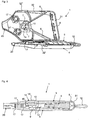
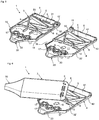
- Fig. 1 1 shows two half-shells 3, 4 of a powder inhaler 1 according to the invention for inhalation application, wherein the half-shells 3 and 4 are articulated by means of a hinge 15 ", one of the half-shells, in the present case the lower half-shell 4 is connected via a film hinge 16 to a helical air swirling structure 5, which consists of an elliptical frusto-conical base body 51 around which an elevation 52 winds, so that the air flow must follow from the inlet openings 8 of the coil 52 and is thereby put into turbulence and rotation After folding the air vortex structure 5 into the space between the guide webs 6 (cf. Fig.
- the blister element 100 is inserted at a location provided for this purpose (cf. Fig. 2 ). After folding the Heilverwirbelungs Modell 5 and folding the two half-shells 3 and 4 (see. Fig. 4 ) the powder inhaler 1 is ready for use, it is only necessary to open the medicament trough 101 of the blister element 100.
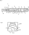
- FIGS. 5 to 8 show a further powder inhaler 1 according to the invention with an alternative air swirling structure 5 and a rotary joint 15, 15 'as an articulated connection of the two half shells 3 and 4.
- the air swirling structure 5 is formed by traversal webs 53 which lie in a zigzag line between the guide webs 6 of each half shell 3, 4 run, so that the Travers webs 53 in the assembled arrangement of the half-shells 3.4 cross each other (see. Fig. 8 ) and so the air flow from the air inlet openings 8 alternately into the lower half shell 4 and the upper half shell 3 lead with each change of direction, so that here turbulence are generated.
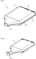
- Fig. 9 shows a powder inhaler 1 in a folded arrangement, in which the outlet as in Fig. 1 to 8 is formed as a mouthpiece 20.
- the outlet as in Fig. 1 to 8 is formed as a mouthpiece 20.
- the inventive design of the three subregions ensures that an application of the active ingredient, also referred to herein as a drug, upon inhalation optimal air flow is formed, regardless of the way in which the patient inhales. In this way, the drug can be inhaled optimally and thus show the best possible effect.
- a drug also referred to herein as a drug
- the air supply area is formed in the examples shown in the figures by the powder receiving trough 9 towards tapered, bounded by the guide webs 6 supply air into which flows through the air inlets 8 air when the patient inhales with the mouthpiece 20 received in the mouth.
- the air inlets 8 are formed in the rear wall 31 of the half-shell 3 and at the contact surface of the rear walls 31,41 between the two half-shells 3,4 (see. Fig. 5 ).
- the tapering supply air duct and the respective air swirling structure 5 present therein provide for turbulence and increase the speed of the supply air flow before entry into the powder receiving recess 9.
- the number of Zu povertykanäle and arranged therein Heilverwirungsungstechniks Designen in other embodiments, in particular also in embodiments with more than one powder receiving trough, be varied by a corresponding increase in the number of guide ribs.
- the half-shell 4 has a recess 32 'in a side wall 42, through which the inserted blister 100 extends with a folded-over overlap 102 of the cover film of the blister element 100.
- This recess 32 ' is sealed airtight by the projection 32 "on the other half-shell 3.
- the active substance depression 101 of the blister element 100 which could also be termed a capsule, is accommodated in the recess 9 formed in the half-shell 4.
- the stops 12 are also provided in the half-shell 4.
- guide walls 7 (shown in FIG. Fig. 1 . Fig. 7 ) , which extend from the longitudinal webs 6 and guide the air flow from the air inlet region through the powder receiving trough 9 and the therein arranged, open, powder-filled trough 101 of the blister element 100.
- the blister chamber 11 is adjoined by the outlet region, through which the now formed aerosol of air and medicament powder is discharged.
- the bladder chamber 11 is delimited in the outlet area by the deagglomeration structures 17, 17 'through which the air stream now laden with active substance does not pass directly to the outlet, but turbulences are generated by the further deflection in order to prevent sedimentation or agglomeration of the powder medicament.
- First provides the cross-sectional widening after passing through the guide walls 7 narrow passage through the powder receiving trough 9 for a reduction of the flow velocity and thus achieves a spacer effect, ie the active ingredient particles are evenly distributed in the air stream.
- the deagglomeration of the active ingredient particles is subsequently assisted by the outlet end with mouthpiece 20 which is tapered in the disagglomerating structures 17, 17 'in the outlet section tapering through the wall sections 22.
- the powder inhalers 1 each have three deagglomeration structures 17, 17 ', wherein in the exemplary embodiment in FIG Fig. 1 to 4 a deagglomeration structure 17 are arranged in the lower half-shell 4 and two deagglomeration structures 17 are arranged in the upper half-shell 3.
- a deagglomeration structure 17 are arranged in the lower half-shell 4 and two deagglomeration structures 17 are arranged in the upper half-shell 3.
- the or each deagglomeration structure 17, 17 'in the outlet region can be defined by a group of profile elements arranged annularly around a cylinder, e.g. B. fins are formed. These fins may have an airfoil-like profile in order to swirl the air flow defined.
- the three deagglomeration structures are each formed by two half-structures 17 'in each of the half-shells 3,4.
- the half-structures 17 ' extend only to the dividing plane defined by the half-shells 3, 4, so that they can be pivoted about the rotary joint 15 and recess 15'.
- care must be taken in this embodiment that none of the elements and structures in the interior of the half shells 3, 4 protrude beyond the dividing plane, as do the guide walls 7 and the crossbars 53.
- the side wall 32 faces the half shell 3 here as well the recess 32 'on the side wall 42 of the half-shell 4 no projection on; the recess 32 'is therefore designed with a smaller depth, so that the half-shells 3.4 seal tightly with inserted blister element at this point. Only the portion of the side wall 32 or half shell 3 with the corrugation 18 protrudes beyond the dividing plane and the corresponding section with the corrugation 18 on the side wall 42 of the lower half shell 4 is lowered accordingly.
- a pivoting of the upper half-shell 3 is connected for opening in a clockwise direction and for closing in a counterclockwise direction. If the corrugated projection were on the lower half shell and a correspondingly lowered corrugated portion on the upper half shell, the Verschwenkungscardien would be exactly the opposite for opening and closing. In order to facilitate the user the correct handling, appropriate information, such as arrow marks on the outside of the half-shells can be provided.
- An inventive powder inhaler 1 of two half-shells 3 and 4 can advantageously be prepared quickly and inexpensively by injection molding of a plastic. All necessary structures are present in the half-shells or in the case of the frustoconical screw are integrally connected to one of the half-shells. The assembly of the half-shells on the longitudinal hinge or the swivel joint is inexpensive, there are no further items required.
- the powder inhaler 1 can be converted from the two half-shells 3, 4 into a ready-for-use state after inserting a blister element 100 during the opened state and by folding or swiveling.
- the flat design of the powder inhaler 1 can be carried easily and comfortably without bulging pockets on clothing excessively. If the ingestion of the drug is required, only the removal of the end portion 102 to open the powder tray 101 is required, and the drug can be inhaled.
- an additional or alternative opening mechanism for the active substance well 101 of a blister element 100 may be provided which has a punch 10 formed as a mandrel.
- the mandrel 10 is held by an elastic insert 14 in the half-shell 3, which has a curvature 14 'to the outside (see Fig. 4 ), which shows the user the pressure point which must be actuated in order to penetrate an inserted blister tray 101 with the mandrel 10.
- the mandrel 10 is returned by the elastic insert 14 back to its initial position and also directs the flow of air into the powder receiving trough or the active substance well.
- this powder inhaler can be done by first injecting the elastic insert 14 and injecting the remaining inhaler mold onto the elastic insert 14 or vice versa, for example in a 2K injection molding process.
- a powder inhaler be formed with a longitudinal hinge and insertable Beerverwirbelungs Modell even without a stamp, so that the opening of the active substance well only by withdrawing the projecting from the powder inhaler overlap of the lid foil of the blister element.
- Fig. 4 in the longitudinal sectional view, that the air supply channel tapers not only in width but also in height in the direction of the blister chamber 11, wherein the wall thickness of the half-shells 3 and 4 is increased simultaneously.
- the airflow entering through the air inlets 8 is twisted along the helical or helical path defined by the air swirling structure 5 (similar to a tornado). By the rotation centrifugal forces and pressure phenomena are generated, which are important for the complete entrainment of the powder from the powder receiving trough 9.
Landscapes
- Health & Medical Sciences (AREA)
- Engineering & Computer Science (AREA)
- Public Health (AREA)
- General Health & Medical Sciences (AREA)
- Veterinary Medicine (AREA)
- Anesthesiology (AREA)
- Biomedical Technology (AREA)
- Heart & Thoracic Surgery (AREA)
- Hematology (AREA)
- Life Sciences & Earth Sciences (AREA)
- Animal Behavior & Ethology (AREA)
- Bioinformatics & Cheminformatics (AREA)
- Pulmonology (AREA)
- Otolaryngology (AREA)
- Pharmacology & Pharmacy (AREA)
- Medicinal Preparation (AREA)
- Medical Preparation Storing Or Oral Administration Devices (AREA)
- Containers And Packaging Bodies Having A Special Means To Remove Contents (AREA)
- Pharmaceuticals Containing Other Organic And Inorganic Compounds (AREA)
Claims (14)
- Inhalateur de poudre (1) comprenant deux demi-coques (3, 4) qui peuvent être connectées ou sont connectées l'une à l'autre de manière articulée et enferment dans un agencement assemblé une région d'entrée d'air, une région de dépôt et de libération de poudre et une région de sortie à travers lesquelles un parcours de fluide s'étend, dans lequel- au moins une des demi-coques (3, 4) présente au moins une ouverture d'entrée d'air (8) dans la région d'entrée d'air,- une des demi-coques (3, 4) présente au moins un moule de réception de poudre (9) dans la région de dépôt et de libération de poudre dans lequel un moule (101) d'un élément d'emballage-coque (100) dimensionné pour la réception dans l'inhalateur de poudre (1) peut être reçu, lequel élément présente une feuille support qui présente au moins le moule (101) qui est réalisé pour la réception d'au moins une poudre de substance active pouvant être inhalée, dans lequel une plaque de couvercle ferme le moule (101), laquelle est réalisée en termes de taille et de position pour correspondre à la réception dans l'au moins un moule de réception de poudre (9) de l'inhalateur de poudre (1), et- la région de sortie présente au moins une structure de désagglomération (17, 17') et une sortie pour de l'aérosol qui est réalisée par les demi-coques (3, 4), dans lequel les deux demi-coques (3, 4) sont plates et présentent une base longitudinale essentiellement rectangulaire, trapézoïdale, en forme de goutte ou ovale qui est bordée par une paroi ou des sections de paroi, et dans lequel- l'au moins une ouverture d'entrée d'air (8) est disposée sur une section de paroi (31, 41) détournée du côté de sortie,- au moins deux entretoises directrices (6) sont présentes sur au moins une des deux demi-coques (3, 4), lesquelles s'étendent de la section de paroi (31, 41) détournée du côté de sortie jusqu'à l'au moins un moule de réception de poudre (9),- les entretoises directrices (6) de l'au moins une demi-coque (3, 4) s'étendent dans leur hauteur jusqu'à l'autre demi-coque (3, 4) ou jusqu'aux entretoises directrices (6) de l'autre demi-coque (3, 4), dans lequel deux entretoises directrices (6) voisines côte à côte réalisent chacune un canal d'air frais qui présente une section transversale qui se rétrécit vers l'au moins un moule de réception de poudre (9),- l'au moins un moule de réception de poudre (9) est délinéé le long du parcours de fluide des deux côtés par des parois de guidage (7) qui s'étendent des entretoises directrices (6) les plus à l'extérieur menant à l'au moins un moule de poudre (9), dans lequel au moins une structure de tourbillonnement d'air (5) est présente dans l'au moins un canal d'air frais, laquelle définit le parcours de fluide entre l'au moins une ouverture d'entrée d'air (8) et la région de dépôt et de libération de poudre, et dans lequel l'inhalateur de poudre présente au moins une des caractéristiques A et B suivantes:A. la demi-coque (3, 4) qui ne présente pas l'au moins un moule de réception de poudre (9) présente dans la région de dépôt et de libération de poudre sur un côté opposé à l'au moins un moule de réception de poudre (9) un poinçon (10) qui est inséré dans cette demi-coque (3, 4) de manière mobile en direction de l'au moins un moule de réception de poudre (9) au moyen d'un insert élastique (14), dans lequel le poinçon (10) est réalisé en tant que mandrin pour l'ouverture d'un moule de substance active (101) d'un élément d'emballage-coque (100) intercalé dans l'inhalateur de poudre (1); etB. une des sections de paroi latérales (32, 42) présente sur une des demi-coques (3, 4) à hauteur du moule de réception de poudre (9) un évidement (32') dont la largeur et hauteur correspondent à une largeur et hauteur d'un élément d'emballage-coque (100) prédéterminé pour l'intercalage dans l'inhalateur de poudre (1), dans lequel la seconde demi-coque (3, 4) qui n'a pas l'évidement (32') présente sur la section de paroi latérale qui vient reposer au-dessus de l'évidement (32') dans le cas d'un agencement assemblé des demi-coques (3, 4) une saillie (32") qui est réalisée pour fermer l'évidement (32') lorsqu'un élément d'emballage-coque (100) est reçu dans l'inhalateur de poudre (1).
- Inhalateur de poudre (1) selon la revendication 1,
caractérisé en ce que
l'inhalateur de poudre (1) présente au moins deux moules de réception de poudre (9), dans lequel au moins un canal d'air frais mène à chaque fois à chacun des moules de réception de poudre (9). - Inhalateur de poudre (1) selon au moins une des revendications 1 à 2,
caractérisé en ce que
la structure de tourbillonnement d'air (5) est formée par- un cône tronqué elliptique (51) avec au moins un rehaussement (52) s'étendant de manière hélicoïdale le long de sa face d'enveloppe qui est disposé dans le canal d'amenée d'air entre deux entretoises directrices voisines (6), ou- est formée par plusieurs entretoises transversales (53) qui s'étendent entre des entretoises directrices voisines (6), dans lequel les entretoises transversales (53) sont disposées dans les deux demi-coques (3, 4) de telle sorte qu'elles s'étendent en sens inverse dans l'agencement assemblé. - Inhalateur de poudre (1) selon la revendication 3,
caractérisé en ce que
le cône tronqué (51) est articulé par le biais de sa face de base à la section de paroi (31, 41) détournée du côté de sortie d'une des demi-coques (3, 4). - Inhalateur de poudre (1) selon la revendication 3 ou 4,
caractérisé en ce que
le cône tronqué (51) est articulé par au moins une charnière intégrale (16) à la section de paroi (31, 41) détournée du côté de sortie d'une des demi-coques (3, 4). - Inhalateur de poudre (1) selon au moins une des revendications 1 à 5,
caractérisé en ce que
la connexion articulée des deux demi-coques (3, 4) est mise à disposition par une charnière (15") au niveau de parois latérales voisines (32, 42) ou par une articulation pivotante (15, 15'). - Inhalateur de poudre (1) selon la revendication 6,
caractérisé en ce que
l'articulation pivotante (15, 15') est disposée dans la région entre une paroi latérale (32, 42) et la section de paroi (31, 41) détournée du côté de sortie. - Inhalateur de poudre (1) selon au moins une des revendications 1 à 7,
caractérisé en ce que
l'au moins une structure de désagglomération (17) est formée dans la région de sortie par un groupe d'éléments profilés disposés de manière annulaire autour d'une structure cylindrique qui s'étend entre les deux demi-coques (3, 4), dans lequel- l'au moins une structure de désagglomération (17) est disposée sur une des deux demi-coques (3, 4) ou dans lequel plusieurs structures de désagglomération (17) sont réparties à différents endroits dans la région de sortie sur les deux demi-coques (3, 4), ou dans lequel- l'au moins une structure de désagglomération (17) est formée par deux demi-structures (17') à chaque fois parmi lesquelles une demi-structure (17') est à chaque fois disposée sur chaque demi-coque (3, 4) de sorte que les demi-structures (17') forment dans l'agencement assemblé des demi-coques (3, 4) la structure de désagglomération (17) s'étendant entre les deux demi-coques (3, 4). - Inhalateur de poudre (1) selon au moins une des revendications précédentes,
caractérisé en ce que
la demi-coque (3, 4) qui présente le moule de réception de poudre (9) présente au moins une butée (12) qui est disposée pour délinéer l'élément d'emballage-coque (100) prédéterminé pour la réception dans l'inhalateur de poudre (1). - Inhalateur de poudre (1) selon au moins une des revendications précédentes,
caractérisé en ce que
les deux demi-coques (3, 4) présentent sur les sections de paroi latérales (32, 42) à hauteur du moule de réception de poudre (9) à l'opposé de l'évidement (32') et à l'opposé de la saillie (32") un striage (18) dont la largeur correspond à une largeur d'un élément d'emballage-coque (100) prédéterminé pour l'intercalage dans l'inhalateur de poudre (1),
ou que- la demi-coque (3, 4) qui présente le moule de réception de poudre (9) présente une saillie qui est réalisée pour s'engrener avec un creux correspondant de l'élément d'emballage-coque (100) prédéterminé pour la réception dans l'inhalateur de poudre (1). - Inhalateur de poudre (1) selon la revendication 10,
caractérisé en ce que
la saillie qui est réalisée pour s'engager avec un creux correspondant de l'élément d'emballage-coque (100) prédéterminé pour la réception dans l'inhalateur de poudre (1) est une saillie en forme de coupole. - Inhalateur de poudre (1) selon au moins une des revendications précédentes,
caractérisé en ce que
des moyens d'encliquetage pour l'assemblage amovible des deux demi-coques (3, 4) sont prévus sur les demi-coques (3, 4). - Kit d'inhalation de poudre (1, 100),
caractérisé en ce que
il présente un inhalateur de poudre (1) selon au moins une des revendications 1 à 12 et un élément d'emballage-coque (100) dimensionné pour la réception dans l'inhalateur de poudre (1), dans lequel l'élément d'emballage-coque (100) présente une feuille support avec au moins un moule (101) qui est réalisé pour la réception d'au moins une poudre de substance active pouvant être inhalée, et une plaque de couvercle qui ferme le moule (101), dans lequel l'au moins un moule (101) de l'élément d'emballage-coque (100) est réalisé en termes de taille et de position pour correspondre à la réception dans l'au moins un moule de réception de poudre (9) de l'inhalateur de poudre (1). - Kit d'inhalation de poudre (1, 100) selon la revendication 13,
caractérisé en ce que
la plaque de couvercle pour l'ouverture du moule (101) de la plaque de support est réalisée de manière amovible par un évidement (32') dans une section de paroi latérale (32, 42) à hauteur du moule de réception de poudre (9) de l'inhalateur de poudre (1),
et/ou
la demi-coque (3, 4) de l'inhalateur de poudre (1) qui ne présente pas l'au moins un moule de réception de poudre (9) présente un poinçon (10) disposé à l'opposé du moule de réception de poudre (9), mobile de manière élastique et réalisé en tant que mandrin pour transpercer la plaque de couvercle de l'élément d'emballage-coque (100).
Applications Claiming Priority (3)
| Application Number | Priority Date | Filing Date | Title |
|---|---|---|---|
| DE102014001072 | 2014-01-30 | ||
| DE102014005647.3A DE102014005647B4 (de) | 2014-01-30 | 2014-04-17 | Pulverinhalator und Pulverinhalatorset |
| PCT/EP2015/000093 WO2015113743A1 (fr) | 2014-01-30 | 2015-01-20 | Inhalateur de poudre et set pour l'inhalation de poudre |
Publications (2)
| Publication Number | Publication Date |
|---|---|
| EP3099360A1 EP3099360A1 (fr) | 2016-12-07 |
| EP3099360B1 true EP3099360B1 (fr) | 2019-05-15 |
Family
ID=70276469
Family Applications (1)
| Application Number | Title | Priority Date | Filing Date |
|---|---|---|---|
| EP15705188.9A Active EP3099360B1 (fr) | 2014-01-30 | 2015-01-20 | Inhalateur de poudre et set pour l'inhalation de poudre |
Country Status (6)
| Country | Link |
|---|---|
| US (1) | US10449309B2 (fr) |
| EP (1) | EP3099360B1 (fr) |
| CN (1) | CN106061531B (fr) |
| DE (1) | DE102014005647B4 (fr) |
| ES (1) | ES2735727T3 (fr) |
| WO (1) | WO2015113743A1 (fr) |
Families Citing this family (16)
| Publication number | Priority date | Publication date | Assignee | Title |
|---|---|---|---|---|
| EP3159030A1 (fr) | 2015-10-23 | 2017-04-26 | Presspart Manufacturing Ltd. | Inhalateur de poudre sèche |
| CA169756S (en) | 2016-02-08 | 2017-09-01 | Nicoventures Holdings Ltd | Electronic cigarette |
| GB201605105D0 (en) | 2016-03-24 | 2016-05-11 | Nicoventures Holdings Ltd | Vapour provision apparatus |
| GB201605101D0 (en) | 2016-03-24 | 2016-05-11 | Nicoventures Holdings Ltd | Electronic vapour provision system |
| GB201605100D0 (en) | 2016-03-24 | 2016-05-11 | Nicoventures Holdings Ltd | Vapour provision system |
| GB201605102D0 (en) | 2016-03-24 | 2016-05-11 | Nicoventures Holdings Ltd | Mechanical connector for electronic vapour provision system |
| EP3248641B1 (fr) * | 2016-05-23 | 2019-10-23 | Presspart Manufacturing Ltd. | Inhalateur de poudre sèche |
| WO2018015712A1 (fr) | 2016-07-22 | 2018-01-25 | Nicoventures Holdings Limited | Boîtier pour dispositif de fourniture de vapeur |
| WO2018087185A1 (fr) * | 2016-11-09 | 2018-05-17 | Arven Ilac Sanayi Ve Ticaret A.S. | Dispositif inhalateur à corps externe amélioré |
| AU2018244582A1 (en) | 2017-03-28 | 2019-09-19 | Concentrx Pharmaceuticals, Inc. | Devices and methods for delivering dry powder medicaments |
| JP7256174B2 (ja) | 2017-09-19 | 2023-04-11 | イコノヴォ アーベー | 第一のケーシング部分および第二のケーシング部分を備えるケーシングを含む乾燥粉末吸入器 |
| WO2020148633A1 (fr) * | 2019-01-14 | 2020-07-23 | Philip Morris Products S.A. | Inhalateur de poudre sèche |
| DE102020100550A1 (de) * | 2019-01-14 | 2020-07-16 | Alfred Von Schuckmann | Vorrichtung zum Inhalieren pulverförmiger Substanzen, Substanzbehälter für eine solche Vorrichtung sowie Verfahren zum Befüllen einer derartigen Vorrichtung |
| WO2025056344A1 (fr) * | 2023-09-11 | 2025-03-20 | Iconovo Ab | Inhalateur nasal de poudre sèche comprenant un boîtier avec une première partie de boîtier et une seconde partie de boîtier |
| CN117204338B (zh) * | 2023-09-28 | 2025-12-05 | 河南技丰种业集团有限公司 | 一种玉米育种用取粉器 |
| AT527842B1 (de) * | 2024-06-05 | 2025-07-15 | Skyline Handels Gmbh | Inhalationsvorrichtung |
Family Cites Families (29)
| Publication number | Priority date | Publication date | Assignee | Title |
|---|---|---|---|---|
| GB8804069D0 (en) * | 1988-02-22 | 1988-03-23 | Britains Petite Ltd | Dispensers for powdered medication |
| DE4208880A1 (de) * | 1992-03-19 | 1993-09-23 | Boehringer Ingelheim Kg | Separator fuer pulverinhalatoren |
| GB2270293A (en) | 1992-09-05 | 1994-03-09 | Medix Ltd | Drug dispensing system |
| US6073629A (en) * | 1997-09-25 | 2000-06-13 | Norton Healthcare Ltd. | Inhaler spacer |
| GB9928265D0 (en) * | 1999-12-01 | 2000-01-26 | Innovata Biomed Ltd | Inhaler |
| WO2002013897A2 (fr) * | 2000-08-14 | 2002-02-21 | Advanced Inhalation Research, Inc. | Inhalateur et procede correspondant |
| GR1004350B (el) * | 2002-03-29 | 2003-09-26 | Συσκευη εισπνοων ξηρης σκονης | |
| EP1488819A1 (fr) * | 2003-06-16 | 2004-12-22 | Rijksuniversiteit te Groningen | Inhalateur de poudre sèche et procédé d'inhalation pulmonaire de poudre sèche |
| DE102005046644B3 (de) | 2005-09-29 | 2006-07-20 | Braunform Gmbh | Pulverinhalator |
| DE102005046645B3 (de) | 2005-09-29 | 2006-07-20 | Braunform Gmbh | Pulverinhalator |
| GR1005668B (el) | 2006-05-09 | 2007-10-02 | Συσκευη εισπνοων ξηρης σκονης για την ταυτοχρονη χορηγηση περισσοτερων απο μιας φαρμακευτικων ουσιων | |
| EP1920842A1 (fr) * | 2006-10-27 | 2008-05-14 | Konica Minolta Medical & Graphic, Inc. | Micropuce et système d'inspection de micropuce |
| WO2008101992A1 (fr) * | 2007-02-21 | 2008-08-28 | Novo Nordisk A/S | Dispositif de génération d'aérosol avec régulation du débit d'air |
| AU2009236585B2 (en) * | 2008-04-18 | 2013-03-07 | Vaxinnate Corporation | Deletion mutants of flagellin and methods of use |
| GB2460281A (en) * | 2008-05-23 | 2009-11-25 | Goldie 123 Ltd | Inhaler |
| DE102009030185A1 (de) | 2009-06-24 | 2010-12-30 | Joachim Kern | Turboinhalator |
| DE102009041664B4 (de) * | 2009-09-16 | 2014-05-08 | Uhlmann Pac-Systeme Gmbh & Co Kg | Passiver Inhalator |
| DE102010017333A1 (de) * | 2010-06-11 | 2011-12-15 | Alfred Von Schuckmann | Spender für in einer gesonderten Verpackung enthaltene, pulverförmige Massen |
| US8747807B2 (en) * | 2010-07-01 | 2014-06-10 | Uop Llc | UZM-5, UZM-5P, and UZM-6 crystalline aluminosilicate zeolites and methods for preparing the same |
| FR2962345B1 (fr) * | 2010-07-09 | 2013-06-21 | Valois Sas | Inhalateur unidose de poudre seche pour blister pelable. |
| CN103547306B (zh) * | 2011-03-21 | 2016-02-17 | 简化解决方案瑞典公司 | 用于粉末形式物质的吸入器 |
| DE202011103503U1 (de) | 2011-04-08 | 2011-11-07 | Markus Mezger | Pulverinhalator für Kapseln |
| US9446209B2 (en) * | 2011-09-07 | 2016-09-20 | Concentrx Pharmaceuticals, Inc. | Dry powder inhalation device |
| JP2015521868A (ja) | 2012-07-05 | 2015-08-03 | グラクソ グループ リミテッドGlaxo Group Limited | 吸入器装置 |
| DK177788B1 (en) * | 2013-07-12 | 2014-07-07 | Liita Holdings Ltd | Inhaler |
| GB201401154D0 (en) * | 2014-01-23 | 2014-03-12 | Team Holdings Uk Ltd | Medical apparatus and method |
| DE102014005646B4 (de) * | 2014-01-30 | 2016-05-12 | Klaus-Dieter Beller | Pulverinhalator und Pulverinhalationsset |
| EP2944343A1 (fr) * | 2014-05-15 | 2015-11-18 | AstraZeneca AB | Inhalateur de poudre sèche |
| AU2018244582A1 (en) * | 2017-03-28 | 2019-09-19 | Concentrx Pharmaceuticals, Inc. | Devices and methods for delivering dry powder medicaments |
-
2014
- 2014-04-17 DE DE102014005647.3A patent/DE102014005647B4/de active Active
-
2015
- 2015-01-20 CN CN201580011817.1A patent/CN106061531B/zh active Active
- 2015-01-20 ES ES15705188T patent/ES2735727T3/es active Active
- 2015-01-20 US US15/115,674 patent/US10449309B2/en active Active
- 2015-01-20 WO PCT/EP2015/000093 patent/WO2015113743A1/fr not_active Ceased
- 2015-01-20 EP EP15705188.9A patent/EP3099360B1/fr active Active
Non-Patent Citations (1)
| Title |
|---|
| None * |
Also Published As
| Publication number | Publication date |
|---|---|
| ES2735727T3 (es) | 2019-12-20 |
| DE102014005647B4 (de) | 2016-05-12 |
| WO2015113743A1 (fr) | 2015-08-06 |
| CN106061531B (zh) | 2019-07-09 |
| DE102014005647A1 (de) | 2015-07-30 |
| US20160346488A1 (en) | 2016-12-01 |
| US10449309B2 (en) | 2019-10-22 |
| CN106061531A (zh) | 2016-10-26 |
| EP3099360A1 (fr) | 2016-12-07 |
Similar Documents
| Publication | Publication Date | Title |
|---|---|---|
| EP3099360B1 (fr) | Inhalateur de poudre et set pour l'inhalation de poudre | |
| EP3099359B1 (fr) | Inhalateur de poudre et set pour l'inhalation de poudre | |
| DE10300032B3 (de) | Pulverinhalator | |
| EP0147755B1 (fr) | Inhalateur | |
| AT396872B (de) | Gerät zur verabreichung von medikamenten in pulverform | |
| DE69617431T2 (de) | Arzneipulverkartusche mit integrierter dosiereinrichtung, sowie pulverinhalator | |
| DE69832679T2 (de) | Vorrichtung zur Verabreichung von einem Arzneimittel in Aerosolform | |
| DE69421808T2 (de) | Inhalator | |
| DE69319100T2 (de) | Wegwerfinhalator | |
| DE69102928T2 (de) | Einrichtung zur Verabreichung pulverisierter medizinischer Substanzen. | |
| EP3223890B1 (fr) | Inhalateur de poudre à dose unitaire et son procédé de fabrication | |
| DE69715219T2 (de) | Inhalator | |
| DE102009041664B4 (de) | Passiver Inhalator | |
| EP3725351B1 (fr) | Inhalateur | |
| DE2625925A1 (de) | Inhaliervorrichtung | |
| EP0995457A1 (fr) | Inhalateur fournissant des doses multiples d'une poudre sèche pharmacologique | |
| EP3655079B1 (fr) | Inhalateur de poudre à dose unitaire | |
| EP3419707B1 (fr) | Inhalateur | |
| DE19500764A1 (de) | Vorrichtung zum Verabreichen von Medikamenten in fester, in einem Luftstrom fein verteilter Form | |
| DE102015000351B3 (de) | Pulverinhalator,dessen Baueinheiten Pulverbehältnis und Luftkanalgehäuse sowie Verwendung des Pulverinhaltor | |
| DE60018090T2 (de) | Inhalator mit aerosolierungseinheit | |
| DE102014017065B3 (de) | Pulverbehältnis für Pulverinhalatoren | |
| EP1201259B1 (fr) | Sac pour inhalation | |
| DE19750872A1 (de) | Vorrichtung zum Inhalieren pulverförmiger Substanzen | |
| DE102007041720A1 (de) | Vorrichtung zur Darreichung eines blisterverpackten Medikaments |
Legal Events
| Date | Code | Title | Description |
|---|---|---|---|
| PUAI | Public reference made under article 153(3) epc to a published international application that has entered the european phase |
Free format text: ORIGINAL CODE: 0009012 |
|
| STAA | Information on the status of an ep patent application or granted ep patent |
Free format text: STATUS: REQUEST FOR EXAMINATION WAS MADE |
|
| 17P | Request for examination filed |
Effective date: 20160830 |
|
| AK | Designated contracting states |
Kind code of ref document: A1 Designated state(s): AL AT BE BG CH CY CZ DE DK EE ES FI FR GB GR HR HU IE IS IT LI LT LU LV MC MK MT NL NO PL PT RO RS SE SI SK SM TR |
|
| AX | Request for extension of the european patent |
Extension state: BA ME |
|
| DAX | Request for extension of the european patent (deleted) | ||
| RBV | Designated contracting states (corrected) |
Designated state(s): AL AT BE BG CH CY CZ DK EE ES FI FR GB GR HR HU IE IS IT LI LT LU LV MC MK MT NL NO PL PT RO RS SE SI SK SM TR |
|
| REG | Reference to a national code |
Ref country code: DE Ref legal event code: R108 |
|
| STAA | Information on the status of an ep patent application or granted ep patent |
Free format text: STATUS: EXAMINATION IS IN PROGRESS |
|
| 17Q | First examination report despatched |
Effective date: 20180524 |
|
| GRAP | Despatch of communication of intention to grant a patent |
Free format text: ORIGINAL CODE: EPIDOSNIGR1 |
|
| STAA | Information on the status of an ep patent application or granted ep patent |
Free format text: STATUS: GRANT OF PATENT IS INTENDED |
|
| INTG | Intention to grant announced |
Effective date: 20180927 |
|
| GRAS | Grant fee paid |
Free format text: ORIGINAL CODE: EPIDOSNIGR3 |
|
| GRAJ | Information related to disapproval of communication of intention to grant by the applicant or resumption of examination proceedings by the epo deleted |
Free format text: ORIGINAL CODE: EPIDOSDIGR1 |
|
| GRAL | Information related to payment of fee for publishing/printing deleted |
Free format text: ORIGINAL CODE: EPIDOSDIGR3 |
|
| STAA | Information on the status of an ep patent application or granted ep patent |
Free format text: STATUS: EXAMINATION IS IN PROGRESS |
|
| GRAP | Despatch of communication of intention to grant a patent |
Free format text: ORIGINAL CODE: EPIDOSNIGR1 |
|
| STAA | Information on the status of an ep patent application or granted ep patent |
Free format text: STATUS: GRANT OF PATENT IS INTENDED |
|
| INTC | Intention to grant announced (deleted) | ||
| INTG | Intention to grant announced |
Effective date: 20181221 |
|
| GRAA | (expected) grant |
Free format text: ORIGINAL CODE: 0009210 |
|
| STAA | Information on the status of an ep patent application or granted ep patent |
Free format text: STATUS: THE PATENT HAS BEEN GRANTED |
|
| AK | Designated contracting states |
Kind code of ref document: B1 Designated state(s): AL AT BE BG CH CY CZ DK EE ES FI FR GB GR HR HU IE IS IT LI LT LU LV MC MK MT NL NO PL PT RO RS SE SI SK SM TR |
|
| REG | Reference to a national code |
Ref country code: CH Ref legal event code: EP |
|
| REG | Reference to a national code |
Ref country code: IE Ref legal event code: FG4D Free format text: LANGUAGE OF EP DOCUMENT: GERMAN |
|
| REG | Reference to a national code |
Ref country code: NL Ref legal event code: FP |
|
| REG | Reference to a national code |
Ref country code: SE Ref legal event code: TRGR |
|
| REG | Reference to a national code |
Ref country code: LT Ref legal event code: MG4D |
|
| PG25 | Lapsed in a contracting state [announced via postgrant information from national office to epo] |
Ref country code: HR Free format text: LAPSE BECAUSE OF FAILURE TO SUBMIT A TRANSLATION OF THE DESCRIPTION OR TO PAY THE FEE WITHIN THE PRESCRIBED TIME-LIMIT Effective date: 20190515 Ref country code: AL Free format text: LAPSE BECAUSE OF FAILURE TO SUBMIT A TRANSLATION OF THE DESCRIPTION OR TO PAY THE FEE WITHIN THE PRESCRIBED TIME-LIMIT Effective date: 20190515 Ref country code: NO Free format text: LAPSE BECAUSE OF FAILURE TO SUBMIT A TRANSLATION OF THE DESCRIPTION OR TO PAY THE FEE WITHIN THE PRESCRIBED TIME-LIMIT Effective date: 20190815 Ref country code: PT Free format text: LAPSE BECAUSE OF FAILURE TO SUBMIT A TRANSLATION OF THE DESCRIPTION OR TO PAY THE FEE WITHIN THE PRESCRIBED TIME-LIMIT Effective date: 20190915 Ref country code: FI Free format text: LAPSE BECAUSE OF FAILURE TO SUBMIT A TRANSLATION OF THE DESCRIPTION OR TO PAY THE FEE WITHIN THE PRESCRIBED TIME-LIMIT Effective date: 20190515 Ref country code: LT Free format text: LAPSE BECAUSE OF FAILURE TO SUBMIT A TRANSLATION OF THE DESCRIPTION OR TO PAY THE FEE WITHIN THE PRESCRIBED TIME-LIMIT Effective date: 20190515 |
|
| PG25 | Lapsed in a contracting state [announced via postgrant information from national office to epo] |
Ref country code: BG Free format text: LAPSE BECAUSE OF FAILURE TO SUBMIT A TRANSLATION OF THE DESCRIPTION OR TO PAY THE FEE WITHIN THE PRESCRIBED TIME-LIMIT Effective date: 20190815 Ref country code: RS Free format text: LAPSE BECAUSE OF FAILURE TO SUBMIT A TRANSLATION OF THE DESCRIPTION OR TO PAY THE FEE WITHIN THE PRESCRIBED TIME-LIMIT Effective date: 20190515 Ref country code: LV Free format text: LAPSE BECAUSE OF FAILURE TO SUBMIT A TRANSLATION OF THE DESCRIPTION OR TO PAY THE FEE WITHIN THE PRESCRIBED TIME-LIMIT Effective date: 20190515 Ref country code: GR Free format text: LAPSE BECAUSE OF FAILURE TO SUBMIT A TRANSLATION OF THE DESCRIPTION OR TO PAY THE FEE WITHIN THE PRESCRIBED TIME-LIMIT Effective date: 20190816 |
|
| REG | Reference to a national code |
Ref country code: ES Ref legal event code: FG2A Ref document number: 2735727 Country of ref document: ES Kind code of ref document: T3 Effective date: 20191220 |
|
| PG25 | Lapsed in a contracting state [announced via postgrant information from national office to epo] |
Ref country code: DK Free format text: LAPSE BECAUSE OF FAILURE TO SUBMIT A TRANSLATION OF THE DESCRIPTION OR TO PAY THE FEE WITHIN THE PRESCRIBED TIME-LIMIT Effective date: 20190515 Ref country code: EE Free format text: LAPSE BECAUSE OF FAILURE TO SUBMIT A TRANSLATION OF THE DESCRIPTION OR TO PAY THE FEE WITHIN THE PRESCRIBED TIME-LIMIT Effective date: 20190515 Ref country code: RO Free format text: LAPSE BECAUSE OF FAILURE TO SUBMIT A TRANSLATION OF THE DESCRIPTION OR TO PAY THE FEE WITHIN THE PRESCRIBED TIME-LIMIT Effective date: 20190515 Ref country code: SK Free format text: LAPSE BECAUSE OF FAILURE TO SUBMIT A TRANSLATION OF THE DESCRIPTION OR TO PAY THE FEE WITHIN THE PRESCRIBED TIME-LIMIT Effective date: 20190515 Ref country code: CZ Free format text: LAPSE BECAUSE OF FAILURE TO SUBMIT A TRANSLATION OF THE DESCRIPTION OR TO PAY THE FEE WITHIN THE PRESCRIBED TIME-LIMIT Effective date: 20190515 |
|
| PG25 | Lapsed in a contracting state [announced via postgrant information from national office to epo] |
Ref country code: SM Free format text: LAPSE BECAUSE OF FAILURE TO SUBMIT A TRANSLATION OF THE DESCRIPTION OR TO PAY THE FEE WITHIN THE PRESCRIBED TIME-LIMIT Effective date: 20190515 |
|
| PLBE | No opposition filed within time limit |
Free format text: ORIGINAL CODE: 0009261 |
|
| STAA | Information on the status of an ep patent application or granted ep patent |
Free format text: STATUS: NO OPPOSITION FILED WITHIN TIME LIMIT |
|
| PG25 | Lapsed in a contracting state [announced via postgrant information from national office to epo] |
Ref country code: TR Free format text: LAPSE BECAUSE OF FAILURE TO SUBMIT A TRANSLATION OF THE DESCRIPTION OR TO PAY THE FEE WITHIN THE PRESCRIBED TIME-LIMIT Effective date: 20190515 |
|
| 26N | No opposition filed |
Effective date: 20200218 |
|
| PG25 | Lapsed in a contracting state [announced via postgrant information from national office to epo] |
Ref country code: PL Free format text: LAPSE BECAUSE OF FAILURE TO SUBMIT A TRANSLATION OF THE DESCRIPTION OR TO PAY THE FEE WITHIN THE PRESCRIBED TIME-LIMIT Effective date: 20190515 |
|
| PG25 | Lapsed in a contracting state [announced via postgrant information from national office to epo] |
Ref country code: SI Free format text: LAPSE BECAUSE OF FAILURE TO SUBMIT A TRANSLATION OF THE DESCRIPTION OR TO PAY THE FEE WITHIN THE PRESCRIBED TIME-LIMIT Effective date: 20190515 |
|
| PG25 | Lapsed in a contracting state [announced via postgrant information from national office to epo] |
Ref country code: MC Free format text: LAPSE BECAUSE OF FAILURE TO SUBMIT A TRANSLATION OF THE DESCRIPTION OR TO PAY THE FEE WITHIN THE PRESCRIBED TIME-LIMIT Effective date: 20190515 |
|
| REG | Reference to a national code |
Ref country code: CH Ref legal event code: PL |
|
| REG | Reference to a national code |
Ref country code: BE Ref legal event code: MM Effective date: 20200131 |
|
| PG25 | Lapsed in a contracting state [announced via postgrant information from national office to epo] |
Ref country code: LU Free format text: LAPSE BECAUSE OF NON-PAYMENT OF DUE FEES Effective date: 20200120 |
|
| PG25 | Lapsed in a contracting state [announced via postgrant information from national office to epo] |
Ref country code: CH Free format text: LAPSE BECAUSE OF NON-PAYMENT OF DUE FEES Effective date: 20200131 Ref country code: LI Free format text: LAPSE BECAUSE OF NON-PAYMENT OF DUE FEES Effective date: 20200131 Ref country code: BE Free format text: LAPSE BECAUSE OF NON-PAYMENT OF DUE FEES Effective date: 20200131 |
|
| PG25 | Lapsed in a contracting state [announced via postgrant information from national office to epo] |
Ref country code: IE Free format text: LAPSE BECAUSE OF NON-PAYMENT OF DUE FEES Effective date: 20200120 |
|
| REG | Reference to a national code |
Ref country code: AT Ref legal event code: MM01 Ref document number: 1132693 Country of ref document: AT Kind code of ref document: T Effective date: 20200120 |
|
| PG25 | Lapsed in a contracting state [announced via postgrant information from national office to epo] |
Ref country code: AT Free format text: LAPSE BECAUSE OF NON-PAYMENT OF DUE FEES Effective date: 20200120 |
|
| PG25 | Lapsed in a contracting state [announced via postgrant information from national office to epo] |
Ref country code: MT Free format text: LAPSE BECAUSE OF FAILURE TO SUBMIT A TRANSLATION OF THE DESCRIPTION OR TO PAY THE FEE WITHIN THE PRESCRIBED TIME-LIMIT Effective date: 20190515 Ref country code: CY Free format text: LAPSE BECAUSE OF FAILURE TO SUBMIT A TRANSLATION OF THE DESCRIPTION OR TO PAY THE FEE WITHIN THE PRESCRIBED TIME-LIMIT Effective date: 20190515 |
|
| PG25 | Lapsed in a contracting state [announced via postgrant information from national office to epo] |
Ref country code: MK Free format text: LAPSE BECAUSE OF FAILURE TO SUBMIT A TRANSLATION OF THE DESCRIPTION OR TO PAY THE FEE WITHIN THE PRESCRIBED TIME-LIMIT Effective date: 20190515 Ref country code: IS Free format text: LAPSE BECAUSE OF FAILURE TO SUBMIT A TRANSLATION OF THE DESCRIPTION OR TO PAY THE FEE WITHIN THE PRESCRIBED TIME-LIMIT Effective date: 20190915 |
|
| PGFP | Annual fee paid to national office [announced via postgrant information from national office to epo] |
Ref country code: NL Payment date: 20260121 Year of fee payment: 12 |
|
| PGFP | Annual fee paid to national office [announced via postgrant information from national office to epo] |
Ref country code: SE Payment date: 20260121 Year of fee payment: 12 |
|
| PGFP | Annual fee paid to national office [announced via postgrant information from national office to epo] |
Ref country code: GB Payment date: 20260122 Year of fee payment: 12 |
|
| PGFP | Annual fee paid to national office [announced via postgrant information from national office to epo] |
Ref country code: ES Payment date: 20260217 Year of fee payment: 12 |
|
| PGFP | Annual fee paid to national office [announced via postgrant information from national office to epo] |
Ref country code: IT Payment date: 20260130 Year of fee payment: 12 |
|
| PGFP | Annual fee paid to national office [announced via postgrant information from national office to epo] |
Ref country code: FR Payment date: 20260123 Year of fee payment: 12 |