EP3099456B1 - Luftströmungs- und beleuchtungssystem für eine tischsäge - Google Patents
Luftströmungs- und beleuchtungssystem für eine tischsäge Download PDFInfo
- Publication number
- EP3099456B1 EP3099456B1 EP14876944.1A EP14876944A EP3099456B1 EP 3099456 B1 EP3099456 B1 EP 3099456B1 EP 14876944 A EP14876944 A EP 14876944A EP 3099456 B1 EP3099456 B1 EP 3099456B1
- Authority
- EP
- European Patent Office
- Prior art keywords
- saw blade
- saw
- tuning fork
- dust
- airflow
- Prior art date
- Legal status (The legal status is an assumption and is not a legal conclusion. Google has not performed a legal analysis and makes no representation as to the accuracy of the status listed.)
- Active
Links
Images




Classifications
-
- B—PERFORMING OPERATIONS; TRANSPORTING
- B27—WORKING OR PRESERVING WOOD OR SIMILAR MATERIAL; NAILING OR STAPLING MACHINES IN GENERAL
- B27G—ACCESSORY MACHINES OR APPARATUS FOR WORKING WOOD OR SIMILAR MATERIALS; TOOLS FOR WORKING WOOD OR SIMILAR MATERIALS; SAFETY DEVICES FOR WOOD WORKING MACHINES OR TOOLS
- B27G3/00—Arrangements for removing bark-zones, chips, waste, or dust, specially designed for use in connection with wood-working machine or in wood-working plants
-
- B—PERFORMING OPERATIONS; TRANSPORTING
- B23—MACHINE TOOLS; METAL-WORKING NOT OTHERWISE PROVIDED FOR
- B23Q—DETAILS, COMPONENTS, OR ACCESSORIES FOR MACHINE TOOLS, e.g. ARRANGEMENTS FOR COPYING OR CONTROLLING; MACHINE TOOLS IN GENERAL CHARACTERISED BY THE CONSTRUCTION OF PARTICULAR DETAILS OR COMPONENTS; COMBINATIONS OR ASSOCIATIONS OF METAL-WORKING MACHINES, NOT DIRECTED TO A PARTICULAR RESULT
- B23Q11/00—Accessories fitted to machine tools for keeping tools or parts of the machine in good working condition or for cooling work; Safety devices specially combined with or arranged in, or specially adapted for use in connection with, machine tools
- B23Q11/0042—Devices for removing chips
- B23Q11/0046—Devices for removing chips by sucking
-
- B—PERFORMING OPERATIONS; TRANSPORTING
- B23—MACHINE TOOLS; METAL-WORKING NOT OTHERWISE PROVIDED FOR
- B23Q—DETAILS, COMPONENTS, OR ACCESSORIES FOR MACHINE TOOLS, e.g. ARRANGEMENTS FOR COPYING OR CONTROLLING; MACHINE TOOLS IN GENERAL CHARACTERISED BY THE CONSTRUCTION OF PARTICULAR DETAILS OR COMPONENTS; COMBINATIONS OR ASSOCIATIONS OF METAL-WORKING MACHINES, NOT DIRECTED TO A PARTICULAR RESULT
- B23Q17/00—Arrangements for observing, indicating or measuring on machine tools
- B23Q17/24—Arrangements for observing, indicating or measuring on machine tools using optics or electromagnetic waves
- B23Q17/2404—Arrangements for improving direct observation of the working space, e.g. using mirrors or lamps
-
- B—PERFORMING OPERATIONS; TRANSPORTING
- B23—MACHINE TOOLS; METAL-WORKING NOT OTHERWISE PROVIDED FOR
- B23Q—DETAILS, COMPONENTS, OR ACCESSORIES FOR MACHINE TOOLS, e.g. ARRANGEMENTS FOR COPYING OR CONTROLLING; MACHINE TOOLS IN GENERAL CHARACTERISED BY THE CONSTRUCTION OF PARTICULAR DETAILS OR COMPONENTS; COMBINATIONS OR ASSOCIATIONS OF METAL-WORKING MACHINES, NOT DIRECTED TO A PARTICULAR RESULT
- B23Q17/00—Arrangements for observing, indicating or measuring on machine tools
- B23Q17/24—Arrangements for observing, indicating or measuring on machine tools using optics or electromagnetic waves
- B23Q17/2414—Arrangements for observing, indicating or measuring on machine tools using optics or electromagnetic waves for indicating desired positions guiding the positioning of tools or workpieces
- B23Q17/2419—Arrangements for observing, indicating or measuring on machine tools using optics or electromagnetic waves for indicating desired positions guiding the positioning of tools or workpieces by projecting a single light beam
-
- B—PERFORMING OPERATIONS; TRANSPORTING
- B27—WORKING OR PRESERVING WOOD OR SIMILAR MATERIAL; NAILING OR STAPLING MACHINES IN GENERAL
- B27B—SAWS FOR WOOD OR SIMILAR MATERIAL; COMPONENTS OR ACCESSORIES THEREFOR
- B27B5/00—Sawing machines working with circular or cylindrical saw blades; Components or equipment therefor
- B27B5/16—Saw benches
- B27B5/22—Saw benches with non-feedable circular saw blade
- B27B5/24—Saw benches with non-feedable circular saw blade the saw blade being adjustable according to depth or angle of cut
- B27B5/243—Saw benches with non-feedable circular saw blade the saw blade being adjustable according to depth or angle of cut the saw blade being arranged underneath the work-table
-
- B—PERFORMING OPERATIONS; TRANSPORTING
- B27—WORKING OR PRESERVING WOOD OR SIMILAR MATERIAL; NAILING OR STAPLING MACHINES IN GENERAL
- B27G—ACCESSORY MACHINES OR APPARATUS FOR WORKING WOOD OR SIMILAR MATERIALS; TOOLS FOR WORKING WOOD OR SIMILAR MATERIALS; SAFETY DEVICES FOR WOOD WORKING MACHINES OR TOOLS
- B27G19/00—Safety guards or devices specially adapted for wood saws; Auxiliary devices facilitating proper operation of wood saws
- B27G19/02—Safety guards or devices specially adapted for wood saws; Auxiliary devices facilitating proper operation of wood saws for circular saws
- B27G19/025—Safety guards or devices specially adapted for wood saws; Auxiliary devices facilitating proper operation of wood saws for circular saws with guards for tool
-
- Y—GENERAL TAGGING OF NEW TECHNOLOGICAL DEVELOPMENTS; GENERAL TAGGING OF CROSS-SECTIONAL TECHNOLOGIES SPANNING OVER SEVERAL SECTIONS OF THE IPC; TECHNICAL SUBJECTS COVERED BY FORMER USPC CROSS-REFERENCE ART COLLECTIONS [XRACs] AND DIGESTS
- Y10—TECHNICAL SUBJECTS COVERED BY FORMER USPC
- Y10T—TECHNICAL SUBJECTS COVERED BY FORMER US CLASSIFICATION
- Y10T83/00—Cutting
- Y10T83/202—With product handling means
- Y10T83/2066—By fluid current
- Y10T83/207—By suction means
Definitions
- This disclosure relates generally to power tools, and, more particularly, to an airflow management system according to the preamble of claim 1 for a table saw.
- Power saws for example table saws, circular saws, and miter saws, are a type of power tool used for cutting and shaping workpieces such as, hardwood, manufactured wood products, construction lumber, and other materials.
- the typical power saw includes a circular blade, which rotates to cut through a workpiece during a cutting operation.
- the power saw generates dust and debris as the rotating blade cuts through the workpiece.
- the dust and debris can interfere with the cutting operation by obstructing the user's view of the workpiece and diffusing into the surrounding air space.
- the dust and debris contaminates the area near the cutting task, necessitating extensive clean up and potentially causing issues with other equipment nearby.
- the user of the power saw is exposed to the dust and debris, which, in some instances, can cause respiratory issues when inhaled. Accordingly, it is desirable to collect the dust generated by the power saw with a dust collection system.
- Dust collection systems vary depending on the type of power saw.
- Table saws typically include a source of vacuum that is fluidly connected to the table saw with a vacuum line.
- table circular saws include an upper guard and a lower guard, both of which are typically connected to the source of vacuum by a vacuum line.
- Typical table saws only include a vacuum hose connected to the upper guard.
- the upper guard and vacuum is unable to catch a substantial portion of the dust and debris ejected upwardly by the power saw, enabling the dust and debris to diffuse into the area surrounding the table saw.
- the guard can block sight of the workpiece during cutting, and make it difficult to make an accurate cut.
- US 2011/179923 A1 discloses an airflow management system according to the preamble of claim 1.
- US 2011/162501 A1 relates to a guard system for a table saw having a top surface with an opening through which a blade extends for cutting a work piece.
- the airflow management system for a table saw comprises an elongated member including a hollow first prong and a hollow second prong.
- the first and second prongs are configured to be positioned on opposite sides of a saw blade plane in which a saw blade is positioned and define an opening therebetween.
- the first prong includes a first window in a side of the first prong configured to face the saw blade and the second prong including a second window in a side of the second prong configured to face the saw blade.
- the elongated member includes a hose connection configured to connect to a dust hose, the hose connection being fluidly connected to the first and second windows through an interior of the first and second prongs to receive airflow from the first and second windows.
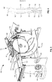
- FIG. 1 illustrates a side view of a conventional table saw 20.
- the table saw 20 includes a table 24, a saw blade 28, a lower guard 32, a riving knife 36, and an upper guard 40.
- the table 24 has an upper table top surface 44 configured to support a workpiece during cutting operations.
- the saw blade 28 is driven by a motor and drivetrain unit (not shown), which is located below the table 44.
- the motor and drivetrain rotates an output shaft (not shown), to which the saw blade 28 is clamped by a blade washer 48 to rotate the saw blade during cutting operations.
- the lower guard 32 of the table saw 20 includes a dust rip 52 and a lower dust chute 56.
- the dust rip 52 may be configured to guide particulates from the saw blade 28 towards the lower dust chute 56, which may be connected to a dust storage area (not shown) to store the dust and particulates for subsequent disposal.
- a single dust rip 52 is shown, though in other embodiments multiple dust rips 52 are installed on the lower guard 32.
- the upper guard 40 is positioned above the saw blade 28 and may be mounted to the riving knife 36.
- the upper guard 40 includes an upper dust chute 60 which collects dust and debris caught by the upper guard 40 and may direct the dust and debris to a storage area for subsequent disposal.
- FIG. 2 illustrates a table saw 100 not according to the present invention.
- the table saw 100 includes a base 104, a table 108, a generally planar saw blade 112, and an airflow management and upper guard system 116.
- the base 104 is configured to support the table 108 and to house the internal components of the table saw 100, including the motor and drive system 118 and a lower guard 120 ( FIG. 3 ).
- the table 108 includes an upper table top surface 124 configured to support a workpiece during cutting operations.
- An elongated rectangular saw blade opening 126 is defined in the table top surface 124 and configured such that the saw blade 112 extends through the saw blade opening 126.
- the airflow management and upper guard system 116 includes an upper guard 128, a riving knife 132, an elongated hollow member 136, also referred to herein as a tuning fork, and a dust cap 140.
- the upper guard 128 has two side pawls 144, 148 ( FIG. 2 ) positioned on opposite sides of the saw blade 112.
- the side pawls 144, 148 are pivotable about an axis parallel to the central axis of the saw blade 112 to enable a workpiece to be inserted under the side pawls 144, 148.
- the riving knife 132 is positioned behind the saw blade 112 to split the workpiece after it has been cut so that the saw blade 112 does not catch on the workpiece and eject a portion of the workpiece toward a user of the table saw 100.
- the tuning fork 136 may be mounted above the saw blade 112 on the riving knife 132, between the side pawls 144, 148 of the upper guard 128. As shown in the detail views of FIGS. 5-7 , the tuning fork 136 includes a first prong 164 and a second prong 168 defining an opening 172 therebetween. In some embodiments, the tuning fork 136 may include an end cap 174 ( FIG. 3 ) closing off a front end of the tuning fork 136, though other embodiments (for example FIGS. 5 and 6 ) may not include an end cap.
- the tuning fork 136 may be hollow to define an airflow channel 176 through the center of the tuning fork 136, between the prongs 164, 168 to enable flow of air through the tuning fork 136 to the dust cap 140. As best seen in FIG. 7 , the tuning fork 136 may incorporate hooks 178, to which the dust cap 140 is attached.
- the dust cap 140 fits inside the tuning fork 136, and may be connected to the tuning fork 136 by a snap fit connection, screws, and/or clips such as the hooks 178 shown in FIG. 7 , while in other embodiments the dust cap 140 and the tuning fork 136 may be integrally formed as a single piece. In some embodiments, the dust cap 140 may be moved downwardly to snap into connection with the tuning fork 136, in direction of arrow 179 ( FIG. 2 ), while in other embodiments the dust cap 140 may slide horizontally into clips of the tuning fork 136 to connect to the tuning fork 136.
- the dust cap 140 defines a plurality of windows 152, which are aligned with corresponding windows 154 defined in the tuning fork 136.
- the dust cap 140 further includes a dust hose connection 156 at an end behind the saw blade 112 to facilitate connection of the dust cap 140 to a vacuum hose 180 ( FIG. 8 ).
- the dust cap 140 may be hollow so that air, dust, and particulates flow from the flow channel 176 of the tuning fork 136, through the dust cap 140, and into the vacuum hose 180 via the dust hose connection 156.
- the dust cap 140 has an indicator line 160 on a length of a top surface of the dust cap 140.
- the indicator line 160 is aligned with the saw blade plane 162 ( FIG. 4 ) in which the saw blade 112 is positioned to provide a visual indication of the cutting line of the saw blade 112 beneath the dust cap 140 and upper guard 128.
- the dust cap 140 may include airflow ribs 162 ( FIG. 8 ) configured to guide airflow toward the rear portion of the dust cap and to the hose connection 156.
- the tuning fork 136 may also include airflow ribs (not shown) to guide the airflow within the tuning fork 136.
- the table saw 100 is activated by a user pressing a button or activating a switch 184.
- the motor of the saw 100 spins the saw blade 112, and a user pushes a workpiece across the table top surface 124 into the lower portion of the upper guard 128, urging the pawls 144, 148 to pivot upwardly and out of the way of the workpiece.
- the workpiece contacts the saw blade 112, the workpiece is cut and dust and particulates scatter within the upper guard 128.
- the spinning saw blade 112 ejects dust and particulates are upwardly toward the tuning fork 136 and dust cap 140.
- a vacuum hose 180 is connected to the dust hose connection 156 at one end and to a vacuum source 188 ( FIG.
- FIG. 9 depicts another airflow management and upper guard system 200, which can be used in the table saw 100 in place of the airflow management and upper guard system 116 described above.
- the embodiment of figure 9 is not according to the invention.
- the upper guard system 200 is mounted above a saw blade 204, and includes a tuning fork 208, a dust cap 212, and a hose connection 216.
- the tuning fork 208 is substantially similar to the tuning fork 136 described above.
- the dust cap 212 is configured to slide over the tuning fork 208 and connect to the hose connection 216.
- the hose connection 216 is connected at one end to the dust cap 212, and at the other end to a vacuum hose 220.
- the hose connection further includes a locking lever 224, which engages the dust cap 212 to lock the dust cap 212 in place.
- the locking lever 224 is pivotable about a pivot point 228.
- the dust cap 212 is configured to slide into position over the tuning fork 208 prior to a cutting operation, to the right in the view of FIG. 9 .
- the dust cap 212 engages the locking lever 224 of the hose connection 216 once the dust cap 212 is in position, and the locking lever 224 locks the dust cap 212 to the hose connection 216.
- the vacuum hose 220 is then connected to the opposite end of the hose connection 216, and the cutting operation can commence.
- a vacuum sucks air, dust, and particulates from the saw blade 204 through the tuning fork 208 and dust cap 212 and into the vacuum hose 220.
- the airflow management and upper guard system 200 can be disassembled for cleaning or other maintenance.
- the vacuum hose 220 is disconnected from the hose connection 216, which may then be pivoted counter-clockwise about the pivot point 228. Pivoting the hose connection 216 disengages the locking lever 224 from the dust cap 212.
- the dust cap 212 slides to the left in the view of FIG. 9 to be removed from the table saw for cleaning.
- the locking lever 224 is further configured to lock the upper guard (not shown in FIG. 9 ) in place. In such an embodiment, pivoting the hose connection 216 also releases the upper guard for cleaning.
- FIG. 10 Another embodiment of a tuning fork 240 and a dust cap 244 is illustrated in FIG. 10 .
- the embodiment of figure 10 is not according to the invention.
- the dust cap 244 is configured to attach to the top of the tuning fork 240.
- the tuning fork 240 has a first prong 248 and a second prong 252.
- Three openings 256, 260, 264 are defined between the first and second prongs 248, 252.
- the airflow urges dust and particulates into the dust cap 244, where the dust and particulates are captured by a vacuum in a manner similar to operation of the dust caps discussed above.
- the tuning fork 240 and the dust cap 244 may be integral within the upper guard system.
- FIGS. 11 and 12 Another embodiment of an elongated member or tuning fork 300 is illustrated in FIGS. 11 and 12 .
- the tuning fork 300 has a first prong 304 and a second prong 308, positioned above and on either side of a saw blade 312.
- the first and second prongs 304, 308 each include a passage or window (only the passage 316 of the first prong 304 is visible in FIG. 11 ).
- the tuning fork 300, including the prongs 304, 308, is hollow, defining an inner chamber 320.
- the tuning fork 300 includes a hose connection 324 configured to connect to a vacuum hose (not shown).
- the tuning fork 300 of FIGS. 11 and 12 therefore performs the functions of both the tuning forks and the dust caps of the embodiments described above.
- FIGS. 13 and 14 illustrate another embodiment of an airflow management and upper guard system 340 having side pawls 344 (only one is illustrated in FIGS. 13 and 14 ), which can be used in the table saw 100 of FIG. 2 in place of side pawls 144, 148.
- the embodiment of figures 13 and 14 is not according to the invention.
- the airflow management and upper guard system 340 also includes a tuning fork 352, a dust cap 356, a hose connection 358, and a riving knife 360, all of which are similar to those described above.
- the tuning fork 352, dust cap 356, and hose connection 358 may each be separate parts connected to one another.
- the tuning fork 352 and the dust cap 356 may be integrally formed as a single part.
- the tuning fork 352, the dust cap 356, and the hose connection 358 may all be integrally formed as a single part by, for example, plastic injection molding.
- the side pawls 344 are positioned with one on each side of a saw blade 348 and are affixed to the riving knife 360 at a pivot connection 364.
- the side pawls 344 are configured to pivot about the pivot connection 364 to enable a workpiece to slide underneath the side pawls 344.
- Each side pawl 344 has a plurality of curved airflow ribs 368 positioned inside the side pawl 344.
- the saw blade 348 During operation of the saw, the saw blade 348 generates airflow in a direction generally tangential to the outer circumference of the saw blade 348.
- the airflow including dust and debris particles, flows upwardly into the pawls 344.
- the airflow ribs 368 in the side pawls 344 redirect the airflow backward, toward the rear of the side pawls 344, tuning fork 352, and dust cap 356.
- the dust and particles are collected in the tuning fork 352 and dust cap 356 and pulled by the vacuum suction into a collection area.
- FIG. 15 illustrates another dust cap 400.
- the embodiment of figure 15 is not according to the invention.
- the dust cap 400 is substantially the same as the dust cap 136 described above with regard to FIGS. 2-4 and is mounted atop a tuning fork 402.
- the dust cap 400 includes an illumination system 404 at a front end of the dust cap 400.
- the illumination system 404 may include a power switch 408, a laser diode 412, and a LED light 416.
- the laser diode 412 is configured to project a laser line downwardly, partially through the tuning fork 402, to illuminate a line 422 on a workpiece 424 and table top 426 indicating the location of the cutting line.
- the LED light 416 is configured to project light downwardly through the tuning fork 402 to illuminate an area 428 of the workpiece 424 and table top 426 to enable a user to better see the cutting area.
- the power switch 408 is triggered to activate the LED light 416 and laser diode 412.
- the power switch 408 has multiple modes, to activate only one of the LED light 416 and the laser diode 412, or to alter the intensity of the light provided by the LED light 416.
- the laser diode 412 and the LED light 416 are powered by a battery located proximate to the illumination system, while in other embodiments the laser diode 412 and the LED light 416 are connected by a wire to the power supply for the table saw to which the dust cap 400 is attached.
- the dust cap 400 of FIG. 15 operates to pull dust and debris from the work area in a manner similar to that of the dust cap 140 of FIGS. 2 , 3 , and 8 , while also providing light for the work area and displaying a cutting line on the workpiece to enable improved cutting accuracy.
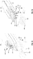
- FIG. 16 illustrates another embodiment of a hollow tuning fork 440.
- the tuning fork 440 is substantially the same as the tuning fork 300 described above with regard to FIG. 11 .
- the tuning fork 540 includes a first prong 444, a second prong 448, an illumination system 452 at a front end of the tuning fork 440, and a cover 456 over the front portion of the tuning fork 440.
- the illumination system 452 has two LED lights 460, one on each of the first and second prongs 444, 448.
- the LED lights 460 are configured to project light downwardly to illuminate an area 464 of a workpiece 468 and table top 470 to enable a user to better see the cutting area.
- the illumination system 452 includes a power switch located on the cover 456 or any other desired location, while in other embodiments the illumination system 452 is activated automatically when the saw is activated.
- the cover 456 is attached to a top surface of the tuning fork 440 and has a projection 472 extending from the center of the cover 456.
- the cover 456 and projection 472 have a central marking 476 to enable the user to visualize the cutting line of the table saw to which the tuning fork 440 is attached.
- the tuning fork 440 may include a laser diode (not shown) on a lower portion of the projection 472.
- the laser diode is configured to project a laser line 480 onto the workpiece 468 and table top 470 to further aid the user in visualizing the cutting line.
- the tuning fork 440 of FIG. 16 operates to pull dust and debris from the work area in a manner similar to that of the tuning fork of FIG. 11 , while also providing light for the work area and, in some embodiments, displaying a cutting line on the workpiece to enable improved cutting accuracy.
Landscapes
- Engineering & Computer Science (AREA)
- Mechanical Engineering (AREA)
- Life Sciences & Earth Sciences (AREA)
- Wood Science & Technology (AREA)
- Forests & Forestry (AREA)
- Physics & Mathematics (AREA)
- Optics & Photonics (AREA)
- Sawing (AREA)
Claims (7)
- Luftströmungshandhabungssystem für eine Tischkreissäge (100), Folgendes umfassend:ein längliches Element (300, 440), das einen hohlen ersten Zinken (304, 444) und einen hohlen zweiten Zinken (308, 448) enthält, wobei der erste und zweite Zinken (304, 308, 448) dazu ausgelegt sind, auf entgegengesetzten Seiten einer Sägeblattebene positioniert zu sein, in der ein Sägeblatt (112, 312) positioniert ist, und eine Öffnung dazwischen definieren,dadurch gekennzeichnet, dass der erste Zinken (304, 444) ein erstes Fenster (316) in einer Seite des ersten Zinkens (304, 444) enthält, das dazu ausgelegt ist, dem Sägeblatt (112, 312) zugewandt zu sein, und wobei der zweite Zinken (308, 448) ein zweites Fenster in einer Seite des zweiten Zinkens (308, 448) enthält, das dazu ausgelegt ist, dem Sägeblatt (112, 312) zugewandt zu sein,wobei das längliche Element (300, 440) einen Schlauchanschluss (324) enthält, der dazu ausgelegt ist, an einem Staubschlauch angeschlossen zu werden, wobei der Schlauchanschluss (324) durch das Innere des ersten und zweiten Zinkens (304, 444, 308, 448) mit dem ersten und zweiten Fenster (316) fluidisch verbunden ist, um eine Luftströmung vom ersten und zweiten Fenster (316) aufzunehmen.
- Luftströmungshandhabungssystem nach Anspruch 1, ferner Folgendes umfassend:
ein Spaltmesser, das dazu ausgelegt ist, sich in Umfangsrichtung um einen Teil des Sägeblatts (112, 312) zu erstrecken, wobei das längliche Element (300, 440) fest am Spaltmesser angebracht ist. - Luftströmungshandhabungssystem nach Anspruch 2, ferner Folgendes umfassend:
einen oberen Schutz, der eine erste und zweite Sperrklinke enthält, die am Spaltmesser angebracht sind und dazu ausgelegt sind, sich um eine Achse zu verschwenken, die im Allgemeinen normal zum Sägeblatt verläuft, wobei die erste und zweite Sperrklinke auf entgegengesetzten Seiten des Sägeblatts und des länglichen Elements (300, 440) positioniert sind. - Luftströmungshandhabungssystem nach Anspruch 3, wobei das längliche Element (300, 440), die Sperrklinke auf der ersten Seite und/oder die Sperrklinke auf der zweiten Seite mindestens eine Rippe enthalten, die dazu ausgelegt ist, den Luftstrom in Richtung des Schlauchanschlusses (324) zu leiten.
- Luftströmungshandhabungssystem nach Anspruch 1, wobei das längliche Element (300, 440) ein Licht enthält, das dazu ausgelegt ist, eine an das Sägeblatt (112, 312) angrenzende Fläche zu erleuchten.
- Luftströmungshandhabungssystem nach Anspruch 5, wobei das Licht dazu ausgelegt ist, eine Laserlinie entlang der Sägeblattebene abzugeben.
- Tischkreissäge (100), Folgendes umfassend:eine Tischplattenfläche, die eine längliche Blattöffnung definiert, in der ein Sägeblatt (112, 312) dazu ausgelegt ist, positioniert zu werden, wobei die Blattöffnung eine Sägeblatt(112, 312)-Ebene definiert, die rechtwinklig zur Tischplattenfläche verläuft und sich mittig entlang der Blattöffnung entlang einer Länge der Blattöffnung erstreckt;eine Vakuumquelle;ein Luftströmungshandhabungssystem nach einem der Ansprüche 1 bis 6.
Applications Claiming Priority (2)
| Application Number | Priority Date | Filing Date | Title |
|---|---|---|---|
| US201361921770P | 2013-12-30 | 2013-12-30 | |
| PCT/US2014/070866 WO2015102909A1 (en) | 2013-12-30 | 2014-12-17 | Airflow and illumination system for a table saw |
Publications (3)
| Publication Number | Publication Date |
|---|---|
| EP3099456A1 EP3099456A1 (de) | 2016-12-07 |
| EP3099456A4 EP3099456A4 (de) | 2017-08-02 |
| EP3099456B1 true EP3099456B1 (de) | 2020-07-15 |
Family
ID=53493891
Family Applications (1)
| Application Number | Title | Priority Date | Filing Date |
|---|---|---|---|
| EP14876944.1A Active EP3099456B1 (de) | 2013-12-30 | 2014-12-17 | Luftströmungs- und beleuchtungssystem für eine tischsäge |
Country Status (5)
| Country | Link |
|---|---|
| US (1) | US10328507B2 (de) |
| EP (1) | EP3099456B1 (de) |
| CN (1) | CN106163751B (de) |
| TW (1) | TWI639496B (de) |
| WO (1) | WO2015102909A1 (de) |
Families Citing this family (21)
| Publication number | Priority date | Publication date | Assignee | Title |
|---|---|---|---|---|
| US20100269353A1 (en) * | 2009-04-24 | 2010-10-28 | Martin Charles B | Portable cutting device with on-board debris collection |
| WO2015061370A1 (en) | 2013-10-21 | 2015-04-30 | Milwaukee Electric Tool Corporation | Adapter for power tool devices |
| KR102643822B1 (ko) | 2015-08-31 | 2024-03-07 | 제이피엘 글로벌, 엘엘씨 | 통합 다단 여과 시스템을 갖는 원형 쏘우 장치 |
| US10239136B2 (en) * | 2015-08-31 | 2019-03-26 | JPL Global, LLC | Circular saw apparatus with integrated multistage filtration system |
| JP6591263B2 (ja) * | 2015-11-16 | 2019-10-16 | Dmg森精機株式会社 | 切屑吸引用カバーおよび工作機械 |
| JP7035335B2 (ja) * | 2017-05-01 | 2022-03-15 | マックス株式会社 | 携帯用切断機 |
| CN207189852U (zh) | 2017-06-05 | 2018-04-06 | 米沃奇电动工具公司 | 台锯 |
| CN108284486B (zh) * | 2018-02-08 | 2023-04-07 | 永康市丛臻工具有限公司 | 一种无尘台锯台面除尘防护罩 |
| US11077507B1 (en) | 2018-07-09 | 2021-08-03 | Russell Matson | Dust collection systems and attachments for circular saws |
| KR102151865B1 (ko) * | 2019-01-23 | 2020-09-03 | 주식회사 준엔지니어링 | 판재절단용 전동식 원형톱장치 |
| EP3736086A1 (de) * | 2019-05-07 | 2020-11-11 | Hilti Aktiengesellschaft | Staubhaubenvorrichtung für ein werkzeuggerät, sowie seine verwendung und ein verfahren zur stauberfassung |
| DE102019134412B4 (de) | 2019-12-13 | 2023-12-14 | Festool Gmbh | Mobile Hand-Sägemaschine mit Vorritzaggregat und Werkzeugwechsel |
| DE102019134416A1 (de) * | 2019-12-13 | 2021-06-17 | Festool Gmbh | Mobile Hand-Sägemaschine mit Vorritzwerkzeug an Längsseite |
| US11224924B2 (en) * | 2020-01-20 | 2022-01-18 | Robert Benjamin Joiner | Table miter saw |
| CN112847662A (zh) * | 2021-01-12 | 2021-05-28 | 吴培聪 | 一种智能家具生产用板材的精确切割设备 |
| CN115502471B (zh) * | 2021-06-07 | 2025-08-26 | 永康市丛臻工具有限公司 | 一种自吸尘无尘台锯 |
| US11691311B2 (en) * | 2021-08-05 | 2023-07-04 | Benjamin K. Watson | Saw guard and methods of use thereof |
| USD1018614S1 (en) | 2021-08-05 | 2024-03-19 | Benjamin K. Watson | Saw guard |
| CN215615490U (zh) * | 2021-09-09 | 2022-01-25 | 南京德朔实业有限公司 | 一种台锯 |
| US12617116B2 (en) * | 2022-08-10 | 2026-05-05 | Techtronic Cordless Gp | Table saw including storage mount for blade guard assembly |
| WO2024086184A1 (en) * | 2022-10-17 | 2024-04-25 | JPL Global, LLC | Circular saw apparatus with an integrated dust collection system |
Family Cites Families (24)
| Publication number | Priority date | Publication date | Assignee | Title |
|---|---|---|---|---|
| FR2543873B1 (fr) * | 1983-04-05 | 1985-06-21 | Mugnier Joachim | Perfectionnements aux dispositifs d'aspiration pour scies circulaires |
| US4875398A (en) * | 1988-01-15 | 1989-10-24 | Atlantic Richfield Company | Retractable dust control hood and guard for rotary table saw |
| US5084972A (en) | 1991-01-25 | 1992-02-04 | Waugh Ricky L | Device for collecting dust from a portable circular saw |
| DE4205965C1 (en) * | 1992-02-27 | 1993-07-08 | Fried Kunststofftechnik Gmbh, 7068 Urbach, De | Protective hood for circular saw or combined circular cross-cut saw - has guide walls forming flow channels, which extend over top end of splitting wedge above table |
| US9586335B2 (en) | 2010-01-27 | 2017-03-07 | Sd3, Llc | Blade guard with dust collection |
| GB0502289D0 (en) * | 2005-02-04 | 2005-03-09 | Gmca Pty Ltd | Dust and debris extraction apparatus for power tool |
| US8069761B2 (en) * | 2005-04-18 | 2011-12-06 | Black & Decker Inc. | Dust collector |
| US7465328B2 (en) * | 2005-07-22 | 2008-12-16 | Black & Decker Inc. | Dust collector for a power tool |
| US7437981B2 (en) | 2005-11-21 | 2008-10-21 | Robert Bosch Gmbh | Modular guard system and apparatus for a power saw |
| US7600456B2 (en) | 2005-11-21 | 2009-10-13 | Robert Bosch Gmbh | Modular guard system for a power saw |
| US20070163408A1 (en) * | 2006-01-17 | 2007-07-19 | Buck William C | Table saw guard |
| US20090183377A1 (en) * | 2008-01-21 | 2009-07-23 | Michael Loveless | Dust shroud for circular saws |
| US7821012B2 (en) * | 2008-03-18 | 2010-10-26 | Semiconductor Energy Laboratory Co., Ltd. | Thin film transistor |
| US8516185B2 (en) * | 2009-07-16 | 2013-08-20 | Netlist, Inc. | System and method utilizing distributed byte-wise buffers on a memory module |
| US8082825B2 (en) * | 2009-06-09 | 2011-12-27 | Butler David J | Health and safety system for a table saw |
| US20110162501A1 (en) * | 2010-01-06 | 2011-07-07 | Credo Technology Corporation | Dust extraction blade guard system for power saws |
| US8752462B2 (en) * | 2010-08-13 | 2014-06-17 | Robert Bosch Gmbh | Dust management system in a table saw |
| US9558860B2 (en) | 2010-09-10 | 2017-01-31 | Samsung Electronics Co., Ltd. | Graphene-enhanced anode particulates for lithium ion batteries |
| US8726773B2 (en) * | 2010-10-19 | 2014-05-20 | Robert Bosch Gmbh | Table saw having airflow apparatus |
| CN201833433U (zh) * | 2010-11-02 | 2011-05-18 | 南京鑫业电动工具制造有限公司 | 一种自吸尘木工台锯 |
| CN201833432U (zh) * | 2010-11-02 | 2011-05-18 | 南京鑫业电动工具制造有限公司 | 一种自吸尘木工台锯 |
| US8616102B2 (en) | 2011-04-07 | 2013-12-31 | Robert Bosch Gmbh | Optical alignment device for a table saw |
| EP2969430B1 (de) * | 2013-03-12 | 2017-11-29 | Robert Bosch GmbH | Elektrowerkzeug mit entfernbarem staubfach |
| US9931678B2 (en) * | 2013-11-12 | 2018-04-03 | Inter-Source Recovery Systems | Pneumatic chip collector |
-
2014
- 2014-12-17 WO PCT/US2014/070866 patent/WO2015102909A1/en not_active Ceased
- 2014-12-17 US US15/108,446 patent/US10328507B2/en active Active
- 2014-12-17 CN CN201480071695.0A patent/CN106163751B/zh active Active
- 2014-12-17 EP EP14876944.1A patent/EP3099456B1/de active Active
- 2014-12-26 TW TW103145669A patent/TWI639496B/zh active
Non-Patent Citations (1)
| Title |
|---|
| None * |
Also Published As
| Publication number | Publication date |
|---|---|
| TWI639496B (zh) | 2018-11-01 |
| US10328507B2 (en) | 2019-06-25 |
| EP3099456A4 (de) | 2017-08-02 |
| CN106163751A (zh) | 2016-11-23 |
| CN106163751B (zh) | 2019-08-20 |
| US20160332244A1 (en) | 2016-11-17 |
| WO2015102909A1 (en) | 2015-07-09 |
| TW201540458A (zh) | 2015-11-01 |
| EP3099456A1 (de) | 2016-12-07 |
Similar Documents
| Publication | Publication Date | Title |
|---|---|---|
| US10328507B2 (en) | Airflow and illumination system for a table saw | |
| US6988435B2 (en) | Sawdust collection assembly for a compound miter saw | |
| US8371034B2 (en) | Dust collection cover attachable to cutter | |
| EP3741486B1 (de) | Klingenschutzgruppe | |
| JP4733952B2 (ja) | 切断機 | |
| US8079389B2 (en) | Vacuum attachment for router table | |
| US5235753A (en) | Circular saw lower guard chip deflector | |
| CN202147269U (zh) | 碎屑收集组件和具有碎屑收集组件的动力工具 | |
| US8782906B2 (en) | Saw assembly with pivot hinge dust port | |
| US20110162501A1 (en) | Dust extraction blade guard system for power saws | |
| US9089941B2 (en) | Circular saw guard system | |
| EP1834723B1 (de) | Stichsäge mit Vorrichtung zur Späneabfuhr | |
| US10682751B2 (en) | Screw gun multitool | |
| JP2003011101A (ja) | 手持ち式電動工具 | |
| EP2463049B1 (de) | Schneidemaschine | |
| US9931704B2 (en) | Line-of-sight blower for a power tool | |
| JP2010115876A (ja) | 丸鋸 | |
| JP4195474B2 (ja) | 切断機 | |
| JP3955877B2 (ja) | 切断機 | |
| US20130081288A1 (en) | Pipe Deburring Accessory for Circular Saw | |
| WO2017148340A1 (zh) | 电圆锯用集尘罩及集尘方法 | |
| JP5016008B2 (ja) | 切断機 | |
| JP4782819B2 (ja) | 切断機 | |
| JPH077121Y2 (ja) | 卓上切断機の切粉排出装置 | |
| JP2012152897A (ja) | 切断機 |
Legal Events
| Date | Code | Title | Description |
|---|---|---|---|
| PUAI | Public reference made under article 153(3) epc to a published international application that has entered the european phase |
Free format text: ORIGINAL CODE: 0009012 |
|
| STAA | Information on the status of an ep patent application or granted ep patent |
Free format text: STATUS: REQUEST FOR EXAMINATION WAS MADE |
|
| 17P | Request for examination filed |
Effective date: 20160801 |
|
| AK | Designated contracting states |
Kind code of ref document: A1 Designated state(s): AL AT BE BG CH CY CZ DE DK EE ES FI FR GB GR HR HU IE IS IT LI LT LU LV MC MK MT NL NO PL PT RO RS SE SI SK SM TR |
|
| AX | Request for extension of the european patent |
Extension state: BA ME |
|
| DAX | Request for extension of the european patent (deleted) | ||
| A4 | Supplementary search report drawn up and despatched |
Effective date: 20170629 |
|
| RIC1 | Information provided on ipc code assigned before grant |
Ipc: B27G 19/02 20060101ALI20170623BHEP Ipc: B27B 5/29 20060101AFI20170623BHEP |
|
| GRAP | Despatch of communication of intention to grant a patent |
Free format text: ORIGINAL CODE: EPIDOSNIGR1 |
|
| STAA | Information on the status of an ep patent application or granted ep patent |
Free format text: STATUS: GRANT OF PATENT IS INTENDED |
|
| INTG | Intention to grant announced |
Effective date: 20191024 |
|
| GRAJ | Information related to disapproval of communication of intention to grant by the applicant or resumption of examination proceedings by the epo deleted |
Free format text: ORIGINAL CODE: EPIDOSDIGR1 |
|
| STAA | Information on the status of an ep patent application or granted ep patent |
Free format text: STATUS: REQUEST FOR EXAMINATION WAS MADE |
|
| GRAP | Despatch of communication of intention to grant a patent |
Free format text: ORIGINAL CODE: EPIDOSNIGR1 |
|
| STAA | Information on the status of an ep patent application or granted ep patent |
Free format text: STATUS: GRANT OF PATENT IS INTENDED |
|
| INTG | Intention to grant announced |
Effective date: 20200205 |
|
| RAP1 | Party data changed (applicant data changed or rights of an application transferred) |
Owner name: ROBERT BOSCH GMBH |
|
| GRAS | Grant fee paid |
Free format text: ORIGINAL CODE: EPIDOSNIGR3 |
|
| GRAA | (expected) grant |
Free format text: ORIGINAL CODE: 0009210 |
|
| STAA | Information on the status of an ep patent application or granted ep patent |
Free format text: STATUS: THE PATENT HAS BEEN GRANTED |
|
| AK | Designated contracting states |
Kind code of ref document: B1 Designated state(s): AL AT BE BG CH CY CZ DE DK EE ES FI FR GB GR HR HU IE IS IT LI LT LU LV MC MK MT NL NO PL PT RO RS SE SI SK SM TR |
|
| REG | Reference to a national code |
Ref country code: GB Ref legal event code: FG4D Ref country code: CH Ref legal event code: EP |
|
| REG | Reference to a national code |
Ref country code: IE Ref legal event code: FG4D |
|
| REG | Reference to a national code |
Ref country code: DE Ref legal event code: R096 Ref document number: 602014067879 Country of ref document: DE |
|
| REG | Reference to a national code |
Ref country code: AT Ref legal event code: REF Ref document number: 1290490 Country of ref document: AT Kind code of ref document: T Effective date: 20200815 |
|
| REG | Reference to a national code |
Ref country code: LT Ref legal event code: MG4D |
|
| REG | Reference to a national code |
Ref country code: AT Ref legal event code: MK05 Ref document number: 1290490 Country of ref document: AT Kind code of ref document: T Effective date: 20200715 |
|
| REG | Reference to a national code |
Ref country code: NL Ref legal event code: MP Effective date: 20200715 |
|
| PG25 | Lapsed in a contracting state [announced via postgrant information from national office to epo] |
Ref country code: GR Free format text: LAPSE BECAUSE OF FAILURE TO SUBMIT A TRANSLATION OF THE DESCRIPTION OR TO PAY THE FEE WITHIN THE PRESCRIBED TIME-LIMIT Effective date: 20201016 Ref country code: FI Free format text: LAPSE BECAUSE OF FAILURE TO SUBMIT A TRANSLATION OF THE DESCRIPTION OR TO PAY THE FEE WITHIN THE PRESCRIBED TIME-LIMIT Effective date: 20200715 Ref country code: AT Free format text: LAPSE BECAUSE OF FAILURE TO SUBMIT A TRANSLATION OF THE DESCRIPTION OR TO PAY THE FEE WITHIN THE PRESCRIBED TIME-LIMIT Effective date: 20200715 Ref country code: NO Free format text: LAPSE BECAUSE OF FAILURE TO SUBMIT A TRANSLATION OF THE DESCRIPTION OR TO PAY THE FEE WITHIN THE PRESCRIBED TIME-LIMIT Effective date: 20201015 Ref country code: SE Free format text: LAPSE BECAUSE OF FAILURE TO SUBMIT A TRANSLATION OF THE DESCRIPTION OR TO PAY THE FEE WITHIN THE PRESCRIBED TIME-LIMIT Effective date: 20200715 Ref country code: PT Free format text: LAPSE BECAUSE OF FAILURE TO SUBMIT A TRANSLATION OF THE DESCRIPTION OR TO PAY THE FEE WITHIN THE PRESCRIBED TIME-LIMIT Effective date: 20201116 Ref country code: HR Free format text: LAPSE BECAUSE OF FAILURE TO SUBMIT A TRANSLATION OF THE DESCRIPTION OR TO PAY THE FEE WITHIN THE PRESCRIBED TIME-LIMIT Effective date: 20200715 Ref country code: LT Free format text: LAPSE BECAUSE OF FAILURE TO SUBMIT A TRANSLATION OF THE DESCRIPTION OR TO PAY THE FEE WITHIN THE PRESCRIBED TIME-LIMIT Effective date: 20200715 Ref country code: ES Free format text: LAPSE BECAUSE OF FAILURE TO SUBMIT A TRANSLATION OF THE DESCRIPTION OR TO PAY THE FEE WITHIN THE PRESCRIBED TIME-LIMIT Effective date: 20200715 Ref country code: BG Free format text: LAPSE BECAUSE OF FAILURE TO SUBMIT A TRANSLATION OF THE DESCRIPTION OR TO PAY THE FEE WITHIN THE PRESCRIBED TIME-LIMIT Effective date: 20201015 |
|
| PG25 | Lapsed in a contracting state [announced via postgrant information from national office to epo] |
Ref country code: IS Free format text: LAPSE BECAUSE OF FAILURE TO SUBMIT A TRANSLATION OF THE DESCRIPTION OR TO PAY THE FEE WITHIN THE PRESCRIBED TIME-LIMIT Effective date: 20201115 Ref country code: PL Free format text: LAPSE BECAUSE OF FAILURE TO SUBMIT A TRANSLATION OF THE DESCRIPTION OR TO PAY THE FEE WITHIN THE PRESCRIBED TIME-LIMIT Effective date: 20200715 Ref country code: LV Free format text: LAPSE BECAUSE OF FAILURE TO SUBMIT A TRANSLATION OF THE DESCRIPTION OR TO PAY THE FEE WITHIN THE PRESCRIBED TIME-LIMIT Effective date: 20200715 Ref country code: RS Free format text: LAPSE BECAUSE OF FAILURE TO SUBMIT A TRANSLATION OF THE DESCRIPTION OR TO PAY THE FEE WITHIN THE PRESCRIBED TIME-LIMIT Effective date: 20200715 |
|
| PG25 | Lapsed in a contracting state [announced via postgrant information from national office to epo] |
Ref country code: NL Free format text: LAPSE BECAUSE OF FAILURE TO SUBMIT A TRANSLATION OF THE DESCRIPTION OR TO PAY THE FEE WITHIN THE PRESCRIBED TIME-LIMIT Effective date: 20200715 |
|
| REG | Reference to a national code |
Ref country code: DE Ref legal event code: R097 Ref document number: 602014067879 Country of ref document: DE |
|
| PG25 | Lapsed in a contracting state [announced via postgrant information from national office to epo] |
Ref country code: CZ Free format text: LAPSE BECAUSE OF FAILURE TO SUBMIT A TRANSLATION OF THE DESCRIPTION OR TO PAY THE FEE WITHIN THE PRESCRIBED TIME-LIMIT Effective date: 20200715 Ref country code: DK Free format text: LAPSE BECAUSE OF FAILURE TO SUBMIT A TRANSLATION OF THE DESCRIPTION OR TO PAY THE FEE WITHIN THE PRESCRIBED TIME-LIMIT Effective date: 20200715 Ref country code: IT Free format text: LAPSE BECAUSE OF FAILURE TO SUBMIT A TRANSLATION OF THE DESCRIPTION OR TO PAY THE FEE WITHIN THE PRESCRIBED TIME-LIMIT Effective date: 20200715 Ref country code: RO Free format text: LAPSE BECAUSE OF FAILURE TO SUBMIT A TRANSLATION OF THE DESCRIPTION OR TO PAY THE FEE WITHIN THE PRESCRIBED TIME-LIMIT Effective date: 20200715 Ref country code: SM Free format text: LAPSE BECAUSE OF FAILURE TO SUBMIT A TRANSLATION OF THE DESCRIPTION OR TO PAY THE FEE WITHIN THE PRESCRIBED TIME-LIMIT Effective date: 20200715 Ref country code: EE Free format text: LAPSE BECAUSE OF FAILURE TO SUBMIT A TRANSLATION OF THE DESCRIPTION OR TO PAY THE FEE WITHIN THE PRESCRIBED TIME-LIMIT Effective date: 20200715 |
|
| PLBE | No opposition filed within time limit |
Free format text: ORIGINAL CODE: 0009261 |
|
| STAA | Information on the status of an ep patent application or granted ep patent |
Free format text: STATUS: NO OPPOSITION FILED WITHIN TIME LIMIT |
|
| PG25 | Lapsed in a contracting state [announced via postgrant information from national office to epo] |
Ref country code: AL Free format text: LAPSE BECAUSE OF FAILURE TO SUBMIT A TRANSLATION OF THE DESCRIPTION OR TO PAY THE FEE WITHIN THE PRESCRIBED TIME-LIMIT Effective date: 20200715 |
|
| 26N | No opposition filed |
Effective date: 20210416 |
|
| PG25 | Lapsed in a contracting state [announced via postgrant information from national office to epo] |
Ref country code: SK Free format text: LAPSE BECAUSE OF FAILURE TO SUBMIT A TRANSLATION OF THE DESCRIPTION OR TO PAY THE FEE WITHIN THE PRESCRIBED TIME-LIMIT Effective date: 20200715 |
|
| REG | Reference to a national code |
Ref country code: CH Ref legal event code: PL |
|
| PG25 | Lapsed in a contracting state [announced via postgrant information from national office to epo] |
Ref country code: SI Free format text: LAPSE BECAUSE OF FAILURE TO SUBMIT A TRANSLATION OF THE DESCRIPTION OR TO PAY THE FEE WITHIN THE PRESCRIBED TIME-LIMIT Effective date: 20200715 Ref country code: MC Free format text: LAPSE BECAUSE OF FAILURE TO SUBMIT A TRANSLATION OF THE DESCRIPTION OR TO PAY THE FEE WITHIN THE PRESCRIBED TIME-LIMIT Effective date: 20200715 |
|
| REG | Reference to a national code |
Ref country code: BE Ref legal event code: MM Effective date: 20201231 |
|
| PG25 | Lapsed in a contracting state [announced via postgrant information from national office to epo] |
Ref country code: IE Free format text: LAPSE BECAUSE OF NON-PAYMENT OF DUE FEES Effective date: 20201217 Ref country code: LU Free format text: LAPSE BECAUSE OF NON-PAYMENT OF DUE FEES Effective date: 20201217 |
|
| PG25 | Lapsed in a contracting state [announced via postgrant information from national office to epo] |
Ref country code: CH Free format text: LAPSE BECAUSE OF NON-PAYMENT OF DUE FEES Effective date: 20201231 Ref country code: LI Free format text: LAPSE BECAUSE OF NON-PAYMENT OF DUE FEES Effective date: 20201231 |
|
| PG25 | Lapsed in a contracting state [announced via postgrant information from national office to epo] |
Ref country code: TR Free format text: LAPSE BECAUSE OF FAILURE TO SUBMIT A TRANSLATION OF THE DESCRIPTION OR TO PAY THE FEE WITHIN THE PRESCRIBED TIME-LIMIT Effective date: 20200715 Ref country code: MT Free format text: LAPSE BECAUSE OF FAILURE TO SUBMIT A TRANSLATION OF THE DESCRIPTION OR TO PAY THE FEE WITHIN THE PRESCRIBED TIME-LIMIT Effective date: 20200715 Ref country code: CY Free format text: LAPSE BECAUSE OF FAILURE TO SUBMIT A TRANSLATION OF THE DESCRIPTION OR TO PAY THE FEE WITHIN THE PRESCRIBED TIME-LIMIT Effective date: 20200715 |
|
| PG25 | Lapsed in a contracting state [announced via postgrant information from national office to epo] |
Ref country code: MK Free format text: LAPSE BECAUSE OF FAILURE TO SUBMIT A TRANSLATION OF THE DESCRIPTION OR TO PAY THE FEE WITHIN THE PRESCRIBED TIME-LIMIT Effective date: 20200715 |
|
| PG25 | Lapsed in a contracting state [announced via postgrant information from national office to epo] |
Ref country code: BE Free format text: LAPSE BECAUSE OF NON-PAYMENT OF DUE FEES Effective date: 20201231 |
|
| PGFP | Annual fee paid to national office [announced via postgrant information from national office to epo] |
Ref country code: GB Payment date: 20241218 Year of fee payment: 11 |
|
| PGFP | Annual fee paid to national office [announced via postgrant information from national office to epo] |
Ref country code: FR Payment date: 20241219 Year of fee payment: 11 |
|
| PGFP | Annual fee paid to national office [announced via postgrant information from national office to epo] |
Ref country code: DE Payment date: 20260223 Year of fee payment: 12 |