EP3099506B1 - System für einen drucker mit einer druckträgerkantenführung, und drucker - Google Patents
System für einen drucker mit einer druckträgerkantenführung, und drucker Download PDFInfo
- Publication number
- EP3099506B1 EP3099506B1 EP14702251.1A EP14702251A EP3099506B1 EP 3099506 B1 EP3099506 B1 EP 3099506B1 EP 14702251 A EP14702251 A EP 14702251A EP 3099506 B1 EP3099506 B1 EP 3099506B1
- Authority
- EP
- European Patent Office
- Prior art keywords
- platen assembly
- printer
- edge guide
- platen
- guide
- Prior art date
- Legal status (The legal status is an assumption and is not a legal conclusion. Google has not performed a legal analysis and makes no representation as to the accuracy of the status listed.)
- Active
Links
- 239000000758 substrate Substances 0.000 title claims description 66
- 239000004033 plastic Substances 0.000 claims description 3
- 229920003023 plastic Polymers 0.000 claims description 3
- 239000002184 metal Substances 0.000 claims description 2
- 239000002991 molded plastic Substances 0.000 claims 1
- 239000000976 ink Substances 0.000 description 11
- 238000007639 printing Methods 0.000 description 11
- 239000004753 textile Substances 0.000 description 8
- 125000000391 vinyl group Chemical group [H]C([*])=C([H])[H] 0.000 description 6
- 229920002554 vinyl polymer Polymers 0.000 description 6
- 230000002745 absorbent Effects 0.000 description 3
- 239000002250 absorbent Substances 0.000 description 3
- 230000000712 assembly Effects 0.000 description 3
- 238000000429 assembly Methods 0.000 description 3
- 239000006260 foam Substances 0.000 description 3
- 239000000463 material Substances 0.000 description 3
- 239000012530 fluid Substances 0.000 description 2
- 230000012447 hatching Effects 0.000 description 2
- 239000004816 latex Substances 0.000 description 2
- 229920000126 latex Polymers 0.000 description 2
- 230000000149 penetrating effect Effects 0.000 description 2
- 238000011144 upstream manufacturing Methods 0.000 description 2
- 240000000254 Agrostemma githago Species 0.000 description 1
- 235000009899 Agrostemma githago Nutrition 0.000 description 1
- 239000006096 absorbing agent Substances 0.000 description 1
- 239000000443 aerosol Substances 0.000 description 1
- 238000005452 bending Methods 0.000 description 1
- 230000001419 dependent effect Effects 0.000 description 1
- -1 for example Substances 0.000 description 1
- 238000001746 injection moulding Methods 0.000 description 1
- 238000007641 inkjet printing Methods 0.000 description 1
- 238000012423 maintenance Methods 0.000 description 1
- 238000012986 modification Methods 0.000 description 1
- 230000004048 modification Effects 0.000 description 1
- 230000007704 transition Effects 0.000 description 1
Images


Classifications
-
- B—PERFORMING OPERATIONS; TRANSPORTING
- B41—PRINTING; LINING MACHINES; TYPEWRITERS; STAMPS
- B41J—TYPEWRITERS; SELECTIVE PRINTING MECHANISMS, i.e. MECHANISMS PRINTING OTHERWISE THAN FROM A FORME; CORRECTION OF TYPOGRAPHICAL ERRORS
- B41J3/00—Typewriters or selective printing or marking mechanisms characterised by the purpose for which they are constructed
- B41J3/407—Typewriters or selective printing or marking mechanisms characterised by the purpose for which they are constructed for marking on special material
- B41J3/4078—Printing on textile
-
- B—PERFORMING OPERATIONS; TRANSPORTING
- B41—PRINTING; LINING MACHINES; TYPEWRITERS; STAMPS
- B41J—TYPEWRITERS; SELECTIVE PRINTING MECHANISMS, i.e. MECHANISMS PRINTING OTHERWISE THAN FROM A FORME; CORRECTION OF TYPOGRAPHICAL ERRORS
- B41J11/00—Devices or arrangements of selective printing mechanisms, e.g. ink-jet printers or thermal printers, for supporting or handling copy material in sheet or web form
- B41J11/0045—Guides for printing material
-
- B—PERFORMING OPERATIONS; TRANSPORTING
- B41—PRINTING; LINING MACHINES; TYPEWRITERS; STAMPS
- B41J—TYPEWRITERS; SELECTIVE PRINTING MECHANISMS, i.e. MECHANISMS PRINTING OTHERWISE THAN FROM A FORME; CORRECTION OF TYPOGRAPHICAL ERRORS
- B41J11/00—Devices or arrangements of selective printing mechanisms, e.g. ink-jet printers or thermal printers, for supporting or handling copy material in sheet or web form
- B41J11/001—Handling wide copy materials
-
- B—PERFORMING OPERATIONS; TRANSPORTING
- B41—PRINTING; LINING MACHINES; TYPEWRITERS; STAMPS
- B41J—TYPEWRITERS; SELECTIVE PRINTING MECHANISMS, i.e. MECHANISMS PRINTING OTHERWISE THAN FROM A FORME; CORRECTION OF TYPOGRAPHICAL ERRORS
- B41J11/00—Devices or arrangements of selective printing mechanisms, e.g. ink-jet printers or thermal printers, for supporting or handling copy material in sheet or web form
- B41J11/0045—Guides for printing material
- B41J11/005—Guides in the printing zone, e.g. guides for preventing contact of conveyed sheets with printhead
-
- B—PERFORMING OPERATIONS; TRANSPORTING
- B41—PRINTING; LINING MACHINES; TYPEWRITERS; STAMPS
- B41J—TYPEWRITERS; SELECTIVE PRINTING MECHANISMS, i.e. MECHANISMS PRINTING OTHERWISE THAN FROM A FORME; CORRECTION OF TYPOGRAPHICAL ERRORS
- B41J11/00—Devices or arrangements of selective printing mechanisms, e.g. ink-jet printers or thermal printers, for supporting or handling copy material in sheet or web form
- B41J11/02—Platens
- B41J11/06—Flat page-size platens or smaller flat platens having a greater size than line-size platens
-
- B—PERFORMING OPERATIONS; TRANSPORTING
- B41—PRINTING; LINING MACHINES; TYPEWRITERS; STAMPS
- B41J—TYPEWRITERS; SELECTIVE PRINTING MECHANISMS, i.e. MECHANISMS PRINTING OTHERWISE THAN FROM A FORME; CORRECTION OF TYPOGRAPHICAL ERRORS
- B41J11/00—Devices or arrangements of selective printing mechanisms, e.g. ink-jet printers or thermal printers, for supporting or handling copy material in sheet or web form
- B41J11/0085—Using suction for maintaining printing material flat
Definitions
- a smooth hard vacuum platen may be desirable for printing on paper and vinyl substrates while a platen that includes an ink absorber may be desirable for printing on textiles and other porous substrates.
- Large format printers for example, may print on paper, vinyl and textiles in varying width supplied as roles of flexible web.
- the invention provides a printer including a system according to claim 1.
- Document US2013/136521 discloses a device for use in a printer that includes a platen having a surface over which a print substrate is moved through a print zone for printing on the substrate.
- a printer including a system has been developed to increase the versatility of printers for printing on different types of substrates.
- Inkjet printers using latex inks are capable of printing on a variety of very different substrates including, for example, paper, textiles, and vinyl. These types of print substrates each have unique characteristics. Accordingly, it is often desirable to specially configure the platen to a particular type of print substrate to better support or control the substrate through the print zone. Specially configured platens are particularly desirable for wide format printers, which may handle print substrates as wide as several meters. Currently, however, it is difficult to use the same wide format printer to print on disparate substrates, like paper, textiles and vinyl for example, because significant modifications may be made to the printer platen to achieve consistently good print quality.
- the printer including the system includes interchangeable platens to support different types of print substrates.
- a platen system for a wide format latex inkjet printer might include a group of three interchangeable platens specially configured for paper, textile and vinyl so that the printer can be readily adapted for printing on any of these three types of print substrate by replacing one platen assembly with another platen assembly.
- a special type of platen for use with porous substrates, e.g. textiles, which can collect and/or absorb ink or another printing fluid penetrating through the substrate, is also designated "a gutter” or a "gutter-type” platen in the context of this disclosure.
- each platen in the group can consist of multiple modules to more easily vary the width of the platen assembly to accommodate different size print substrates and/or different size printers by simply using more or fewer modules.
- the system further includes an edge guide associated with the platen assembly for guiding an edge of the print substrate so that the print substrate is kept flat as the substrate passes through the print zone during printing.
- the edge guide is fixed to the platen assembly such that it can be inserted into the printer and removed from the printer together with the platen assembly.
- printers examples of the printer are described below with reference to a wide format inkjet printer, such as a scanning printhead type printer or a page-wide array printer.
- the printer is not limited to such inkjet printers or even to inkjet printing, but may be implemented in other printers. Accordingly, the examples shown in the figures and described below illustrate but do not limit the invention, which is defined in the Claims following this Description.
- Fig. 1 illustrates an isometric view of a wide format inkjet printer implementing one example of the new system for supporting and guiding different types of print substrates.
- the printer 10 comprises a housing generally shown at 12, defining a feed opening 14 for passing a print substrate therethrough.
- a print zone 16 is visible in the feed opening, the print zone 16 comprising a first platen assembly 18 and a second platen assembly 20.
- the first platen assembly 18 can be a fixed platen and the second platen assembly 20 can be an interchangeable or replaceable platen assembly for accommodating different types of print media.
- Figs. 2 and 3 illustrate different types of interchangeable platen modules.
- Fig. 2 shows an example of an interchangeable platen module 20' having a relatively smooth and hard surface configured to support a paper or plastic print substrate
- Fig. 3 shows a second type of an interchangeable platen module 20" configured to support a porous print substrate, such as a woven or non-woven textile or foam.
- the second type of platen module 20" can be a gutter for collecting and absorbing residue ink penetrating through the print substrate.
- the interchangeable platen module 20' may comprise a collecting zone and/or absorbing foam.
- the gutter-type platen 20" can have a grid like surface for carrying the print substrate, said surface preventing that the substrate and edge holder come into contact with excess ink collected in the gutter and be soiled.
- the printer illustrated in Fig. 1 further comprises an operating panel/- display 22 and a slot 24 for receiving ink cartridges.
- the printer 10 also includes a group of multiple printheads, for example to dispense different color inks, mounted on a carriage over the print zone 16.
- a substrate transport in the printer 10 includes a web supply roller and a web take-up roller.
- a web print substrate extends from supply roller over the print zone 16 and intermediate rollers to take-up roller. Intermediate rollers may be used, for example, to help control the direction and tension of web through a print zone 16 over platens 18, 20.
- Printheads dispense ink as they are scanned back and forth on carriage across substrate as it passes over platen 20 through print zone 16.
- An air pump or other suitable vacuum source can be operatively coupled to platens 18 and/or 20 through a system of air passages (not shown) and controls (not shown) may be used to exert a hold-down force on print substrate as necessary or desirable for some printing operations.
- the print zone 16 includes the first, fixed platen assembly 18 and the second, replaceable platen assembly 20.
- “fixed” means not easily removed and “replaceable” or “interchangeable” means easily installed and removed.
- the replaceable platen assembly 20 in Fig. 1 represents multiple interchangeable platens each easily installed into and removed from the printer 10, for example using quick release fasteners.
- the fixed platen assembly 18, by contrast, is a fixed part of the printer 10.
- the platen assembly 18 represents generally a fixed part of the printer 10 that is not designed to be removed or replaced regularly like the replaceable platen assembly 20.
- the replaceable platen assembly 20 is positioned directly under printheads and the fixed platen assembly 18 is positioned downstream from the replaceable platen assembly 20.
- the use of a fixed platen assembly 18 may help minimize the area needed for, and thus the size of, replaceable platen assembly 20.
- replaceable platen assembly 20 may be constrained more closely to the area directly under printheads where ink is dispensed on to substrate. If the fixed platen assembly 18 is used, it may be positioned downstream from the replaceable platen assembly 20, as shown or at other suitable locations upstream from the platen assembly 20 or on both sides of the platen assembly 20.
- Upstream and “downstream” refer to the direction substrate moves through the print zone 16.
- the direction print substrate moves through the print zone 16 is indicated by arrows 26 in Fig. 1 .
- “Length” is the direction the substrate moves through print zone.
- “Width” is perpendicular to the direction the substrate moves through the print zone 16.
- the system of this example includes a group of at least two interchangeable platens 20', 20", for example a rigid vacuum platen 20', for example to support paper and other cockle prone print substrates, or a flat vacuum platen 20', for example to support vinyl print substrates (shown individually in Fig. 2 ); and an absorbent platen or gutter-type platen 20", for example to support textiles and other porous print substrates (shown individually in Fig. 3 ).
- the group of interchangeable platens 20', 20" shown in Figs. 2 and 3 are just one example group of interchangeable platens for the platen system.
- the systems of this disclosure might include more interchangeable platens, and/or differently configured interchangeable platens than those shown.
- Each platen may be composed of a number of platen modules.
- Fig. 4 shows an isometric view of a replaceable platen module in greater detail.
- At least one replaceable platen module 28 can form part of the platen 20 wherein a number of such modules can be fitted side to side to vary the width of the platen to accommodate different size print substrates and/or different size printers compared to one-piece platens.
- the width of the overall platen may be expanded or contracted simply by using more or fewer modules 28.
- the platen module 28 can be fixed to the printer via flanges 30 and additionally can be mounted to a printer structure using quick release fasteners or other fastening means, as described in patent application USSN 13/718747, filed on December 18, 2012 , and entitled "Interchangeable printer platen", published as US 2014/0165865 .
- the platen module 28 comprises a guide rail 32 for slidably fixing an edge guide, as described further below.
- guide rail or another guide structure may be provided elsewhere on the replaceable platen assembly.
- Fig. 5 illustrates a sectional view of part of a printer according to one example.
- Fig. 5 shows the replaceable platen assembly 20 including a guide rail 32, similar to the one shown in Fig. 4 .
- the platen assembly 20 is fixed to a printer structure 34 via the flange 30 of the platen assembly 20 wherein this fixture can be released easily.
- Optional fastening means such as quick-release fasteners, can be used.
- the structure 34 is a fixed part of the printer and maybe fixed to or integral with fixed platen 18. Vacuum air passages (not shown) in the structure 34 and platens allow to apply a vacuum to print substrate as necessary or desirable to help control the print substrate moving across the platen assembly.
- the replaceable platen assembly 20 may include corresponding vacuum passages (not shown) for applying a vacuum to the substrate and/or extract aerosol released from the ink or other printing fluid.
- a vacuum passages not shown
- the platen assembly 20 including possibly several platen modules 28, guide rail 32 and edge guide assembly (described below) together form a "removable print zone" which can be removed and interchanged whereas the remaining parts, such as structure 34, remain in the printer.
- Fig. 5 further shows an edge guide assembly 44 associated with the guide rail 32 for guiding an edge of the print substrate, holding down the substrate on the platen assembly 20 so as to keep the substrate flat against the platen as the substrate passes through the print zone during printing.
- the edge guide assembly 44 comprises an engagement component 46 for engagement with the guide rail 32 and a holding component 48 connected to or integrated with the engagement component 46 for holding down the substrate.
- the engagement component 46 includes a groove 50 for engagement with the guide rail 32 so that the edge guide assembly 44 can slide along guide rail 32. Additionally, means for fixing the edge guide assembly 44 at a position along guide rail 32 can be provided.
- the holding component 48 in the example shown in Figs. 5 to 7 , is a part separate from the engagement component 46 and is fixed thereto by screws 52 (see Fig.
- the engagement component 46 may be formed by injection molding from a plastic material so as to be relatively rigid; and the holding component 48 may be formed from a sheet metal, providing a resilient force for clamping a substrate between the platen assembly 20 and a flexible holding tongue 54.
- the edge guide assembly 44 is fixed to the platen assembly 20 along only one (trailing) edge thereof (in the direction of print substrate movement) and extends across the whole or substantially the whole length of the platen assembly 20 from said side (see Fig. 6 ).
- This configuration of the replaceable platen assembly 20, with the edge guide assembly 44 fixed to the trailing edge thereof, allows to use a printer configuration using the drive roller 56 for print substrate transport which extends along only the (leading) edge of the platen assembly 20, opposite to the guide rail 32.
- a drive roller 56 in which the roller is not continuous and fingers 58 extend into grooves 60 provided in the drive roller 56 so as to ensure a smooth transition of the print substrate from the drive roller to the platen assembly 20 and vice versa (see Fig. 6 ).
- the engagement component and holding component may be made from different materials, may be made from more than two parts, or may be integrally formed. It is also possible to provide a fixture between the edge guide assembly and the platen assembly so that the edge guide is fixed at both longitudinal sides of the platen assembly 20. If the printer is dedicated for only substrates of identical widths, the edge guide assembly also need not be slidable along the width of the platen assembly 20 or even could be fixed at the short traverse side edges of the platen assembly. Also the platen/drive roller configuration can vary where it is not necessary to have the fingers 58 shown in Fig. 6 , but it also would be possible to provide an entry (or exit) drive roller e.g. below the platen where the print substrate is pulled across the print zone.
- the replaceable platen assembly 20 may comprise a platen or platen modules having a relatively hard rigid surface or a gutter-type platen or platen modules, with or without an additional absorbent material.
- the gutter-type platen can be configured such that the holding component 48 may not touch any stained surfaces or foams for collecting and/or absorbing ink which penetrates through an absorbent print substrate. This can be achieved, for example, by providing the gutter-type platen with a grid-like surface.
- the edge guide assembly 44 is fixed to the replaceable platen assembly 20 in such a way that it is easily inserted into the printer and removed from the printer together with the replaceable platen assembly. It is possible to provide a printer with a set of several interchangeable platens or platen modules which are provided with dedicated edge guide assemblies 44, wherein the configuration of each of the edge guides can be identical between different platens. This allows easily inserting and removing the platen assembly and also allows easily replacing and exchanging edge guide assemblies between different platen assemblies.
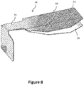
- Fig. 8 illustrates an example of the holding component 48 having zones of different rigidity wherein a zone of higher rigidity 60 is illustrated by densely spaced hatching and a zone of lower rigidity 58 is illustrated by more loosely spaced hatching.
- the less rigid zone 58 allows flexing of the holding component 48 and the more rigid zone 60 ensures that the tongue of the holding component remains relatively flat to hold down side edges of the print substrate.
- the cross hatched illustration 54' of the holding tongue 54 represents the tongue in a relaxed state whereas the hatched illustration 54 represents the tongue in a slightly deflected state for clamping a print substrate.
Landscapes
- Engineering & Computer Science (AREA)
- Textile Engineering (AREA)
- Handling Of Sheets (AREA)
Claims (12)
- Drucker, der ein System beinhaltet, Folgendes umfassend:eine entfernbare Plattenanordnung (20); undeine Kantenführung (44), die der Plattenanordnung (20) zugeordnet ist, wobei die Kantenführung (44) zum Führen einer Kante eines Drucksubstrats und zum Niederhalten von Kanten des Drucksubstrats auf der entfernbaren Plattenanordnung (20) konfiguriert ist;wobei die Kantenführung (44) an der Plattenanordnung (20) derart befestigt ist, dass die Kantenführung (44) zusammen mit der Plattenanordnung (20) in den Drucker eingesetzt und aus dem Drucker entfernt wird.
- Drucker nach Anspruch 1, wobei die entfernbare Plattenanordnung (20) eine Anzahl von Plattenmodulen (28) umfasst, die angepasst sind, um Seite an Seite zusammenzupassen, um die Breite der Plattenanordnung (20) zu variieren, um Drucksubstrate unterschiedlicher Größe und/oder Drucker unterschiedlicher Größe aufzunehmen.
- Drucker nach Anspruch 1, wobei das System eine Gruppe untereinander austauschbarer Platten (20', 20") beinhaltet, wobei jede eine unterschiedliche Art von Drucksubstrat trägt, und wobei eine ersten Kantenführung (44) einer ersten der austauschbaren Platten (20') zugeordnet ist und eine zweite Kantenführung (44) einer zweiten der austauschbaren Platten (20") zugeordnet ist.
- Drucker nach Anspruch 3, wobei die erste Kantenführung (44) und die zweite Kantenführung (44) eine identische Befestigungsanordnung zum Befestigen der ersten und der zweiten Kantenführung an der Plattenanordnung aufweisen.
- Drucker nach Anspruch 1, wobei das System eine Gruppe austauschbarer Platten (20', 20") beinhaltet, wobei jede konfiguriert ist, um eine unterschiedliche Art von Drucksubstrat zu tragen, und wobei eine Kantenführung (44) wahlweise einer ersten der austauschbaren Platten (20') zugeordnet ist und eine zweite Kantenführung (44) einer zweiten der austauschbaren Platten (20") zugeordnet ist.
- Drucker nach Anspruch 1, wobei
die Plattenanordnung (20) eine Führungsstruktur (32) entlang wenigstens eines Teils einer Längsseite davon umfasst und
die Kantenführung (44) eine Eingriffskomponente (46) für einen Eingriff mit der Führungsstruktur (32) umfasst und wobei die Kantenführung (44) entlang wenigstens eines Teils der Breite der Plattenanordnung (20) verschiebbar ist. - Drucker nach Anspruch 6, wobei sich die Kantenführung (44) von der Längsseite über die Plattenanordnung (20) in einer Längsrichtung davon erstreckt und nicht an einer gegenüberliegenden Längsseite der Plattenanordnung (20) befestigt ist.
- Drucker nach Anspruch 1, wobei
die Plattenanordnung (20) eine Führungsschiene (32) entlang wenigstens eines Teils einer Längsseite davon umfasst, wobei die Führungsschiene (32) sich von einer Unterseite der Plattenanordnung (20) erstreckt, und
die Kantenführung (44) eine Eingriffsnut (50) für den Eingriff mit der Führungsschiene umfasst, wobei die Kantenführung entlang wenigstens eines Teils der Breite der Plattenanordnung (20) verschiebbar ist. - Drucker nach Anspruch 1, wobei die Kantenführung (44) zusätzlich durch wenigstens einen Bolzen an der Plattenanordnung (20) befestigt ist.
- Drucker nach Anspruch 1, wobei die Kantenführung (44) eine Eingriffskomponente (46) für den Eingriff mit einer entsprechenden Führungsstruktur an einer Längsseite der Plattenanordnung (20) umfasst,
wobei die Kantenführung (44) konfiguriert ist, um relativ zu der Plattenanordnung (20) entlang einer Breite der Führungsstruktur verschiebbar zu sein; und
wobei die Kantenführung (44) konfiguriert ist, um an der einen Längsseite der Plattenanordnung (20) getragen zu werden, und sich von der Längsseite über die Plattenanordnung (20) in einer Längsrichtung davon erstreckt; und
wobei die Kantenführung (44) konfiguriert ist, um an der entfernbaren Plattenanordnung (20) angebracht zu bleiben, wenn die Plattenanordnung (20) aus dem Drucker entfernt wird. - Drucker nach Anspruch 10, wobei die Kantenführung (44) eine Haltekomponente (48) umfasst, die mit der Eingriffskomponente (46) verbunden oder in dieser integriert ist, wobei die Kantenführung auf der einen Längsseite der Plattenanordnung (20) getragen wird, sodass die Haltekomponente (48) parallel zu und von einer Oberfläche der Plattenanordnung (20) beabstandet ist, wobei die Haltekomponente (48) konfiguriert ist, um eine Niederhaltkraft auf das Drucksubstrat auszuüben, wobei die Haltekomponente eine Luftpumpe oder eine andere Vakuumquelle beinhaltet, die mit der Plattenanordnung (20) durch ein System von Luftkanälen und Steuerungen wirkverbunden ist.
- Drucker nach Anspruch 11, wobei
die Eingriffskomponente (46) ein gegossenes Kunststoffteil mit einer Nut für den Eingriff mit einer entsprechenden Führungsschiene ist, die an einer Unterseite der Plattenanordnung (20) bereitgestellt ist; und
die Haltekomponente (48) ein Metall- oder Kunststoffteil mit einem relativ flexiblen Abschnitt, der mit der Eingriffskomponente (46) verbunden ist, und einem relativ starren Abschnitt, der sich über die Oberfläche der Plattenanordnung (20) erstreckt, ist.
Applications Claiming Priority (1)
| Application Number | Priority Date | Filing Date | Title |
|---|---|---|---|
| PCT/EP2014/051810 WO2015113605A1 (en) | 2014-01-30 | 2014-01-30 | A system for a printer, a printer and a print substrate edge guide |
Publications (2)
| Publication Number | Publication Date |
|---|---|
| EP3099506A1 EP3099506A1 (de) | 2016-12-07 |
| EP3099506B1 true EP3099506B1 (de) | 2020-02-26 |
Family
ID=50031333
Family Applications (1)
| Application Number | Title | Priority Date | Filing Date |
|---|---|---|---|
| EP14702251.1A Active EP3099506B1 (de) | 2014-01-30 | 2014-01-30 | System für einen drucker mit einer druckträgerkantenführung, und drucker |
Country Status (4)
| Country | Link |
|---|---|
| US (1) | US9868301B2 (de) |
| EP (1) | EP3099506B1 (de) |
| CN (1) | CN105934351B (de) |
| WO (1) | WO2015113605A1 (de) |
Families Citing this family (3)
| Publication number | Priority date | Publication date | Assignee | Title |
|---|---|---|---|---|
| EP3744531A1 (de) * | 2015-10-23 | 2020-12-02 | Agfa Nv | Glasplatten-tintenstrahldruckvorrichtung |
| EP3305533B1 (de) | 2016-10-04 | 2021-02-17 | Canon Production Printing Holding B.V. | Verfahren zur verarbeitung einer bahn in einer vorrichtung |
| WO2019078827A1 (en) * | 2017-10-17 | 2019-04-25 | Hewlett-Packard Development Company, L.P. | UV-CURABLE INK JET INKS |
Citations (1)
| Publication number | Priority date | Publication date | Assignee | Title |
|---|---|---|---|---|
| US20130136521A1 (en) * | 2011-11-29 | 2013-05-30 | Daniel Gutierrez Garcia | Print substrate edge guide |
Family Cites Families (12)
| Publication number | Priority date | Publication date | Assignee | Title |
|---|---|---|---|---|
| US6000786A (en) | 1995-09-19 | 1999-12-14 | Array Printers Publ. Ab | Method and apparatus for using dual print zones to enhance print quality |
| JP3609500B2 (ja) | 1995-10-11 | 2005-01-12 | 積水化学工業株式会社 | 軒樋継手 |
| US5838338A (en) | 1996-05-30 | 1998-11-17 | Hewlett-Packard Company | Adaptive media handling system for printing mechanisms |
| US6594027B1 (en) | 1999-04-23 | 2003-07-15 | Hewlett-Packard Company | Image forming systems, methods of handling media, and methods of identifying locations of interchangeable media handling devices relative to one another |
| US6361230B1 (en) | 1999-09-17 | 2002-03-26 | Macdermid Acumen, Inc. | Printing zone specially adapted for textile printing media |
| US6857803B2 (en) * | 2001-01-08 | 2005-02-22 | Vutek, Inc. | Printing system web guide with a removable platen |
| JP3941104B2 (ja) | 2002-06-11 | 2007-07-04 | ブラザー工業株式会社 | インクジェット記録装置 |
| US7591533B2 (en) | 2004-01-21 | 2009-09-22 | Silverbrook Research Pty Ltd | Printhead assembly with print media guide |
| WO2006026839A2 (en) * | 2004-09-09 | 2006-03-16 | Mutoh Europe Nv | Device for attaching a printing media roll to a shaft |
| EP1721749B1 (de) * | 2005-05-09 | 2010-07-28 | Agfa Graphics N.V. | Transportvorrichtung für ein Aufzeichnungsmedium eines digitalen Druckers |
| US7695204B2 (en) | 2005-09-12 | 2010-04-13 | Silverbrook Research Pty Ltd | Wide format printer having alternative print zone arrangement |
| US9145002B2 (en) | 2012-12-18 | 2015-09-29 | Hewlett-Packard Development Company, L.P. | Interchangeable printer platens |
-
2014
- 2014-01-30 EP EP14702251.1A patent/EP3099506B1/de active Active
- 2014-01-30 US US15/113,159 patent/US9868301B2/en active Active
- 2014-01-30 CN CN201480074577.5A patent/CN105934351B/zh not_active Expired - Fee Related
- 2014-01-30 WO PCT/EP2014/051810 patent/WO2015113605A1/en not_active Ceased
Patent Citations (1)
| Publication number | Priority date | Publication date | Assignee | Title |
|---|---|---|---|---|
| US20130136521A1 (en) * | 2011-11-29 | 2013-05-30 | Daniel Gutierrez Garcia | Print substrate edge guide |
Also Published As
| Publication number | Publication date |
|---|---|
| US20170136786A1 (en) | 2017-05-18 |
| EP3099506A1 (de) | 2016-12-07 |
| WO2015113605A1 (en) | 2015-08-06 |
| CN105934351B (zh) | 2018-01-16 |
| US9868301B2 (en) | 2018-01-16 |
| CN105934351A (zh) | 2016-09-07 |
Similar Documents
| Publication | Publication Date | Title |
|---|---|---|
| US9145002B2 (en) | Interchangeable printer platens | |
| EP1905710B1 (de) | Blattfördervorrichtung | |
| JP2001063076A (ja) | インクノズルおよび側溝を有するプリントヘッド用の連続印字型インクジェットプリンタのメンテナンスまたはクリーニングシステム | |
| EP1967374A1 (de) | Förderband zum verbesserten Drucken einer Medienbahn in einer Druckmaschine | |
| EP3354463B1 (de) | Aufzeichnungskopfrückgewinnungssystem, kopfreinigungsmechanismus und tintenstrahlaufzeichnungsvorrichtung damit | |
| EP3099506B1 (de) | System für einen drucker mit einer druckträgerkantenführung, und drucker | |
| JP5538859B2 (ja) | 記録装置 | |
| JP6079355B2 (ja) | 印刷装置 | |
| EP2773509B1 (de) | Abdeckung für eine druckerplatte | |
| US7188927B2 (en) | Printhead wiper cleaning mechanism for an imaging apparatus | |
| JP2018158477A (ja) | インクジェットプリンタ | |
| US6340218B1 (en) | Single-pass wiping system for inkjet printheads | |
| JP4765969B2 (ja) | インクジェット記録装置 | |
| US9434186B2 (en) | Print substrate edge holder | |
| US9156269B2 (en) | Liquid ejection apparatus | |
| JP4967695B2 (ja) | クリーニングユニット、記録装置及びクリーニング方法 | |
| JP2018164980A (ja) | インクジェットプリンタ | |
| JP2005205631A (ja) | インクジェットプリンタ | |
| JP2009279780A (ja) | インクジェットプリンタ | |
| WO2017157452A1 (en) | Holder device for a printer | |
| US20210379912A1 (en) | Cutter assembly and printer | |
| EP3141390A1 (de) | Flüssigkeitsausstossvorrichtung | |
| US11413881B2 (en) | Direct-to-garment printing with stationary print nozzles | |
| JP2025184116A (ja) | 液体吐出装置 | |
| JP2025184117A (ja) | 交換ユニット |
Legal Events
| Date | Code | Title | Description |
|---|---|---|---|
| PUAI | Public reference made under article 153(3) epc to a published international application that has entered the european phase |
Free format text: ORIGINAL CODE: 0009012 |
|
| STAA | Information on the status of an ep patent application or granted ep patent |
Free format text: STATUS: REQUEST FOR EXAMINATION WAS MADE |
|
| 17P | Request for examination filed |
Effective date: 20160608 |
|
| AK | Designated contracting states |
Kind code of ref document: A1 Designated state(s): AL AT BE BG CH CY CZ DE DK EE ES FI FR GB GR HR HU IE IS IT LI LT LU LV MC MK MT NL NO PL PT RO RS SE SI SK SM TR |
|
| AX | Request for extension of the european patent |
Extension state: BA ME |
|
| DAX | Request for extension of the european patent (deleted) | ||
| STAA | Information on the status of an ep patent application or granted ep patent |
Free format text: STATUS: EXAMINATION IS IN PROGRESS |
|
| 17Q | First examination report despatched |
Effective date: 20180717 |
|
| RAP1 | Party data changed (applicant data changed or rights of an application transferred) |
Owner name: HEWLETT-PACKARD DEVELOPMENT COMPANY, L.P. |
|
| GRAP | Despatch of communication of intention to grant a patent |
Free format text: ORIGINAL CODE: EPIDOSNIGR1 |
|
| STAA | Information on the status of an ep patent application or granted ep patent |
Free format text: STATUS: GRANT OF PATENT IS INTENDED |
|
| INTG | Intention to grant announced |
Effective date: 20191015 |
|
| GRAS | Grant fee paid |
Free format text: ORIGINAL CODE: EPIDOSNIGR3 |
|
| GRAA | (expected) grant |
Free format text: ORIGINAL CODE: 0009210 |
|
| STAA | Information on the status of an ep patent application or granted ep patent |
Free format text: STATUS: THE PATENT HAS BEEN GRANTED |
|
| AK | Designated contracting states |
Kind code of ref document: B1 Designated state(s): AL AT BE BG CH CY CZ DE DK EE ES FI FR GB GR HR HU IE IS IT LI LT LU LV MC MK MT NL NO PL PT RO RS SE SI SK SM TR |
|
| REG | Reference to a national code |
Ref country code: GB Ref legal event code: FG4D |
|
| REG | Reference to a national code |
Ref country code: CH Ref legal event code: EP |
|
| REG | Reference to a national code |
Ref country code: AT Ref legal event code: REF Ref document number: 1237157 Country of ref document: AT Kind code of ref document: T Effective date: 20200315 |
|
| REG | Reference to a national code |
Ref country code: IE Ref legal event code: FG4D |
|
| REG | Reference to a national code |
Ref country code: DE Ref legal event code: R096 Ref document number: 602014061465 Country of ref document: DE |
|
| PG25 | Lapsed in a contracting state [announced via postgrant information from national office to epo] |
Ref country code: NO Free format text: LAPSE BECAUSE OF FAILURE TO SUBMIT A TRANSLATION OF THE DESCRIPTION OR TO PAY THE FEE WITHIN THE PRESCRIBED TIME-LIMIT Effective date: 20200526 Ref country code: FI Free format text: LAPSE BECAUSE OF FAILURE TO SUBMIT A TRANSLATION OF THE DESCRIPTION OR TO PAY THE FEE WITHIN THE PRESCRIBED TIME-LIMIT Effective date: 20200226 Ref country code: RS Free format text: LAPSE BECAUSE OF FAILURE TO SUBMIT A TRANSLATION OF THE DESCRIPTION OR TO PAY THE FEE WITHIN THE PRESCRIBED TIME-LIMIT Effective date: 20200226 |
|
| REG | Reference to a national code |
Ref country code: NL Ref legal event code: MP Effective date: 20200226 |
|
| REG | Reference to a national code |
Ref country code: LT Ref legal event code: MG4D |
|
| PG25 | Lapsed in a contracting state [announced via postgrant information from national office to epo] |
Ref country code: HR Free format text: LAPSE BECAUSE OF FAILURE TO SUBMIT A TRANSLATION OF THE DESCRIPTION OR TO PAY THE FEE WITHIN THE PRESCRIBED TIME-LIMIT Effective date: 20200226 Ref country code: GR Free format text: LAPSE BECAUSE OF FAILURE TO SUBMIT A TRANSLATION OF THE DESCRIPTION OR TO PAY THE FEE WITHIN THE PRESCRIBED TIME-LIMIT Effective date: 20200527 Ref country code: BG Free format text: LAPSE BECAUSE OF FAILURE TO SUBMIT A TRANSLATION OF THE DESCRIPTION OR TO PAY THE FEE WITHIN THE PRESCRIBED TIME-LIMIT Effective date: 20200526 Ref country code: IS Free format text: LAPSE BECAUSE OF FAILURE TO SUBMIT A TRANSLATION OF THE DESCRIPTION OR TO PAY THE FEE WITHIN THE PRESCRIBED TIME-LIMIT Effective date: 20200626 Ref country code: LV Free format text: LAPSE BECAUSE OF FAILURE TO SUBMIT A TRANSLATION OF THE DESCRIPTION OR TO PAY THE FEE WITHIN THE PRESCRIBED TIME-LIMIT Effective date: 20200226 Ref country code: SE Free format text: LAPSE BECAUSE OF FAILURE TO SUBMIT A TRANSLATION OF THE DESCRIPTION OR TO PAY THE FEE WITHIN THE PRESCRIBED TIME-LIMIT Effective date: 20200226 |
|
| PG25 | Lapsed in a contracting state [announced via postgrant information from national office to epo] |
Ref country code: NL Free format text: LAPSE BECAUSE OF FAILURE TO SUBMIT A TRANSLATION OF THE DESCRIPTION OR TO PAY THE FEE WITHIN THE PRESCRIBED TIME-LIMIT Effective date: 20200226 |
|
| PG25 | Lapsed in a contracting state [announced via postgrant information from national office to epo] |
Ref country code: PT Free format text: LAPSE BECAUSE OF FAILURE TO SUBMIT A TRANSLATION OF THE DESCRIPTION OR TO PAY THE FEE WITHIN THE PRESCRIBED TIME-LIMIT Effective date: 20200719 Ref country code: DK Free format text: LAPSE BECAUSE OF FAILURE TO SUBMIT A TRANSLATION OF THE DESCRIPTION OR TO PAY THE FEE WITHIN THE PRESCRIBED TIME-LIMIT Effective date: 20200226 Ref country code: SM Free format text: LAPSE BECAUSE OF FAILURE TO SUBMIT A TRANSLATION OF THE DESCRIPTION OR TO PAY THE FEE WITHIN THE PRESCRIBED TIME-LIMIT Effective date: 20200226 Ref country code: EE Free format text: LAPSE BECAUSE OF FAILURE TO SUBMIT A TRANSLATION OF THE DESCRIPTION OR TO PAY THE FEE WITHIN THE PRESCRIBED TIME-LIMIT Effective date: 20200226 Ref country code: RO Free format text: LAPSE BECAUSE OF FAILURE TO SUBMIT A TRANSLATION OF THE DESCRIPTION OR TO PAY THE FEE WITHIN THE PRESCRIBED TIME-LIMIT Effective date: 20200226 Ref country code: SK Free format text: LAPSE BECAUSE OF FAILURE TO SUBMIT A TRANSLATION OF THE DESCRIPTION OR TO PAY THE FEE WITHIN THE PRESCRIBED TIME-LIMIT Effective date: 20200226 Ref country code: LT Free format text: LAPSE BECAUSE OF FAILURE TO SUBMIT A TRANSLATION OF THE DESCRIPTION OR TO PAY THE FEE WITHIN THE PRESCRIBED TIME-LIMIT Effective date: 20200226 Ref country code: CZ Free format text: LAPSE BECAUSE OF FAILURE TO SUBMIT A TRANSLATION OF THE DESCRIPTION OR TO PAY THE FEE WITHIN THE PRESCRIBED TIME-LIMIT Effective date: 20200226 Ref country code: ES Free format text: LAPSE BECAUSE OF FAILURE TO SUBMIT A TRANSLATION OF THE DESCRIPTION OR TO PAY THE FEE WITHIN THE PRESCRIBED TIME-LIMIT Effective date: 20200226 |
|
| REG | Reference to a national code |
Ref country code: AT Ref legal event code: MK05 Ref document number: 1237157 Country of ref document: AT Kind code of ref document: T Effective date: 20200226 |
|
| REG | Reference to a national code |
Ref country code: DE Ref legal event code: R097 Ref document number: 602014061465 Country of ref document: DE |
|
| PLBE | No opposition filed within time limit |
Free format text: ORIGINAL CODE: 0009261 |
|
| STAA | Information on the status of an ep patent application or granted ep patent |
Free format text: STATUS: NO OPPOSITION FILED WITHIN TIME LIMIT |
|
| PG25 | Lapsed in a contracting state [announced via postgrant information from national office to epo] |
Ref country code: IT Free format text: LAPSE BECAUSE OF FAILURE TO SUBMIT A TRANSLATION OF THE DESCRIPTION OR TO PAY THE FEE WITHIN THE PRESCRIBED TIME-LIMIT Effective date: 20200226 Ref country code: AT Free format text: LAPSE BECAUSE OF FAILURE TO SUBMIT A TRANSLATION OF THE DESCRIPTION OR TO PAY THE FEE WITHIN THE PRESCRIBED TIME-LIMIT Effective date: 20200226 |
|
| 26N | No opposition filed |
Effective date: 20201127 |
|
| PG25 | Lapsed in a contracting state [announced via postgrant information from national office to epo] |
Ref country code: PL Free format text: LAPSE BECAUSE OF FAILURE TO SUBMIT A TRANSLATION OF THE DESCRIPTION OR TO PAY THE FEE WITHIN THE PRESCRIBED TIME-LIMIT Effective date: 20200226 Ref country code: SI Free format text: LAPSE BECAUSE OF FAILURE TO SUBMIT A TRANSLATION OF THE DESCRIPTION OR TO PAY THE FEE WITHIN THE PRESCRIBED TIME-LIMIT Effective date: 20200226 |
|
| REG | Reference to a national code |
Ref country code: DE Ref legal event code: R119 Ref document number: 602014061465 Country of ref document: DE |
|
| PG25 | Lapsed in a contracting state [announced via postgrant information from national office to epo] |
Ref country code: MC Free format text: LAPSE BECAUSE OF FAILURE TO SUBMIT A TRANSLATION OF THE DESCRIPTION OR TO PAY THE FEE WITHIN THE PRESCRIBED TIME-LIMIT Effective date: 20200226 |
|
| REG | Reference to a national code |
Ref country code: CH Ref legal event code: PL |
|
| GBPC | Gb: european patent ceased through non-payment of renewal fee |
Effective date: 20210130 |
|
| PG25 | Lapsed in a contracting state [announced via postgrant information from national office to epo] |
Ref country code: LU Free format text: LAPSE BECAUSE OF NON-PAYMENT OF DUE FEES Effective date: 20210130 |
|
| REG | Reference to a national code |
Ref country code: BE Ref legal event code: MM Effective date: 20210131 |
|
| PG25 | Lapsed in a contracting state [announced via postgrant information from national office to epo] |
Ref country code: FR Free format text: LAPSE BECAUSE OF NON-PAYMENT OF DUE FEES Effective date: 20210131 |
|
| PG25 | Lapsed in a contracting state [announced via postgrant information from national office to epo] |
Ref country code: LI Free format text: LAPSE BECAUSE OF NON-PAYMENT OF DUE FEES Effective date: 20210131 Ref country code: CH Free format text: LAPSE BECAUSE OF NON-PAYMENT OF DUE FEES Effective date: 20210131 Ref country code: DE Free format text: LAPSE BECAUSE OF NON-PAYMENT OF DUE FEES Effective date: 20210803 Ref country code: GB Free format text: LAPSE BECAUSE OF NON-PAYMENT OF DUE FEES Effective date: 20210130 |
|
| PG25 | Lapsed in a contracting state [announced via postgrant information from national office to epo] |
Ref country code: IE Free format text: LAPSE BECAUSE OF NON-PAYMENT OF DUE FEES Effective date: 20210130 |
|
| PG25 | Lapsed in a contracting state [announced via postgrant information from national office to epo] |
Ref country code: BE Free format text: LAPSE BECAUSE OF NON-PAYMENT OF DUE FEES Effective date: 20210131 |
|
| PG25 | Lapsed in a contracting state [announced via postgrant information from national office to epo] |
Ref country code: HU Free format text: LAPSE BECAUSE OF FAILURE TO SUBMIT A TRANSLATION OF THE DESCRIPTION OR TO PAY THE FEE WITHIN THE PRESCRIBED TIME-LIMIT; INVALID AB INITIO Effective date: 20140130 |
|
| PG25 | Lapsed in a contracting state [announced via postgrant information from national office to epo] |
Ref country code: CY Free format text: LAPSE BECAUSE OF FAILURE TO SUBMIT A TRANSLATION OF THE DESCRIPTION OR TO PAY THE FEE WITHIN THE PRESCRIBED TIME-LIMIT Effective date: 20200226 |
|
| PG25 | Lapsed in a contracting state [announced via postgrant information from national office to epo] |
Ref country code: MK Free format text: LAPSE BECAUSE OF FAILURE TO SUBMIT A TRANSLATION OF THE DESCRIPTION OR TO PAY THE FEE WITHIN THE PRESCRIBED TIME-LIMIT Effective date: 20200226 |
|
| PG25 | Lapsed in a contracting state [announced via postgrant information from national office to epo] |
Ref country code: TR Free format text: LAPSE BECAUSE OF FAILURE TO SUBMIT A TRANSLATION OF THE DESCRIPTION OR TO PAY THE FEE WITHIN THE PRESCRIBED TIME-LIMIT Effective date: 20200226 |
|
| PG25 | Lapsed in a contracting state [announced via postgrant information from national office to epo] |
Ref country code: MT Free format text: LAPSE BECAUSE OF FAILURE TO SUBMIT A TRANSLATION OF THE DESCRIPTION OR TO PAY THE FEE WITHIN THE PRESCRIBED TIME-LIMIT Effective date: 20200226 |