EP3099617B1 - Palette pour un trottoir roulant ou marche pour un escalier roulant - Google Patents
Palette pour un trottoir roulant ou marche pour un escalier roulant Download PDFInfo
- Publication number
- EP3099617B1 EP3099617B1 EP14808599.6A EP14808599A EP3099617B1 EP 3099617 B1 EP3099617 B1 EP 3099617B1 EP 14808599 A EP14808599 A EP 14808599A EP 3099617 B1 EP3099617 B1 EP 3099617B1
- Authority
- EP
- European Patent Office
- Prior art keywords
- pallet
- tread
- base
- fixing element
- band
- Prior art date
- Legal status (The legal status is an assumption and is not a legal conclusion. Google has not performed a legal analysis and makes no representation as to the accuracy of the status listed.)
- Active
Links
Images

Classifications
-
- B—PERFORMING OPERATIONS; TRANSPORTING
- B66—HOISTING; LIFTING; HAULING
- B66B—ELEVATORS; ESCALATORS OR MOVING WALKWAYS
- B66B23/00—Component parts of escalators or moving walkways
- B66B23/08—Carrying surfaces
- B66B23/12—Steps
-
- B—PERFORMING OPERATIONS; TRANSPORTING
- B66—HOISTING; LIFTING; HAULING
- B66B—ELEVATORS; ESCALATORS OR MOVING WALKWAYS
- B66B21/00—Kinds or types of escalators or moving walkways
- B66B21/02—Escalators
-
- B—PERFORMING OPERATIONS; TRANSPORTING
- B66—HOISTING; LIFTING; HAULING
- B66B—ELEVATORS; ESCALATORS OR MOVING WALKWAYS
- B66B21/00—Kinds or types of escalators or moving walkways
- B66B21/10—Moving walkways
-
- B—PERFORMING OPERATIONS; TRANSPORTING
- B66—HOISTING; LIFTING; HAULING
- B66B—ELEVATORS; ESCALATORS OR MOVING WALKWAYS
- B66B23/00—Component parts of escalators or moving walkways
- B66B23/08—Carrying surfaces
- B66B23/10—Carrying belts
Definitions
- the invention relates to a step for an escalator or a pallet for a moving walkway, which stage or pallet comprises a support body and a tread element.
- Passenger conveyors such as escalators and moving walks are well-known and efficient means of transporting people. Escalators are typically used for transporting people in a vertical direction, for example, from one floor of a building to another, while moving walkways are mostly used for transporting people in a horizontal or slight incline up to 12 degrees from one point to another become.
- the length and width of the passenger conveyor are selected depending on the expected passenger traffic in the particular application.
- Escalator steps and pallets are designed as one-piece or multi-part components and usually produced by a casting, extrusion or forging process.
- the upper side of the tread elements of steps and pallets have a tread pattern in the form of a series of parallel ribs or webs extending from the front to the rear side of the tread element.
- the ribs thus extend in the intended direction of movement of the step or pallet.
- escalator stages also have their setting elements ribs, which usually connect to the ribs of the tread elements.
- the ribs are dimensioned for engagement with the comb structures arranged at the entrance areas of the escalator or the moving walkway.
- a moving walkway or an escalator usually has a supporting structure or truss with two deflection areas, between which the pallet belt or the step belt is guided circumferentially.
- the pallets or steps are made of cast or die-cast aluminum or If another suitable metal or metal alloy is produced in one piece, an extensive set of molds, machining jig set and tool set must be available since each width of the pallet band or step band requires its own molding tool.
- the molds for pallets and steps are very expensive.
- the size of these moldings, in particular the tread element with its ribs can lead to casting-technical problems, namely to blowholes, so that a costly tempering of the molds is required to avoid them.
- the EP 1 755 999 B1 a modular structure of pallets, so that the different widths of the pallets can be produced by means of fewer and smaller molds.
- the pallet essentially consists of an extruded aluminum support body and several tread elements.
- the tread elements are fastened by means of fastening projections protruding into the supporting body and a locking element on the supporting body.
- a first disadvantage of this solution is that, despite the spring element arranged between the tread elements and the support body, the tread elements can be subject to unpleasant noises due to relative movements between the tread elements and the support body as a result of relative movements between the tread elements and the support body as soon as the vibrations in the region of the Resonant frequency of this vibration system of spring element and tread elements are.
- the spring element may have settling phenomena after a certain period of use, since the users load it again when entering.
- the documents JP 2001 316064 A and JP H06 16374 A each show tread elements with threaded projections, which protrude through openings formed in the support body.
- the tread elements are fixed by nuts.
- the object of the present invention is therefore to provide a step or pallet with a support body and with a tread element, which is simple and inexpensive to produce, which is quick and easy to install and which, despite its simple structure allows a quiet running of the step belt or the pallet band ,
- an escalator or pallet of a moving walkway which have a supporting body with a base, at least one fixing element and at least one tread element with a tread surface.
- the at least one tread element has at least one fastening projection on an underside facing away from the tread surface.
- the at least one fastening projection projects through an opening formed in the base and assigned to this fastening projection.
- the fastening projection also has at least one recess which extends parallel to the tread surface and in which recess the fixing element is at least partially inserted, so that in the assembled state, the fixing element is at least partially disposed between the base and the fastening projection and the tread element by the fixing against the base is fixed biased.
- the tread is fixed biased in its loading direction (the direction of gravity of a user) against the base, whereby no elastic intermediate layer between the base of the support body and the tread is necessary, as for example in the EP 1 755 999 B1 is proposed.
- the lack of an elastic intermediate layer significantly increases the reliability of the pallet or step, since an elastic intermediate layer carries the risk of settling or decomposition phenomena in itself, which could lead to loose tread elements.
- loose tread plates may destroy the comb structures arranged in the entry areas of the escalator or moving walk. Because of the retractable fixing and no vertical screw connections for fixing the Trittelements necessary whose preload is relieved when entering the Trittelements and which can be solved by too much biasing force loss.
- the fastening projection may for example have a conical, frusto-conical, cylindrical or cuboid basic shape.
- the support body may be an extruded forming tube or mold profile, a molded part cut and bent from a sheet metal or a multi-part composite step skeleton or pallet skeleton.
- the at least one fastening projection preferably extends perpendicularly to the tread surface.
- a plurality of fastening projections are provided on the tread element, which are distributed over its areal extent.
- a fastening projection is arranged at least at each corner of the tread element.
- the step or pallet can be mounted in such a way that first the tread element can be placed on the base of the support body, so that its fastening projection projects through the associated opening. Thereafter, the fixing element on the side facing away from the tread element of the base can be arranged and inserted or driven into the recess of the fastening projection, so that in the assembled state, the fixing element is at least partially disposed between the base and the fastening projection.
- the tread element is in its planar extent preferably by at least two parallel, extending in the intended direction of movement of the step or pallet end faces and at least two orthogonal to the end faces, in the width of the step or pallet bordering edge sides.
- tread element due to its ribs or webs difficult to produce tread element may have a width which corresponds to only a portion of the width of the step or pallet, so that the support body must be equipped with a plurality of tread elements to a continuous tread surface over the entire width of the step or palette.
- Such tread elements of lesser width can be produced, for example, by means of smaller, higher clock frequency die casting machines.
- all common step widths or pallet widths can be produced using the same tread element size or tread element dimension.
- the narrowest pallet or step for example, has a tread element, which by means of a fixing element on Supporting body is secured.
- a step or pallet with a greater width can then have, for example, a plurality of identical-shape tread elements, which are fixed in a biased manner, for example, by means of a common fixing element on the support body.
- a support body made of steel has a much higher fatigue strength with respect to swelling and alternating load than a comparable support body made of aluminum.
- an aluminum support body with compact cross-sections can hardly be used because its life of the oscillating load changes would be too low.
- the side facing away from the tread element of the base can also serve as an assembly aid when the fixing element is slidably applied parallel to the base of this page.
- a particularly time-saving and efficient assembly of the step or pallet can be achieved if all mounting projections of all arranged on the basis of a support body tread elements are biased by a common fixing against the base fixed to the support body.
- contours can be provided on the attachment projection or on the support body, which contours must pass through the fixing element during insertion. These contours could bring about a lifting of the fixing element from the opposite side of the base, if they are, for example, ramp-shaped. But it is particularly advantageous if the fixing element for generating a biasing force has at least one V-tongue, since the fixing can be made for example as a sheet metal part and a V-tongue on this sheet metal part is very easy to shape.
- the wedge-shaped V-shaped tongue which is driven or driven in between a protruding contour of the fastening projection and the opposite side of the base, a biasing force can be generated in dependence on the wedge angle of the V-tongue.
- a loss of preload force is not expected if the wedge angle of the V-tongue can be kept so low that due to the frictional forces self-assurance is present. Due to the bias of Trittelements against the base of the support body this is in operation occurring shocks and vibrations or vibrations permanently and securely attached to the support body.
- a particular advantage of the attachment according to the invention by means of fixing is also that a faulty assembly is immediately recognizable, since the tread element or if the step or pallet has multiple tread elements, one or more tread elements fall off or not incorrectly mounted fixing of an inverted support body, still before the passenger transport device is put into operation. If the fixing element has only been inserted but not driven in, then the steps or pallets rattle and the fixing element protrudes visibly.
- a correct seating of the at least one fixing element of a step or pallet can be monitored by scanning the position of one of its ends optically or mechanically, for example.
- the number of monitoring sensors depends on the number of rows of fixing elements per stage of a step belt or per pallet of a pallet belt. Also colored markings on the tread elements can be used to check the correct assembly.
- the at least one Veilzunge can also be designed to be elastic or resilient.
- the elastic tongue has the advantage that production-related tolerances between the fastening projection and the base do not lead to different end positions of the fixing element in the assembled state. Namely, if the fixing member has a rigid Veilzunge, this can be driven only as far between the fastening projection and the base, as permitted by the existing distance between a lug contour or nose of the fastening projection and the base. Through the elastic V-tongue, the fixing element can adapt to the existing distance and fix the tread element biased on the tag body.
- a securing means may be formed on the fixing at least one catch. This can engage in the base or on the fastening projection after insertion of the fixing element. The catch is then positively on the mounting projection or on a suitable contour of the base and thereby keeps the fixing permanently in position.
- the catch can also be attached to at least one elastic Vertex be formed. Of course, can be formed on all elastic Keilzept notches, in the embodiment of the elastic splitting tongues must be paid to a sufficiently remaining biasing force of the same in the assembled state.
- At least one positioning element may be formed on the tread element, which protrudes when the tread element is in an accurately positioned positioning breakthrough of the base.
- the positioning element is formed frusto-conical and the precisely fitting positioning breakthrough a cylindrical bore, so that when placing the Trittelements on the base, the conical surface of the positioning element is slightly deformed by the positioning breakthrough and adapts to this.
- the base may also have recesses in addition to the openings for the fastening projections, in order to reduce the weight of the pallet or step.
- an adhesive for example in the region of these recesses and openings, a vibration and / or sound attenuation and a particularly rigid attachment of the Trittelements can be further achieved on the support body.
- Particularly suitable are pasty or liquid one-component adhesives / sealants based on silane-modified polymers which crosslink by atmospheric moisture to form an elastic product. These are used, for example, in body and vehicle construction, wagon construction and container construction and in metal and apparatus engineering. All of these solutions have the advantage that they can reduce or prevent the formation of contact corrosion between the support body and the tread element when the material of the tread element differs from the material of the support body.
- a step or pallet must have a certain dimensional stability when loaded with the intended load or payload. Furthermore, the widthwise extending cross-section of the pallet or step is limited by adjacent steps or pallets and existing spaces in the deflection areas. If the support body of the step or pallet is tubular and has a triangular or trapezoidal cross-section, it can be easily deflected in the deflection and has a high moment of resistance to bending and torsional.
- a plurality of the pallets described above is arranged on at least one traction means, whereby a pallet band for a moving walk can be created.
- a step band of an escalator is constructed, wherein instead of pallets, a plurality of steps are arranged on at least one traction means.
- two traction means are used for a pallet belt or step belt, wherein the pallets or steps are arranged between the traction means.
- traction means for example, articulated chains, ropes, or belts can be used.
- low-friction guide elements such as rollers or sliding bodies can be arranged on the support body or on the traction means.
- an existing moving walkway can be modernized by replacing the existing pallet band with a pallet band according to the invention or an escalator by replacing the existing step band with a step band according to the invention.
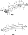
- FIG. 1 shows schematically in side view an escalator 1, which connects a first floor E1 with a second floor E2.
- the escalator 1 has a supporting structure 6 or truss 6 with two deflection areas 7, 8, between which a step belt 5 is guided circumferentially.
- the stepped belt has traction means 9, on which steps 4 are arranged.
- a handrail 3 is arranged on a balustrade 2.
- the balustrade 2 is connected at the lower end by means of a balustrade base to the supporting structure 6.
- FIG. 2 Built up in an analogous way, shows FIG. 2 schematically in side view a moving walkway 11, which also has a balustrade 12 with balustrade base and handrail 13, a supporting structure 16, and two deflection regions 17, 18 has.
- a moving walkway 11 which also has a balustrade 12 with balustrade base and handrail 13, a supporting structure 16, and two deflection regions 17, 18 has.
- the pallet band 15 has traction means 19, on which pallets 14 are arranged.
- the moving walk 11 connects for example a third floor E3 with a fourth floor E4.
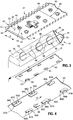
- FIGS. 3 to 5 are described together below, since in these figures the same pallet 14 or parts of this pallet 14 are shown. Consequently, for the corresponding features in the FIGS. 3 to 5 the same reference numerals used.
- FIG. 3 shows an exploded view of a portion of one of the in FIG. 2
- the pallet 14 has a partially illustrated support body 30 which is approximately tubular and whose triangular pipe cross-section extends along a width B of the pallet 14.
- the support body 30 may be made of metal, for example aluminum, brass, steel, high-alloy chromium steel, bronze, or copper, but also of plastic, in particular of glass fiber reinforced and / or carbon fiber reinforced composite materials.
- the support body 30 has a plurality of recesses 32, 33 in order to reduce its weight.
- the Recess 33 extends over the entire width of the support body 30. Due to the triangular cross section, a base 31 on the support body 30 is present, on which at least one tread element 40 can be attached.
- the tread elements 40 of steps and pallets 14 have on their tread 41 a tread pattern in the form of a series of parallel, extending from the front to the rear of the tread element 40 ribs 49.
- the ribs 49 and webs 49 extend in the intended direction of movement X (forward and backward) of the step or pallet 14.
- Each of the tread elements 40 is in its planar extent by two parallel, extending in the intended direction of movement X of the step or pallet 14 end faces 45, 46 and two to the end faces 45, 46 orthogonally arranged edge sides 47, 48 limited.
- the end faces 45, 46 and edge sides 47, 48 are provided with reference numerals only on one of the tread elements 40.
- a tread element 40 has different zones with regard to the configuration of its accessible area.
- the major part of the accessible area of the tread elements 40 is provided with the ribs 49.
- the two front ends of a pallet 14 may each have a narrow edge portion 51 without ribs 49. If the accessible area of a pallet 14 should have such edge portions 51, the tread elements 40 can be designed differently. For example, tread elements 40 with molded-on edge sections 51 and tread elements 40 without edge sections 51 can be combined with one another.
- Each of the tread elements 40 has in each case six fastening projections 43, which are formed on an underside 42 of the tread element 40.
- the fastening projection 43 may, for example, have a conical, frustoconical, cylindrical or cuboid basic shape.
- the attachment projections 43 project through openings 34 in the base.
- Each of the fastening projections 43 has a recess 44. The position of the recess 44 on the mounting projection 43 is matched to the material thickness of the support body 30, so that when placed on the base 31 tread element 40 of the mounting projection 43 and the recess 44 at least partially on the side facing away from the tread element 40 side 35 of the base 31 of the assigned Breakthrough 34 protrudes.
- a fixing element 60 is shown below the support body 30, below the support body 30, a fixing element 60 is shown.
- the fixing element 60 as in the FIG. 5 shown within the support body 30 on the opposite side 35 of the base 31 fitting, arranged.
- the fixing element 60 in the present embodiment has the same number of mounting openings 61, as all tread elements 40 of a pallet 14 together fastening projections 43 have.
- Each of the mounting apertures 61 includes an insertion portion 62 and a fixing portion 63.
- the cross section of the insertion portion 62 correlates with the cross section of the attachment projection 43 so that the attachment projection 43 can be inserted through the insertion portion 62 in the direction of its longitudinal extent.
- the cross section of the fixing region 63 correlates with the reduced cross section of the fastening projection 43 around the recess 44.
- the recesses 44 of the fastening projections 43 are aligned such that the fixing element 60 is parallel to the planar extent of the tread element 40 or to the opposite side 35 of the base 31 in the provided Displacement direction V is pushed. After insertion of the fixing element 60, the fixation regions 63 come into contact with the fastening projections 43 and thus regions of the fixing element 60 between the base 31 and the fastening projections 43 as a result of the subsequent displacement thereof.
- a positioning breakthrough 36 is further formed with a circular hole cross-section.
- a positioning projection 53 arranged on the tread element 40 fits precisely into this positioning opening 36.
- FIG. 4 shows in a three-dimensional, larger representation of a section of the in the FIG. 3 illustrated fixing element 60 with a selection of possible embodiments of mounting apertures 61.
- their reference numerals are supplemented with letters.
- the first embodiment of a mounting aperture 61A has only an insertion portion 62A and a fixing portion 63A.
- This mounting aperture 61A is not able, without further means, to bias the tread element 40 against the base 31 of the support body 30.
- the fixing element 60 exclusively Mounting apertures 61A of this first embodiment, at least one other element must be present, which generates the biasing force.
- the fixing element 60 has, for example, a spring tab 65 which protrudes against the remote side 35 of the base 31 and pushes the fixing element 60 away from the opposite side of the base 31 after assembly.
- the fixing regions 63A resting in the recesses 44 on the fastening projections 43 and thus the tread element 40 pull against the base 31.
- the second embodiment of a mounting aperture 61B has a rigid Vertex 64B in the fixation region 63B.
- the rigid V-tongue 64B is applied to a contour of the recess 44 and pulls the tread element 40 against the base 31.
- rigid splines 64B thus no spring element such as the formation of a spring tab 65 is necessary , However, such a spring tab can still be formed on the fixing and serve as a detent 65, for example, if the base 31 has a suitable Einrastaus Principleung.
- the fixing element 60 may be performed self-locking in the assembled state due to the friction conditions.
- the third embodiment of a mounting aperture 61C does not have a rigid but flexible tongue 64C.
- the elastic Veilzunge 64C is also disposed in the fixing portion 63C and can, for example, as shown, by means of bending along an angle ⁇ to the longitudinal extent of the fixing member 60 obliquely arranged bending line 66C are generated.
- the elastic Veilzunge 64C has the advantage that they can adapt to the production engineering, different installation conditions between a created by the recess 44 approach contour of the mounting projection 43 and the base 31 opposite side 35, when the fixing member 60 is moved and the mounting projection 43 passes from the insertion portion 62C in the fixing portion 63C.
- each mounting opening 61 of a fixing element 60 has at least one elastic Veilzunge 64 C, then all securing projections 43 secured therewith a pallet 14 subjected to approximately the same biasing force and thus the tread element 40 is uniformly biased over its planar extension biased against the base 31 of the support body 30, as shown in the FIG. 5 is shown.
- the fourth embodiment of a mounting aperture 61D like the embodiment described above, has an elastic or resilient Vertex 64D.
- This elastic vertex 64D is further provided with a detent 67D.
- the elastic vertex 64D with detent 67D has the same functions as the elastic vertex 64C of the third embodiment.
- a fixing element 60 may comprise all types of mounting apertures 61A, 61B, 61C, 61D. Preferably, however, all mounting apertures 61 are the same or at most two different embodiments in a fixing element 60 is formed.
- FIG. 5 shows in three-dimensional view a partial bottom view of the in FIG. 3 shown pallet 14 with already applied tread element 40 and mounted fixing 60.
- the resilient V-tongue 64C of a mounting aperture 61C of the third embodiment engages in the recess 44 of the fastening projection 43 and thereby fixes the tread element 40 prestressed against the base 31 at this point.
- the fixing element 60 is not yet fully inserted in the mounting direction V, so that a part of the fixing region 63C is still recognizable.
- the elements described above can also be used for mounting steps 4 of escalators 1.
- FIG. 6 the elements described above can also be used for mounting steps 4 of escalators 1.
- FIG. 6 shows in a sectional side view a step 4 with a tubular support body 130, which also has a base 131.
- the support body 130 is for example made of a Made of extruded aluminum.
- a step roller receptacle 180 for receiving a stepped roller 181 is arranged.
- Even at the level 4 are limited by end faces and in the width extending edge sides 147, 148 tread elements 140 with its bottom 142 on the base 131 of the support body 130 resting. These are attached to the support body 130 in an analogous manner to the pallet described above, wherein a number of fastening projections 143 are visible in the sectional representation. In deviation to those in the FIGS. 3 to 5 shown mounting projections 43, have the in the FIG.
- the fixing element 160 accordingly has mounting openings 161, the fixing areas of which engage in both recesses 144A, 144B of a fastening projection 143.
- the step 4 further comprises a setting member 190 which has lower hook projections 193 and upper fastening projections 194 disposed in the widthwise extending edge portions 191, 192.
- the upper attachment projections 194 arranged in the region of the base 131 are formed like the mounting projections 143 of the tread element 140 and protrude into the openings 134 formed in the base.
- the lower hook projections 193 arranged near the stepped roller receptacle 180 project into lower assembly openings 136 and undercut a front wall 139 of the Supporting body 130. Securing the setting element 190 by means of the fixing element 160 takes place analogously to the securing of the tread element 140.
- the setting element 190 and the tread element 140 can be placed on the support body 130.
- the tread element 140 and the setting element 190 are fixed to the support body 130 by pushing or driving in the fixing element 160 on the side 135 of the base 131 facing away from the tread element 140.
- the setting element 190 can of course also be fixedly connected to the support body 130 by welding, soldering, riveting clinching, gluing or by screwing.
- the setting element 190 likewise has ribs 198 which connect the ribs 149 arranged on the tread surface 141 of the tread element 140.
- the tubular support body may have a cross section which differs from the trapezoidal or triangular cross-sectional shape, for example by means of further folds a polygonal cross-sectional shape is created.
- tread elements with the fastening concept according to the invention can also be used in a step with a step skeleton.
- the tread elements do not necessarily have to be an aluminum casting.
- the tread elements can also be worked out of a blank or produced by means of a die as forging.
- the tread elements may consist of sheet metal parts, in particular deep-drawn sheet metal parts.
- the tread elements may be made of a glass fiber reinforced and / or carbon fiber reinforced plastic or of another composite material.
- the tread elements may at least partially be made of a natural stone such as granite or marble or of an amorphous material such as glass.
Landscapes
- Escalators And Moving Walkways (AREA)
Claims (14)
- Marche (4) d'un escalier roulant (1) ou palette (14) d'un trottoir roulant (11), comportant un corps porteur (30, 130) avec une base (31, 131), au moins un élément de fixation (60, 160) et au moins un élément formant marche (40, 140) avec une surface de marche (41, 141), le ou les éléments formant marches (40, 140) présentant sur un côté inférieur (42, 142) opposé à la surface de marche (41, 141) au moins une saillie de fixation (43, 143), et à l'état monté la ou les saillies de fixation (43, 143) dépassant par une ouverture (34, 134) formée dans la base (31, 131) et associée à cette saillie de fixation (43, 143), caractérisée en ce que la saillie de fixation (43, 143) présente au moins un creux (44, 44A, 144B) qui s'étend parallèlement à la surface de marche (41, 141) et dans lequel l'élément de fixation (60, 160) est apte à être glissé au moins en partie, de sorte qu'à l'état monté l'élément de fixation (60, 160) est disposé au moins en partie entre la base (31, 131) et la saillie de fixation (43, 143) et que l'élément formant marche (40, 140) est fixé en étant précontraint par l'élément de fixation (60, 160) contre la base (31, 131).
- Marche (4) ou palette (14) selon la revendication 1, la ou les saillies de fixation (43, 143) s'étendant perpendiculairement à la surface de marche (41, 141).
- Marche (4) ou palette (14) selon la revendication 1 ou 2, l'élément de marche (40, 140) étant limité dans son extension plane par au moins deux côtés frontaux (45, 46) parallèles qui s'étendent dans le sens de déplacement prévu (X) de la marche (4) ou de la palette (14), et par au moins deux côtés latéraux (47, 48, 147, 148) qui sont disposés perpendiculairement aux côtés frontaux (45, 46).
- Marche (4) ou palette (14) selon l'une des revendications 1 à 3, l'élément de fixation (60, 160) étant apte à glisser parallèlement à la base (31, 131).
- Marche (4) ou palette (14) selon l'une des revendications 1 à 4, toutes les saillies de fixation (43, 143) de tous les éléments formant marches (40, 140) disposés sur la base (31, 131) d'un corps portant (30, 130) étant aptes à être fixées sur ledit corps portant (30, 130) en étant précontraintes par un élément de fixation commun (60, 160) contre la base (31, 131).
- Marche (4) ou palette (14) selon l'une des revendications 1 à 5, le ou les éléments de fixation (60, 160) présentant, pour produire une force de précontrainte, au moins une languette à coin (64B, 64C, 64D).
- Marche (4) ou palette (14) selon la revendication 6, la ou les languettes à coin (64C, 64D) étant élastiques.
- Marche (4) ou palette (14) selon l'une des revendications 6 ou 7, au moins un cran (65, 67D) étant formé sur l'élément de fixation (60, 160).
- Marche (4) ou palette (14) selon l'une des revendications 1 à 8, étant précisé que sur l'élément formant marche (40, 140) est formé au moins un élément de positionnement (53) qui, quand ledit élément formant marche (40, 140) est posé, dépasse dans une ouverture de positionnement à ajustement précis (36) de la base (31, 131).
- Marche (4) ou palette (14) selon l'une des revendications 1 à 9, le corps porteur (30, 130) étant tubulaire et présentant une section transversale triangulaire ou trapézoïdale.
- Bande de palettes (15) d'un trottoir roulant (11) avec au moins un moyen de traction (19) et plusieurs palettes (14) selon l'une des revendications 1 à 10 disposées sur le moyen de traction (19).
- Bande de marches (5) d'un escalier roulant (1) avec au moins un moyen de traction (9) et plusieurs marches (4) selon l'une des revendications 1 à 10 disposées sur le moyen de traction (9).
- Trottoir roulant (11) avec une bande de palettes (15) selon la revendication 11 disposée pour circuler, ou escalier roulant (1) avec une bande de marches (5) selon la revendication 12 disposée pour circuler.
- Procédé pour moderniser un trottoir roulant (11) en remplaçant la bande de palettes existante par une bande de palettes (15) selon la revendication 11, ou un escalier roulant (1) en remplaçant la bande de marches existante par une bande de marches (5) selon la revendication 12.
Applications Claiming Priority (2)
| Application Number | Priority Date | Filing Date | Title |
|---|---|---|---|
| EP14152921 | 2014-01-28 | ||
| PCT/EP2014/076549 WO2015113680A1 (fr) | 2014-01-28 | 2014-12-04 | Palette de trottoir roulant ou marche d'escalier mécanique |
Publications (2)
| Publication Number | Publication Date |
|---|---|
| EP3099617A1 EP3099617A1 (fr) | 2016-12-07 |
| EP3099617B1 true EP3099617B1 (fr) | 2018-02-07 |
Family
ID=50000898
Family Applications (1)
| Application Number | Title | Priority Date | Filing Date |
|---|---|---|---|
| EP14808599.6A Active EP3099617B1 (fr) | 2014-01-28 | 2014-12-04 | Palette pour un trottoir roulant ou marche pour un escalier roulant |
Country Status (6)
| Country | Link |
|---|---|
| US (1) | US9617122B2 (fr) |
| EP (1) | EP3099617B1 (fr) |
| CN (1) | CN105916796B (fr) |
| BR (1) | BR112016016142A2 (fr) |
| ES (1) | ES2660480T3 (fr) |
| WO (1) | WO2015113680A1 (fr) |
Cited By (3)
| Publication number | Priority date | Publication date | Assignee | Title |
|---|---|---|---|---|
| US10793398B2 (en) | 2018-09-14 | 2020-10-06 | Otis Elevator Company | Conveyance element for a people conveyor |
| US10829346B2 (en) | 2018-01-15 | 2020-11-10 | Otis Elevator Company | Moving walkway |
| US11066275B2 (en) | 2019-01-23 | 2021-07-20 | Otis Elevator Company | Conveyance belt for a conveyor |
Families Citing this family (7)
| Publication number | Priority date | Publication date | Assignee | Title |
|---|---|---|---|---|
| EP3269675B1 (fr) * | 2016-07-15 | 2020-11-18 | Otis Elevator Company | Élément de transport pour un dispositif de transport de personnes |
| KR102399371B1 (ko) * | 2016-10-31 | 2022-05-17 | 인벤티오 아게 | 복귀 진행에서 서로 정합 가능하게 맞물리는 트레드들을 갖는 에스컬레이터 |
| EP3360838A1 (fr) * | 2017-02-09 | 2018-08-15 | Otis Elevator Company | Dispositif de transport de personnes, bande de transport et élément de transport d'un dispositif de transport de personnes |
| EP3747822B1 (fr) * | 2019-06-03 | 2024-05-01 | Otis Elevator Company | Élément de transport pour un convoyeur de personnes |
| EP3747823B1 (fr) * | 2019-06-03 | 2022-07-27 | Otis Elevator Company | Élément de transport pour un convoyeur de personnes |
| US10988348B1 (en) * | 2020-05-26 | 2021-04-27 | Otis Elevator Company | Escalator steps with strain sensors |
| JP7645708B2 (ja) * | 2021-05-13 | 2025-03-14 | 三菱電機ビルソリューションズ株式会社 | エスカレーターの踏段 |
Family Cites Families (12)
| Publication number | Priority date | Publication date | Assignee | Title |
|---|---|---|---|---|
| US5337879A (en) * | 1984-08-21 | 1994-08-16 | Inventio Ag | Tread element for moving pavement or escalator |
| JPS6312584A (ja) * | 1986-06-30 | 1988-01-19 | 三菱電機株式会社 | 乗客コンベアの案内装置 |
| JP2603031B2 (ja) | 1992-07-03 | 1997-04-23 | 三菱電機株式会社 | エスカレーターのステップ |
| NZ248336A (en) * | 1993-08-05 | 1995-11-27 | Escalator Advertising Ltd | Escalator step riser backing plate to accomodate display cover plate |
| DE19850847A1 (de) * | 1998-11-04 | 2000-05-11 | Moessner Druckguswerk Gmbh | Fahrtreppenstufe |
| DE29909808U1 (de) | 1999-06-04 | 1999-09-23 | Thyssen Fahrtreppen GmbH, 22113 Hamburg | Fahrtreppenstufe |
| JP3833049B2 (ja) | 2000-05-10 | 2006-10-11 | 株式会社日立ビルシステム | 乗客コンベアの踏段 |
| CN2644393Y (zh) * | 2003-09-10 | 2004-09-29 | 何辉淳 | 拼接式人行道踏板结构 |
| FI116563B (fi) | 2004-04-22 | 2005-12-30 | Kone Corp | Liukukäytävän tai vastaavan palettijärjestely |
| EP2017216A1 (fr) | 2007-07-16 | 2009-01-21 | Inventio Ag | Marche d'escalier roulant comprenant des inserts et dispositif de vérification des insert |
| JP4399484B2 (ja) * | 2007-08-27 | 2010-01-13 | 株式会社日立製作所 | 乗客コンベア |
| WO2009047146A1 (fr) | 2007-10-01 | 2009-04-16 | Inventio Ag | Structure de marche ou structure de palette pour des unités de marche d'un système de transport, unités de marche et système de transport |
-
2014
- 2014-12-04 US US15/114,888 patent/US9617122B2/en active Active
- 2014-12-04 CN CN201480073560.8A patent/CN105916796B/zh active Active
- 2014-12-04 BR BR112016016142A patent/BR112016016142A2/pt not_active Application Discontinuation
- 2014-12-04 WO PCT/EP2014/076549 patent/WO2015113680A1/fr not_active Ceased
- 2014-12-04 ES ES14808599.6T patent/ES2660480T3/es active Active
- 2014-12-04 EP EP14808599.6A patent/EP3099617B1/fr active Active
Cited By (3)
| Publication number | Priority date | Publication date | Assignee | Title |
|---|---|---|---|---|
| US10829346B2 (en) | 2018-01-15 | 2020-11-10 | Otis Elevator Company | Moving walkway |
| US10793398B2 (en) | 2018-09-14 | 2020-10-06 | Otis Elevator Company | Conveyance element for a people conveyor |
| US11066275B2 (en) | 2019-01-23 | 2021-07-20 | Otis Elevator Company | Conveyance belt for a conveyor |
Also Published As
| Publication number | Publication date |
|---|---|
| US20160355379A1 (en) | 2016-12-08 |
| CN105916796B (zh) | 2017-10-20 |
| CN105916796A (zh) | 2016-08-31 |
| WO2015113680A1 (fr) | 2015-08-06 |
| EP3099617A1 (fr) | 2016-12-07 |
| BR112016016142A2 (pt) | 2017-08-08 |
| ES2660480T3 (es) | 2018-03-22 |
| US9617122B2 (en) | 2017-04-11 |
Similar Documents
| Publication | Publication Date | Title |
|---|---|---|
| EP3099617B1 (fr) | Palette pour un trottoir roulant ou marche pour un escalier roulant | |
| EP3044153B1 (fr) | Palette pour un trottoir roulant ou marche pour un escalier roulant | |
| EP1900621B1 (fr) | Coussin de roulement échangeable et procédé de fabrication de coussins de roulement pour chenilles | |
| EP1294995B1 (fr) | Système de plancher comprenant un pluralité de planches de plancher identiques | |
| EP3060511B1 (fr) | Dispositif de fixation pour la fixation d'un gradin ou d'une palette à un moyen de traction | |
| DE112007001924B4 (de) | Einfach zu demontierende Fahrtreppen-Außenabdeckung | |
| DE69409284T2 (de) | Geländeraufbau und Verfahren für die Montage desselben | |
| EP2200925B1 (fr) | Structure de marche ou structure de palette pour des unités de marche d'un système de transport, unités de marche et système de transport | |
| EP3137406B1 (fr) | Système de voie pour un escalier roulant ou un trottoir roulant | |
| WO2015180964A1 (fr) | Dispositif de fixation d'une palette à un moyen de traction | |
| EP2734465B1 (fr) | Pièce structurale pourvue d'un dispositif de fixation destiné à des pièces à monter | |
| DE69704448T2 (de) | Stufenelement für Fahrtreppen oder Fahrsteige | |
| EP2309076A2 (fr) | Plateforme à encliquetage pour échafaudage | |
| EP3507229B1 (fr) | Marche d'escalier roulant ayant des pieces males | |
| EP2017216A1 (fr) | Marche d'escalier roulant comprenant des inserts et dispositif de vérification des insert | |
| EP3765685B1 (fr) | Escalier d'échafaudage comprenant des supports de marche | |
| DE69418981T2 (de) | Kammplatte für Rolltreppen oder Fahrsteige | |
| EP3842373A1 (fr) | Système de rail d'ascenseur permettant un montage facile | |
| DE60009330T2 (de) | Vorrichtung und verfahren zur befestigung eines flachelements an einem fahrzeug | |
| DE20318090U1 (de) | Gerüstboden-Sicherungs-Befestigungsbolzen | |
| EP1873340B1 (fr) | Installation de porte | |
| AT505737B1 (de) | Vorrichtung zum verbinden zweier stumpf stossender bauteile | |
| EP4263411A1 (fr) | Dispositif de fixation de rail pour des sections de rail de guidage d'un escalier roulant ou d'un trottoir roulant | |
| EP0494403B1 (fr) | Guidage pour une main coulante pour escaliers ou trottoirs roulants | |
| EP3169617B1 (fr) | Composant de revêtement pour escalier mécanique ou trottoir roulant |
Legal Events
| Date | Code | Title | Description |
|---|---|---|---|
| PUAI | Public reference made under article 153(3) epc to a published international application that has entered the european phase |
Free format text: ORIGINAL CODE: 0009012 |
|
| 17P | Request for examination filed |
Effective date: 20160621 |
|
| AK | Designated contracting states |
Kind code of ref document: A1 Designated state(s): AL AT BE BG CH CY CZ DE DK EE ES FI FR GB GR HR HU IE IS IT LI LT LU LV MC MK MT NL NO PL PT RO RS SE SI SK SM TR |
|
| AX | Request for extension of the european patent |
Extension state: BA ME |
|
| DAX | Request for extension of the european patent (deleted) | ||
| GRAP | Despatch of communication of intention to grant a patent |
Free format text: ORIGINAL CODE: EPIDOSNIGR1 |
|
| INTG | Intention to grant announced |
Effective date: 20170717 |
|
| GRAS | Grant fee paid |
Free format text: ORIGINAL CODE: EPIDOSNIGR3 |
|
| GRAA | (expected) grant |
Free format text: ORIGINAL CODE: 0009210 |
|
| AK | Designated contracting states |
Kind code of ref document: B1 Designated state(s): AL AT BE BG CH CY CZ DE DK EE ES FI FR GB GR HR HU IE IS IT LI LT LU LV MC MK MT NL NO PL PT RO RS SE SI SK SM TR |
|
| REG | Reference to a national code |
Ref country code: GB Ref legal event code: FG4D Free format text: NOT ENGLISH |
|
| REG | Reference to a national code |
Ref country code: AT Ref legal event code: REF Ref document number: 968697 Country of ref document: AT Kind code of ref document: T Effective date: 20180215 Ref country code: CH Ref legal event code: EP |
|
| REG | Reference to a national code |
Ref country code: IE Ref legal event code: FG4D Free format text: LANGUAGE OF EP DOCUMENT: GERMAN |
|
| REG | Reference to a national code |
Ref country code: DE Ref legal event code: R096 Ref document number: 502014007210 Country of ref document: DE |
|
| REG | Reference to a national code |
Ref country code: ES Ref legal event code: FG2A Ref document number: 2660480 Country of ref document: ES Kind code of ref document: T3 Effective date: 20180322 |
|
| REG | Reference to a national code |
Ref country code: NL Ref legal event code: MP Effective date: 20180207 |
|
| PG25 | Lapsed in a contracting state [announced via postgrant information from national office to epo] |
Ref country code: NO Free format text: LAPSE BECAUSE OF FAILURE TO SUBMIT A TRANSLATION OF THE DESCRIPTION OR TO PAY THE FEE WITHIN THE PRESCRIBED TIME-LIMIT Effective date: 20180507 Ref country code: CY Free format text: LAPSE BECAUSE OF FAILURE TO SUBMIT A TRANSLATION OF THE DESCRIPTION OR TO PAY THE FEE WITHIN THE PRESCRIBED TIME-LIMIT Effective date: 20180207 Ref country code: FI Free format text: LAPSE BECAUSE OF FAILURE TO SUBMIT A TRANSLATION OF THE DESCRIPTION OR TO PAY THE FEE WITHIN THE PRESCRIBED TIME-LIMIT Effective date: 20180207 Ref country code: NL Free format text: LAPSE BECAUSE OF FAILURE TO SUBMIT A TRANSLATION OF THE DESCRIPTION OR TO PAY THE FEE WITHIN THE PRESCRIBED TIME-LIMIT Effective date: 20180207 Ref country code: LT Free format text: LAPSE BECAUSE OF FAILURE TO SUBMIT A TRANSLATION OF THE DESCRIPTION OR TO PAY THE FEE WITHIN THE PRESCRIBED TIME-LIMIT Effective date: 20180207 Ref country code: HR Free format text: LAPSE BECAUSE OF FAILURE TO SUBMIT A TRANSLATION OF THE DESCRIPTION OR TO PAY THE FEE WITHIN THE PRESCRIBED TIME-LIMIT Effective date: 20180207 |
|
| PG25 | Lapsed in a contracting state [announced via postgrant information from national office to epo] |
Ref country code: GR Free format text: LAPSE BECAUSE OF FAILURE TO SUBMIT A TRANSLATION OF THE DESCRIPTION OR TO PAY THE FEE WITHIN THE PRESCRIBED TIME-LIMIT Effective date: 20180508 Ref country code: IS Free format text: LAPSE BECAUSE OF FAILURE TO SUBMIT A TRANSLATION OF THE DESCRIPTION OR TO PAY THE FEE WITHIN THE PRESCRIBED TIME-LIMIT Effective date: 20180607 Ref country code: RS Free format text: LAPSE BECAUSE OF FAILURE TO SUBMIT A TRANSLATION OF THE DESCRIPTION OR TO PAY THE FEE WITHIN THE PRESCRIBED TIME-LIMIT Effective date: 20180207 Ref country code: BG Free format text: LAPSE BECAUSE OF FAILURE TO SUBMIT A TRANSLATION OF THE DESCRIPTION OR TO PAY THE FEE WITHIN THE PRESCRIBED TIME-LIMIT Effective date: 20180507 Ref country code: SE Free format text: LAPSE BECAUSE OF FAILURE TO SUBMIT A TRANSLATION OF THE DESCRIPTION OR TO PAY THE FEE WITHIN THE PRESCRIBED TIME-LIMIT Effective date: 20180207 Ref country code: LV Free format text: LAPSE BECAUSE OF FAILURE TO SUBMIT A TRANSLATION OF THE DESCRIPTION OR TO PAY THE FEE WITHIN THE PRESCRIBED TIME-LIMIT Effective date: 20180207 Ref country code: PL Free format text: LAPSE BECAUSE OF FAILURE TO SUBMIT A TRANSLATION OF THE DESCRIPTION OR TO PAY THE FEE WITHIN THE PRESCRIBED TIME-LIMIT Effective date: 20180207 |
|
| PG25 | Lapsed in a contracting state [announced via postgrant information from national office to epo] |
Ref country code: MT Free format text: LAPSE BECAUSE OF FAILURE TO SUBMIT A TRANSLATION OF THE DESCRIPTION OR TO PAY THE FEE WITHIN THE PRESCRIBED TIME-LIMIT Effective date: 20180207 |
|
| PG25 | Lapsed in a contracting state [announced via postgrant information from national office to epo] |
Ref country code: EE Free format text: LAPSE BECAUSE OF FAILURE TO SUBMIT A TRANSLATION OF THE DESCRIPTION OR TO PAY THE FEE WITHIN THE PRESCRIBED TIME-LIMIT Effective date: 20180207 Ref country code: AL Free format text: LAPSE BECAUSE OF FAILURE TO SUBMIT A TRANSLATION OF THE DESCRIPTION OR TO PAY THE FEE WITHIN THE PRESCRIBED TIME-LIMIT Effective date: 20180207 |
|
| REG | Reference to a national code |
Ref country code: DE Ref legal event code: R097 Ref document number: 502014007210 Country of ref document: DE |
|
| PG25 | Lapsed in a contracting state [announced via postgrant information from national office to epo] |
Ref country code: SK Free format text: LAPSE BECAUSE OF FAILURE TO SUBMIT A TRANSLATION OF THE DESCRIPTION OR TO PAY THE FEE WITHIN THE PRESCRIBED TIME-LIMIT Effective date: 20180207 Ref country code: SM Free format text: LAPSE BECAUSE OF FAILURE TO SUBMIT A TRANSLATION OF THE DESCRIPTION OR TO PAY THE FEE WITHIN THE PRESCRIBED TIME-LIMIT Effective date: 20180207 Ref country code: DK Free format text: LAPSE BECAUSE OF FAILURE TO SUBMIT A TRANSLATION OF THE DESCRIPTION OR TO PAY THE FEE WITHIN THE PRESCRIBED TIME-LIMIT Effective date: 20180207 Ref country code: CZ Free format text: LAPSE BECAUSE OF FAILURE TO SUBMIT A TRANSLATION OF THE DESCRIPTION OR TO PAY THE FEE WITHIN THE PRESCRIBED TIME-LIMIT Effective date: 20180207 |
|
| PLBE | No opposition filed within time limit |
Free format text: ORIGINAL CODE: 0009261 |
|
| STAA | Information on the status of an ep patent application or granted ep patent |
Free format text: STATUS: NO OPPOSITION FILED WITHIN TIME LIMIT |
|
| 26N | No opposition filed |
Effective date: 20181108 |
|
| PG25 | Lapsed in a contracting state [announced via postgrant information from national office to epo] |
Ref country code: SI Free format text: LAPSE BECAUSE OF FAILURE TO SUBMIT A TRANSLATION OF THE DESCRIPTION OR TO PAY THE FEE WITHIN THE PRESCRIBED TIME-LIMIT Effective date: 20180207 |
|
| PGFP | Annual fee paid to national office [announced via postgrant information from national office to epo] |
Ref country code: ES Payment date: 20181218 Year of fee payment: 9 |
|
| PG25 | Lapsed in a contracting state [announced via postgrant information from national office to epo] |
Ref country code: LU Free format text: LAPSE BECAUSE OF NON-PAYMENT OF DUE FEES Effective date: 20181204 Ref country code: MC Free format text: LAPSE BECAUSE OF FAILURE TO SUBMIT A TRANSLATION OF THE DESCRIPTION OR TO PAY THE FEE WITHIN THE PRESCRIBED TIME-LIMIT Effective date: 20180207 |
|
| REG | Reference to a national code |
Ref country code: IE Ref legal event code: MM4A |
|
| REG | Reference to a national code |
Ref country code: BE Ref legal event code: MM Effective date: 20181231 |
|
| PG25 | Lapsed in a contracting state [announced via postgrant information from national office to epo] |
Ref country code: IE Free format text: LAPSE BECAUSE OF NON-PAYMENT OF DUE FEES Effective date: 20181204 |
|
| PG25 | Lapsed in a contracting state [announced via postgrant information from national office to epo] |
Ref country code: BE Free format text: LAPSE BECAUSE OF NON-PAYMENT OF DUE FEES Effective date: 20181231 |
|
| PG25 | Lapsed in a contracting state [announced via postgrant information from national office to epo] |
Ref country code: TR Free format text: LAPSE BECAUSE OF FAILURE TO SUBMIT A TRANSLATION OF THE DESCRIPTION OR TO PAY THE FEE WITHIN THE PRESCRIBED TIME-LIMIT Effective date: 20180207 |
|
| PG25 | Lapsed in a contracting state [announced via postgrant information from national office to epo] |
Ref country code: PT Free format text: LAPSE BECAUSE OF FAILURE TO SUBMIT A TRANSLATION OF THE DESCRIPTION OR TO PAY THE FEE WITHIN THE PRESCRIBED TIME-LIMIT Effective date: 20180207 |
|
| PG25 | Lapsed in a contracting state [announced via postgrant information from national office to epo] |
Ref country code: MK Free format text: LAPSE BECAUSE OF NON-PAYMENT OF DUE FEES Effective date: 20180207 Ref country code: RO Free format text: LAPSE BECAUSE OF FAILURE TO SUBMIT A TRANSLATION OF THE DESCRIPTION OR TO PAY THE FEE WITHIN THE PRESCRIBED TIME-LIMIT Effective date: 20180207 Ref country code: HU Free format text: LAPSE BECAUSE OF FAILURE TO SUBMIT A TRANSLATION OF THE DESCRIPTION OR TO PAY THE FEE WITHIN THE PRESCRIBED TIME-LIMIT; INVALID AB INITIO Effective date: 20141204 |
|
| GBPC | Gb: european patent ceased through non-payment of renewal fee |
Effective date: 20191204 |
|
| PG25 | Lapsed in a contracting state [announced via postgrant information from national office to epo] |
Ref country code: GB Free format text: LAPSE BECAUSE OF NON-PAYMENT OF DUE FEES Effective date: 20191204 |
|
| PGFP | Annual fee paid to national office [announced via postgrant information from national office to epo] |
Ref country code: FR Payment date: 20201229 Year of fee payment: 7 Ref country code: CH Payment date: 20201222 Year of fee payment: 7 |
|
| REG | Reference to a national code |
Ref country code: AT Ref legal event code: MM01 Ref document number: 968697 Country of ref document: AT Kind code of ref document: T Effective date: 20191204 |
|
| PGFP | Annual fee paid to national office [announced via postgrant information from national office to epo] |
Ref country code: IT Payment date: 20201221 Year of fee payment: 7 |
|
| PG25 | Lapsed in a contracting state [announced via postgrant information from national office to epo] |
Ref country code: AT Free format text: LAPSE BECAUSE OF NON-PAYMENT OF DUE FEES Effective date: 20191204 |
|
| REG | Reference to a national code |
Ref country code: CH Ref legal event code: PL |
|
| PG25 | Lapsed in a contracting state [announced via postgrant information from national office to epo] |
Ref country code: FR Free format text: LAPSE BECAUSE OF NON-PAYMENT OF DUE FEES Effective date: 20211231 |
|
| PG25 | Lapsed in a contracting state [announced via postgrant information from national office to epo] |
Ref country code: LI Free format text: LAPSE BECAUSE OF NON-PAYMENT OF DUE FEES Effective date: 20211231 Ref country code: CH Free format text: LAPSE BECAUSE OF NON-PAYMENT OF DUE FEES Effective date: 20211231 |
|
| PG25 | Lapsed in a contracting state [announced via postgrant information from national office to epo] |
Ref country code: IT Free format text: LAPSE BECAUSE OF NON-PAYMENT OF DUE FEES Effective date: 20211204 |
|
| PGFP | Annual fee paid to national office [announced via postgrant information from national office to epo] |
Ref country code: ES Payment date: 20230118 Year of fee payment: 9 |
|
| REG | Reference to a national code |
Ref country code: ES Ref legal event code: FD2A Effective date: 20250128 |
|
| PG25 | Lapsed in a contracting state [announced via postgrant information from national office to epo] |
Ref country code: ES Free format text: LAPSE BECAUSE OF NON-PAYMENT OF DUE FEES Effective date: 20231205 |
|
| PGFP | Annual fee paid to national office [announced via postgrant information from national office to epo] |
Ref country code: DE Payment date: 20251229 Year of fee payment: 12 |