EP3100015B1 - Procédé permettant de faire fonctionner un transducteur de mesure de pression et transducteur de mesure de pression - Google Patents
Procédé permettant de faire fonctionner un transducteur de mesure de pression et transducteur de mesure de pression Download PDFInfo
- Publication number
- EP3100015B1 EP3100015B1 EP14733223.3A EP14733223A EP3100015B1 EP 3100015 B1 EP3100015 B1 EP 3100015B1 EP 14733223 A EP14733223 A EP 14733223A EP 3100015 B1 EP3100015 B1 EP 3100015B1
- Authority
- EP
- European Patent Office
- Prior art keywords
- capacitor
- pressure
- capacitance
- cavity
- measurement membrane
- Prior art date
- Legal status (The legal status is an assumption and is not a legal conclusion. Google has not performed a legal analysis and makes no representation as to the accuracy of the status listed.)
- Not-in-force
Links
Images

Classifications
-
- G—PHYSICS
- G01—MEASURING; TESTING
- G01L—MEASURING FORCE, STRESS, TORQUE, WORK, MECHANICAL POWER, MECHANICAL EFFICIENCY, OR FLUID PRESSURE
- G01L27/00—Testing or calibrating of apparatus for measuring fluid pressure
- G01L27/007—Malfunction diagnosis, i.e. diagnosing a sensor defect
-
- G—PHYSICS
- G01—MEASURING; TESTING
- G01L—MEASURING FORCE, STRESS, TORQUE, WORK, MECHANICAL POWER, MECHANICAL EFFICIENCY, OR FLUID PRESSURE
- G01L9/00—Measuring steady of quasi-steady pressure of fluid or fluent solid material by electric or magnetic pressure-sensitive elements; Transmitting or indicating the displacement of mechanical pressure-sensitive elements, used to measure the steady or quasi-steady pressure of a fluid or fluent solid material, by electric or magnetic means
- G01L9/0041—Transmitting or indicating the displacement of flexible diaphragms
- G01L9/0072—Transmitting or indicating the displacement of flexible diaphragms using variations in capacitance
-
- G—PHYSICS
- G01—MEASURING; TESTING
- G01M—TESTING STATIC OR DYNAMIC BALANCE OF MACHINES OR STRUCTURES; TESTING OF STRUCTURES OR APPARATUS, NOT OTHERWISE PROVIDED FOR
- G01M3/00—Investigating fluid-tightness of structures
- G01M3/40—Investigating fluid-tightness of structures by using electric means, e.g. by observing electric discharges
Definitions
- the invention relates to a method for operating a pressure transducer with a pressure sensor having a deflectable depending on a media pressure measuring diaphragm on a base body, between which a cavity is enclosed with a reference pressure, according to the preamble of claim 1 and a pressure transmitter for process instrumentation according to the preamble of claim 8.
- a variety of field devices are used for process instrumentation to control processes.
- Transmitters are used to record process variables, such as temperature, pressure, flow rate, level, density or gas concentration of a medium.
- the process flow can be influenced as a function of detected process variables in accordance with a strategy predetermined, for example, by a control station.
- the invention relates in particular in the field of pressure measurement field devices with a measuring cell, which can be assigned to the class of so-called "dry" pressure measuring cells.
- a measuring cell which can be assigned to the class of so-called "dry" pressure measuring cells.
- dry pressure measuring cells there is no oil filling, which transfers the pressure of a process medium to a small and sensitive pressure sensor, which has, for example, a silicon membrane.
- the pressure sensor has a membrane in contact with the medium, which can be deflected as a function of a medium pressure to be measured.
- WO 2013/004438 A1 is a dry pressure cell with capacitive detection of the deflection of the diaphragm known.
- Core of the measuring cell forms there a ceramic pressure sensor, which has a flexible measuring membrane and a base body, between which a cavity is enclosed with a reference pressure.
- the deflection of the measuring diaphragm is thus dependent on a media pressure, the media side of the measuring diaphragm, and the reference pressure in the cavity.
- a first capacitor has as a measuring capacitor a measuring electrode which is arranged on the inner wall of the cavity in the central region of the base body, and wherein a second capacitor as a reference capacitor has a reference electrode, which is in the edge region of the main body is located on the inner wall of the cavity.
- a metallization which is applied to the side of the measuring membrane, which faces the cavity, forms a common counter electrode for the two capacitors. It is described that the capacitance of the reference capacitor is dependent on the capacitance of the measuring capacitor in the error-free case according to an empirically learned function.
- the invention has for its object to provide a method for operating a pressure transducer and a pressure transducer, which make it possible to early detection of changes in the filling of the cavity of the pressure sensor, in particular by penetrating process medium, ie, before a failure of the pressure transmitter has taken place.
- Claim 8 describes a pressure transmitter for carrying out the method, a computer program in claim 9 and a computer program product in claim 10.
- the new approach is thus taken that the capacity of a diagnostic capacitor is evaluated for diagnosis, which is formed by the located on the same surface electrodes of the measuring and the reference capacitor.
- the new diagnosis based on the evaluation of the capacity of the diagnostic capacitor can be performed alternatively to a diagnosis based on an evaluation of the capacitances of the measuring and / or reference capacitor or in combination with this.
- the capacity of the diagnostic capacitor largely independent of the voltage applied to each pressure transducer and the medium-adjusting itself Bend line of the measuring diaphragm is. Since at least a portion of the electric field between the two electrodes of the diagnostic capacitor senses the cavity of the pressure sensor, its capacitance is significantly affected by the dielectric conductivity of the materials in the cavity.
- the new diagnosis of the pressure transmitter therefore permits a reliable statement about the state of filling of the cavity, in particular about changes in the relative humidity prevailing in the cavity and / or via process medium penetrating into the cavity, whereby the dielectric conductivity of the Filling is changed.
- a defect in particular a crack or break of the measuring membrane or a crack at the joint between the measuring membrane and the base body.
- a prognosis is possible as to when a total failure of the pressure transducer must be expected.
- An accurate determination of the current capacity of the diagnostic capacitor is made possible, for example, when using the known AD7746 ADC / Digital Converter (ADC) of Analog Devices by switching to a diagnostic mode in which the two electrodes of the diagnostic capacitor to the terminals EXT or CIN2 and the common counter electrode are switched to the terminal GND. It is thereby achieved that the capacitances between the electrodes of the diagnosis capacitor and the counterelectrode, which correspond to the measuring capacitor and the reference capacitor, are treated and compensated for in the measurement of the capacity of the diagnosis capacitor in the diagnostic mode, such as screening capacities. This also has the advantage that no additional electrodes for the realization of the diagnostic capacitor are needed. The invention is therefore advantageously not associated with an increase in the hardware cost of the pressure transmitter.
- ADC Analog Converter
- the comparatively small capacity of the diagnostic capacitor can be precisely measured.
- the capacitance / digital converter can be connected in a known manner.
- the capacity of the diagnosis capacitor can be regarded as a parasitic capacitance or stray capacitance which, due to its comparatively small size, has hardly any influence on the measurement result.
- the reaction speed and sensitivity of the diagnosis capacitor with respect to the relative humidity in the cavity can therefore be advantageously increased by a polymer dielectric, in particular by a Kapton foil, which is arranged between the electrodes of the diagnosis capacitor. This additional dielectric is thus arranged such that at least part of the electrical field of the diagnostic capacitor comes to lie in this.
- a Kapton film has the advantage that it has a hysteresis-poor characteristic of their dielectric conductivity of the relative humidity.
- the determined capacitance of the diagnostic capacitor is compared with a first predetermined threshold and in case of exceeding the first threshold, generates a warning signal and output by the pressure transmitter, by which the presence of a critical condition of the pressure sensor as a precursor to a possible later subsequent malfunction is shown.
- the capacity of the diagnosis capacitor can additionally be compared with a second predetermined threshold value, wherein in the case of exceeding the second threshold value, an alarm signal is generated and output, by which a malfunction occurring in the foreseeable future is displayed. This has the advantage of giving a reliable indication of an impending failure. Before a costly plant downtime can thus be initiated in time maintenance.
- the diagnosis can advantageously be further developed in such a way that depending on the capacity of the diagnosis capacitor in the good condition, which is determined during commissioning or as a parameter, depending on a given dielectric conductivity of a medium penetrating into the cavity, the two threshold values and the distance of the Time points of their passing an estimated value for a period until the occurrence of the impending malfunction is determined and output. Namely, it can be advantageously judged on the basis of this estimated value whether a repair is already required in the next maintenance cycle. Maintenance measures are thus easier to plan.
- the warning signal for indicating any required maintenance is issued directly on a service device, so that a service technician already receives on-site suitable instructions for performing the maintenance.
- the method is preferably implemented in software or in a combination of software / hardware, so that the invention also provides a computer program with computer executable program code instructions for implementing the above sketched and described below.
- the invention also relates to a computer program product, in particular a data carrier or a storage medium, with a computer program executable by a computer.
- a computer program is preferably part of a control and evaluation electronics of the pressure transmitter or is kept in a memory of the electronics or can be loaded into this memory, so that during operation of the pressure transmitter whose diagnosis is carried out automatically by the method.
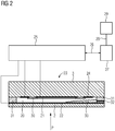
- the central component of the substantially rotationally symmetrical measuring cell 1 is a disk-shaped pressure sensor 23, which has a sensor membrane 2 and a base body 3. Between sensor membrane 2 and main body 3, a cavity 20 is included, the structure of which later FIG. 2 is explained in more detail.
- a reference pressure which, for example, corresponds to vacuum in the case of an absolute pressure transducer, and to a pressure transducer for gauge pressure, for example, to the ambient pressure.
- the respective deflection of the measuring diaphragm 2 which is dependent on the applied pressure P and the reference pressure prevailing in the cavity 20, is detected capacitively by means of the pressure sensor 23.
- Process connection 4 which also forms a first housing part of the pressure transmitter in the embodiment shown and in a groove 5 carries an elastic sealing ring 6, which is designed here as an O-ring.
- a hollow cylindrical spacer ring 10 is inserted, which is deflectable in the radial direction and thus reduces the occurrence of radial stresses in the pressure sensor 23 with temperature fluctuations.
- the sealing ring 6 is first inserted into the groove and is there due to the dovetail groove shape reliably prevented from falling out. Subsequently, the pressure sensor 23 and the spacer ring 10 are inserted. In order to generate the axial clamping force required for mounting the pressure sensor 23, the second housing part 7, which at the same time constitutes the rear support ring, is then placed and pressed against the first housing part 4. In this case, the sealing ring 6 is compressed such that a gap 12 between the sealing ring 6 surrounding surface of the first housing part 4 and the process medium facing side of the pressure sensor 23 remains.
- the two compressed housing parts 4 and 7, which are rotationally symmetrical, are rotated about their common axis and welded together at their circular joint by a radial weld 13.
- Usual pressure sensors 3 have a diameter of about 32 mm. Depending on the pressure measuring range, the thickness of the measuring diaphragm 2 is between approx. 0.5 mm and approx. 2 mm. The cavity 20 has a height of about 0.03 mm. In case of overload, the measuring diaphragm 2 is deformed in the central region by this amount and applies itself to the base body 3. In the case of impact-like pressure loading, in the area of high material tension, in particular occur in the region of the joint between measuring diaphragm 2 and body 3, irreversible overloads or damage.
- the process medium passes the sealing ring 6 due to diffusion or leaks and reaches the peripheral region of the pressure sensor 23, this can also enter the cavity 20 and thus falsify the measurement result of the pressure transducer if, for example, a damage has occurred in the form of a gap in the glass frit.
- a first capacitor which is referred to in the present application as a measuring capacitor, is formed by a first electrode 21, also referred to as a measuring electrode, and a counter-electrode 22.
- a second capacitor referred to as a reference capacitor, has an electrode 24, which is arranged essentially circularly in the edge region, also referred to as reference electrode, and the same counterelectrode 22.
- the counter electrode 22 common to both capacitors is formed by metallization on the side of the measuring diaphragm 2 facing the cavity 20.
- the respective capacitances of the measuring and reference capacitor are detected by a control and evaluation device 25 and converted into a measured value of the pressure P, which is transmitted via an interface 26 to a higher-level controller 27 in a process plant (not shown).
- the measured value of the pressure can also be output to a service device 29 via an interface 28, for example a W-LAN, so that a service employee in the system can read off the pressure value directly at the field device, without that the field device itself must be provided with a display field.
- the control and evaluation device 25 changes to a diagnostic mode in which the wiring of an AD7746 CDC of Analog Devices is changed so that the capacity of a diagnostic capacitor, by the measuring electrode 21 and the reference electrode 24, which the same surface on the inner wall of the cavity 20, recorded and evaluated for diagnosis of the pressure transmitter.
- the capacitances of the measuring capacitor and of the reference capacitor which are larger by about a factor of 100, are compensated as shield capacitances by the CDC.
- the diagnostic mode even smaller changes in the permittivity of the mixture located in the cavity 20, in relative pressure sensors, for example due to a change in the relative humidity, detected and their influence on the measurement of the pressure P can be compensated. This can be done, for example, on the basis of previously empirically determined characteristic curves which describe the dependencies of the capacities of the measuring and reference condensers on the relative humidity prevailing in the cavity 20.
- the value of the relative humidity detected in the cavity 20 may also be output on the display of the service device 29 so that a service technician can compare it with a value of the relative humidity that he has detected with a separate sensor in the environment.
- annular polymer dielectric 30 is arranged in the cavity 20, which partially covers the measuring electrode 21 arranged in the middle region and the annular reference electrode 24 arranged in the edge region.
- a polymer dielectric 30 is advantageously a Kapton foil, which is in its characteristic, which is the dependence of the dielectric Conductivity of the relative humidity describes, characterized by a particularly low hysteresis.
- the polymer dielectric can be arranged between or under the two electrodes.
- a subsequent introduction of the polymer dielectric through an opening in the base body in a recess provided for receiving the polymer dielectric recess of the base body advantageous, the introduction is advantageous only after the base body already using high temperature by fusing the glass frit with the Measuring membrane was connected.
- Areas of the pressure sensor 23 which are exposed to particularly high mechanical stresses at the pressure P applied to the measuring diaphragm 2 are the edge region of the measuring diaphragm 2 and a so-called glass frit 31 located at the joint of the measuring diaphragm 2 and the base body 3.
- Glass solders which are usually used for the production of the Glass frit 31 are used tend to crack under thermal and / or mechanical stress.
- process medium 33 which previously leaked the seal 6 (FIG. FIG. 1 ) has penetrated into the cavity 20 and there, for example, wet a part of the counter electrode 22.
- the dielectric conductivity of the penetrating medium 33 is usually higher than that of the filling present in the cavity 20 in the faultless state.
- the pressure transmitter will continue to function.
- the ascertained capacity of the diagnosis capacitor is compared with a first, preferably in dependence of the respective process medium threshold value. In case of exceeding the first threshold value is determined by the Control and evaluation device 25 generates a warning signal and output via the interface 26 as a warning message to the higher-level control 27, by which the presence of a critical state of the pressure sensor 23 is displayed as a precursor to a possibly following malfunction.
- the warning message can be displayed on a service device 29 for the purpose of informing a service technician about the critical state of the pressure transmitter, before it fails.
- the output value of the applied pressure P is corrected by the control and evaluation device 25 to compensate for the influence of a changing permittivity of the substance mixture in the cavity 20.
- the capacity of the diagnosis capacitor is compared with a second threshold value, which is preferably predetermined as a function of the respective process medium and, when it is exceeded, an impending malfunction is indicated by an alarm signal. For example, by issuing the alarm signal on the service device 29, timely maintenance work can be initiated before a costly plant shutdown occurs.
- the second threshold value is preferably chosen such that, for example, with a constant size of the crack 32, at least a limited function of the pressure transducer can be maintained for a foreseeable period of time.
- the estimated value for the remaining period until the expected occurrence of the functional failure can be determined as a function of a predetermined value of the capacitance of the diagnosis capacitor in the good condition, the known dielectric conductivity of the process medium 33 entering the cavity 20, the two predetermined threshold values and the interval of the times of their exceeding and spent.
Landscapes
- Physics & Mathematics (AREA)
- General Physics & Mathematics (AREA)
- Health & Medical Sciences (AREA)
- Chemical & Material Sciences (AREA)
- Engineering & Computer Science (AREA)
- Analytical Chemistry (AREA)
- Biomedical Technology (AREA)
- Measuring Fluid Pressure (AREA)
Claims (10)
- Procédé pour faire fonctionner un transducteur de mesure de pression ayant un capteur (23) de pression,
dans lequel le capteur (23) de pression a une membrane (2) de mesure souple et un corps (3) de base, entre lesquels est enclose une cavité (20) ayant une pression de référence,
dans lequel une excursion de la membrane (2) de mesure dépend d'une pression (P) d'un milieu, qui s'applique du côté du milieu à la membrane (2) de mesure, et de la pression de référence, dans lequel pour détecter une excursion de la membrane (2) de mesure, il est prévu au moins un premier condensateur, qui a deux électrodes disposées dans la partie médiane de la membrane (2) de mesure ou du corps (3) de base, et qui a une distance entre électrodes (21, 22) variable en fonction de l'excursion, et
dans lequel il est prévu au moins un deuxième condensateur, qui a deux électrodes (22, 24) disposées dans la partie de bord de la membrane (2) de mesure ou du corps (3) de base, caractérisé
en ce que l'on détermine la capacité d'un condensateur de diagnostic, formé par une électrode (21) du premier condensateur et par une électrode (24), disposée sur la même surface, du deuxième condensateur et on l'exploite pour le diagnostic du transducteur de mesure de pression. - Procédé suivant la revendication 1, caractérisé en ce que, pour compenser l'influence de la permitivité du milieu se trouvant dans la cavité, on prend en compte la capacité déterminée du condensateur de diagnostic dans le calcul d'une valeur de mesure de la pression (P) du milieu.
- Procédé suivant la revendication 2, caractérisé en ce qu'un diélectrique (30) polymère est disposé entre les électrodes (21, 24) du condensateur de diagnostic pour augmenter la sensibilité à l'humidité.
- Procédé suivant l'une des revendications précédentes, caractérisé en ce que l'on compare la capacité déterminée du condensateur de diagnostic à une première valeur de seuil déterminée à l'avance et en ce que, si l'on constate un dépassement de la première valeur de seuil, on produit et on émet un signal d'avertissement, par lequel la présence d'un état critique du capteur (23) de pression est indiqué comme précurseur d'une perturbation du fonctionnement à venir éventuelle.
- Procédé suivant la revendication 4, caractérisé en ce que, si l'on constate un dépassement de la première valeur de seuil, on compare en outre la capacité du condensateur de diagnostic à une deuxième valeur de seuil déterminée à l'avance et en ce que, si l'on constate un dépassement également de la deuxième valeur de seuil, on produit et on émet un signal d'avertissement, par lequel une perturbation en cours du fonctionnement est indiquée.
- Procédé suivant la revendication 5, caractérisé en ce qu'en fonction d'une valeur donnée à l'avance de la capacité du condensateur de diagnostic, en bon état, d'une conductivité diélectrique donnée à l'avance d'un milieu (33) introduit dans la cavité (20), des deux valeurs de seuil et de la distance entre les instants de leur dépassement, on détermine et on émet une valeur d'estimation d'une durée jusqu'à l'apparition de la perturbation du fonctionnement.
- Procédé suivant l'une des revendications 4 à 6, caractérisé en ce que l'on émet le signal d'avertissement pour indiquer des mesures d'entretien, éventuellement nécessaires, vers un appareil (29) de service.
- Transduction de mesure de pression comprenant un capteur (23) de pression,
dans lequel le capteur (23) de pression a une membrane (2) de mesure souple et un corps (3) de base, entre lesquels est enclose une cavité (20) ayant une pression de référence,
dans lequel une excursion de la membrane (2) de mesure dépend d'une pression (P) d'un milieu, qui s'applique du côté du milieu à la membrane (2) de mesure, et de la pression de référence,
dans lequel pour détecter une excursion de la membrane (2) de mesure, il est prévu au moins un premier condensateur, qui a deux électrodes disposées dans la partie médiane de la membrane (2) de mesure ou du corps (3) de base, et qui a une distance entre électrode (21, 22) variable en fonction de l'excursion, et
dans lequel il est prévu au moins un deuxième condensateur, qui a deux électrodes (22, 24) disposées dans la partie de bord de la membrane (2) de mesure ou du corps (3) de base, et
comprenant un dispositif (25) de commande et d'exploitation pour détecter la capacité au moins du premier condensateur ainsi que pour déterminer et émettre une valeur de mesure de la pression (P) du milieu en fonction de la capacité détectée, caractérisé
en ce que le dispositif (25) de commande et d'exploitation est constitué en outre pour déterminer la capacité d'un condensateur de diagnostic formé par une électrode (21) du premier condensateur et une électrode (24) disposée sur la même surface du deuxième condensateur et pour l'exploiter pour le diagnostic du transducteur de mesure. - Programme d'ordinateur comprenant des instructions de code de programme pouvant être exécutées sur un ordinateur pour la mise en oeuvre du procédé suivant l'une des revendications 1 à 7, lorsque le programme d'ordinateur est réalisé sur un ordinateur.
- Produit de programme d'ordinateur, notamment support de données ou support de mémoire, comprenant un programme d'ordinateur pouvant être réalisé suivant sur un ordinateur suivant la revendication 9.
Applications Claiming Priority (2)
| Application Number | Priority Date | Filing Date | Title |
|---|---|---|---|
| DE102014201529.4A DE102014201529A1 (de) | 2014-01-28 | 2014-01-28 | Verfahren zum Betreiben eines Druckmessumformers sowie Druckmessumformer |
| PCT/EP2014/063791 WO2015113654A1 (fr) | 2014-01-28 | 2014-06-30 | Procédé permettant de faire fonctionner un transducteur de mesure de pression et transducteur de mesure de pression |
Publications (2)
| Publication Number | Publication Date |
|---|---|
| EP3100015A1 EP3100015A1 (fr) | 2016-12-07 |
| EP3100015B1 true EP3100015B1 (fr) | 2018-04-04 |
Family
ID=51022340
Family Applications (1)
| Application Number | Title | Priority Date | Filing Date |
|---|---|---|---|
| EP14733223.3A Not-in-force EP3100015B1 (fr) | 2014-01-28 | 2014-06-30 | Procédé permettant de faire fonctionner un transducteur de mesure de pression et transducteur de mesure de pression |
Country Status (5)
| Country | Link |
|---|---|
| US (1) | US10048156B2 (fr) |
| EP (1) | EP3100015B1 (fr) |
| CN (1) | CN105829850B (fr) |
| DE (1) | DE102014201529A1 (fr) |
| WO (1) | WO2015113654A1 (fr) |
Families Citing this family (20)
| Publication number | Priority date | Publication date | Assignee | Title |
|---|---|---|---|---|
| JP6108584B1 (ja) * | 2016-06-09 | 2017-04-05 | 株式会社トライフォース・マネジメント | 力覚センサ |
| DE102017212875A1 (de) * | 2017-07-26 | 2019-01-31 | Robert Bosch Gmbh | Mikromechanische Vorrichtung und Verfahren zur Herstellung einer mikromechanischen Vorrichtung |
| CN107562269B (zh) * | 2017-08-28 | 2020-04-17 | 京东方科技集团股份有限公司 | 压力触控结构和显示装置 |
| DE102018114077B4 (de) * | 2018-06-13 | 2020-02-13 | Danfoss A/S | Drucksensoranordnung |
| DE102018118646B3 (de) | 2018-08-01 | 2019-11-07 | Ifm Electronic Gmbh | Verfahren zur Funktionsüberwachung einer Druckmesszelle eines kapazitiven Drucksensors |
| DE102018118645B3 (de) * | 2018-08-01 | 2019-11-07 | Ifm Electronic Gmbh | Verfahren zur Funktionsüberwachung einer Druckmesszelle eines kapazitiven Drucksensors |
| US10942212B2 (en) | 2018-12-05 | 2021-03-09 | Psemi Corporation | System and method for testing radio frequency switches |
| US11054328B2 (en) * | 2019-03-06 | 2021-07-06 | Psemi Corporation | Parasitic insensitive sampling in sensors |
| DE102019205347B4 (de) * | 2019-04-12 | 2022-05-12 | Robert Bosch Gmbh | Mikromechanisches Bauteil für eine kapazitive Sensorvorrichtung |
| EP3786590A1 (fr) * | 2019-08-29 | 2021-03-03 | Siemens Aktiengesellschaft | Élément capteur et dispositif de détection de paramètres de processus dans une installation de frittage |
| DE102019129264B4 (de) | 2019-10-30 | 2021-07-15 | Ifm Electronic Gmbh | Verfahren zur Funktionsüberwachung einer kapazitiven Druckmesszelle |
| DE102020119655B4 (de) * | 2020-07-24 | 2022-11-03 | Core Sensing Gmbh | Hohlkörper mit einem zylinderförmigen Innenraumabschnitt und einer Messeinrichtung zur Anordnung in dem Hohlkörper |
| DE102020122128B3 (de) * | 2020-08-25 | 2021-11-04 | Ifm Electronic Gmbh | Verfahren zur Funktionsüberwachung einer kapazitiven Druckmesszelle |
| DE102020214581A1 (de) * | 2020-11-19 | 2022-05-19 | Robert Bosch Gesellschaft mit beschränkter Haftung | Sensor zur Erfassung mindestens einer Eigenschaft eines fluiden Mediums in mindestens einem Messraum |
| CN114544065B (zh) * | 2022-04-21 | 2022-07-15 | 季华实验室 | 电容薄膜规、压力测量方法、系统、电子设备及存储介质 |
| DE102022116708A1 (de) * | 2022-07-05 | 2024-01-11 | Vega Grieshaber Kg | Messanordnung und Verfahren zum Betreiben einer Messanordnung |
| DE102022120883B3 (de) | 2022-08-18 | 2023-08-03 | Ifm Electronic Gmbh | Verfahren zur Funktionsüberwachung einer kapazitiven Druckmesszelle |
| DE102023119692A1 (de) * | 2023-07-25 | 2025-01-30 | Endress+Hauser SE+Co. KG | Druckmessaufnehmer zur Bestimmung eines ersten Drucks eines Prozessmediums |
| US12506456B2 (en) * | 2023-08-24 | 2025-12-23 | Invensense, Inc. | Dynamic capacitance-to-volvage offset cancellation |
| DE102024125180A1 (de) * | 2024-09-03 | 2026-03-19 | Vega Grieshaber Kg | Verfahren zur Kompensation von Dichtungseinflüssen auf einen Messwert und Feldgerät |
Family Cites Families (15)
| Publication number | Priority date | Publication date | Assignee | Title |
|---|---|---|---|---|
| JPS6151535A (ja) * | 1984-08-22 | 1986-03-14 | Sharp Corp | 圧力センサ |
| FI93580C (fi) | 1993-10-08 | 1995-04-25 | Vaisala Oy | Menetelmä ja laitteisto epäsymmetrisen paine-eroanturin takaisinkytkemiseksi |
| CN1123764C (zh) | 2000-07-15 | 2003-10-08 | 山东省硅酸盐研究设计院 | 陶瓷压力传感器及差压传感器 |
| DE10235046A1 (de) | 2002-07-31 | 2004-02-12 | Endress + Hauser Gmbh + Co. Kg | Kapazitiver Drucksensor |
| DE20219732U1 (de) | 2002-12-18 | 2003-03-06 | Dbt Autom Gmbh | Druckaufnehmer für die Messung hydraulischer Drücke |
| US7026645B2 (en) | 2003-10-15 | 2006-04-11 | Delphi Technologies, Inc. | Leak detection method and micro-machined device assembly |
| KR20060094326A (ko) | 2005-02-24 | 2006-08-29 | 삼성전자주식회사 | 압력 측정 장치 및 이의 동작 상태 검사 방법 |
| US7308830B2 (en) * | 2006-01-26 | 2007-12-18 | Rosemount Inc. | Pressure sensor fault detection |
| US8258450B1 (en) * | 2008-06-26 | 2012-09-04 | University Of South Florida | Physical and chemical integrated flow imaging device |
| DE102009002662B4 (de) * | 2009-04-27 | 2022-11-24 | Ifm Electronic Gmbh | Kapazitiver Drucksensor als Kombinationssensor zur Erfassung weiterer Messgrößen |
| US8429978B2 (en) * | 2010-03-30 | 2013-04-30 | Rosemount Inc. | Resonant frequency based pressure sensor |
| DE102010062622A1 (de) * | 2010-12-08 | 2012-06-14 | Ifm Electronic Gmbh | Verfahren zur Selbstüberwachung einer keramischen Druckmesszelle eines kapazitiven Drucksensors und eine Auswerteschaltung zur Durchführung des Verfahrens |
| EP2520917A1 (fr) | 2011-05-04 | 2012-11-07 | Nxp B.V. | Capteur de pression capacitif MEMS, procédé de fonctionnement et procédé de fabrication |
| DE102011078557A1 (de) | 2011-07-01 | 2013-01-03 | Endress + Hauser Gmbh + Co. Kg | Verfahren zum Betreiben eines Absolut- oder Relativdrucksensors mit einem kapazitiven Wandler |
| CN102928133B (zh) * | 2012-10-12 | 2015-03-18 | 深圳市安培盛科技有限公司 | 一种陶瓷电容式压力传感器 |
-
2014
- 2014-01-28 DE DE102014201529.4A patent/DE102014201529A1/de not_active Withdrawn
- 2014-06-30 US US15/113,805 patent/US10048156B2/en active Active
- 2014-06-30 WO PCT/EP2014/063791 patent/WO2015113654A1/fr not_active Ceased
- 2014-06-30 CN CN201480068654.6A patent/CN105829850B/zh not_active Expired - Fee Related
- 2014-06-30 EP EP14733223.3A patent/EP3100015B1/fr not_active Not-in-force
Also Published As
| Publication number | Publication date |
|---|---|
| CN105829850A (zh) | 2016-08-03 |
| WO2015113654A1 (fr) | 2015-08-06 |
| DE102014201529A1 (de) | 2015-07-30 |
| EP3100015A1 (fr) | 2016-12-07 |
| CN105829850B (zh) | 2018-09-25 |
| US20160341623A1 (en) | 2016-11-24 |
| US10048156B2 (en) | 2018-08-14 |
Similar Documents
| Publication | Publication Date | Title |
|---|---|---|
| EP3100015B1 (fr) | Procédé permettant de faire fonctionner un transducteur de mesure de pression et transducteur de mesure de pression | |
| DE102004060647B4 (de) | Fernprozessdichtung mit verbesserter Stabilität in anspruchsvollen Anwendungen | |
| EP1664715B1 (fr) | Transducteur de pression pourvu d'un element piezo-electrique pour la detection de defauts dans des membranes de separation | |
| DE102006043499A1 (de) | Verfahren und Vorrichtung zur Diagnose von Flüssigkeitsverlusten in mit Druck übertragenden Flüssigkeiten gefüllten Druckmessaufnehmern | |
| DE102014118616A1 (de) | Druckmessaufnehmer | |
| DE202004021565U1 (de) | Vorrichtung zur Zustandsüberwachung eines Druckmesswerks | |
| EP4314755B1 (fr) | Procédé de détermination du volume d'usure d'un joint à anneau coulissant dans des événements d'usure singuliers au moyen d'une mesure de température à haute résolution temporelle | |
| EP1425563B1 (fr) | Appareil de mesure de pression | |
| EP1275951B1 (fr) | Capteur de pression et procédé de surveillance de son fonctionnement | |
| WO2012098136A1 (fr) | Convertisseur de mesure de pression | |
| EP3767266A1 (fr) | Système de transmetteur de pression ou convertisseur de mesure de pression à essai automatique intégré | |
| DE102018209877A1 (de) | Elektrochemische Energiespeichervorrichtung, System und Verfahren zur Überwachung einer elektrochemischen Energiespeichervorrichtung sowie Fahrzeug | |
| DE102011111558A1 (de) | Trockener Messwertaufnehmer | |
| DE102005044410B4 (de) | Druckmessumformer | |
| EP3329236B1 (fr) | Capteur de pression et procédé de surveillance d'un capteur de pression | |
| WO2016102119A1 (fr) | Convertisseur de pression et procédé permettant de faire fonctionner ledit convertisseur | |
| DE102010035965A1 (de) | Druckmessumformer | |
| DE102020208326B4 (de) | Zustandsüberwachung einer Messeinrichtung | |
| DE102013107535B4 (de) | Druckmittlersystem mit einem Druckmittler und Verfahren zum Erkennen eines Membranbruches | |
| DE102019209353B4 (de) | Druckmittlersystem mit Überwachungsfunktion | |
| DE102017213894A1 (de) | Messgerät zur Messung des Drucks eines Mediums in einem Behältnis und kapazitive Druckmesszelle | |
| WO2012062606A1 (fr) | Convertisseur de mesure de pression absolue doté d'une membrane de surcharge | |
| DE102020116702A1 (de) | Druckmessgerät | |
| WO2025119596A1 (fr) | Procédé de détection d'une rupture de membrane d'un transducteur de mesure de pression | |
| DE102024125180A1 (de) | Verfahren zur Kompensation von Dichtungseinflüssen auf einen Messwert und Feldgerät |
Legal Events
| Date | Code | Title | Description |
|---|---|---|---|
| PUAI | Public reference made under article 153(3) epc to a published international application that has entered the european phase |
Free format text: ORIGINAL CODE: 0009012 |
|
| 17P | Request for examination filed |
Effective date: 20160630 |
|
| AK | Designated contracting states |
Kind code of ref document: A1 Designated state(s): AL AT BE BG CH CY CZ DE DK EE ES FI FR GB GR HR HU IE IS IT LI LT LU LV MC MK MT NL NO PL PT RO RS SE SI SK SM TR |
|
| AX | Request for extension of the european patent |
Extension state: BA ME |
|
| DAX | Request for extension of the european patent (deleted) | ||
| RAP1 | Party data changed (applicant data changed or rights of an application transferred) |
Owner name: SIEMENS AKTIENGESELLSCHAFT |
|
| GRAP | Despatch of communication of intention to grant a patent |
Free format text: ORIGINAL CODE: EPIDOSNIGR1 |
|
| INTG | Intention to grant announced |
Effective date: 20171009 |
|
| GRAS | Grant fee paid |
Free format text: ORIGINAL CODE: EPIDOSNIGR3 |
|
| GRAA | (expected) grant |
Free format text: ORIGINAL CODE: 0009210 |
|
| AK | Designated contracting states |
Kind code of ref document: B1 Designated state(s): AL AT BE BG CH CY CZ DE DK EE ES FI FR GB GR HR HU IE IS IT LI LT LU LV MC MK MT NL NO PL PT RO RS SE SI SK SM TR |
|
| REG | Reference to a national code |
Ref country code: GB Ref legal event code: FG4D Free format text: NOT ENGLISH |
|
| REG | Reference to a national code |
Ref country code: CH Ref legal event code: EP |
|
| REG | Reference to a national code |
Ref country code: AT Ref legal event code: REF Ref document number: 986102 Country of ref document: AT Kind code of ref document: T Effective date: 20180415 |
|
| REG | Reference to a national code |
Ref country code: IE Ref legal event code: FG4D Free format text: LANGUAGE OF EP DOCUMENT: GERMAN |
|
| REG | Reference to a national code |
Ref country code: DE Ref legal event code: R096 Ref document number: 502014007846 Country of ref document: DE |
|
| REG | Reference to a national code |
Ref country code: NL Ref legal event code: MP Effective date: 20180404 |
|
| REG | Reference to a national code |
Ref country code: LT Ref legal event code: MG4D |
|
| PG25 | Lapsed in a contracting state [announced via postgrant information from national office to epo] |
Ref country code: NL Free format text: LAPSE BECAUSE OF FAILURE TO SUBMIT A TRANSLATION OF THE DESCRIPTION OR TO PAY THE FEE WITHIN THE PRESCRIBED TIME-LIMIT Effective date: 20180404 |
|
| PG25 | Lapsed in a contracting state [announced via postgrant information from national office to epo] |
Ref country code: BG Free format text: LAPSE BECAUSE OF FAILURE TO SUBMIT A TRANSLATION OF THE DESCRIPTION OR TO PAY THE FEE WITHIN THE PRESCRIBED TIME-LIMIT Effective date: 20180704 Ref country code: SE Free format text: LAPSE BECAUSE OF FAILURE TO SUBMIT A TRANSLATION OF THE DESCRIPTION OR TO PAY THE FEE WITHIN THE PRESCRIBED TIME-LIMIT Effective date: 20180404 Ref country code: AL Free format text: LAPSE BECAUSE OF FAILURE TO SUBMIT A TRANSLATION OF THE DESCRIPTION OR TO PAY THE FEE WITHIN THE PRESCRIBED TIME-LIMIT Effective date: 20180404 Ref country code: FI Free format text: LAPSE BECAUSE OF FAILURE TO SUBMIT A TRANSLATION OF THE DESCRIPTION OR TO PAY THE FEE WITHIN THE PRESCRIBED TIME-LIMIT Effective date: 20180404 Ref country code: PL Free format text: LAPSE BECAUSE OF FAILURE TO SUBMIT A TRANSLATION OF THE DESCRIPTION OR TO PAY THE FEE WITHIN THE PRESCRIBED TIME-LIMIT Effective date: 20180404 Ref country code: NO Free format text: LAPSE BECAUSE OF FAILURE TO SUBMIT A TRANSLATION OF THE DESCRIPTION OR TO PAY THE FEE WITHIN THE PRESCRIBED TIME-LIMIT Effective date: 20180704 Ref country code: LT Free format text: LAPSE BECAUSE OF FAILURE TO SUBMIT A TRANSLATION OF THE DESCRIPTION OR TO PAY THE FEE WITHIN THE PRESCRIBED TIME-LIMIT Effective date: 20180404 Ref country code: ES Free format text: LAPSE BECAUSE OF FAILURE TO SUBMIT A TRANSLATION OF THE DESCRIPTION OR TO PAY THE FEE WITHIN THE PRESCRIBED TIME-LIMIT Effective date: 20180404 |
|
| PG25 | Lapsed in a contracting state [announced via postgrant information from national office to epo] |
Ref country code: HR Free format text: LAPSE BECAUSE OF FAILURE TO SUBMIT A TRANSLATION OF THE DESCRIPTION OR TO PAY THE FEE WITHIN THE PRESCRIBED TIME-LIMIT Effective date: 20180404 Ref country code: GR Free format text: LAPSE BECAUSE OF FAILURE TO SUBMIT A TRANSLATION OF THE DESCRIPTION OR TO PAY THE FEE WITHIN THE PRESCRIBED TIME-LIMIT Effective date: 20180705 Ref country code: LV Free format text: LAPSE BECAUSE OF FAILURE TO SUBMIT A TRANSLATION OF THE DESCRIPTION OR TO PAY THE FEE WITHIN THE PRESCRIBED TIME-LIMIT Effective date: 20180404 Ref country code: RS Free format text: LAPSE BECAUSE OF FAILURE TO SUBMIT A TRANSLATION OF THE DESCRIPTION OR TO PAY THE FEE WITHIN THE PRESCRIBED TIME-LIMIT Effective date: 20180404 |
|
| PG25 | Lapsed in a contracting state [announced via postgrant information from national office to epo] |
Ref country code: PT Free format text: LAPSE BECAUSE OF FAILURE TO SUBMIT A TRANSLATION OF THE DESCRIPTION OR TO PAY THE FEE WITHIN THE PRESCRIBED TIME-LIMIT Effective date: 20180806 |
|
| REG | Reference to a national code |
Ref country code: DE Ref legal event code: R097 Ref document number: 502014007846 Country of ref document: DE |
|
| PG25 | Lapsed in a contracting state [announced via postgrant information from national office to epo] |
Ref country code: EE Free format text: LAPSE BECAUSE OF FAILURE TO SUBMIT A TRANSLATION OF THE DESCRIPTION OR TO PAY THE FEE WITHIN THE PRESCRIBED TIME-LIMIT Effective date: 20180404 Ref country code: CZ Free format text: LAPSE BECAUSE OF FAILURE TO SUBMIT A TRANSLATION OF THE DESCRIPTION OR TO PAY THE FEE WITHIN THE PRESCRIBED TIME-LIMIT Effective date: 20180404 Ref country code: RO Free format text: LAPSE BECAUSE OF FAILURE TO SUBMIT A TRANSLATION OF THE DESCRIPTION OR TO PAY THE FEE WITHIN THE PRESCRIBED TIME-LIMIT Effective date: 20180404 Ref country code: DK Free format text: LAPSE BECAUSE OF FAILURE TO SUBMIT A TRANSLATION OF THE DESCRIPTION OR TO PAY THE FEE WITHIN THE PRESCRIBED TIME-LIMIT Effective date: 20180404 Ref country code: SK Free format text: LAPSE BECAUSE OF FAILURE TO SUBMIT A TRANSLATION OF THE DESCRIPTION OR TO PAY THE FEE WITHIN THE PRESCRIBED TIME-LIMIT Effective date: 20180404 |
|
| REG | Reference to a national code |
Ref country code: CH Ref legal event code: PL |
|
| PLBE | No opposition filed within time limit |
Free format text: ORIGINAL CODE: 0009261 |
|
| STAA | Information on the status of an ep patent application or granted ep patent |
Free format text: STATUS: NO OPPOSITION FILED WITHIN TIME LIMIT |
|
| PG25 | Lapsed in a contracting state [announced via postgrant information from national office to epo] |
Ref country code: IT Free format text: LAPSE BECAUSE OF FAILURE TO SUBMIT A TRANSLATION OF THE DESCRIPTION OR TO PAY THE FEE WITHIN THE PRESCRIBED TIME-LIMIT Effective date: 20180404 Ref country code: SM Free format text: LAPSE BECAUSE OF FAILURE TO SUBMIT A TRANSLATION OF THE DESCRIPTION OR TO PAY THE FEE WITHIN THE PRESCRIBED TIME-LIMIT Effective date: 20180404 |
|
| REG | Reference to a national code |
Ref country code: BE Ref legal event code: MM Effective date: 20180630 |
|
| 26N | No opposition filed |
Effective date: 20190107 |
|
| GBPC | Gb: european patent ceased through non-payment of renewal fee |
Effective date: 20180704 |
|
| PG25 | Lapsed in a contracting state [announced via postgrant information from national office to epo] |
Ref country code: MC Free format text: LAPSE BECAUSE OF FAILURE TO SUBMIT A TRANSLATION OF THE DESCRIPTION OR TO PAY THE FEE WITHIN THE PRESCRIBED TIME-LIMIT Effective date: 20180404 Ref country code: LU Free format text: LAPSE BECAUSE OF NON-PAYMENT OF DUE FEES Effective date: 20180630 |
|
| REG | Reference to a national code |
Ref country code: IE Ref legal event code: MM4A |
|
| PG25 | Lapsed in a contracting state [announced via postgrant information from national office to epo] |
Ref country code: LI Free format text: LAPSE BECAUSE OF NON-PAYMENT OF DUE FEES Effective date: 20180630 Ref country code: GB Free format text: LAPSE BECAUSE OF NON-PAYMENT OF DUE FEES Effective date: 20180704 Ref country code: CH Free format text: LAPSE BECAUSE OF NON-PAYMENT OF DUE FEES Effective date: 20180630 Ref country code: FR Free format text: LAPSE BECAUSE OF NON-PAYMENT OF DUE FEES Effective date: 20180630 Ref country code: IE Free format text: LAPSE BECAUSE OF NON-PAYMENT OF DUE FEES Effective date: 20180630 |
|
| PG25 | Lapsed in a contracting state [announced via postgrant information from national office to epo] |
Ref country code: BE Free format text: LAPSE BECAUSE OF NON-PAYMENT OF DUE FEES Effective date: 20180630 Ref country code: SI Free format text: LAPSE BECAUSE OF FAILURE TO SUBMIT A TRANSLATION OF THE DESCRIPTION OR TO PAY THE FEE WITHIN THE PRESCRIBED TIME-LIMIT Effective date: 20180404 |
|
| PG25 | Lapsed in a contracting state [announced via postgrant information from national office to epo] |
Ref country code: MT Free format text: LAPSE BECAUSE OF FAILURE TO SUBMIT A TRANSLATION OF THE DESCRIPTION OR TO PAY THE FEE WITHIN THE PRESCRIBED TIME-LIMIT Effective date: 20180404 |
|
| PG25 | Lapsed in a contracting state [announced via postgrant information from national office to epo] |
Ref country code: TR Free format text: LAPSE BECAUSE OF FAILURE TO SUBMIT A TRANSLATION OF THE DESCRIPTION OR TO PAY THE FEE WITHIN THE PRESCRIBED TIME-LIMIT Effective date: 20180404 |
|
| PG25 | Lapsed in a contracting state [announced via postgrant information from national office to epo] |
Ref country code: HU Free format text: LAPSE BECAUSE OF FAILURE TO SUBMIT A TRANSLATION OF THE DESCRIPTION OR TO PAY THE FEE WITHIN THE PRESCRIBED TIME-LIMIT; INVALID AB INITIO Effective date: 20140630 Ref country code: MK Free format text: LAPSE BECAUSE OF NON-PAYMENT OF DUE FEES Effective date: 20180404 Ref country code: CY Free format text: LAPSE BECAUSE OF FAILURE TO SUBMIT A TRANSLATION OF THE DESCRIPTION OR TO PAY THE FEE WITHIN THE PRESCRIBED TIME-LIMIT Effective date: 20180404 |
|
| PG25 | Lapsed in a contracting state [announced via postgrant information from national office to epo] |
Ref country code: IS Free format text: LAPSE BECAUSE OF FAILURE TO SUBMIT A TRANSLATION OF THE DESCRIPTION OR TO PAY THE FEE WITHIN THE PRESCRIBED TIME-LIMIT Effective date: 20180804 |
|
| REG | Reference to a national code |
Ref country code: AT Ref legal event code: MM01 Ref document number: 986102 Country of ref document: AT Kind code of ref document: T Effective date: 20190630 |
|
| PG25 | Lapsed in a contracting state [announced via postgrant information from national office to epo] |
Ref country code: AT Free format text: LAPSE BECAUSE OF NON-PAYMENT OF DUE FEES Effective date: 20190630 |
|
| PGFP | Annual fee paid to national office [announced via postgrant information from national office to epo] |
Ref country code: DE Payment date: 20230818 Year of fee payment: 10 |
|
| REG | Reference to a national code |
Ref country code: DE Ref legal event code: R119 Ref document number: 502014007846 Country of ref document: DE |
|
| PG25 | Lapsed in a contracting state [announced via postgrant information from national office to epo] |
Ref country code: DE Free format text: LAPSE BECAUSE OF NON-PAYMENT OF DUE FEES Effective date: 20250101 |