EP3100019B1 - Miniaturisiertes gerät zur messung von druck über ein sehr breites spektrum von gaskonzentrationen und restgasanalyse - Google Patents
Miniaturisiertes gerät zur messung von druck über ein sehr breites spektrum von gaskonzentrationen und restgasanalyse Download PDFInfo
- Publication number
- EP3100019B1 EP3100019B1 EP15708310.6A EP15708310A EP3100019B1 EP 3100019 B1 EP3100019 B1 EP 3100019B1 EP 15708310 A EP15708310 A EP 15708310A EP 3100019 B1 EP3100019 B1 EP 3100019B1
- Authority
- EP
- European Patent Office
- Prior art keywords
- ionization
- pressure
- detection member
- sensor member
- based detection
- Prior art date
- Legal status (The legal status is an assumption and is not a legal conclusion. Google has not performed a legal analysis and makes no representation as to the accuracy of the status listed.)
- Active
Links
Images


Classifications
-
- G—PHYSICS
- G01—MEASURING; TESTING
- G01L—MEASURING FORCE, STRESS, TORQUE, WORK, MECHANICAL POWER, MECHANICAL EFFICIENCY, OR FLUID PRESSURE
- G01L15/00—Devices or apparatus for measuring two or more fluid pressure values simultaneously
-
- G—PHYSICS
- G01—MEASURING; TESTING
- G01L—MEASURING FORCE, STRESS, TORQUE, WORK, MECHANICAL POWER, MECHANICAL EFFICIENCY, OR FLUID PRESSURE
- G01L19/00—Details of, or accessories for, apparatus for measuring steady or quasi-steady pressure of a fluent medium insofar as such details or accessories are not special to particular types of pressure gauges
- G01L19/0007—Fluidic connecting means
-
- G—PHYSICS
- G01—MEASURING; TESTING
- G01L—MEASURING FORCE, STRESS, TORQUE, WORK, MECHANICAL POWER, MECHANICAL EFFICIENCY, OR FLUID PRESSURE
- G01L19/00—Details of, or accessories for, apparatus for measuring steady or quasi-steady pressure of a fluent medium insofar as such details or accessories are not special to particular types of pressure gauges
- G01L19/0007—Fluidic connecting means
- G01L19/0015—Fluidic connecting means using switching means
-
- G—PHYSICS
- G01—MEASURING; TESTING
- G01L—MEASURING FORCE, STRESS, TORQUE, WORK, MECHANICAL POWER, MECHANICAL EFFICIENCY, OR FLUID PRESSURE
- G01L21/00—Vacuum gauges
- G01L21/30—Vacuum gauges by making use of ionisation effects
- G01L21/34—Vacuum gauges by making use of ionisation effects using electric discharge tubes with cold cathodes
-
- G—PHYSICS
- G01—MEASURING; TESTING
- G01L—MEASURING FORCE, STRESS, TORQUE, WORK, MECHANICAL POWER, MECHANICAL EFFICIENCY, OR FLUID PRESSURE
- G01L9/00—Measuring steady of quasi-steady pressure of fluid or fluent solid material by electric or magnetic pressure-sensitive elements; Transmitting or indicating the displacement of mechanical pressure-sensitive elements, used to measure the steady or quasi-steady pressure of a fluid or fluent solid material, by electric or magnetic means
- G01L9/0001—Transmitting or indicating the displacement of elastically deformable gauges by electric, electro-mechanical, magnetic or electro-magnetic means
- G01L9/0008—Transmitting or indicating the displacement of elastically deformable gauges by electric, electro-mechanical, magnetic or electro-magnetic means using vibrations
- G01L9/0019—Transmitting or indicating the displacement of elastically deformable gauges by electric, electro-mechanical, magnetic or electro-magnetic means using vibrations of a semiconductive element
Definitions
- the present invention relates to the field of pressure sensor devices, particularly miniaturized sensor devices, for use to measure pressures and to measure partial pressures and gas concentrations over a very wide range of values (from high vacuum condition to very high pressure conditions).
- pressure sensor devices play an increasingly important role, which find a wide and growing field of use, especially in industrial applications, within production machines or plants or manufacturing environments or systems for analysis and measurement, for example to manage the fluid-dynamics of a whole system.
- the pressure conditions to which the devices can be subjected, and which they have to detect can vary within a very wide range, from very low pressures typical of high vacuum (for example, 10 -13 mbar) to very high pressures (for example, 10 4 mbar).
- the existing sensor devices are capable to operate, at the most, over very narrow sub-ranges, with respect to the above-mentioned range.
- capacitive diaphragm pressure sensors are known, which, depending on design parameters, can measure pressures within different sub-ranges, that are however subsets of the range from 10 -4 mbar to 10 3 mbar.
- a sensor system comprising multiple individual devices must be used: for example, at least three capacitive pressure sensors in parallel may be required.
- vacuum gauges On the other side, for pressures less than 10 -4 mbar, further devices are to be used, based on a totally different, rather sophisticated and complex concept, usually called "vacuum gauges".
- Known vacuum gauges are mainly of two types: “Hot Cathode Ionization Gauge” (e.g., of the Bayard-Alpert type) and “Cold Cathode Ionization Gauge” (e.g., Penning gauge and Inverted Magnetron IMG, which ionize the residual gas by means of a glow and/or plasma discharge).
- the "Bayard-Alpert" vacuum gauges are substantially based on an emission of electrons, which ionize the gas particles that are present, and on the subsequent detection of the obtained ions, the number of which depends on the concentration of the gas particles, and thus on the pressure.
- the minimum pressure values that are measurable by using known types of vacuum gauges can hardly reach pressure values below 10 -10 or 10 -11 mbar, at most.
- this device is as "self-contained” as possible, in terms of calibration and diagnostics.
- the object of the present invention is to devise and provide a miniaturized device for pressure measurements over a very wide range and for measurements of gas concentration and Gas Analysis or Residual Gas Analysis (and related methods), that results to be improved such as to fulfil the above-mentioned needs, and able to at least partially overcome the drawbacks described above with reference to the prior art.
- a method for measuring pressure and gas concentration, over a very wide range, carried out by the device of the invention, is defined in claim 13.
- a miniaturized device 1 for pressure and gas concentration measurements, over a very wide range, and for Residual Gas Analysis measurements is described.
- the device 1 comprises at least one first electro-mechanical miniaturized pressure sensor member 11, configured to detect a first pressure value P 1 and to generate a first electrical signal S 1 representative of the above-mentioned first pressure value P 1 .
- the device 1 further comprises an ionization-based detection member 19, configured to detect a second pressure value P 2 and to generate a second electrical signal S 2 representative of the above - mentioned second pressure value P 2 .
- the ionization - based detection member 19 configured to detect a second pressure value P 2 and to generate a second electrical signal S 2 representative of the above - mentioned second pressure value P 2 .
- detection member 19 comprises, in turn, at least one ionization source 21, an ionization region 20, ion extraction means 22 and at least one ion detector 23, configured to detect ions and generate the above-mentioned second electrical signal S 2 , depending on the amount of detected ions and representative of the second pressure value P 2 .
- the device 1 further comprises controlled flow opening/closing means 90, which are configured to control a fluidic communication between the ionization-based detection member 19 and an environment in which the first sensor member 11 is located.
- electronic processing means 10 are also included, which are operatively connected to the first sensor member 11 and to the ionization-based detection member 19; the electronic processing means 10 are configured to determine a measured pressure value P based on the above-mentioned first electrical signal S 1 and second electrical signal S 2 ; the electronic processing means 10 are also operatively connected to the controlled flow opening/closing means 90 and are further configured to control the condition thereof.
- the device 1 comprises interface means 15, operatively connected to the electronic processing means 10, configured to provide in output the measured pressure value P.
- the first sensor member 11, the ionization-based detection member 19, the controlled flow opening/closing means 90, the electronic processing means 10 and the interface means 15 are all comprised in a single integrated device.
- integrated device is meant herein a device that is manufactured by means of integrated micro/nano-electronic techniques and that is contained, or containable, in a single, individual package.
- the device 1 is an integrated device made by means of a single chip, for example made of silicon.
- the first sensor member 11, the ionization-based detection member 19, the controlled flow opening/closing means 90, the electronic processing means 10 and the interface means 15 are included (i.e., integrated) in the single chip of the integrated device 1.
- the device 1 comprises two half-chips, or a multi-layer chip 40 (shown for example in the exploded view in Fig. 3 ) which are connected to each other also at a microscopic level.
- the device 1 may comprise multiple chips connected each other at a microscopic level, such as to still obtain an integrated device having the proprieties described above.
- miniaturized device can be also understood, i.e., a device which, by being integrated, has a size in the micrometric scale, for example of an overall order of magnitude of hundreds of ⁇ m 2 or of mm 2 , which size is still lower than the minimum size that can be handled and operated, wherein such minimum size is obtained by providing the device with a suitable packaging.
- the electronic processing means 10 of the device 1 are configured to generate the measured pressure value P as coincident with the first P 1 or the second P 2 detected pressure values (thus, based on the first or second electrical signals, S 1 or S 2 , respectively), depending on the fact that the pressure to be measured belongs to one or the other one of the measurement sub-ranges.
- the electronic processing means 10 are configured to automatically detect the measurement sub-range, based on a sequential activation of the device 1 starting from the first sensor member 11. Therefore, according to this option, the device can be operated in any environment, at any pressure level from 10 -13 mbar to 10 4 mbar.
- the processing means 10 activate the first electro-mechanical sensor member 11, which is able to operate over an operating range comprising the first sub-range (for example, from 10 -4 mbar to 10 4 mbar), while the controlled flow opening/closing means 90 are in a condition wherein they seal and insulate the ionization-based detection member 19 from the environment.
- this first sensor member 11 If this first sensor member 11 generates a meaningful result (i.e., a valid value of Pi), this reveals that the environment pressure is within the first pressure sub-range, and the detected value P 1 is outputted as the result of measured pressure P. Instead, if the first sensor member 11 does not generate a meaningful result, this reveals that the environment pressure is within the second pressure sub-range.
- the electronic processing means 10 activate the controlled flow opening/closing means 90 to allow direct fluidic communication between the first sensor member 11 and the detection member 19, thus equalizing the pressures to which they are subjected. The electronic processing means 10 then activate the ionization-based detection member 19 (as will be described below) and the value P 2 detected from the latter is outputted as result of measured pressure P.
- the characteristic and the methodology described above allow using the device 1 as an almost universal pressure sensor.
- each of said first sensor member 11, ionization-based detection member 19 and controlled flow opening/closing means 90 extends along two directions.
- controlled flow opening/closing means 90 are configured to control a fluidic communication between the ionization-based detection member 19 and the first sensor member 11.
- the first sensor member 11, the ionization-based detection member 19 and the controlled flow opening/closing means 90 can be overlaid in the third direction perpendicular to the first two, in such a way that, considering such third direction, the controlled flow opening/closing means 90 are interposed between the first sensor member 11 and the ionization-based detection member 19.
- the controlled flow opening/closing means 90 can take, in a controlled manner, one of the following conditions: a closed condition, wherein they seal and insulate the ionization-based detection member 19 from the environment to which the first sensor member 11 is exposed; a micro-fluidic opening condition, wherein they inhibit a macro-fluidic communication but allow a micro-fluidic communication between the two above-mentioned members; and moreover a macro-fluidic opening condition, wherein they allow a macro-fluidic communication between the above-mentioned members, which thus are brought at a same pressure.
- the device 1 further comprises a miniaturized pumping member 93 (or pump 93) configured to pump gas from the ionization-based detection member 19, such as to keep, when it is turned on under the control of the processing means 10,a pressure gradient.
- a miniaturized pumping member 93 or pump 93 configured to pump gas from the ionization-based detection member 19, such as to keep, when it is turned on under the control of the processing means 10,a pressure gradient.
- the miniaturized pumping member 93 is of the "ionic pump” type or of the “getter” type, i.e., capable of carrying out a chemical pumping that does not evacuate outwardly; or a miniaturized pumping member 93, configured to evacuate outwardly.
- the miniaturized pumping member 93 may simply comprise a micro-valve with controlled opening/closing, facing the above-mentioned environment at lower pressure.
- the controlled flow opening/closing means 90 comprise at least one valve 91 and further comprise a micro-fluidic communication layer 92.
- the valve 91 is configured to either allow or inhibit, when it is respectively opened or closed in a controlled manner, a macro-fluidic communication between the first sensor member 11 and the ionization-based detection member 19.
- the micro-fluidic communication layer 92 comprises nano-pores, that can be either opened or closed in a controlled manner, suitable to allow or not respective gas micro-flows to pass through. Therefore, the micro-fluidic communication layer 92 is configured to put the first sensor member 11 and the ionization-based detection member 19 in micro-fluidic communication, in a selective and controlled way, when the valve 91 is in a closed state, and when the miniaturized pumping member 93 is active, such as to make uniform the gas concentration, between the first sensor member 11 and the ionization-based detection member 19, while keeping a different pressure therebetween.
- the valve 91 when the valve 91 is opened (and the pumping is turned off) the sensor member 11 and the detection member 19 are at the same pressure, and the controlled flow opening/closing means 90 are in a macro-fluidic opening condition; when the valve 91 is closed, the nano-pores of the micro-fluidic communication layer 92 are opened and the pumping is active, the controlled flow opening/closing means 90 are in a micro-fluidic opening condition; when the valve 91 is closed and also the nano-pores of the micro-fluidic communication 92 layer are closed, the detection member 19 is sealed and isolated from the sensor member 11, and the controlled flow opening/closing means 90 are in a closing condition (while the pumping can be either active or not).
- the valve 91 of the controlled flow opening/closing means 90 may be opened.
- the ionization-based detection member 19 operates in its normal conditions, and it can perform both total pressure measurements and (as it will be better detailed in the following) partial pressure measurements for RGA functions.
- valve 91 of the controlled flow opening/closing means 90 is closed, and thus separates the environments in which there are the sensor member 11 (suitable, in this case, to measure the total pressure, which is in its operating range) and the ionization detection member 19 (kept in its operating conditions of low/very low pressure, with pumping activated).
- the nano-pores of the micro-fluidic communication means 92 can be conveniently opened, such as to allow micro-flows of particles to enter the ionization detection member 19. These particles flow in a "molecular regime" through the nano-pores, due to the very small dimension of the latter, and replicate, in the ionization region 20 of the ionization detection member 19, the same gas concentration as present in the environment (to which the electro-mechanical pressure sensor 11 is also subjected), but at a much lower pressure, at which the ionization detection member 19 can operate.
- the pumping of the gas particles from the ionization region takes place for example through millimetric holes (not nano-pores) which anyway, by opening on a very low pressure environment, allow the micro-flows of gas to exit, even in this case in a "molecular regime", in equilibrium conditions with the input micro-flows.
- the device allows a measurement of concentrations or Gas Analysis even in environmental pressure conditions other than vacuum.
- the device advantageously allows sampling gas mixtures at atmospheric pressures, or higher, then analyzing them at low pressures, while keeping the concentrations constant.
- the device 1 also comprises at least one second electro-mechanical miniaturized pressure sensor member 12 (which will be herein also called reference sensor 12) arranged inside a respective casing 13, suitable to seal the second sensor member 12 and configured to detect a third pressure value P ref , having a function of reference pressure value, and to generate a reference electrical signal S ref , representative of the reference pressure value P ref .
- second sensor member 12 plays an important role in improving the measurement precision of the device and in enabling self-calibration and self-diagnostics procedures.
- the first 11 and second 12 miniaturized sensor members are now considered in greater detail.
- Each of miniaturized sensor members can be made, in principle, by using any electro-mechanical transducer, capable to provide an electrical variable representative of the detected pressure.
- first 11 and second 12 sensor members are configured to have a mechanical or electro-mechanical behaviour correlated to a first and a second mechanical or electro-mechanical variable (for example, position, or movement, or oscillation), respectively, depending on the pressure (Pi, P ref ) or on the fluid-dynamics to which the sensor member is respectively subjected.
- a mechanical or electro-mechanical behaviour correlated to a first and a second mechanical or electro-mechanical variable (for example, position, or movement, or oscillation), respectively, depending on the pressure (Pi, P ref ) or on the fluid-dynamics to which the sensor member is respectively subjected.
- first 11 and second 12 sensor members are further configured to either generate or transform the above-mentioned first electrical signal S 1 and reference electrical signal S ref (representative of the first pressure value P 1 and the reference pressure value P ref , respectively) based on the respective first and second mechanical or electro-mechanical variables sensible to pressure or to fluid-dynamics.
- the amplitude or resonance frequency or width of the spectrum peak or other electrical variables of the electrical signals S 1 and S ref can be correlated and can represent (according to per - se known theoretical perspectives) a pressure value detected by the respective sensor member.
- the two sensor members in a preferred exemplary embodiment, are identical, and are designed to behave in the same way, based on the same principles and on the same variables.
- the two sensor members can also differ from each other, as long as the correlation of their behaviours is precisely known, such as to allow to define a "nominal behaviour” and, as it will be better explained herein below, to identify possible deviations of the first sensor member 11 from that "nominal behaviour".
- the first 11 and second 12 sensor members are similar to each other, and each of them comprises a respective oscillating member of the MEMS/NEMS (Micro/Nano-Electro-Mechanical System) type.
- MEMS/NEMS Micro/Nano-Electro-Mechanical System
- such MEMS/NEMS oscillating member comprises a micro-cantilever configured to oscillate with a dynamic response depending on the pressure to which it is subjected.
- a first micro-cantilever that is the first sensor member
- a second micro-cantilever that is the second sensor members
- the second micro-cantilever is illustrated in a dashed line, because it is actually covered by the casing 13, in the illustrated views.
- the micro-cantilever operating principle provides that the characterizing electro-mechanical variable is an oscillation: the micro-cantilever oscillates with a damping factor ⁇ depending on the pressure to which it is subjected. Therefore, it is able to generate an electrical signal (i.e. S 1 or S ref ) whose dynamic response is representative of the pressure to which the micro-cantilever is subjected.
- the damping factor ⁇ is in inversely proportional to the (miniaturized) thickness d of the micro-cantilever. Therefore, the miniaturization of the micro-cantilever (and, generally speaking, of the sensor member) is one of the aspects that contribute to make the range of pressure values, measurable by the important device of the invention, especially wide.
- each of the two micro-cantilevers 11, 12, is excited by applying a forcing waveform having a known frequency.
- the dynamic response and, accordingly, the related typical parameters, like for example resonance frequency, Q factor, oscillation amplitude, depend on the pressure.
- the device may further comprise a function generator circuit or frequency generator 51, configured to cause an input oscillation at each of the first and second micro-cantilevers, by means of an excitation signal.
- the electronic processing means 10 comprise a processing unit 52 and a demodulating circuit 53, configured to estimate first and second output oscillation frequencies of the first and second micro-cantilevers, respectively, based on the frequency of either the first electrical signal S 1 or of the reference electrical signal S ref , respectively, and of the excitation signal; the demodulating circuit 53 then communicates to the processing unit 52 an information related to these first and second oscillation frequencies and excitation signal frequency.
- this demodulating circuit 53 is a signal "lock-in" circuit.
- the example illustrated above is actually based on a double MEMS/NEMS oscillator, integrated in the device, where the two MEMS/NEMS oscillators share the frequency generation and demodulation lock-in circuit, and are instead characterized by the first and second micro-cantilevers, as the respective active member, as well as by the excitation signal as a reference.
- the frequency generation circuit 51 "feeds" both micro-cantilevers 11, 12, and the lock-in circuit 53 detects the output oscillation frequencies of both micro-cantilevers, thereby providing a signal depending on the comparison of these two frequencies and the reference excitation signal.
- the device 1 can be configured to detect the pressure based on one or more characteristics of the electrical signals S 1 and S ref : for example, based on a variation in the oscillation frequency relative to a nominal or forcing frequency; or based on a broadening of the oscillation peak, as visible in the spectrum of each electrical signal; or further by measuring the Q factor thereof.
- micro-cantilever oscillators among which those reported in Hosaka et al., "Damping characteristics of beam-shaped micro-oscillators", Sensors and Actuators A 49 (1995), 87-95 , may be cited for example.
- the micro-cantilevers 11, 12 of the first and second sensor members are configured to oscillate in a parallel direction or in a perpendicular direction relative to the surface of the chip 40 composing the device.
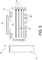
- the ionization-based detection member 19 is now considered in greater detail. It should be noted that such ionization-based detection member 19 can be considered, in some aspects, as a miniaturized and optimized mass spectrometer, in terms that will be better described herein below.
- the above-mentioned ionization region 20 contains gas particles, whose pressure is to be measured, and is arranged in such a way to be crossed by ionization electrons generated by the source 21, so that the ionization particles ionize the gas particles, thereby generating respective ions.
- the above-mentioned ion extraction means 22 are configured to determine a preferred trajectory for the generated ions, within the ionization region 20, towards at least one ion extraction window 31.
- the above-mentioned at least one ion detector 23 has micrometric dimensions and is arranged at the respective at least one ion extraction window 31, such as to be shielded against trajectories of X-rays generated by impacts of the ionizing electrons with parts of the ionization region 20 other than the ion detector 23.
- micrometric dimensions is meant that the ion detector 23 dimensions are of a micrometric or sub-millimetric order of magnitude. More specifically, the ion detector 23 has an impact surface whose sides (if it has a square or polygonal shape) or whose radius (if it has a circular shape) are of the order of magnitude of tens or hundreds ⁇ m (micron) - and anyway sub-millimetric (e.g., about 100 ⁇ m) - such that the area of the impact surface is of a micrometric order of magnitude, i.e., less than one mm 2 .
- the ionization source 21 comprises at least one electron emission source.
- This source can be for example an “El (Electron Ionization) Smart” source, particularly a “cold” field-effect emission source, such as a nano-tubes and/or micro-tips source; the "cold" emission source increases the ionization efficiency even at extremely low pressures.
- the ionization source can be a plasma (o glow) source, or a chemical ionization (CI) source, or another source, per - se known, suitable to cause particle ionization according to one of the known ionization methods.
- the ionization region 20 can be described as a "chamber" of microscopic dimensions, for example, parallelepiped shaped with sidewalls forming a grid 30 on which the electrons can collide and recombine.
- the ionization source 21 can be arranged, emitting particles (for example electrons) that are capable to ionize the gas particles in the "chamber", which electrons travel in an almost straight direction towards the opposite wall (grid).
- the ion extraction means 22 are configured to generate suitable electromagnetic fields, such as to extract the ionized particles, thus charged, from inside the chamber and drive them, by means of electromagnetic interaction, along a desired trajectory, or preferential trajectory, passing through one or more preset exit points, where the one or more above-mentioned "extraction windows" 31 are arranged.
- the extraction windows 31 can be at different points in the ionization region 20 grid.
- the extraction windows can be placed, for example, at the walls that are perpendicular relative to the wall where the ionization source 21 is located, such as to determine ion exit trajectories that are 90°-angled with respect to the electron path 33.
- exit trajectory is 180°-angled or inclined at a different angle, relative to the electron path (see for example Figs. 2 and 3 ).
- the ion extraction means 22 can be made by means of one or more ion guides 22.
- such ion guides 22 can consist of ion extraction nozzles 22 and/or electrostatic lenses 22 and/or electrostatic sectors and/or magnetic sectors.
- the ion guides 22 can be implemented by means of a quadrupole mass filter without bias, per - se known (as will be illustrated below), or by means of a radiofrequency hexapole or octupole or by an electrical or magnetic sector.
- Each of the one or more ions detectors 23 can be made by means of a per - se known detector, which is sensitive to ions colliding on its surface, and configured to generate the above-mentioned second electrical signal S 2 (typically, an electrical current) proportional to the colliding ions number. Since the colliding ions number is proportional to the concentration of ions present in the ionization region 20, which is in turn proportional to the number of gas particles present in the ionization region 20, and thus to the pressure, it is concluded that the second electrical signal S 2 generated by the ion detector 23 is representative, with great precision, of the pressure inside the ionization region.
- S 2 typically, an electrical current
- the ion detector 23 can be implemented by employing, on a miniaturized scale, principles used for example in known detectors of the Faraday cup, or SEM, or Channeltron types.
- the structure of the ionization-based detection member 19 described above allows to drastically reduce, up to almost cancel, the undesired effects due to the X-rays generated in the ionization region 20 when the electrons emitted by the source recombine on the grid 30.
- X-rays collide on the one or more ions detectors 23, they generate a spurious signal (for example, a spurious electrical current) which disturbs the correct signal (representative of the number of detected ions and thus of the pressure), generates noise, and finally reduces the instrument sensitivity.
- each of the one or more ion detectors 23 is arranged outside the ionization region 20, i.e., beyond the grids 30 defining the same, and is connected to the same only by means of the one or more respective extraction windows 31, through which the ions to be detected pass.
- the spurious signal generated by the X-rays and the consequent interference is reduced to a corresponding fraction.
- each of the ion detectors 23 has micrometric dimensions, and the reduction of the impact surface causes a proportional reduction of the amount of impacting X-rays.
- the ion extraction means 22 further comprise X-ray radiations shielding means, configured to shield the at least one ion detector relative to X-rays, such as to reduce its exposure to X-rays.
- X-ray radiations shielding means can be for example the same extraction lenses 22, or specifically arranged shielding nozzles.
- the device 1 further comprises magnetic field generation means 32 (for example, a magnet, or a ferromagnetic material member), configured to generate a magnetic field such as to affect the trajectory of the ionizing electrons in a desired way.
- magnetic field generation means 32 for example, a magnet, or a ferromagnetic material member
- this trajectory can be made helicoidal.
- the casing 13 is configured to adopt a closed state and an open state: in the closed state, it protects the at least one second sensor member 12 from being directly exposed to the surrounding environment; in the open state, it allows the at least one second sensor member to be directly exposed to the surrounding environment.
- the casing 13 When the casing 13 is closed and sealed, it encloses the second sensor member 12, thus protecting it from degradation phenomena possibly resulting from environmental conditions, and at the same time keeping fixed pressure conditions, stabilized on a known value (the above-mentioned "reference pressure” value P ref ) which is a certain and absolute reference point defined a priori.
- the second sensor member 12 keeps the “nominal behaviour", for which it has been carefully characterized a priori, with a good or excellent accuracy.
- the second sensor member takes the important function of "reference sensor”, having a stable and anyway predictable behaviour, even during operation.
- the electro-mechanical or mechatronic properties of the second reference sensor member 12 are known, since they have been characterized a priori with respect to the reference pressure, for example, as a function of operating temperature, oscillation frequency, oscillation amplitude, and so on; and they have been further stored in a memory included in the electronic processing means 10.
- the characterization data of the reference sensor 12 actually define a "reference hypersurface" allowing to know exactly the mechatronic properties of the sensor member and the operating conditions (for example, operating temperature), based on the reference electrical signal S ref generated by the reference sensor 12, and being known the reference pressure to which it is subjected inside the sealed casing.
- the processing means 10 when the processing means 10 receive an electrical signal S ref from the reference sensor 12, they refer it to the known reference pressure value P ref , as maintained inside the sealed casing 13, and thus, based on the stored characterization data, the processing means 10 can know both the mechatronic properties and the operating conditions of the reference sensor 12. Consequently, the processing means 10 are also able to calculate the exact conversion factor existing between S ref and P ref (which will be herein designated as "reference conversion factor").
- the operating conditions of the reference sensor 12 are essentially the same conditions, except for the pressure, that are undergone by the first electro-mechanic sensor member 11 and by the ionization-based detection member 19, which members are very close to each other in the device 1.
- the processing means 10 are able to calculate a suitable conversion factor (which will be herein designated as "first conversion factor”, or “first calibration factor”) to be applied to the signal S 1 generated by the first sensor member 11, in order to calculate exactly the pressure value P to which the first sensor member 11, thus the device 1, is subjected, i.e., the value to be measured.
- first conversion factor or “first calibration factor”
- the processing means 10 are able to calculate another suitable conversion factor (which will be herein designated “second conversion factor” or “second calibration factor”) to be applied to the signal S 2 generated by the ionization-based detection member 19, in order to calculate exactly the pressure value P to which this detection member 19, thus the device 1, is subjected, i.e., the value to be measured.
- second conversion factor or “second calibration factor”
- the first and second conversion factors are indeed correlated in a deterministic and known manner (because of the initial characterization) to the reference conversion factor.
- the processing means 10 are capable in any case to estimate more accurately the actual pressure present at the device, i.e., the measured pressure P, taking into both the reference electrical signal S ref , on the one hand, and the first S 1 or second S 2 electrical signals, on the other hand.
- the device includes a plurality of reference sensor members 12 to detect a respective plurality of reference pressure values P ref
- the electronic processing means 10 are further configured to generate the measured pressure value P based on a processing of the detected reference pressure values P ref .
- the plurality of "reference sensors" can be exploited both to improve the estimate precision, along the whole measurement range of the device, and for the sake of redundancy and reliability.
- two different reference sensor members 12 may be provided, one for each of the above-mentioned members.
- the electronic processing means 10 are configured to process data received from the first sensor member 11 or from the detection member 19, on the one side, and from the reference sensor 12, on the other side.
- the electronic processing means 10 are further configured, based on such received data, to carry out a diagnostic procedure on the first sensor member 11, such as to identify potential hysteresis phenomena and/or imperfections and/or potential thermal and/or mechanical drifts which the first sensor member is subject to, and/or a diagnostic procedure of the ionization-based detection member 19, such as to identify possible performances degradation phenomena which the ionization-based detection member is subject to.
- the signals S 1 or S 2 , on the one side, and the reference signal S ref , on the other side are compared.
- the difference between the reference signal S ref and the electrical signal S 1 (or S 2 depending on the case is a relatively small quantity, less than a preset threshold, it means that the first sensor member 11 (or the ionization-based detection member 19, respectively) works well, and diagnostics have a positive outcome; possibly, the detected difference is compensated by acting on the above-mentioned first conversion factor (or second conversion factor, respectively), in a way similar to what described above about the calibration.
- the device 1 is capable to carry out a diagnostic procedure even if the external environment pressure is not known, or if it does not coincide with the reference pressure, as long as this pressure is within the operation range of the reference sensor 12.
- the casing 13 is temporarily opened, such as to temporarily expose the second sensor member 12 to the same environment to which the first sensor member 11 and the ionization-based detection member 19 are exposed. Then, the diagnostic procedure is performed, and finally the casing 13 is closed and sealed again and the reference pressure conditions are restored, for example by means of an embedded "getter".
- the electronic processing means 10 are further configured to carry out an adjusting procedure of the device 1, based on the results of said diagnostic procedure.
- This adjustment procedure includes an adjusting and/or compensation and/or optimization procedure of the first sensor member 11, to correct and/or compensate hysteresis phenomena and/or imperfections and/or identified drifts, and also an adjusting and/or compensation and/or optimization procedure on the ionization-based detection member to correct and/or compensate performances degradation phenomena.
- the adjustment can be performed also based on optimization procedures directly operating on the electrical/electronic variables on which the detection mechanism is based.
- the device 1 further comprises controlled heating means, comprising one or more temperature sensors 61 (miniaturized thermometer(s)) and at least one heating member 62 (for example, one or more micro-resistors), placed near and/or over the first sensor member 11 and the ionization-based detection member 19, and a heat supply (or "heater") 63.
- the heating member 62 is configured to carry out a degassing and/or a removal of gases adsorbed on the micro-cantilever 11 surface of the first sensor member 11, and in suitable portions of the ionization-based detection member 19. This is done under the control of the electronic processing means 10, which in turn operate based on the temperature detected by the thermometer 61 and on the results of the diagnostic procedure.
- the above-mentioned adjusting procedure of the first sensor member 11 comprises the degassing and/or removal of gases adsorbed on the micro-cantilever 11 surface, by means of the controlled heating means.
- the above-mentioned adjusting procedure of the ionization-based detection member 19 comprises the degassing and/or removal of gases adsorbed in portions of the ionization-based detection member 19, by means of the controlled heating means.
- heat supply 63 can be used to vary the operating thermal conditions of the device, in a controlled manner, also in operating steps other than self-adjusting.
- the device 1 further comprises specific protection technical thin films configured to reduce the adsorption of process gases (for example hydrophobic films to prevent the adsorption of moisture present in the process environment) and to prevent corrosion phenomena.
- These protection thin films are arranged such as to cover at least the first sensor member 11 and the ionization-based detection member 19.
- the device further comprises a package 80 comprising micrometric frame filters, and/or anti-particulate filters, arranged such as to cover at least the sensor members 11, 12, and the ionization-based detection member 19 included in the device 1, and configured to protect them from particulate or soot.
- a package 80 comprising micrometric frame filters, and/or anti-particulate filters, arranged such as to cover at least the sensor members 11, 12, and the ionization-based detection member 19 included in the device 1, and configured to protect them from particulate or soot.
- the electronic processing means 10 comprise at least one electronic processor (CPU) 52 integrated in the device 1. This CPU can then operate as an embedded on-chip programmable microprocessor.
- CPU electronic processor
- the interface means 15 comprise input and output means, wireless or wired and/or with pins.
- this interface can interact with the external world (for example with an external plant control system) in a versatile and adaptable manner, both to transmit and to receive information and/or signals and/or commands.
- the interface means 15 comprise both wired input means 71 and a wireless transmitter 70 (for example a WiFi transmitter), to remotely transmit signals from closed operation areas (such as pump internal zones, process and measurement systems), and output pins 72 able to provide for example a direct analog output signal and/or a digital TTL output signal and/or an interface for a serial communication protocol.
- a wireless transmitter 70 for example a WiFi transmitter
- closed operation areas such as pump internal zones, process and measurement systems
- output pins 72 able to provide for example a direct analog output signal and/or a digital TTL output signal and/or an interface for a serial communication protocol.
- the presence of a CPU 52 and of an interface 15, integrated in the device, allows the device 1 to receive and send information (for example, control signals) from and to a higher-level control system, for example the operating plant/environment control system where the device operates. Thereby, the device 1 is completely integrated in this operating plant/environment.
- information for example, control signals
- the device 1 comprises further embedded electronic circuitry, comprising one or more of the following electronics circuits: dedicated I/O management circuits, a supply and management circuit 64 (connected to an external supply interface 65) of the heating member, a management circuit 67 of the detection member (comprising a voltage supply connected to the ionization-based detection member 19 parts that require to be kept to controllable voltages), a processing circuit 66 of the signal coming from the at least one ion detector 23 of the detection member (comprising inter alia a current/voltage converter).
- dedicated I/O management circuits dedicated I/O management circuits
- a supply and management circuit 64 connected to an external supply interface 65
- a management circuit 67 of the detection member comprising a voltage supply connected to the ionization-based detection member 19 parts that require to be kept to controllable voltages
- a processing circuit 66 of the signal coming from the at least one ion detector 23 of the detection member comprising inter alia a current/voltage converter.
- auxiliary electronic circuits optionally present in the device 1 (frequency generator 51, lock-in circuit 52, heater 53, dedicated I/O management circuits, management circuits 67 of the detection member, etc.). These auxiliary electronic circuits are integrated in the device 1. Optionally, they can be made in the same chip containing the sensor members, the processing means and the interface means, or in further chip, micro-connected to the above mentioned main chip, such as to constitute the integrated device.
- FIG. 3 shows an embodiment where the chip 40 of the device 1 is a "multi-layer" chip where the ionization-based detection member 19 (with related circuitry and optionally a respective reference sensor) is in one layer; the controlled flow opening/closing means 90 are in another layer; and the sensor member 11 (with related circuitry and optionally a respective reference sensor) is in a further layer.
- the heat generating components for example, the processor 52 or the heating micro-resistor 62
- the heat generating components are "segregated", in the chip layer where they are, on an opposite side relative to the other components. Thereby, the effect of the heat generated by these components on the other components is minimized.
- the heat generating components for example, the processor 52 or the heating micro-resistor 62
- the processor 52 or the heating micro-resistor 62 are "segregated", in the chip layer where they are, on an opposite side relative to the other components.
- the device 1 described above is able to detect pressure values between 10 -13 mbar and 10 4 mbar, wherein the first pressure sub-range comprises for example pressures between 10 -4 mbar and 10 4 mbar and the second pressure sub-range comprises for example pressures between 10 -13 mbar and 10 -4 mbar.
- the ionization-based detection member 19 comprises at least one ion selective filtering member, which is configured to shield the at least one ion detector from all the ions but one respective selected ion, in such a way that the at least one ion detector measures the partial pressure related to such selected ion.
- the filtering member is a filtering member that can be tuned to select and send sequentially different types of ions on the same ion detector, so that such ion detector sequentially measures the partial pressure of the different selected ions, such as to perform a Gas Analysis or Residual Gas Analysis function.
- the ionization-based detection member 19 comprises a plurality of additional ion detectors to detect a respective plurality of ions.
- the plurality of additional ion detectors can be coupled with a respective plurality of ion selective filtering members, or with only one, each of them being configured to shield the respective ion detector from all the ions but a respective selected ion, so that the device operates both as meter of total pressure, and as a meter of partial pressure related to each one of the plurality of selected ions, thereby performing a Gas Analysis or Residual Gas Analysis function.
- each of the at least one ion selective filtering member comprises a quadrupole mass filter, according to operation principles per - se known (described for example in Reinhard - von Zahn, "Das brieflye Massenfilter als Massenspektrometer und Isotopentrenner” Zs. Physik, 152, (1958), 143-182 ; or in Greaves, "Vacuum mass spectrometry", Vacuum, 20, (1970), 65-74 ).
- the filtering member comprises electrical sectors and/or magnetic sectors.
- the device 1 based on the basic structure described at the beginning of this description, can be advantageously adapted such as to also become a device for performing Gas Analysis or Residual Gas Analysis, substantially operating on the ion extraction means 23, and applying theories per - se known in the mass spectrometry field.
- the above-mentioned filter members when made by means of quadrupole filters, are driven by voltages, having different amplitudes and waveforms, for example having a DC amplitude value U, and/or a superimposed oscillation amplitude value V and a superimposed oscillation frequency ⁇ .
- voltages having different amplitudes and waveforms, for example having a DC amplitude value U, and/or a superimposed oscillation amplitude value V and a superimposed oscillation frequency ⁇ .
- the device 1 operates in the following way.
- the first sensor member 11 and the ionization-based detection member 19 cooperate to provide pressure measurements, and the ionization-based detection member 19 operate Gas Analysis or Residual Gas Analysis measurements in low pressure environment conditions.
- the valve 91 of the controlled flow opening/closing means 90 is closed, and the nano-pores of the nano-pores layer 92 are opened, the first sensor member 11 performs pressure measurements, and the ionization-based detection member 19 performs Gas Analysis or Residual Gas Analysis measurements on a low pressure gas mixture having the same gas concentrations as the gas mixture present at the first sensor member 11.
- the method comprises the steps of automatically detecting an operative pressure measurement range, by electronic means 10 of the device 1, based on a sequential turning on of a first sensor member 11 of the device 1, configured to measure pressures within a first sub-range, and of an ionization-based detection member 19 of the device 1, configured to measure pressures within a second sub-range.
- the method comprises the step of detecting a first pressure value P 1 and generating a first electrical signal S 1 representative of the first pressure value P 1 , by the first sensor member 11 of the device 1.
- the method comprises the step of detecting a second pressure value P 2 and generating a second electrical signal S 2 representative of the second pressure value P 2 , by the ionization-based detection member 19.
- the method then comprises the step of determining, by the electronic processing means 10, a measured pressure value P based on the above-mentioned first or second electrical signals, S 1 and S 2 ; and finally of providing in output the measured pressure value P, by interface means 15 of the device 1.
- the method further comprises the step of controlling, by means of the electronic processing means 10, a fluidic communication, which is carried out through controlled flow opening/closing means 90 present in the device 1, between the ionization-based detection member 19 and an environment where the first sensor member 11 is located, to allow the ionization-based detection member to measure gas concentration (thus, gas partial pressure), whichever is the operative pressure range in which the method is operating.
- a fluidic communication which is carried out through controlled flow opening/closing means 90 present in the device 1, between the ionization-based detection member 19 and an environment where the first sensor member 11 is located, to allow the ionization-based detection member to measure gas concentration (thus, gas partial pressure), whichever is the operative pressure range in which the method is operating.
- the above-mentioned first sensor member 11, ionization-based detection member 19, controlled flow opening/closing means 90, electronic processing means 10 and interface means 15 are included in a single integrated device.
- the above-mentioned sequential activation step provides that, when the first sensor member 11 is activated, the controlled flow opening/closing means 90 are in a condition where they seal and insulate the ionization-based detection member 19 from the environment; and also provides that, in case the first sensor member 11 has not provided any significant result, and before the activation of the detection member 19, the controlled flow opening/closing means 90 are put in a condition where they allow a direct macro-fluidic communication between the first sensor member 11 and the detection member 19, thus equalizing the pressures to which they are subjected, while pumping is turned off.
- the method further comprises the step of measuring gas partial pressures, by means of the ionization-based detection member 19, in conditions of macro-fluidic communication between the first sensor member 11 and the ionization-based detection member 19, if the method operates in the second pressure sub-range; or the step of measuring gas partial pressures, by means of the ionization-based detection member 19, in conditions of micro-fluidic communication in molecular regime between the first sensor member 11 and the ionization-based detection member 19, if the method operates in the first pressure sub-range.
- the method further comprises the steps of storing characterization data of a further reference sensor member 12 of the device 1, at a reference pressure P 2 in the electronic processing means 10; maintaining the further reference sensor member 12 at the reference pressure P 2 , inside a casing 13; calibrating the first sensor member 11, the ionization-based detection member 19 and the further reference sensor member 12, by means of the electronic processing means 10, based on a reference electrical signal S 2 generated by the reference sensor member 12 and based on the above-mentioned characterization data.
- the object of the present invention is achieved by the system described above, by virtue of the illustrated characteristics.
- the device of the present invention is a miniaturized device capable of maintaining high precision and reliability performances, and moreover capable of measuring pressures within a very wide range of at least 18 orders of magnitude, from 10 -13 mbar to 10 4 mbar, thus becoming an almost universal single device for pressure measurements.
- the same device allows advantageously to also perform Gas Analysis or Residual Gas Analysis functions over the entire measurable pressure range.
- the device proves to be self-contained, because it is capable of self-calibration and self-diagnostic.
- the device is able to deal with, and to correct up to a certain extent, the several degradation causes that may actually arise and which would worsen the device performances, by affecting the sensor members.
- the device allows, as illustrated above, to manage microscopic signals at microscopic level, with the consequent further advantage to enhance the achievable signal-to-noise ratios.
Landscapes
- Physics & Mathematics (AREA)
- General Physics & Mathematics (AREA)
- Measuring Fluid Pressure (AREA)
Claims (13)
- Miniaturisierte Vorrichtung (1) für Druckmessungen über einen sehr breiten Bereich und für Gaskonzentrationsmessungen, umfassend:- wenigstens ein erstes elektromechanisches miniaturisiertes Sensorelement (11), welches dazu eingerichtet ist, einen ersten Druckwert (P1) in einem ersten Unterbereich von messbaren Drücken zu erfassen und ein erstes elektrisches Signal (S1) zu erzeugen, welches den ersten Druckwert (P1) darstellt;- ein Ionisations-basiertes Erfassungselement (19), welches dazu eingerichtet ist, einen zweiten Druckwert (P2) in einem zweiten Unterbereich von messbaren Drücken zu erfassen und umfassend wenigstens eine lonisationsquelle (21), einen lonisationsbereich (20), lonen-Extraktionsmittel (22) und wenigstens einen lonendetektor (23), welcher dazu eingerichtet ist, Ionen zu erfassen und ein zweites elektrisches Signal (S2) zu erzeugen, welches von der Menge von erfassten Ionen abhängt und den zweiten Druckwert (P2) darstellt;- geregelte/gesteuerte Strom-Öffnungs-/Schließ-Mittel (90), welche dazu eingerichtet sind, eine fluidische Kommunikation zwischen dem Ionisations-basierten Erfassungselement (19) und einer Umgebung zu regeln/steuern, in welcher das erste Sensorelement (11) angeordnet ist;- elektronische Verarbeitungsmittel (10), welche mit dem ersten Sensorelement (11) und dem Ionisations-basierten Erfassungselement (19) betriebsmäßig verbunden sind und dazu eingerichtet sind, einen gemessenen Druckwert (P) auf Grundlage des ersten (S1) und des zweiten (S2) erfassten elektrischen Signals zu bestimmen; wobei die elektronischen Verarbeitungsmittel (10) ferner mit den geregelten/gesteuerten Strom-Öffnungs-/Schließ-Mitteln (90) betriebsmäßig verbunden sind und ferner dazu eingerichtet sind, den Zustand davon zu regeln/steuern;- Schnittstellenmittel (15), welche mit den elektrischen Verarbeitungsmitteln (10) betriebsmäßig verbunden sind und dazu eingerichtet sind, den gemessenen Druckwert (P) als Ausgabe bereitzustellen,wobei:- das erste Sensorelement (11), das Ionisations-basierte Erfassungselement (19), die geregelten/gesteuerten Strom-Öffnungs-/Schließ-Mittel (90), die elektronischen Verarbeitungsmittel (10) und die Schnittstellenmittel (15) in einer einzelnen integralen Vorrichtung umfasst sind;- die geregelten/gesteuerten Strom-Öffnungs-/Schließ-Mittel (90) dazu eingerichtet sind, in einer geregelten/gesteuerten Weise das Folgende anzunehmen: einen geschlossenen Zustand, in welchem sie das Ionisations-basierte Erfassungselement (19) in Bezug auf die Umgebung abdichten und isolieren, welcher das erste Sensorelement (11) ausgesetzt ist; einen mikrofluidischen Öffnungszustand, in welchem sie eine makrofluidische Kommunikation verhindern, während eine mikrofluidische Kommunikation zwischen dem Ionisations-basierten Erfassungselement (19) und dem ersten Sensorelement (11) erlaubt wird; einen makrofluidischen Öffnungszustand, in welchem sie eine makrofluidische Kommunikation zwischen dem Ionisations-basierten Erfassungselement (19) und dem ersten Sensorelement (11) erlauben, um sie einer gleichen Druckbedingung auszusetzen;- das Ionisations-basierte Erfassungselement (19) ferner dazu eingerichtet ist, eine Gaskonzentration unter dem mikrofluidischen Öffnungszustand der geregelten/gesteuerten Strom-Öffnungs-/SchließMittel (90) in Anwesenheit eines Drucks, welcher zu dem ersten Unterbereich gehört, zu messen und eine Gaskonzentration unter dem makrofluidischen Öffnungszustand der geregelten/gesteuerten Strom-Öffnungs-/Schließ-Mittel (90) in Anwesenheit eines Drucks, welcher zu dem zweiten Unterbereich gehört, zu messen.
- Vorrichtung (1) nach Anspruch 1, welche eine dreidimensionale Konfiguration aufweist, und wobei sich jedes aus dem ersten Sensorelement (11), dem Ionisations-basierten Erfassungselement (19) und den geregelten/gesteuerten Strom-Öffnungs-/Schließ-Mitteln (90) entlang von zwei Richtungen erstreckt, wobei die geregelten/gesteuerten Strom-Öffnungs-/Schließ-Mittel (90) dazu eingerichtet sind, eine Fluid-Kommunikation zwischen dem Ionisations-basierten Erfassungselement (19) und dem ersten Sensorelement (11) zu regeln/steuern;
und wobei das erste Sensorelement (11), das Ionisations-basierte Erfassungselement (19) und die geregelten/gesteuerten Strom-Öffnungs-/Schließ-Mittel (90) entlang der dritten Richtung, welche rechtwinklig zu den ersten beiden ist, überlagert sind, so dass, in Betrachtung der dritten Richtung, die geregelten/gesteuerten Strom-Öffnungs-/Schließ-Mittel (90) zwischen dem ersten Sensorelement (11) und dem Ionisations-Erfassungselement (19) angeordnet sind. - Vorrichtung (1) nach einem der vorhergehenden Ansprüche, ferner umfassend ein miniaturisiertes Pumpelement (93), welches dazu eingerichtet ist, Gase von dem Ionisations-basierten Erfassungselement (19) zu pumpen, um einen Druckgradienten, falls es unter der Regelung/Steuerung der Verarbeitungsmittel (10) eingeschaltet wird, zwischen dem ersten Sensorelement (11) und dem Ionisations-basierten Erfassungselement (19) zu halten.
- Vorrichtung (1) nach den Ansprüchen 1 und 3, wobei die geregelten/gesteuerten Strom-Öffnungs-/Schließ-Mittel (90) umfassen:- wenigstens ein Ventil (91), welches dazu eingerichtet ist, einen Öffnungszustand, in welchem es eine makrofluidische Kommunikation zwischen dem ersten Sensorelement (11) und dem Ionisationsbasierten Erfassungselement (19) erlaubt, so dass sie bei den selben Druckbedingungen vorliegen, falls das miniaturisierte Pumpelement (93) nicht eingeschaltet ist, und einen geschlossenen Zustand einzunehmen, in welchem die makrofluidische Kommunikation nicht erlaubt ist;- eine mikrofluidische Kommunikationsschicht (92), umfassend Nanoporen, welche dazu geeignet sind, in einer geregelten/gesteuerten Weise geöffnet oder geschlossen zu werden, welche dazu eingerichtet sind, jeweilige Mikroströme von Gas passieren zu lassen oder nicht, wobei die mikrofluidische Kommunikationsschicht (92) dazu eingerichtet ist, in einer wählbaren und geregelten/gesteuerten Weise das erste Sensorelement (11) und das Ionisations-Erfassungselement (19) in mikrofluidische Kommunikation zu setzen, falls das Ventil (91) in einem geschlossenen Zustand ist, und, falls das miniaturisierte Pumpelement (93) eingeschaltet ist, um die Gaskonzentration zwischen dem ersten Sensorelement (11) und dem Ionisations-basierten Erfassungselement (19) einheitlich zu machen, während ein voneinander unterschiedlicher Druck gehalten wird.
- Vorrichtung (1) nach einem der vorhergehenden Ansprüche, wobei der Bereich von messbaren Drücken in zwei Mess-Unterbereiche unterteilt ist, und wobei die elektronischen Verarbeitungsmittel (10) dazu eingerichtet sind, den gemessenen Druckwert (P) als mit dem ersten (P1) oder, falls das Ventil in Öffnungszuständen vorliegt, mit dem zweiten (P2) erfassten Druckwert in Abhängigkeit der Tatsache, dass der zu messende Druck dem einen oder dem anderen der Mess-Unterbereiche angehört, zusammenfallend zu erzeugen,
und wobei die elektronischen Verarbeitungsmittel (10) dazu eingerichtet sind, den Mess-Unterbereich auf Grundlage eines sequenziellen Einschaltens der Vorrichtung automatisch zu erfassen, beginnend bei dem ersten Sensorelement (11). - Vorrichtung (1) nach einem der vorhergehenden Ansprüche, wobei das erste Sensorelement (11), das Ionisations-basierte Erfassungselement (19), die geregelten/gesteuerten Strom-Öffnungs-/Schließ-Mittel (90), die elektronischen Verarbeitungsmittel (10) und die Schnittstellenmittel (15) in einem einzelnen Chip einer integralen Vorrichtung umfasst sind.
- Vorrichtung (1) nach einem der vorhergehenden Ansprüche, ferner umfassend wenigstens ein zweites miniaturisiertes elektromechanisches Drucksensorelement (12), welches innerhalb eines jeweiligen Gehäuses (13) angeordnet ist, welches dazu geeignet ist, das zweite Sensorelement (12) abzudichten, und dazu eingerichtet ist, einen dritten Druckwert (Pref) zu erfassen, welcher als ein Referenzdruckwert (Pref) wirkt, und wobei jedes aus dem ersten (11) und dem zweiten (12) Sensorelement ein jeweiliges Oszillatioselement des MEMS/NEMS-Typs umfasst, welches dazu eingerichtet ist, mit einer dynamischen Reaktion, welche von dem Druck abhängt, welchem es ausgesetzt ist, oszilliert.
- Vorrichtung (1) nach einem der vorhergehenden Ansprüche, wobei der lonisationsbereich (20) des Ionisations-basierten Erfassungselements (19) Gaspartikel enthält, deren Druck zu messen ist, und er dazu eingerichtet ist, von Ionisationspartikeln, welche durch die lonisationsquelle (21) erzeugt werden, durchlaufen zu werden, so dass die lonisationspartikel die Gaspartikel ionisieren, wobei entsprechende Ionen erzeugt werden;
und wobei die lonen-Extraktionsmittel (22) dazu eingerichtet sind, eine Vorzugstrajektorie für die erzeugten Ionen zu bestimmen, welche durch wenigstens ein lonen-Extraktionsfenster führt, durch welches die Ionen den lonisationsbereich (20) verlassen, wobei die Ionen-Extraktionsmittel (22) wenigstens eine Ionen-Führung und/oder Röntgenstrahlungs-Abschirmungsmittel umfassen, welche dazu eingerichtet sind, den wenigstens einen lonendetektor (23) gegen die Röntgenstrahlen abzuschirmen, um dessen Aussetzung gegenüber Röntgenstrahlen zu reduzieren;
und wobei der wenigstens eine lonendetektor (23) Mikrometer-Abmessungen aufweist, und wobei er jeweils an dem wenigstens einen lonen-Extraktionsfenster angeordnet ist, um gegen Trajektorien von Röntgenstrahlen abgeschirmt zu sein, welche durch Einschläge der ionisierten Elektronen mit Teilen des lonisationsbereichs (20), welche von dem wenigstens einen lonendetektor (23) verschieden sind, erzeugt werden. - Vorrichtung (1) nach Anspruch 8, wobei die elektronischen Verarbeitungsmittel (10) einen Speicher umfassen, welcher dazu eingerichtet ist, Charakterisierungsdaten zu speichern, welche das Referenz-Sensorelement (12) bei dem Referenzdruck (Pref) charakterisieren, wobei die Verarbeitungsmittel (10) ferner mit dem zweiten Sensorelement (12) verbunden sind, um das elektrische Referenzsignal (Sref) zu empfangen,
und wobei die elektronischen Verarbeitungsmittel (10) dazu eingerichtet sind, das erste Sensorelement (11), das Ionisations-Erfassungselement (19) und das Referenz-Sensorelement (12) auf Grundlage des elektrischen Referenzsignals (Sref) und der gespeicherten Charakterisierungsdaten zu kalibrieren,
und wobei die elektronischen Verarbeitungsmittel (10) ferner dazu eingerichtet sind, die Daten, welche von dem zweiten Referenz-Sensorelement (12) empfangen werden, zu verarbeiten und auf Grundlage der empfangenen Daten das Folgende auszuführen:- eine Diagnose-Prozedur des Ionisations-Erfassungselements (19), um mögliche Leistungsabfall-Phänomene zu identifizieren, welchen das Ionisations-Erfassungselement (19) ausgesetzt ist, und- eine Diagnose-Prozedur des ersten Sensorelements (11), um mögliche Hysterese-Phänomene und/oder Mängel und/oder mögliche thermische und/oder mechanische Abweichungen zu identifizieren, welchen das erste Sensorelement (11) ausgesetzt ist,und wobei die elektronischen Verarbeitungsmittel (10) dazu eingerichtet sind, in dem Fall, dass die Diagnose-Prozedur ein negatives Ergebnis liefert, das Folgende auszuführen:- eine Einstellung und/oder Kompensation und/oder Optimierungsprozedur des ersten Sensorelements (11), um die identifizierten Hysterese-Phänomene und/oder Mängel und/oder Abweichungen auf Grundlage der Ergebnisse der Diagnose-Prozedur zu korrigieren;- eine Einstellung und/oder Kompensation und/oder Optimierungsprozedur an dem Ionisations-Erfassungselement (19) um Leistungsabfall-Phänomene zu korrigieren und/oder zu kompensieren, welche auf Grundlage der Ergebnisse der Diagnose-Prozedur identifiziert worden sind. - Vorrichtung (1) nach einem der vorhergehenden Ansprüche, welche dazu eingerichtet ist, Druckwerte zu erfassen, welche im Bereich von 10-13 mbar und 10-4 mbar liegen, wobei der erste Unterbereich von Drücken Drücke zwischen 10-4 mbar und 104 mbar umfasst, welche mittels des ersten elektromechanischen miniaturisierten Sensorelements (11) erfassbar sind, und der zweite Unterbereich von Drücken Drücke zwischen 10-13 mbar und 10-4 mbar umfasst, welche mittels des Ionisations-basierten Erfassungselements (19) erfassbar sind.
- Vorrichtung (1) nach einem der vorhergehenden Ansprüche, wobei das Ionisations-basierte Erfassungselement (19) wenigstens ein selektives lonen-Filterelement umfasst, welches dazu eingerichtet ist, den wenigstens einen lonendetektor (23) gegen all die Ionen mit Ausnahme eines jeweiligen ausgewählten Ions abzuschirmen, so dass der wenigstens eine lonendetektor (23) den partiellen Druck relativ zu dem ausgewählten Ion misst,
und wobei das Filterelement ein einstellbares Filterelement ist, um in Reihe Ionen von verschiedenen Typen an einem gleichen lonendetektor (23) auszuwählen und zu senden, so dass der lonendetektor (23) in Reihe den partiellen Druck und/oder die Konzentration der verschiedenen ausgewählten Ionen misst,
und wobei das Ionisations-Erfassungselement (19) eine Mehrzahl von zusätzlichen lonendetektoren (23) umfasst, um eine jeweilige Mehrzahl von Ionen zu erfassen, wobei die Mehrzahl von zusätzlichen lonendetektoren (23) mit einer jeweiligen Mehrzahl der selektiven lonen-Filterelemente gekoppelt ist, wobei jedes der selektiven Ionen-Filterelemente dazu eingerichtet ist, den jeweiligen lonendetektor (23) gegen all die Ionen mit Ausnahme eines jeweiligen ausgewählten Ions abzuschirmen, so dass die Vorrichtung (1) sowohl als ein Messgerät eines totalen Drucks als auch als ein Messgerät eines partiellen Drucks relativ zu jeder der Mehrzahl der ausgewählten Ionen wirkt. - Vorrichtung (1) nach Anspruch 11, wobei:- falls das Ventil (91) der geregelten/gesteuerten Strom-Öffnungs-/Schließ-Mittel (90) offen ist, das erste Sensorelement (11) und das Ionisations-basierte Erfassungselement (19) zusammenwirken, um Druckmessungen bereitzustellen, und das Ionisations-Erfassungselement (19) Messungen von Gasanalysen oder Restgasanalysen durchführt, falls es in Zuständen von geringem Umgebungsdruck vorliegt;- falls hohe Umgebungsdruck-Zustände vorliegen, das Ventil (91) der geregelten/gesteuerten Strom-Öffnungs-/Schließ-Mittel (90) geschlossen ist, und die Nanoporen der Schicht von Nanoporen (92) offen sind, wobei das erste Sensorelement (11) Druckmessungen durchführt und das Ionisations-basierte Erfassungselement (19) Messungen einer Gasanalyse oder Restgasanalyse an einem Gemisch von Niederdruck-Gasen mit der gleichen Gaskonzentration wie das Gemisch von Gasen, welches an dem ersten Sensorelement (11) vorliegt, durchführt.
- Verfahren zum Messen eines Drucks und einer Konzentration von Gasen über einen sehr breiten Bereich von Drücken durch eine miniaturisierte Vorrichtung (1), wobei das Verfahren die Schritte umfasst:- automatisches Erfassen eines operativen Druckmessbereichs durch elektronische Mittel (10) der Vorrichtung (1) auf Grundlage eines sequenziellen Einschaltens eines ersten Sensorelements (11) der Vorrichtung (1), welches dazu eingerichtet ist, Drücke in einem ersten Unterbereich zu messen, und eines Ionisations-basierten Erfassungselements (19) der Vorrichtung (1), welches dazu eingerichtet ist, Drücke in einem zweiten Unterbereich zu messen;- falls der erfasste operative Unterbereich der erste Unterbereich ist, Erfassen eines ersten Druckwerts (P1) und Erzeugen eines ersten elektrischen Signals (S1), welches den ersten Druckwert (P1) darstellt, durch das erste Sensorelement (11);- falls der erfasste operative Unterbereich der zweite Unterbereich ist, Erfassen eines zweiten Druckwerts (P2) und Erzeugen eines zweiten elektrischen Signals (S2), welches den zweiten Druckwert (P2) darstellt, durch das Ionisations-Erfassungselement (19);- Bestimmen durch die elektronischen Verarbeitungsmittel (10) eines gemessenen Druckwerts (P) auf Grundlage des ersten (S1) oder des zweiten elektrischen Signals (S2);- Bereitstellen des gemessenen Druckwerts (P) als Ausgabe durch Schnittstellenmittel (15) der Vorrichtung (1);- Regeln/Steuern durch die elektronischen Verarbeitungsmittel (10) mittels der geregelten/gesteuerten Strom-Öffnungs-/Schließ-Mittel (90) der Vorrichtung (1) einer fluidischen Kommunikation zwischen dem lonisations-Erfassungselement (19) und einer Umgebung, in welcher das erste Sensorelement (11) angeordnet ist, um dem Ionisations-Erfassungselement (19) zu erlauben, Gaskonzentrationen zu messen, was auch immer der operative Druckbereich ist, in welchem das Verfahren ausgeführt wird;wobei das Verfahren ferner die Schritte umfasst:
wobei das erste Sensorelement (11), das Ionisations-basierte Erfassungselement (19), die geregelten/gesteuerten Strom-Öffnungs-/Schließ-Mittel (90), die elektronischen Verarbeitungsmittel (10) und die Schnittstellenmittel (15) in einer einzelnen integralen Vorrichtung umfasst sind;- Messen von partiellen Gasdrücken durch das Ionisations-basierte Erfassungselement (19) unter makrofluidischen Kommunikationszuständen zwischen dem ersten Sensorelement (11) und dem Ionisations-basierten Erfassungselement (19), falls das Verfahren in dem zweiten Unterbereich von Drücken ausgeführt wird;- oder Messen von partiellen Gasdrücken durch das Ionisations-basierte Erfassungselement (19) unter mikrofluidischen Kommunikationszuständen in einem molekularen System zwischen dem ersten Sensorelement (11) und dem Ionisations-basierten Erfassungselement (19), falls das Verfahren in dem ersten Unterbereich von Drücken ausgeführt wird.
Applications Claiming Priority (2)
| Application Number | Priority Date | Filing Date | Title |
|---|---|---|---|
| ITMI20140137 | 2014-01-31 | ||
| PCT/IB2015/050679 WO2015114558A2 (en) | 2014-01-31 | 2015-01-29 | Miniaturized device for measurements of pressure over a very wide range, of gas concentrations and residual gas analysis |
Publications (2)
| Publication Number | Publication Date |
|---|---|
| EP3100019A2 EP3100019A2 (de) | 2016-12-07 |
| EP3100019B1 true EP3100019B1 (de) | 2018-11-14 |
Family
ID=50624933
Family Applications (1)
| Application Number | Title | Priority Date | Filing Date |
|---|---|---|---|
| EP15708310.6A Active EP3100019B1 (de) | 2014-01-31 | 2015-01-29 | Miniaturisiertes gerät zur messung von druck über ein sehr breites spektrum von gaskonzentrationen und restgasanalyse |
Country Status (2)
| Country | Link |
|---|---|
| EP (1) | EP3100019B1 (de) |
| WO (1) | WO2015114558A2 (de) |
Family Cites Families (6)
| Publication number | Priority date | Publication date | Assignee | Title |
|---|---|---|---|---|
| US5440931A (en) * | 1993-10-25 | 1995-08-15 | United Technologies Corporation | Reference element for high accuracy silicon capacitive pressure sensor |
| DE19853035A1 (de) * | 1998-11-18 | 2000-05-25 | Arithmed Gmbh Medizinische Mes | Tragbares Mikrodosiersystem zur zeitverzögerten Abgabe von Flüssigkeiten |
| US6452167B1 (en) * | 1998-05-20 | 2002-09-17 | Sandia National Laboratories | Miniature quadrupole mass spectrometer having a cold cathode ionization source |
| US7418869B2 (en) * | 2005-06-10 | 2008-09-02 | Brooks Automation, Inc. | Wide-range combination vacuum gauge |
| US20100024517A1 (en) * | 2008-08-04 | 2010-02-04 | Cary Ratner | Pressure Gauge |
| EP2309241B1 (de) * | 2009-10-07 | 2016-11-30 | ams international AG | MEMS-Drucksensor |
-
2015
- 2015-01-29 WO PCT/IB2015/050679 patent/WO2015114558A2/en not_active Ceased
- 2015-01-29 EP EP15708310.6A patent/EP3100019B1/de active Active
Non-Patent Citations (1)
| Title |
|---|
| None * |
Also Published As
| Publication number | Publication date |
|---|---|
| WO2015114558A2 (en) | 2015-08-06 |
| EP3100019A2 (de) | 2016-12-07 |
| WO2015114558A3 (en) | 2016-11-17 |
Similar Documents
| Publication | Publication Date | Title |
|---|---|---|
| US10578508B2 (en) | Electro-mechanical miniaturized device for pressure measurements | |
| JP5539801B2 (ja) | ガス採取装置、およびそれを使用したガス分析器 | |
| JP2007207758A (ja) | 所定の最終真空圧力を有する粒子光学装置 | |
| EP3100018B1 (de) | Miniaturisiertes gerät zur druckmessung in einem sehr weiten range | |
| KR102857959B1 (ko) | 질량 분석계 및 질량 분석계 보정 방법 | |
| EP3100020B1 (de) | Miniaturisiertes gerät zur messung von sehr niedrigem druck und von gaskonzentrationen | |
| Fedchak et al. | Recommended practice for calibrating vacuum gauges of the ionization type | |
| CN106687808B (zh) | 用于分析时变气流的便携式电子系统 | |
| KR101296275B1 (ko) | 평균 자유 경로를 측정하는 장치, 진공계 및 평균 자유 경로를 측정하는 방법 | |
| EP0310210B1 (de) | Messung von Komponenten in einem Gas | |
| EP3100019B1 (de) | Miniaturisiertes gerät zur messung von druck über ein sehr breites spektrum von gaskonzentrationen und restgasanalyse | |
| US20170133212A1 (en) | Portable electronic device for the analysis of a gaseous composition | |
| KR102781788B1 (ko) | 격막 압력계 및 복합 압력계 | |
| JP5660529B2 (ja) | 酸素検出計、酸素検出機能付き電離真空計及び質量分析計 | |
| EP3167216B1 (de) | Vorrichtung zur erzeugung eines zusammensetzungsgesteuerten und intensitätsgesteuerten ionenstroms und zugehöriges verfahren | |
| Jousten | Pressure measurement with ionization gauges | |
| EP3555904A1 (de) | Anodenelektrodenabschirmung für messgerät der invertierten magnetron-kaltkathodenionisierung | |
| Staikunas | Analysis and Characterization Activities of a Helicon-based Plasma Thruster/Generator as Particle Flow Generator for VLEO Applications | |
| ITTO20090513A1 (it) | Dispositivo di campionamento per gas e apparato analizzatore di gas che impiega detto dispositivo. | |
| Gibbins et al. | Vacuum measurement and process control systems |
Legal Events
| Date | Code | Title | Description |
|---|---|---|---|
| PUAI | Public reference made under article 153(3) epc to a published international application that has entered the european phase |
Free format text: ORIGINAL CODE: 0009012 |
|
| STAA | Information on the status of an ep patent application or granted ep patent |
Free format text: STATUS: REQUEST FOR EXAMINATION WAS MADE |
|
| 17P | Request for examination filed |
Effective date: 20160825 |
|
| AK | Designated contracting states |
Kind code of ref document: A2 Designated state(s): AL AT BE BG CH CY CZ DE DK EE ES FI FR GB GR HR HU IE IS IT LI LT LU LV MC MK MT NL NO PL PT RO RS SE SI SK SM TR |
|
| AX | Request for extension of the european patent |
Extension state: BA ME |
|
| R17D | Deferred search report published (corrected) |
Effective date: 20161117 |
|
| DAX | Request for extension of the european patent (deleted) | ||
| GRAP | Despatch of communication of intention to grant a patent |
Free format text: ORIGINAL CODE: EPIDOSNIGR1 |
|
| STAA | Information on the status of an ep patent application or granted ep patent |
Free format text: STATUS: GRANT OF PATENT IS INTENDED |
|
| RAP1 | Party data changed (applicant data changed or rights of an application transferred) |
Owner name: NANOTECH ANALYSIS S.R.L. |
|
| INTG | Intention to grant announced |
Effective date: 20180329 |
|
| GRAS | Grant fee paid |
Free format text: ORIGINAL CODE: EPIDOSNIGR3 |
|
| GRAA | (expected) grant |
Free format text: ORIGINAL CODE: 0009210 |
|
| STAA | Information on the status of an ep patent application or granted ep patent |
Free format text: STATUS: THE PATENT HAS BEEN GRANTED |
|
| AK | Designated contracting states |
Kind code of ref document: B1 Designated state(s): AL AT BE BG CH CY CZ DE DK EE ES FI FR GB GR HR HU IE IS IT LI LT LU LV MC MK MT NL NO PL PT RO RS SE SI SK SM TR |
|
| REG | Reference to a national code |
Ref country code: CH Ref legal event code: EP Ref country code: AT Ref legal event code: REF Ref document number: 1065401 Country of ref document: AT Kind code of ref document: T Effective date: 20181115 |
|
| REG | Reference to a national code |
Ref country code: DE Ref legal event code: R096 Ref document number: 602015019815 Country of ref document: DE |
|
| REG | Reference to a national code |
Ref country code: IE Ref legal event code: FG4D |
|
| REG | Reference to a national code |
Ref country code: NL Ref legal event code: MP Effective date: 20181114 |
|
| REG | Reference to a national code |
Ref country code: LT Ref legal event code: MG4D |
|
| REG | Reference to a national code |
Ref country code: AT Ref legal event code: MK05 Ref document number: 1065401 Country of ref document: AT Kind code of ref document: T Effective date: 20181114 |
|
| PG25 | Lapsed in a contracting state [announced via postgrant information from national office to epo] |
Ref country code: AT Free format text: LAPSE BECAUSE OF FAILURE TO SUBMIT A TRANSLATION OF THE DESCRIPTION OR TO PAY THE FEE WITHIN THE PRESCRIBED TIME-LIMIT Effective date: 20181114 Ref country code: LT Free format text: LAPSE BECAUSE OF FAILURE TO SUBMIT A TRANSLATION OF THE DESCRIPTION OR TO PAY THE FEE WITHIN THE PRESCRIBED TIME-LIMIT Effective date: 20181114 Ref country code: NO Free format text: LAPSE BECAUSE OF FAILURE TO SUBMIT A TRANSLATION OF THE DESCRIPTION OR TO PAY THE FEE WITHIN THE PRESCRIBED TIME-LIMIT Effective date: 20190214 Ref country code: LV Free format text: LAPSE BECAUSE OF FAILURE TO SUBMIT A TRANSLATION OF THE DESCRIPTION OR TO PAY THE FEE WITHIN THE PRESCRIBED TIME-LIMIT Effective date: 20181114 Ref country code: FI Free format text: LAPSE BECAUSE OF FAILURE TO SUBMIT A TRANSLATION OF THE DESCRIPTION OR TO PAY THE FEE WITHIN THE PRESCRIBED TIME-LIMIT Effective date: 20181114 Ref country code: IS Free format text: LAPSE BECAUSE OF FAILURE TO SUBMIT A TRANSLATION OF THE DESCRIPTION OR TO PAY THE FEE WITHIN THE PRESCRIBED TIME-LIMIT Effective date: 20190314 Ref country code: ES Free format text: LAPSE BECAUSE OF FAILURE TO SUBMIT A TRANSLATION OF THE DESCRIPTION OR TO PAY THE FEE WITHIN THE PRESCRIBED TIME-LIMIT Effective date: 20181114 Ref country code: HR Free format text: LAPSE BECAUSE OF FAILURE TO SUBMIT A TRANSLATION OF THE DESCRIPTION OR TO PAY THE FEE WITHIN THE PRESCRIBED TIME-LIMIT Effective date: 20181114 Ref country code: BG Free format text: LAPSE BECAUSE OF FAILURE TO SUBMIT A TRANSLATION OF THE DESCRIPTION OR TO PAY THE FEE WITHIN THE PRESCRIBED TIME-LIMIT Effective date: 20190214 |
|
| PG25 | Lapsed in a contracting state [announced via postgrant information from national office to epo] |
Ref country code: GR Free format text: LAPSE BECAUSE OF FAILURE TO SUBMIT A TRANSLATION OF THE DESCRIPTION OR TO PAY THE FEE WITHIN THE PRESCRIBED TIME-LIMIT Effective date: 20190215 Ref country code: NL Free format text: LAPSE BECAUSE OF FAILURE TO SUBMIT A TRANSLATION OF THE DESCRIPTION OR TO PAY THE FEE WITHIN THE PRESCRIBED TIME-LIMIT Effective date: 20181114 Ref country code: AL Free format text: LAPSE BECAUSE OF FAILURE TO SUBMIT A TRANSLATION OF THE DESCRIPTION OR TO PAY THE FEE WITHIN THE PRESCRIBED TIME-LIMIT Effective date: 20181114 Ref country code: PT Free format text: LAPSE BECAUSE OF FAILURE TO SUBMIT A TRANSLATION OF THE DESCRIPTION OR TO PAY THE FEE WITHIN THE PRESCRIBED TIME-LIMIT Effective date: 20190314 Ref country code: SE Free format text: LAPSE BECAUSE OF FAILURE TO SUBMIT A TRANSLATION OF THE DESCRIPTION OR TO PAY THE FEE WITHIN THE PRESCRIBED TIME-LIMIT Effective date: 20181114 Ref country code: RS Free format text: LAPSE BECAUSE OF FAILURE TO SUBMIT A TRANSLATION OF THE DESCRIPTION OR TO PAY THE FEE WITHIN THE PRESCRIBED TIME-LIMIT Effective date: 20181114 |
|
| PG25 | Lapsed in a contracting state [announced via postgrant information from national office to epo] |
Ref country code: DK Free format text: LAPSE BECAUSE OF FAILURE TO SUBMIT A TRANSLATION OF THE DESCRIPTION OR TO PAY THE FEE WITHIN THE PRESCRIBED TIME-LIMIT Effective date: 20181114 Ref country code: PL Free format text: LAPSE BECAUSE OF FAILURE TO SUBMIT A TRANSLATION OF THE DESCRIPTION OR TO PAY THE FEE WITHIN THE PRESCRIBED TIME-LIMIT Effective date: 20181114 Ref country code: CZ Free format text: LAPSE BECAUSE OF FAILURE TO SUBMIT A TRANSLATION OF THE DESCRIPTION OR TO PAY THE FEE WITHIN THE PRESCRIBED TIME-LIMIT Effective date: 20181114 |
|
| REG | Reference to a national code |
Ref country code: DE Ref legal event code: R097 Ref document number: 602015019815 Country of ref document: DE |
|
| PG25 | Lapsed in a contracting state [announced via postgrant information from national office to epo] |
Ref country code: RO Free format text: LAPSE BECAUSE OF FAILURE TO SUBMIT A TRANSLATION OF THE DESCRIPTION OR TO PAY THE FEE WITHIN THE PRESCRIBED TIME-LIMIT Effective date: 20181114 Ref country code: SM Free format text: LAPSE BECAUSE OF FAILURE TO SUBMIT A TRANSLATION OF THE DESCRIPTION OR TO PAY THE FEE WITHIN THE PRESCRIBED TIME-LIMIT Effective date: 20181114 Ref country code: EE Free format text: LAPSE BECAUSE OF FAILURE TO SUBMIT A TRANSLATION OF THE DESCRIPTION OR TO PAY THE FEE WITHIN THE PRESCRIBED TIME-LIMIT Effective date: 20181114 Ref country code: SK Free format text: LAPSE BECAUSE OF FAILURE TO SUBMIT A TRANSLATION OF THE DESCRIPTION OR TO PAY THE FEE WITHIN THE PRESCRIBED TIME-LIMIT Effective date: 20181114 Ref country code: MC Free format text: LAPSE BECAUSE OF FAILURE TO SUBMIT A TRANSLATION OF THE DESCRIPTION OR TO PAY THE FEE WITHIN THE PRESCRIBED TIME-LIMIT Effective date: 20181114 |
|
| REG | Reference to a national code |
Ref country code: CH Ref legal event code: PL |
|
| PLBE | No opposition filed within time limit |
Free format text: ORIGINAL CODE: 0009261 |
|
| STAA | Information on the status of an ep patent application or granted ep patent |
Free format text: STATUS: NO OPPOSITION FILED WITHIN TIME LIMIT |
|
| PG25 | Lapsed in a contracting state [announced via postgrant information from national office to epo] |
Ref country code: LU Free format text: LAPSE BECAUSE OF NON-PAYMENT OF DUE FEES Effective date: 20190129 |
|
| REG | Reference to a national code |
Ref country code: BE Ref legal event code: MM Effective date: 20190131 |
|
| 26N | No opposition filed |
Effective date: 20190815 |
|
| REG | Reference to a national code |
Ref country code: IE Ref legal event code: MM4A |
|
| PG25 | Lapsed in a contracting state [announced via postgrant information from national office to epo] |
Ref country code: SI Free format text: LAPSE BECAUSE OF FAILURE TO SUBMIT A TRANSLATION OF THE DESCRIPTION OR TO PAY THE FEE WITHIN THE PRESCRIBED TIME-LIMIT Effective date: 20181114 |
|
| PG25 | Lapsed in a contracting state [announced via postgrant information from national office to epo] |
Ref country code: BE Free format text: LAPSE BECAUSE OF NON-PAYMENT OF DUE FEES Effective date: 20190131 |
|
| PG25 | Lapsed in a contracting state [announced via postgrant information from national office to epo] |
Ref country code: LI Free format text: LAPSE BECAUSE OF NON-PAYMENT OF DUE FEES Effective date: 20190131 Ref country code: CH Free format text: LAPSE BECAUSE OF NON-PAYMENT OF DUE FEES Effective date: 20190131 |
|
| PG25 | Lapsed in a contracting state [announced via postgrant information from national office to epo] |
Ref country code: IE Free format text: LAPSE BECAUSE OF NON-PAYMENT OF DUE FEES Effective date: 20190129 |
|
| PG25 | Lapsed in a contracting state [announced via postgrant information from national office to epo] |
Ref country code: TR Free format text: LAPSE BECAUSE OF FAILURE TO SUBMIT A TRANSLATION OF THE DESCRIPTION OR TO PAY THE FEE WITHIN THE PRESCRIBED TIME-LIMIT Effective date: 20181114 |
|
| PG25 | Lapsed in a contracting state [announced via postgrant information from national office to epo] |
Ref country code: MT Free format text: LAPSE BECAUSE OF NON-PAYMENT OF DUE FEES Effective date: 20190129 |
|
| PG25 | Lapsed in a contracting state [announced via postgrant information from national office to epo] |
Ref country code: CY Free format text: LAPSE BECAUSE OF FAILURE TO SUBMIT A TRANSLATION OF THE DESCRIPTION OR TO PAY THE FEE WITHIN THE PRESCRIBED TIME-LIMIT Effective date: 20181114 |
|
| PG25 | Lapsed in a contracting state [announced via postgrant information from national office to epo] |
Ref country code: HU Free format text: LAPSE BECAUSE OF FAILURE TO SUBMIT A TRANSLATION OF THE DESCRIPTION OR TO PAY THE FEE WITHIN THE PRESCRIBED TIME-LIMIT; INVALID AB INITIO Effective date: 20150129 |
|
| PG25 | Lapsed in a contracting state [announced via postgrant information from national office to epo] |
Ref country code: MK Free format text: LAPSE BECAUSE OF FAILURE TO SUBMIT A TRANSLATION OF THE DESCRIPTION OR TO PAY THE FEE WITHIN THE PRESCRIBED TIME-LIMIT Effective date: 20181114 |
|
| P01 | Opt-out of the competence of the unified patent court (upc) registered |
Effective date: 20230601 |
|
| PGFP | Annual fee paid to national office [announced via postgrant information from national office to epo] |
Ref country code: FR Payment date: 20251231 Year of fee payment: 12 |
|
| PGFP | Annual fee paid to national office [announced via postgrant information from national office to epo] |
Ref country code: GB Payment date: 20260123 Year of fee payment: 12 |
|
| PGFP | Annual fee paid to national office [announced via postgrant information from national office to epo] |
Ref country code: DE Payment date: 20260123 Year of fee payment: 12 |
|
| PGFP | Annual fee paid to national office [announced via postgrant information from national office to epo] |
Ref country code: IT Payment date: 20251105 Year of fee payment: 12 |