EP3100101B1 - Lentille ophtalmique multifocale destinée à être portée dans ou sur l''il - Google Patents
Lentille ophtalmique multifocale destinée à être portée dans ou sur l''il Download PDFInfo
- Publication number
- EP3100101B1 EP3100101B1 EP15704859.6A EP15704859A EP3100101B1 EP 3100101 B1 EP3100101 B1 EP 3100101B1 EP 15704859 A EP15704859 A EP 15704859A EP 3100101 B1 EP3100101 B1 EP 3100101B1
- Authority
- EP
- European Patent Office
- Prior art keywords
- thickness
- ring
- ring segments
- zones
- lens according
- Prior art date
- Legal status (The legal status is an assumption and is not a legal conclusion. Google has not performed a legal analysis and makes no representation as to the accuracy of the status listed.)
- Active
Links
Images


Classifications
-
- G—PHYSICS
- G02—OPTICS
- G02C—SPECTACLES; SUNGLASSES OR GOGGLES INSOFAR AS THEY HAVE THE SAME FEATURES AS SPECTACLES; CONTACT LENSES
- G02C7/00—Optical parts
- G02C7/02—Lenses; Lens systems ; Methods of designing lenses
- G02C7/04—Contact lenses for the eyes
- G02C7/041—Contact lenses for the eyes bifocal; multifocal
- G02C7/044—Annular configuration, e.g. pupil tuned
-
- A—HUMAN NECESSITIES
- A61—MEDICAL OR VETERINARY SCIENCE; HYGIENE
- A61F—FILTERS IMPLANTABLE INTO BLOOD VESSELS; PROSTHESES; DEVICES PROVIDING PATENCY TO, OR PREVENTING COLLAPSING OF, TUBULAR STRUCTURES OF THE BODY, e.g. STENTS; ORTHOPAEDIC, NURSING OR CONTRACEPTIVE DEVICES; FOMENTATION; TREATMENT OR PROTECTION OF EYES OR EARS; BANDAGES, DRESSINGS OR ABSORBENT PADS; FIRST-AID KITS
- A61F2/00—Filters implantable into blood vessels; Prostheses, i.e. artificial substitutes or replacements for parts of the body; Appliances for connecting them with the body; Devices providing patency to, or preventing collapsing of, tubular structures of the body, e.g. stents
- A61F2/02—Prostheses implantable into the body
- A61F2/14—Eye parts, e.g. lenses or corneal implants; Artificial eyes
- A61F2/16—Intraocular lenses
- A61F2/1613—Intraocular lenses having special lens configurations, e.g. multipart lenses; having particular optical properties, e.g. pseudo-accommodative lenses, lenses having aberration corrections, diffractive lenses, lenses for variably absorbing electromagnetic radiation, lenses having variable focus
- A61F2/1616—Pseudo-accommodative, e.g. multifocal or enabling monovision
- A61F2/1618—Multifocal lenses
-
- G—PHYSICS
- G02—OPTICS
- G02C—SPECTACLES; SUNGLASSES OR GOGGLES INSOFAR AS THEY HAVE THE SAME FEATURES AS SPECTACLES; CONTACT LENSES
- G02C7/00—Optical parts
- G02C7/02—Lenses; Lens systems ; Methods of designing lenses
- G02C7/04—Contact lenses for the eyes
- G02C7/041—Contact lenses for the eyes bifocal; multifocal
- G02C7/042—Simultaneous type
-
- G—PHYSICS
- G02—OPTICS
- G02C—SPECTACLES; SUNGLASSES OR GOGGLES INSOFAR AS THEY HAVE THE SAME FEATURES AS SPECTACLES; CONTACT LENSES
- G02C7/00—Optical parts
- G02C7/02—Lenses; Lens systems ; Methods of designing lenses
- G02C7/04—Contact lenses for the eyes
- G02C7/041—Contact lenses for the eyes bifocal; multifocal
- G02C7/045—Sectorial configuration
-
- A—HUMAN NECESSITIES
- A61—MEDICAL OR VETERINARY SCIENCE; HYGIENE
- A61F—FILTERS IMPLANTABLE INTO BLOOD VESSELS; PROSTHESES; DEVICES PROVIDING PATENCY TO, OR PREVENTING COLLAPSING OF, TUBULAR STRUCTURES OF THE BODY, e.g. STENTS; ORTHOPAEDIC, NURSING OR CONTRACEPTIVE DEVICES; FOMENTATION; TREATMENT OR PROTECTION OF EYES OR EARS; BANDAGES, DRESSINGS OR ABSORBENT PADS; FIRST-AID KITS
- A61F2250/00—Special features of prostheses classified in groups A61F2/00 - A61F2/26 or A61F2/82 or A61F9/00 or A61F11/00 or subgroups thereof
- A61F2250/0014—Special features of prostheses classified in groups A61F2/00 - A61F2/26 or A61F2/82 or A61F9/00 or A61F11/00 or subgroups thereof having different values of a given property or geometrical feature, e.g. mechanical property or material property, at different locations within the same prosthesis
- A61F2250/0036—Special features of prostheses classified in groups A61F2/00 - A61F2/26 or A61F2/82 or A61F9/00 or A61F11/00 or subgroups thereof having different values of a given property or geometrical feature, e.g. mechanical property or material property, at different locations within the same prosthesis differing in thickness
-
- A—HUMAN NECESSITIES
- A61—MEDICAL OR VETERINARY SCIENCE; HYGIENE
- A61F—FILTERS IMPLANTABLE INTO BLOOD VESSELS; PROSTHESES; DEVICES PROVIDING PATENCY TO, OR PREVENTING COLLAPSING OF, TUBULAR STRUCTURES OF THE BODY, e.g. STENTS; ORTHOPAEDIC, NURSING OR CONTRACEPTIVE DEVICES; FOMENTATION; TREATMENT OR PROTECTION OF EYES OR EARS; BANDAGES, DRESSINGS OR ABSORBENT PADS; FIRST-AID KITS
- A61F2250/00—Special features of prostheses classified in groups A61F2/00 - A61F2/26 or A61F2/82 or A61F9/00 or A61F11/00 or subgroups thereof
- A61F2250/0014—Special features of prostheses classified in groups A61F2/00 - A61F2/26 or A61F2/82 or A61F9/00 or A61F11/00 or subgroups thereof having different values of a given property or geometrical feature, e.g. mechanical property or material property, at different locations within the same prosthesis
- A61F2250/0053—Special features of prostheses classified in groups A61F2/00 - A61F2/26 or A61F2/82 or A61F9/00 or A61F11/00 or subgroups thereof having different values of a given property or geometrical feature, e.g. mechanical property or material property, at different locations within the same prosthesis differing in optical properties
Definitions
- the invention relates to an ophthalmic lens to be worn in or on the eye, such as a contact lens or an intraocular lens, the lens having zones with different refractive optical powers.
- Presbyopia is a condition in which, with age, the eye is less able to accommodate for focusing on objects at different distances from the eye by bending the natural lens in the eye.
- the ability to change the focal distance between objects far away and nearby declines throughout life, from an accommodation of about 20 diopters (ability to change focal distance between infinity to 50 mm away) in a child, to 10 diopters at age 25 (infinity to 100 mm), and levels off at 0.5 to 1 diopter at age 60 (infinity to 1-2 meters only).
- the ability to accommodate is also lost if the natural lens is removed, a treatment commonly undergone by cataract patients.
- Multifocal lenses have different focal distances for near and far vision.
- the additional optical power of the near vision is provided by a diffractive pattern at the front or back surface of the lens.
- Diffractive multifocal lenses suffer from dysphotopsia (blur, glare, halos) and light loss.
- different focal distances are created by providing zones with different refractive power. Use of such lenses entails loss of contrast caused by the transition zone between the zones for near and far vision.
- the difference in radius of the zones for near vision and far vision results in a step in surface level between the near and far vision zones.
- it is attempted to design the step to minimize dysphotopsia for instance by providing a transition zone designed to direct the light which enters the lens through the transition zone to parts in the eye where the light does not disturb vision.
- the additional optical power is provided by a diffractive structure added to the refractive lens shape, the ratio between amounts of light diffracted and refracted with different focal distances independent of the location of the lens in or on the eye relative to the pupillary area.
- a refractive multifocal is not centered relative to (coaxial with) the pupillary area of the eye, the ratio between light passing through a near vision zone and light passing through a far vision tends to change.
- an angular difference between the optical axis of the eye and the pupil axis (angle K) can cause patient dissatisfaction due to optical disturbances.
- lenses with alternating near vision and far vision segments are shown in EP 1712947-A2 and US 2005/088615-A1 .
- This object is achieved by providing a lens according to claim 1.
- the far vision zones and near vision zones include ring segments each radially bounding a more central zone
- the ring segments include far vision ring segment zones and near vision ring segment zones bordering on the peripheral boundary and alternating in circumferential sense along the full circumference of the peripheral boundary
- a succession of far and near vision zones in both radial and circumferential sense can be provided without requiring a substantial transition zone in the optical area that deteriorates optical efficiency.
- differences in level in the direction of the optical axis between adjacent near and far vision zones are reduced, up to the peripheral boundary, where any remaining step in the transition to the non optical portion is not problematic optically.
- the ratio of light reaching the retina via near vision zones and light reaching the retina via far vision zones is very insensitive to pupil size variations and out of center positioning of the lens as occurs in practice.
- a first example of an ophthalmic multifocal lens according to the invention is shown in the form of an intraocular lens 1 with haptics 2, a lens body 3 and an optical portion 4.
- the lens 1 according to the present example is designed for implantation in a capsular bag of an aphakic eye (eye from which the natural lens has been removed) and accordingly to be worn in a human eye.
- Such intraocular lenses generally have an optical portion having a diameter of 5-8 mm, an overall diameter 12-15 mm and are for instance made of PMMA or hydrophilic acrylic, hydrophobic acrylic, silicone, polyurethane or collamer material.
- Lenses according to the invention may also be provided in other forms to be worn in or on the eye, for instance in the form of a lens to be worn in the anterior chamber of the eye, which allows implantation in an eye having the natural lens in place, or in the form of a contact lens.
- Anterior chamber intraocular lenses generally have an optical portion having a diameter of 5-8 mm, an overall diameter of 8-15 mm and are for instance made of PMMA or hydrophilic acrylic, hydrophobic acrylic, silicone, polyurethane or collamer material.
- a contact lens is typically free of haptics and the non optical portion of the lens body peripherally bounding the optical portion will be shaped to provide a smooth transition to the outer surface of the cornea and desired floating and adherence characteristics.
- Hard contact lenses generally have a diameter of 8-9 mm and are made for instance of PMMA or fluorosilicone acrylate or silicone acrylate material.
- Soft contact lenses generally have a diameter of 14 -14.5 mm and are made for instance of silicone elastomer, silicone-containing macromer, hydrogel or silicone- containing hydrogel material.
- a lens according to the invention may for instance have an overall diameter of less than 15 to 16 mm and an optical portion having a diameter of less than 9 to 10 mm.
- the optical portion 4 of the lens body 3 is the largest portion of the lens that can be expected to be positioned in or on the eye such that light passing there through reaches the retina in a way contributing to the image projected on the retina.
- the peripheral boundary of the optical portion is typically of a roundish shape, such as circular or oval.
- the peripheral boundary 5 of the optical portion 4 has a circular shape.
- the peripheral boundary 5 moreover coincides with the peripheral boundary of the front and back surfaces of the lens that are shaped for providing optical refraction with a power for improving vision.
- the non-optical portion may also be shaped such that it has a refractive optical power, e.g. as a continuation of at least some zones of the optical portion.
- the optical portion 4 has anterior and posterior surfaces shaped such that far vision zones 6, 7, 8 having a first refractive power and near vision zones 9, 10, 11 having an add power are formed.
- the near vision zones have been shaded, but are equally transparent as the far vision zones.
- the far vision zones 6, 7, 8 and the near vision zones 9, 10, 11 including ring segments 7, 8, 10, 11 each radially bounding a more central zone 6, 7, 9, 10.
- the ring segments 7, 8, 10, 11 include ring segments 8, 11 bordering on the peripheral boundary 5. These far vision and near vision ring segments alternate in circumferential sense along the full circumference of the peripheral boundary 5 of the optical portion 4.
- a first one is of a thickness varying from a first thickness at a radially inner border of the first ring segment to a second thickness at a radially outer border of the first ring segment and a second one is of a thickness varying from a third thickness at a radially inner border of the second ring segment to a fourth thickness at a radially outer border of the second ring segment.
- the first thickness is smaller than the third thickness and the second thickness is larger than the fourth thickness and the circumferentially adjacent ring segments of the set are of equal thickness in a position located in radial sense between the inner and outer borders of the set of circumferentially adjacent ring segments.
- the varying thicknesses of the circumferentially adjacent ring segments intersect each other so that the maximum difference in surface level between circumferentially adjacent near and far vision ring segment zones 9 and 6, 10 and 7 and 11 and 8 is particularly small.
- this principle may be applied for at least one other set of circumferentially adjacent ones of the ring segments, radially adjacent the set of circumferentially adjacent ones of the ring segments or even for each set of circumferentially adjacent ones of the ring segments.
- positions of equal thickness of circumferentially adjacent ones of the ring segments can be located in a zone between for instance 30 and 70% or, for a further reduction, between 40 and 60% of the distance between the inner and outer borders of the respective ring segments.
- any remaining step in the transition to the peripheral non optical portion is not problematic optically. Since a combination of near and far vision zones in radial direction is provided over most of the optical surface and the near and far vision ring segment zones alternate over the full circumference up to the outer peripheral boundary, the ratio of light reaching the retina via near vision zones and light reaching the retina via far vision zones is very insensitive to pupil size variations and out of center positioning of the lens as occurs in practice.
- a lens as shown in Fig. 1 with a lens not according to the invention of which an optical portion 20 is shown in Fig. 5 .
- This lens has a far vision zone 21 and a near vision zone 22, but the far vision zones and near vision zones 21, 22 do not include ring segments of both refractive powers each radially bounding a more central zone of another one of the refractive powers and the ring far vision and near vision ring segment zones bordering on the peripheral boundary do not alternate in circumferential sense along the full circumference of the peripheral boundary.
- the lens according to Fig. 1 provides a substantially more constant visual acuity over the far to near distance range than the lens according to Fig. 5 .
- the lens according to Fig. 1 provides a substantially better visual acuity in the far to intermediate distance range and in the near distance range and only a somewhat less good visual acuity in a relatively narrow intermediate to near distance range.
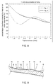
- Fig. 7 shows that, for a perfectly centered lens, changes in the ratio between optically active surface areas of near and far vision zones due to changes in pupil diameter are about the same and quite limited.
- Fig. 8 when looking at a lens with a 1 mm decentration, a worst centration normally encountered in practice , the range in which the ratio between optically active surface areas of near and far vision zones changes due to changes in pupil diameter is larger for the lens not according to the invention than for a lens according to the invention, in which the percentage of the optically active surface area covered by near or far vision zones decrease again after having increased when the pupil diameter decreases from 5 mm to 2 mm.
- the ring segments, 7, 10 in a ring inwardly of the ring segments 8, 11 bordering on the peripheral boundary 5 each bound a radially more central zone 6, 9 along a full inner circumference of that ring. This allows difference in surface level between adjacent near vision and far vision zones, and accordingly optical disturbance, to be reduced.
- each far vision one 8 of the ring segments 8, 11 bordering on the circumferential peripheral boundary 5 radially bounds a near vision ring segment 10 of a ring inwardly of the ring segments 8, 11 bordering on the peripheral boundary 5 and each near vision one 11 of the ring segments 8, 11 bordering on the circumferential peripheral boundary 5 radially bounds a far vision ring 7 segment of the ring inwardly of the ring segments 8, 11 bordering on the peripheral boundary.
- Borders 31 between most central ones 6, 9 of the near vision and far vision zones are curved with a convex side facing a center 38 of the optical portion 4 and each other, so that intersections of borders between adjacent near and far vision zones in a central portion of the optical portion 4 are avoided.
- Another advantage of this feature is that manufacturing a lens having borders between near and far vision zones passing through a center of the lens is very difficult and costly.
- Such a lens is for instance manufactured by turning, in which a lens blank is placed on a rotating machining holder and subjected to the influence of one or more material-removing tools, while the rotating lens or the tool is subjected to a to and fro movement in the direction of the axis of rotation as a function of rotation of the lens to form at least one of elevations, peripheral edge thickening or reading lens.
- the borders 31 have continuations 32, 33 extending radially towards the peripheral boundary 5 of the optical portion 4, so that borders 33 between circumferentially neighboring ones 8, 11 of the ring segments bordering on the peripheral boundary 5 are in line with borders 32 between circumferentially neighboring ones 7, 10 of the ring segments of the ring inwardly of the ring segments 8, 11 bordering on the peripheral boundary 5.
- steps between successive zones in radial direction can then be kept very small over the entire length of the border between these zones by providing that, ring segments radially bounding a more central zone are flush with the more central zone bounded thereby in at least one position along a border between that ring segment and the more central zone.
- Each next zone in radial direction can be lifted or lowered to minimize the step between the surface of that zone and the surface of the radially adjacent zone very effectively, because the level of each next vision zone has to be adapted to level one more inward vision zone only.
- a step between radially adjacent near and far vision zones can be mutually, essentially flush over the entire length of the border between these near and far vision zones by applying a surface level correction that is incrementally different for each meridian zone.
- the step between radially adjacent zones can be reduced to zero or almost zero along the entire length of the border between two of such successive zones
- the step between circumferentially adjacent near vision and far vision zones is not reduced to such an extent, because the inclination in radial direction of each near vision zones will differ significantly from the inclination in radial direction of circumferentially adjacent far vision zones.
- the surface level correction for minimizing steps between radially adjacent far and near vision zones also results in reducing the maximum step between surfaces of circumferentially adjacent near vision and far vision zones.
- This reduction can amount to reducing the maximum step to at most 1/3 of the maximum step that would be obtained if all near vision zone surfaces are part of one common near vision sphere or asphere and all far vision zone surfaces are part of a common far vision sphere or asphere arranged for minimizing the average step between adjacent near vision and far vision zone surfaces.
- the near vision zones 9-11 and the far vision zones 6-8 each occupy approximately 50% of the surface of the optical portion 4, depending on requirements of a user other ratio's between the surface area's of the near vision zones 9-11 and the far vision zones 6-8 may be provided as well. In most cases, it is preferred that the near vision zones form at least 10% and at most 50% of the surface area of the optical portion 4, since good far vision in low light conditions is usually held to be more important than good near vision in low light conditions.
- Each zone 6-11 may have an aspheric correction matching the position of that zone in the optical portion 4.
- all zones 6-11 of the anterior surface of the optical portion 4 are aspheric to correct for spherical aberrations, while the posterior surface of the optical portion 4 is of a uniformly spherical shape. It is however also possible to include some or all aspherity in the uniformly shaped surface opposite the surface in which the zones with different refractive powers are formed. Also, the zones with different refractive powers may be provided by shaping such zones partially in the anterior and partially in the posterior surfaces.
- the lens 1 has a non-optical portion 18 peripherally bounding the optical portion 4.
- the non-optical portion 18 supports the optical portion, which is particularly relevant for keeping the optical portion 4 plane if the lens 1 is of the folding type so that also the optical portion 4 is of very flexible material.
- the non optical portion of the lens body may be of a light absorbing tint, color and/or texture, to avoid optical disturbance by light reflected therefrom.
- zones for enhancing vision at intermediate distances may be provided and alternate with the near and far vision zones in circumferential and radial sense.
- the near and far vision zones may be arranged in an interchanged fashion, so that in any of the embodiments all zones forming near vision zones are replaced by far vision zones and vice versa.
- FIG. 2 an optical portion 54 of a second example of a lens according to the invention is shown.
- the number of successive near and far vision zones in radial sense has been increased from two rings of circumferentially alternating near and far vision ring segment zones to five rings of circumferentially alternating near vision ring segment zones 63-67 and far vision ring segment zones 57-61.
- Within the inner ring of alternating ring segments 57, 63, central far vision ring segment zones 56 and central near vision zone 62 are arranged.
- FIG. 3 an optical portion 104 of a third example of a lens according to the invention is shown.
- the size in circumferential sense of the near vision ring segment zones 110, 111 in the rings of circumferentially alternating near and far vision ring segment zones 107, 108, 110, 111 has been reduced, so that the portion of the effective optical surface occupied by the near vision zones 109, 110, 111 reduces as the diameter of the area of the optical portion 104 that is effective increases with the pupil diameter.
- the pupil diameter tends to increase as ambient light intensity becomes lower.
- the proportion of the surface area available for far vision enhancement increases as light levels are lower and far vision becomes more important, for instance when walking in the dark or driving at night.
- An increase or decrease of the portion of the effective optical surface occupied by the near vision zones as the diameter of the area of the optical portion that is effective increases with the pupil diameter can also be achieved by arranging borders between radially adjacent far and near vision zones more inwardly or more outwardly.
- borders 133 between circumferentially adjacent far vision zones 108 and near vision zones 111 in the ring bordering the peripheral boundary 105 of the optical portion 104 are not in line with the borders 132 between circumferentially adjacent far vision zones 107 and near vision zones 110 in the ring inwardly bordering on the ring bordering the peripheral boundary 105 of the optical portion 104.
- These more inward borders 132 are also not in line with the boundary 131 between the most central far vision zones 106 and near vision zone 109.
- the lens according to Fig. 3 has more intersections of borders between adjacent vision zones and relatively large steps may occur at the borders between radially adjacent far vision zones 106, 107, 108.
- the non-circular shapes formed by the circumferentially contiguous borders 184-187 are oval, which is advantageous for keeping the overall length of the borders 184-187 low.
- a particularly small overall length of these borders 184-187 has been achieved in the present example by providing the non-circular shapes in the form of ellipsoids.
- two sets of circumferentially contiguous borders 184, 185 and 186, 187 have been provided, the longitudinal axis of the shape formed by the first set of circumferentially contiguous borders 184, 185 being perpendicular to the longitudinal axis of the shape formed by the other set of circumferentially contiguous borders 186, 187.
Landscapes
- Health & Medical Sciences (AREA)
- Ophthalmology & Optometry (AREA)
- Physics & Mathematics (AREA)
- General Health & Medical Sciences (AREA)
- General Physics & Mathematics (AREA)
- Optics & Photonics (AREA)
- Transplantation (AREA)
- Oral & Maxillofacial Surgery (AREA)
- Cardiology (AREA)
- Engineering & Computer Science (AREA)
- Biomedical Technology (AREA)
- Heart & Thoracic Surgery (AREA)
- Vascular Medicine (AREA)
- Life Sciences & Earth Sciences (AREA)
- Animal Behavior & Ethology (AREA)
- Public Health (AREA)
- Veterinary Medicine (AREA)
- Eyeglasses (AREA)
- Prostheses (AREA)
Claims (18)
- Lentille ophtalmique multifocale destinée à être portée sur ou dans un œil humain, la lentille ayant une partie optique avec des surfaces antérieure et postérieure et une limite périphérique circonférentielle, la partie optique ayant des zones de vision de loin ayant une première puissance de réfraction et des zones de vision de près ayant une puissance d'addition, les zones de vision de loin et les zones de vision de près comportant des segments annulaires ayant l'une desdites puissances de réfraction délimitant chacun radialement une zone plus centrale d'une autre desdites puissances de réfraction, les segments annulaires comportant des segments annulaires avoisinant la limite périphérique et alternés dans le sens circonférentiel le long de la circonférence totale de la limite périphérique.
- Lentille selon la revendication 1, dans laquelle les segments annulaires dans au moins un anneau vers l'intérieur desdits segments annulaires avoisinant la limite périphérique délimitent chacun une zone radialement plus centrale le long d'une circonférence interne totale dudit anneau.
- Lentille selon la revendication 1, dans laquelle chacun des segments annulaires de vision de loin avoisinant la limite périphérique circonférentielle délimite radialement un segment annulaire de vision de près d'un anneau vers l'intérieur desdits segments annulaires avoisinant la limite périphérique et chacun des segments annulaires de vision de près avoisinant la limite périphérique circonférentielle délimite radialement un segment annulaire de vision de loin dudit anneau vers l'intérieur desdits segments annulaires avoisinant la limite périphérique.
- Lentille selon l'une quelconque des revendications précédentes, dans laquelle des bords entre celles plus centrales des zones de vision de près et de vision de loin sont incurvés avec un côté convexe faisant face au centre de la partie optique.
- Lentille selon les revendications 3 et 4, dans laquelle une bordure entre ceux voisins de manière circonférentielle des segments annulaires avoisinant la limite périphérique est en ligne avec une bordure entre ceux voisins de manière circonférentielle des segments annulaires dudit anneau vers l'intérieur desdits segments annulaires avoisinant la limite périphérique.
- Lentille selon la revendication 5, dans laquelle des bords contigus de manière circonférentielle entre des zones de vision de loin et des zones de vision de près radialement successives forment au moins une forme non circulaire, la forme non circulaire étant agencée de sorte que des zones de vision de près ou des zones de vision de loin d'un anneau de zones de segments annulaires successives de manière circonférentielle soient plus petites dans la direction radiale que des zones de vision de loin ou, respectivement, des zones de vision de près du même anneau de zones de segments annulaires successives de manière circonférentielle.
- Lentille selon la revendication 6, dans laquelle la forme non circulaire est une forme ovale.
- Lentille selon l'une quelconque des revendications précédentes, dans laquelle les zones de vision de près forment au moins 10 % et au plus 50 % de la superficie de surface optique.
- Lentille selon l'une quelconque des revendications précédentes, dans laquelle des zones de transition entre des zones de vision de près et de loin forment au plus 5 % de la superficie de surface optique.
- Lentille selon l'une quelconque des revendications précédentes, dans laquelle au moins l'un des segments annulaires délimitant radialement une zone plus centrale affleure la zone plus centrale ainsi délimitée, dans au moins une position le long d'une bordure entre ledit segment annulaire et ladite zone plus centrale.
- Lentille selon l'une quelconque des revendications précédentes, dans laquelle chaque zone a une correction asphérique correspondant à la position de cette zone dans la partie optique.
- Lentille selon l'une quelconque des revendications précédentes, comprenant en outre une partie non optique délimitant de manière périphérique la partie optique.
- Lentille selon la revendication 12, dans laquelle la partie non optique comprend des éléments haptiques destinés à suspendre la partie optique dans un œil.
- Lentille selon l'une quelconque des revendications précédentes, dans laquelle la limite périphérique circonférentielle est de forme circulaire ou ovale.
- Lentille selon l'une quelconque des revendications précédentes, dans laquelle :un premier d'un ensemble de ceux adjacents de manière circonférentielle desdits segments annulaires est d'une épaisseur variant d'une première épaisseur au niveau d'une bordure radialement interne dudit premier segment annulaire à une deuxième épaisseur au niveau d'une bordure radialement externe dudit premier segment annulaire ;un second dudit ensemble de ceux adjacents de manière circonférentielle desdits segments annulaires est d'une épaisseur variant d'une troisième épaisseur au niveau d'une bordure radialement interne dudit second segment annulaire à une quatrième épaisseur au niveau d'une bordure radialement externe dudit second segment annulaire ;la première épaisseur est inférieure à la troisième épaisseur et la deuxième épaisseur est supérieure à la quatrième épaisseur ; etles segments annulaires adjacents de manière circonférentielle dudit ensemble sont d'épaisseur égale dans une position située dans le sens radial entre les bords interne et externe dudit ensemble de segments annulaires adjacents de manière circonférentielle.
- Lentille selon la revendication 15, dans laquelle, pour au moins un autre ensemble de ceux adjacents de manière circonférentielle desdits segments annulaires, radialement adjacent audit ensemble de ceux adjacents de manière circonférentielle desdits segments annulaires :un premier de l'autre ensemble de ceux adjacents de manière circonférentielle desdits segments annulaires est d'une épaisseur variant d'une première épaisseur au niveau d'une bordure radialement interne dudit autre premier segment annulaire à une deuxième épaisseur au niveau d'une bordure radialement externe dudit autre premier segment annulaire ;un second dudit autre ensemble de ceux adjacents de manière circonférentielle desdits segments annulaires est d'une épaisseur variant d'une troisième épaisseur au niveau de la bordure radialement interne dudit autre second segment annulaire à une quatrième épaisseur au niveau d'une bordure radialement externe dudit autre second segment annulaire ;la première épaisseur est inférieure à la troisième épaisseur et la deuxième épaisseur est supérieure à la quatrième épaisseur ; etles segments annulaires adjacents de manière circonférentielle dudit autre ensemble sont d'épaisseur égale dans une position située dans le sens radial entre les bords interne et externe dudit autre ensemble de segments annulaires adjacents de manière circonférentielle.
- Lentille selon la revendication 15, dans laquelle, pour chaque ensemble de ceux adjacents de manière circonférentielle desdits segments annulaires :un premier d'un ensemble de ceux adjacents de manière circonférentielle desdits segments annulaires est d'une épaisseur variant d'une première épaisseur au niveau d'une bordure radialement interne dudit premier segment annulaire à une deuxième épaisseur au niveau d'une bordure radialement externe dudit premier segment annulaire ;un second dudit ensemble de ceux adjacents de manière circonférentielle desdits segments annulaires est d'une épaisseur variant d'une troisième épaisseur au niveau d'une bordure radialement interne dudit second segment annulaire à une quatrième épaisseur au niveau d'une bordure radialement externe dudit second segment annulaire ;la première épaisseur est inférieure à la troisième épaisseur et la deuxième épaisseur est supérieure à la quatrième épaisseur ; etles segments annulaires adjacents de manière circonférentielle dudit ensemble sont d'épaisseur égale dans une position située dans le sens radial entre les bords interne et externe dudit ensemble de segments annulaires adjacents de manière circonférentielle.
- Lentille selon l'une quelconque des revendications 15 à 17, dans laquelle des positions d'épaisseur égale de ceux adjacents de manière circonférentielle sont situées dans une zone entre 30 et 70 % et de manière davantage préférée entre 40 et 60 % de la distance entre les bords interne et externe des segments annulaires respectifs.
Priority Applications (1)
| Application Number | Priority Date | Filing Date | Title |
|---|---|---|---|
| PL15704859T PL3100101T3 (pl) | 2014-01-31 | 2015-02-02 | Wieloogniskowa soczewka okulistyczna do noszenia w lub na oku |
Applications Claiming Priority (3)
| Application Number | Priority Date | Filing Date | Title |
|---|---|---|---|
| EP14153523 | 2014-01-31 | ||
| EP14176734 | 2014-07-11 | ||
| PCT/NL2015/050067 WO2015115901A1 (fr) | 2014-01-31 | 2015-02-02 | Lentille ophtalmique multifocale a porter dans ou sur l'oeil |
Publications (2)
| Publication Number | Publication Date |
|---|---|
| EP3100101A1 EP3100101A1 (fr) | 2016-12-07 |
| EP3100101B1 true EP3100101B1 (fr) | 2019-12-11 |
Family
ID=52474053
Family Applications (1)
| Application Number | Title | Priority Date | Filing Date |
|---|---|---|---|
| EP15704859.6A Active EP3100101B1 (fr) | 2014-01-31 | 2015-02-02 | Lentille ophtalmique multifocale destinée à être portée dans ou sur l''il |
Country Status (8)
| Country | Link |
|---|---|
| US (1) | US10031347B2 (fr) |
| EP (1) | EP3100101B1 (fr) |
| KR (1) | KR102047157B1 (fr) |
| CN (1) | CN106461971B (fr) |
| ES (1) | ES2770732T3 (fr) |
| HU (1) | HUE048829T2 (fr) |
| PL (1) | PL3100101T3 (fr) |
| WO (1) | WO2015115901A1 (fr) |
Families Citing this family (10)
| Publication number | Priority date | Publication date | Assignee | Title |
|---|---|---|---|---|
| KR101870142B1 (ko) | 2016-08-12 | 2018-06-25 | 이성준 | 노안용 콘택트렌즈 |
| EP3713529B1 (fr) * | 2017-11-24 | 2025-01-08 | Université de Montréal | Méthode de fabrication d'une lentille corrective pour la gestion de croissance de la longueur axiale oculaire dans le contexte d'une évolution d'une erreur de réfraction |
| CN107728338B (zh) * | 2017-12-06 | 2024-01-26 | 爱博诺德(北京)医疗科技股份有限公司 | 角膜塑形镜 |
| WO2019109862A2 (fr) | 2017-12-06 | 2019-06-13 | 爱博诺德(北京)医疗科技有限公司 | Lentille d'orthokératologie et son procédé de fabrication |
| EP3861402A1 (fr) * | 2018-12-21 | 2021-08-11 | Alcon Inc. | Bord à courbures multiples pour lentilles ophtalmiques |
| US12105361B2 (en) * | 2020-12-18 | 2024-10-01 | Coopervision International Limited | Myopia-control contact lenses and methods relating thereto |
| MY200845A (en) * | 2021-04-29 | 2024-01-18 | Coopervision Int Ltd | Contact Lenses for use in Preventing or Slowing the Development or Progression of Myopia and Related Methods |
| MX2023011141A (es) * | 2021-04-29 | 2023-10-06 | Coopervision Int Ltd | Metodos de aumento de rotacion de lentes de contacto. |
| ES2998813T3 (en) * | 2021-04-29 | 2025-02-21 | Coopervision Int Ltd | Lens sets for use in preventing or slowing the development or progression of myopia and related methods |
| CN118871065B (zh) * | 2022-12-02 | 2025-04-08 | 深圳市新产业眼科新技术有限公司 | 具有奇异非球面锥透镜折射光学器件的增强型眼用晶状体 |
Family Cites Families (12)
| Publication number | Priority date | Publication date | Assignee | Title |
|---|---|---|---|---|
| EP0107444B1 (fr) | 1982-10-13 | 1990-06-27 | N.G. Trustees And Nominees Limited | Lentilles de contact bifocaux |
| DE3332313A1 (de) | 1983-09-07 | 1985-04-04 | Titmus Eurocon Kontaktlinsen GmbH, 8750 Aschaffenburg | Multifokale, insbesondere bifokale intraokulare kuenstliche augenlinse |
| US4898461A (en) | 1987-06-01 | 1990-02-06 | Valdemar Portney | Multifocal ophthalmic lens |
| US4906245A (en) | 1987-08-24 | 1990-03-06 | Grendahl Dennis T | Multiple element zone of focus artificial hydrogel lens |
| US5173723A (en) | 1990-10-02 | 1992-12-22 | Volk Donald A | Aspheric ophthalmic accommodating lens design for intraocular lens and contact lens |
| US5512220A (en) | 1991-07-10 | 1996-04-30 | Johnson & Johnson Vision Products, Inc. | Method of making a clear axis, segmented multifocal ophthalmic lens |
| ATE182693T1 (de) | 1995-10-31 | 1999-08-15 | Procornea Holding Bv | Multifokallinse und ihr herstellungsverfahren |
| US6790232B1 (en) | 1999-04-30 | 2004-09-14 | Advanced Medical Optics, Inc. | Multifocal phakic intraocular lens |
| WO2001018592A1 (fr) | 1999-09-03 | 2001-03-15 | John Trevor De Carle | Lentilles bifocales |
| US6986578B2 (en) | 2003-01-30 | 2006-01-17 | Johnson & Johnson Vision Care, Inc. | Multifocal ophthalmic lenses |
| US6899425B2 (en) | 2003-10-28 | 2005-05-31 | Johnson & Johnson Vision Care, Inc. | Multifocal ophthalmic lenses |
| NL2002540C2 (en) * | 2009-02-17 | 2010-08-18 | Oculentis B V | Ophthalmic lens with optical sectors. |
-
2015
- 2015-02-02 US US15/115,358 patent/US10031347B2/en active Active
- 2015-02-02 HU HUE15704859A patent/HUE048829T2/hu unknown
- 2015-02-02 WO PCT/NL2015/050067 patent/WO2015115901A1/fr not_active Ceased
- 2015-02-02 EP EP15704859.6A patent/EP3100101B1/fr active Active
- 2015-02-02 ES ES15704859T patent/ES2770732T3/es active Active
- 2015-02-02 PL PL15704859T patent/PL3100101T3/pl unknown
- 2015-02-02 KR KR1020167023948A patent/KR102047157B1/ko active Active
- 2015-02-02 CN CN201580017778.6A patent/CN106461971B/zh active Active
Non-Patent Citations (1)
| Title |
|---|
| None * |
Also Published As
| Publication number | Publication date |
|---|---|
| US10031347B2 (en) | 2018-07-24 |
| KR102047157B1 (ko) | 2019-11-20 |
| KR20160113292A (ko) | 2016-09-28 |
| CN106461971A (zh) | 2017-02-22 |
| US20170010477A1 (en) | 2017-01-12 |
| EP3100101A1 (fr) | 2016-12-07 |
| HUE048829T2 (hu) | 2020-08-28 |
| ES2770732T3 (es) | 2020-07-02 |
| PL3100101T3 (pl) | 2020-05-18 |
| WO2015115901A1 (fr) | 2015-08-06 |
| CN106461971B (zh) | 2019-06-14 |
Similar Documents
| Publication | Publication Date | Title |
|---|---|---|
| EP3100101B1 (fr) | Lentille ophtalmique multifocale destinée à être portée dans ou sur l''il | |
| CA2784794C (fr) | Lentille ophtalmique, systemes et procedes dotes d'un retard de phase variable et angulaire | |
| CA2896249C (fr) | Lentille intraoculaire multifocale refractive avec qualite optique optimisee dans une plage de focale et procede de production de celle-ci | |
| US10379379B2 (en) | Lens providing extended depth of focus and method relating to same | |
| US20210196453A1 (en) | Lenses having diffractive profiles with irregular width for vision treatment | |
| CN115697249A (zh) | 双面非球面衍射多焦点透镜及其制造和用途 | |
| US12461388B2 (en) | Multi-region refractive lenses for vision treatment | |
| US12245931B2 (en) | Achromatic lenses with zone order mixing for vision treatment | |
| US20230190452A1 (en) | Achromatic lenses for vision treatment | |
| US20250085569A1 (en) | Aspheric phase-ring structured lens designs, manufacture, and uses thereof | |
| US12544218B2 (en) | Lenses having multi-ring design for vision treatment | |
| TWI869006B (zh) | 眼科鏡片及其相關方法 | |
| CA3166123C (fr) | Verres refractifs a regions multiples pour le traitement de la vision | |
| US20230073059A1 (en) | Lenses having diffractive profiles with elevated surface roughness | |
| US12433740B2 (en) | Diffractive lenses for range of vision | |
| AU2020416508B2 (en) | Achromatic lenses with zone order mixing for vision treatment | |
| HK1262100B (en) | Ophthalmic implants with extended depth of field and enhanced distance visual acuity |
Legal Events
| Date | Code | Title | Description |
|---|---|---|---|
| PUAI | Public reference made under article 153(3) epc to a published international application that has entered the european phase |
Free format text: ORIGINAL CODE: 0009012 |
|
| STAA | Information on the status of an ep patent application or granted ep patent |
Free format text: STATUS: REQUEST FOR EXAMINATION WAS MADE |
|
| 17P | Request for examination filed |
Effective date: 20160810 |
|
| AK | Designated contracting states |
Kind code of ref document: A1 Designated state(s): AL AT BE BG CH CY CZ DE DK EE ES FI FR GB GR HR HU IE IS IT LI LT LU LV MC MK MT NL NO PL PT RO RS SE SI SK SM TR |
|
| AX | Request for extension of the european patent |
Extension state: BA ME |
|
| DAX | Request for extension of the european patent (deleted) | ||
| GRAP | Despatch of communication of intention to grant a patent |
Free format text: ORIGINAL CODE: EPIDOSNIGR1 |
|
| STAA | Information on the status of an ep patent application or granted ep patent |
Free format text: STATUS: GRANT OF PATENT IS INTENDED |
|
| INTG | Intention to grant announced |
Effective date: 20190718 |
|
| GRAS | Grant fee paid |
Free format text: ORIGINAL CODE: EPIDOSNIGR3 |
|
| GRAA | (expected) grant |
Free format text: ORIGINAL CODE: 0009210 |
|
| STAA | Information on the status of an ep patent application or granted ep patent |
Free format text: STATUS: THE PATENT HAS BEEN GRANTED |
|
| AK | Designated contracting states |
Kind code of ref document: B1 Designated state(s): AL AT BE BG CH CY CZ DE DK EE ES FI FR GB GR HR HU IE IS IT LI LT LU LV MC MK MT NL NO PL PT RO RS SE SI SK SM TR |
|
| REG | Reference to a national code |
Ref country code: GB Ref legal event code: FG4D |
|
| REG | Reference to a national code |
Ref country code: CH Ref legal event code: EP |
|
| REG | Reference to a national code |
Ref country code: AT Ref legal event code: REF Ref document number: 1212790 Country of ref document: AT Kind code of ref document: T Effective date: 20191215 |
|
| REG | Reference to a national code |
Ref country code: DE Ref legal event code: R096 Ref document number: 602015043391 Country of ref document: DE |
|
| REG | Reference to a national code |
Ref country code: IE Ref legal event code: FG4D |
|
| REG | Reference to a national code |
Ref country code: NL Ref legal event code: FP |
|
| REG | Reference to a national code |
Ref country code: LT Ref legal event code: MG4D |
|
| PG25 | Lapsed in a contracting state [announced via postgrant information from national office to epo] |
Ref country code: NO Free format text: LAPSE BECAUSE OF FAILURE TO SUBMIT A TRANSLATION OF THE DESCRIPTION OR TO PAY THE FEE WITHIN THE PRESCRIBED TIME-LIMIT Effective date: 20200311 Ref country code: LT Free format text: LAPSE BECAUSE OF FAILURE TO SUBMIT A TRANSLATION OF THE DESCRIPTION OR TO PAY THE FEE WITHIN THE PRESCRIBED TIME-LIMIT Effective date: 20191211 Ref country code: BG Free format text: LAPSE BECAUSE OF FAILURE TO SUBMIT A TRANSLATION OF THE DESCRIPTION OR TO PAY THE FEE WITHIN THE PRESCRIBED TIME-LIMIT Effective date: 20200311 Ref country code: GR Free format text: LAPSE BECAUSE OF FAILURE TO SUBMIT A TRANSLATION OF THE DESCRIPTION OR TO PAY THE FEE WITHIN THE PRESCRIBED TIME-LIMIT Effective date: 20200312 Ref country code: LV Free format text: LAPSE BECAUSE OF FAILURE TO SUBMIT A TRANSLATION OF THE DESCRIPTION OR TO PAY THE FEE WITHIN THE PRESCRIBED TIME-LIMIT Effective date: 20191211 Ref country code: FI Free format text: LAPSE BECAUSE OF FAILURE TO SUBMIT A TRANSLATION OF THE DESCRIPTION OR TO PAY THE FEE WITHIN THE PRESCRIBED TIME-LIMIT Effective date: 20191211 Ref country code: SE Free format text: LAPSE BECAUSE OF FAILURE TO SUBMIT A TRANSLATION OF THE DESCRIPTION OR TO PAY THE FEE WITHIN THE PRESCRIBED TIME-LIMIT Effective date: 20191211 |
|
| PG25 | Lapsed in a contracting state [announced via postgrant information from national office to epo] |
Ref country code: HR Free format text: LAPSE BECAUSE OF FAILURE TO SUBMIT A TRANSLATION OF THE DESCRIPTION OR TO PAY THE FEE WITHIN THE PRESCRIBED TIME-LIMIT Effective date: 20191211 Ref country code: RS Free format text: LAPSE BECAUSE OF FAILURE TO SUBMIT A TRANSLATION OF THE DESCRIPTION OR TO PAY THE FEE WITHIN THE PRESCRIBED TIME-LIMIT Effective date: 20191211 |
|
| PG25 | Lapsed in a contracting state [announced via postgrant information from national office to epo] |
Ref country code: AL Free format text: LAPSE BECAUSE OF FAILURE TO SUBMIT A TRANSLATION OF THE DESCRIPTION OR TO PAY THE FEE WITHIN THE PRESCRIBED TIME-LIMIT Effective date: 20191211 |
|
| REG | Reference to a national code |
Ref country code: ES Ref legal event code: FG2A Ref document number: 2770732 Country of ref document: ES Kind code of ref document: T3 Effective date: 20200702 |
|
| PG25 | Lapsed in a contracting state [announced via postgrant information from national office to epo] |
Ref country code: CZ Free format text: LAPSE BECAUSE OF FAILURE TO SUBMIT A TRANSLATION OF THE DESCRIPTION OR TO PAY THE FEE WITHIN THE PRESCRIBED TIME-LIMIT Effective date: 20191211 Ref country code: RO Free format text: LAPSE BECAUSE OF FAILURE TO SUBMIT A TRANSLATION OF THE DESCRIPTION OR TO PAY THE FEE WITHIN THE PRESCRIBED TIME-LIMIT Effective date: 20191211 Ref country code: EE Free format text: LAPSE BECAUSE OF FAILURE TO SUBMIT A TRANSLATION OF THE DESCRIPTION OR TO PAY THE FEE WITHIN THE PRESCRIBED TIME-LIMIT Effective date: 20191211 Ref country code: PT Free format text: LAPSE BECAUSE OF FAILURE TO SUBMIT A TRANSLATION OF THE DESCRIPTION OR TO PAY THE FEE WITHIN THE PRESCRIBED TIME-LIMIT Effective date: 20200506 |
|
| REG | Reference to a national code |
Ref country code: HU Ref legal event code: AG4A Ref document number: E048829 Country of ref document: HU |
|
| PG25 | Lapsed in a contracting state [announced via postgrant information from national office to epo] |
Ref country code: SM Free format text: LAPSE BECAUSE OF FAILURE TO SUBMIT A TRANSLATION OF THE DESCRIPTION OR TO PAY THE FEE WITHIN THE PRESCRIBED TIME-LIMIT Effective date: 20191211 Ref country code: SK Free format text: LAPSE BECAUSE OF FAILURE TO SUBMIT A TRANSLATION OF THE DESCRIPTION OR TO PAY THE FEE WITHIN THE PRESCRIBED TIME-LIMIT Effective date: 20191211 Ref country code: IS Free format text: LAPSE BECAUSE OF FAILURE TO SUBMIT A TRANSLATION OF THE DESCRIPTION OR TO PAY THE FEE WITHIN THE PRESCRIBED TIME-LIMIT Effective date: 20200411 |
|
| REG | Reference to a national code |
Ref country code: DE Ref legal event code: R097 Ref document number: 602015043391 Country of ref document: DE |
|
| REG | Reference to a national code |
Ref country code: CH Ref legal event code: PL |
|
| REG | Reference to a national code |
Ref country code: AT Ref legal event code: MK05 Ref document number: 1212790 Country of ref document: AT Kind code of ref document: T Effective date: 20191211 |
|
| PLBE | No opposition filed within time limit |
Free format text: ORIGINAL CODE: 0009261 |
|
| STAA | Information on the status of an ep patent application or granted ep patent |
Free format text: STATUS: NO OPPOSITION FILED WITHIN TIME LIMIT |
|
| PG25 | Lapsed in a contracting state [announced via postgrant information from national office to epo] |
Ref country code: DK Free format text: LAPSE BECAUSE OF FAILURE TO SUBMIT A TRANSLATION OF THE DESCRIPTION OR TO PAY THE FEE WITHIN THE PRESCRIBED TIME-LIMIT Effective date: 20191211 Ref country code: MC Free format text: LAPSE BECAUSE OF FAILURE TO SUBMIT A TRANSLATION OF THE DESCRIPTION OR TO PAY THE FEE WITHIN THE PRESCRIBED TIME-LIMIT Effective date: 20191211 Ref country code: LU Free format text: LAPSE BECAUSE OF NON-PAYMENT OF DUE FEES Effective date: 20200202 |
|
| 26N | No opposition filed |
Effective date: 20200914 |
|
| PG25 | Lapsed in a contracting state [announced via postgrant information from national office to epo] |
Ref country code: AT Free format text: LAPSE BECAUSE OF FAILURE TO SUBMIT A TRANSLATION OF THE DESCRIPTION OR TO PAY THE FEE WITHIN THE PRESCRIBED TIME-LIMIT Effective date: 20191211 Ref country code: CH Free format text: LAPSE BECAUSE OF NON-PAYMENT OF DUE FEES Effective date: 20200229 Ref country code: SI Free format text: LAPSE BECAUSE OF FAILURE TO SUBMIT A TRANSLATION OF THE DESCRIPTION OR TO PAY THE FEE WITHIN THE PRESCRIBED TIME-LIMIT Effective date: 20191211 Ref country code: LI Free format text: LAPSE BECAUSE OF NON-PAYMENT OF DUE FEES Effective date: 20200229 |
|
| PG25 | Lapsed in a contracting state [announced via postgrant information from national office to epo] |
Ref country code: IE Free format text: LAPSE BECAUSE OF NON-PAYMENT OF DUE FEES Effective date: 20200202 |
|
| PG25 | Lapsed in a contracting state [announced via postgrant information from national office to epo] |
Ref country code: MT Free format text: LAPSE BECAUSE OF FAILURE TO SUBMIT A TRANSLATION OF THE DESCRIPTION OR TO PAY THE FEE WITHIN THE PRESCRIBED TIME-LIMIT Effective date: 20191211 Ref country code: CY Free format text: LAPSE BECAUSE OF FAILURE TO SUBMIT A TRANSLATION OF THE DESCRIPTION OR TO PAY THE FEE WITHIN THE PRESCRIBED TIME-LIMIT Effective date: 20191211 |
|
| PG25 | Lapsed in a contracting state [announced via postgrant information from national office to epo] |
Ref country code: MK Free format text: LAPSE BECAUSE OF FAILURE TO SUBMIT A TRANSLATION OF THE DESCRIPTION OR TO PAY THE FEE WITHIN THE PRESCRIBED TIME-LIMIT Effective date: 20191211 |
|
| P01 | Opt-out of the competence of the unified patent court (upc) registered |
Effective date: 20240425 |
|
| PGFP | Annual fee paid to national office [announced via postgrant information from national office to epo] |
Ref country code: ES Payment date: 20250331 Year of fee payment: 11 |
|
| PGFP | Annual fee paid to national office [announced via postgrant information from national office to epo] |
Ref country code: NL Payment date: 20260218 Year of fee payment: 12 |
|
| PGFP | Annual fee paid to national office [announced via postgrant information from national office to epo] |
Ref country code: HU Payment date: 20260220 Year of fee payment: 12 |
|
| PGFP | Annual fee paid to national office [announced via postgrant information from national office to epo] |
Ref country code: GB Payment date: 20260219 Year of fee payment: 12 |
|
| PGFP | Annual fee paid to national office [announced via postgrant information from national office to epo] |
Ref country code: DE Payment date: 20260218 Year of fee payment: 12 |
|
| PGFP | Annual fee paid to national office [announced via postgrant information from national office to epo] |
Ref country code: IT Payment date: 20260224 Year of fee payment: 12 Ref country code: BE Payment date: 20260218 Year of fee payment: 12 |
|
| PGFP | Annual fee paid to national office [announced via postgrant information from national office to epo] |
Ref country code: FR Payment date: 20260218 Year of fee payment: 12 |
|
| PGFP | Annual fee paid to national office [announced via postgrant information from national office to epo] |
Ref country code: TR Payment date: 20260127 Year of fee payment: 12 |
|
| PGFP | Annual fee paid to national office [announced via postgrant information from national office to epo] |
Ref country code: PL Payment date: 20260122 Year of fee payment: 12 |