EP3100323B1 - Kontaktelement - Google Patents
Kontaktelement Download PDFInfo
- Publication number
- EP3100323B1 EP3100323B1 EP15707882.5A EP15707882A EP3100323B1 EP 3100323 B1 EP3100323 B1 EP 3100323B1 EP 15707882 A EP15707882 A EP 15707882A EP 3100323 B1 EP3100323 B1 EP 3100323B1
- Authority
- EP
- European Patent Office
- Prior art keywords
- contact
- bent part
- stop
- contact element
- punched
- Prior art date
- Legal status (The legal status is an assumption and is not a legal conclusion. Google has not performed a legal analysis and makes no representation as to the accuracy of the status listed.)
- Active
Links
Images


Classifications
-
- H—ELECTRICITY
- H01—ELECTRIC ELEMENTS
- H01R—ELECTRICALLY-CONDUCTIVE CONNECTIONS; STRUCTURAL ASSOCIATIONS OF A PLURALITY OF MUTUALLY-INSULATED ELECTRICAL CONNECTING ELEMENTS; COUPLING DEVICES; CURRENT COLLECTORS
- H01R13/00—Details of coupling devices of the kinds covered by groups H01R12/70 or H01R24/00 - H01R33/00
- H01R13/02—Contact members
- H01R13/10—Sockets for co-operation with pins or blades
- H01R13/11—Resilient sockets
- H01R13/114—Resilient sockets co-operating with pins or blades having a square transverse section
-
- H—ELECTRICITY
- H01—ELECTRIC ELEMENTS
- H01R—ELECTRICALLY-CONDUCTIVE CONNECTIONS; STRUCTURAL ASSOCIATIONS OF A PLURALITY OF MUTUALLY-INSULATED ELECTRICAL CONNECTING ELEMENTS; COUPLING DEVICES; CURRENT COLLECTORS
- H01R13/00—Details of coupling devices of the kinds covered by groups H01R12/70 or H01R24/00 - H01R33/00
- H01R13/40—Securing contact members in or to a base or case; Insulating of contact members
- H01R13/42—Securing in a demountable manner
- H01R13/428—Securing in a demountable manner by resilient locking means on the contact members; by locking means on resilient contact members
- H01R13/432—Securing in a demountable manner by resilient locking means on the contact members; by locking means on resilient contact members by stamped-out resilient tongue snapping behind shoulder in base or case
Definitions
- the invention relates to a contact element, designed as a one-piece stamped and bent part, with a latching element for fixing the contact element in a contact chamber of a connector, furthermore with a first contact spring which at least partially extends into a receiving area of the contact element for making contact with a mating contact introduced into the receiving area, according to the features of the preamble of claim 1.
- Such a generic contact element is from EP 2 193 577 B1 known.
- a metal part punched out flat with the necessary contours is used as the starting point for producing such a contact element.
- Manufacturing on the basis of such a flat structure in a stamping and bending process has the advantage that the desired geometries of the contact element for realizing its later function in the connector can be made possible very easily and, above all, economically, that is to say inexpensively in large numbers.
- the contact element Since the contact element is inserted into a contact chamber of a connector after completion and arrangement at one end of an electrical conductor (for example a punched grid, a cable or the like), it must be locked there.
- at least one lock (called primary lock) is provided by means of a latching element which is designed to be resilient.
- plug connections consisting of plug connectors and mating plug connectors that interact with them, are exposed to very high stresses in practice, especially in the automotive sector. These stresses are above all the effects of moisture, dirt, vibrations and temperature differences. These impairments often lead to difficulties in making electrical contact in the contact area, so that the required signal transmission, energy transmission or the like via the plug connection is impaired or no longer guaranteed. In the worst case, these effects on the contacts can cause electrical contact to fail completely.
- the invention is therefore based on the object of improving a known contact element that ensures stable and reliable contact over a very long period of time and that can be produced efficiently in large numbers.
- the one contact spring is assigned a second contact spring opposite, which is also formed by the stamped and bent part.
- the second contact spring advantageously increases the contact reliability, since in the event that problems should arise in the contact area between the first contact spring and the contact element resting on it, the second contact spring is also still on the mating contact that was introduced into the receiving area, is applied. This significantly increases the contact reliability, in particular with regard to the entire service life of the plug connection.
- such a contact element with two contact springs can be produced efficiently, that is to say in large numbers, very simply in that the second contact spring is also formed by the stamped and bent part, that is, the flat component in the initial state.
- the contours of the second contact spring and the connection to the base material can be easily realized using a stamping process. Once this has been done, the flat part bent in the required manner in the desired dimensions until the finished contact element is available.
- the contact element is designed in a particularly advantageous manner completely as a one-piece stamped and bent part without further parts for realizing the contact element (apart from the electrical conductor).
- the basic concept of the one-piece stamped and bent part should not be abandoned, that is, the components to be attached are only the smallest components.
- the second contact spring starts from the stamped and bent part.
- the preferably elongated second contact spring is arranged with one end on the stamped and bent part, i.e. the base body of the contact element, and protrudes into the receiving area for the mating contact so that the second contact spring is deflected when the mating contact is introduced into the receiving area , whereby a spring force acts on the mating contact.
- the second contact spring is deflected around the point at which it is arranged with its one end on the stamped and bent part. The free end can move on a circular path and be deflected in the desired manner in order to enable the mating contact to be introduced into the receiving area.
- the two ends of the second contact spring start from the stamped and bent part.
- the second contact spring which is preferably again elongated, does not have a free end, but rather the two ends are attached to the base body of the contact element, namely the stamped and bent part.
- the second contact spring extends at least partially into the receiving area for the mating contact, for example through an arc shape between the two ends, a wave shape or the like.
- the second contact spring with its two ends on the base body (Stamped and bent part) of the contact element is arranged, slightly after and thus comes to rest on the introduced mating contact, whereby a contact force is applied to the mating contact.
- the second contact spring extends from the stamped and bent part via a transverse web with at least one end, preferably with both of its ends.
- a transverse web which on the one hand is also formed by the stamped and bent part and starts from it, but on the other hand is also spaced axially from the base body (stamped and bent part), has the advantage that moving the second contact spring in the axial direction and / or transversely this can be implemented both during the introduction of the mating contact into the receiving area and afterwards.
- This movement takes place, for example, in the micrometer range and has the advantage that movements of the mating contact are cushioned via the at least one transverse web in such a way that the second contact spring is constantly in contact with the mating contact in order to advantageously achieve a relative movement between the mating contact and the second contact spring prevent.
- the latching element has a stop element which interacts with the stamped and bent part.
- This stop element present on the locking element ensures that the locking element initially protrudes as required from the stamped and bent part, i.e. the base body of the contact element, in order to come to rest in a recess in the contact chamber of the connector when it is inserted there. This means that the locking element in the direction of the base body of the contact element is deflected so that the contact element can be inserted into the contact chamber. If it is in its target position, the latching element, which was initially slightly compressed, jumps out again into the associated recess in the contact chamber in order to implement the primary locking.
- a stop element is advantageously provided on the locking element, which limits the path of the locking element in the direction of the stamped and bent part.
- the stop element of the latching element can be a separate component which is arranged on the latching element in a form-fitting and / or cohesive manner. In a particularly advantageous manner, the stop element is already produced by punching out the latching element in order to produce the flat output part of the contact element.
- the stop element interacts with the stamped and bent part via a stop.
- the stop is advantageously also formed by the stamped and bent part, but can also be a separate component to be arranged in a form-fitting and / or cohesive manner.
- the travel limit for the stop element can be set in a defined manner.
- this stop which is preferably oriented transversely to the longitudinal direction of the entire contact element, can advantageously increase the stability of the contact element.
- a free end of the first contact spring interacts with a stop of the stamped and bent part, preferably the aforementioned stop. This limits the movement of the first contact spring when the mating contact is inserted into the receiving area of the contact element.
- the contact element has at least one projection for the mating contact in its axial course of the receiving area.
- a projection it is possible to guide the mating contact in a targeted manner when it is inserted into the receiving area.
- this prevents the mating contact from coming into contact over a large area with the corresponding bearing surfaces there when it is introduced into the receiving area.
- specific contact points are defined. These contact points are largely defined by the contact surfaces of the two contact springs on the mating contact.
- the at least one projection prevents additional surfaces of the mating contact from resting against other surfaces of the receiving area of the contact element.
- the at least one projection is provided in the receiving area in front of and / or behind the contact springs.
- defined contact surfaces of the mating contact can be set in a targeted manner in the receiving area of the contact element.
- projections are particularly advantageous both in front of and behind the contact springs. It is also advantageous if these projections are provided on all four opposite surfaces of the receiving area in front of and / or behind the contact springs.
- the at least one projection is formed as a stamping through the stamped and bent part.
- the receiving area and / or a hollow chamber running parallel to the receiving area from the stamped and bent part is closed at the end.
- the front side defines the area in which the mating contact is used.
- the opening of the hollow chamber is closed on the front side. This can be done in that the closure takes place through a region of the stamped and bent part itself.
- the inlet opening of the hollow chamber can also be closed on the end face by a separate component with a form fit and / or material fit.
- the front opening of the hollow chamber can be closed in such a way that the contact chamber or the housing of the connector is inserted into the contact element, is designed in such a way that the front area of the hollow chamber is closed after the contact element has been inserted into the contact chamber becomes.
- the first embodiment is in Figures 1 to 9 and the second embodiment in FIGS Figures 10 to 14 shown.
- the contact element is provided with the reference number 1.
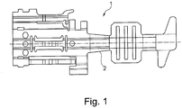
- the starting point is a flat stamped and bent part 2, which has been punched out of a suitable flat and electrically conductive material in the desired contours ( Figure 1 ).
- Figures 2 to 9 show representations of the contact element 1 after the stamping and bending process has been carried out, that is, after the in Figure 1 flat stamped and bent part 2 shown has been brought into the desired three-dimensional shape.
- the Figures 2 to 4 show, in various three-dimensional views, the contact element 1, which has crimp wings 3 and strain relief wings 4 for arrangement on an electrical conductor, not shown, of a cable in a manner known per se.
- These wings 3, 4 are present in a preferred manner, since with them a quick and efficient arrangement of the contact element 1 on the electrical conductor and thus on the cable is given.
- Alternative configurations for the arrangement of the contact element 1 at the end of the electrical conductor of the cable are thus also conceivable, so that the crimping wing 3 and the strain relief wing 4 do not necessarily have to be present, but can be replaced by other elements.
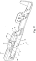
- the finished contact element 1 has a contact area 5 in the front area of its elongated extent, a latching element 6 being present there.
- This latching element 6 is formed by the stamped and bent part 2 and is resiliently arranged at a deflection point on the latter. If the contact element 1 is inserted into a contact chamber, not shown here, of the connector, the latching element 6, when viewing the Figure 2 deflected downwards so that all three surfaces O1, O2 and O3 are in one plane. After the contact element 1 has reached its final position in the contact chamber, due to a corresponding recess in the contact chamber, it is possible for the contact element 6 to deflect again, so that the surfaces O1 and O2 are still aligned, but no longer the surface O3 .
- the contact element 1 has a first contact spring 7 also formed by the stamped and bent part.
- FIG 3 it can be seen that there is a receiving area 8 in which a mating contact, not shown, is introduced. Above and running parallel to the receiving area 8, a hollow chamber 9 is formed by the stamped and bent part 2. Those areas that form the hollow chamber 9 are required in order to be able to arrange the locking element 6 here.
- first contact spring 7 In addition to the first contact spring 7, there is a second contact spring 10, which is arranged opposite the first contact spring 7.
- a stop 11 is present on the stamped and bent part 2, this stop 11 either being formed by the stamped and bent part 2 itself or a separate component which is subsequently attached to the stamped and bent part 2.
- the stop 11 cooperates with a stop element 12.
- the stop element 12 is part of the locking element 6 and is either also formed by the stamped and bent part 2 in the stamping and bending process or is a separate component which is attached to the locking element 6 is added later.
- the stop element 12 is advantageously arranged at the free end of the latching element 6 and can optionally extend beyond the free end of the latching element 6.
- the stop element 12 and the associated area of the stamped and bent part 2 are designed so that only the smallest possible free space between the free end of the latching element 6 or the stop element 12 and the adjacent fixed areas of the stamped and bent part is given.
- the reference numeral 13 denotes at least one projection which is advantageously introduced as an embossing in the stamped and bent part 2.
- opposing projections 13 are provided in the receiving area 8 in front of the contact springs 7, 10.
- these projections 13 can also be located behind the contact springs 7, 10 (that is, below the area labeled O2, see FIG Figure 2 ) are provided.
- FIG 5 it is once again particularly easy to see how the stop 11 interacts with the stop element 12 of the latching element.
- the latching element 6 protrudes from the contact element 1 in a defined manner.
- the outwardly facing surface O3 of the latching element 6 is not in one plane with the two axially surrounding surfaces O1 and O2.
- the stop element 12 is located at the level of the surface O2 in order to check that the latching element 6 is in the desired position before the contact element 1 is inserted into the contact chamber. If the contact element 1 in When the contact chamber is inserted, the latching element 6 is deflected in the direction of the receiving area 8 below it to such an extent that the three surfaces O1 to O3 are in one plane.
- the latching element 6 can be deflected back into a corresponding recess in the contact chamber, so that it is again the in Figure 5 position shown, whereby the primary locking of the contact element 1 was realized in the contact chamber.
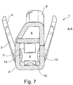
- FIG 7 a section AA in the frontal area of the contact element 1 is shown.
- the projections 13 can be seen very clearly, which protrude into the receiving area 8 and allow the mating contact inserted there to be guided in a targeted manner.
- the further elements such as crimping wing 3, strain relief wing 4 and latching element 6 indicated behind this sectional plane.
- Figure 8 shows a section BB through the contact element 1 according to Figure 5 .
- a further projection 13 can be seen very clearly in the receiving area 8, which in turn is introduced as an embossing in the stamped and bent part 2.
- the stop 11 is shown, which is also formed by the stamped and bent part 2.
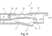
- Figure 9 finally shows a section CC through the contact element 1 according to FIG Figure 6 .
- the locking element 6 can be seen with its stop element 12, which interacts with the stop 11 (preferably formed by the stamped and bent part 2).
- a free end 14 of the first contact spring 7 also interacts with a stop, here with the stop 11.
- a targeted contact force can be set by the first contact spring 7 on the mating contact introduced into the receiving area 8.
- the stop 11 forms a travel limit both for the stop element 12 of the latching element 6 and for the free end 14 of the first contact spring 7. This enables a particularly compact design.
- both for the Provide stop element 12 as well as two separate stops for the free end 14.
- This connection of the second contact spring 10 via the at least one transverse web 15, preferably a respective transverse web 15 at the free end of the contact spring 10, has the advantage that it enables both axial movements of the contact spring 10 and movements transversely thereto.
- the cross-sectional shape of the two contact springs 7, 10 is wave-shaped in such a way that, as a result, two humps protrude in the direction of the receiving area 8, which form the contact area for the mating contact.
- a defined contact area and associated defined transition resistances can be defined.
- a relative movement between the contact area of the respective contact spring 7, 10 and the mating contact can be minimized, this being further minimized by the cardanic suspension of the at least second contact spring 10 in the stamped and bent part 2.
- the contact spring 7, 10 should be designed in its cross-section in its longitudinal course in such a way that defined contact areas are implemented and large-area contact with the mating contact is avoided.
- the in Figure 9 The undulating course of the two contact springs 7, 10 shown in cross section is of particular advantage.
- the contact spring 7 or 10 could thus also have a triangular, rectangular or comparable course or other courses.
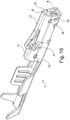
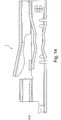
- the second exemplary embodiment differs from the first exemplary embodiment in that the stop element 12 of the latching element 6 does not protrude beyond the end face (that is, the free end) of the latching element 6, but that it is flush with the end face and in the direction of the stop 11 is arched ( Figure 11 ).
- the free element of the latching element 6 can be brought as close as possible to the adjoining part of the base body (stamped and bent part 2) so that the smallest possible gap is created between these two components in order to prevent foreign bodies (such as cables or the like) from penetrating there prevent.
- an anchor 16 is shown with which that area of the stamped and bent part 2, which forms the receiving area 8, is anchored.
- the area surrounding the receiving area 8 can also be referred to as a contact box, the at least one anchorage, preferably the two anchorages 16 shown, increasing the stability and preferably engaging in such a recess in the stamped and bent part 2 in which the area of the stamped and bent part, which forms the receiving area 8, merges into that area which forms the hollow chamber 9, which is designed as a box 17.
- a self-contained component namely the contact element 1 is formed. This closed component allows the contact element 1 to be inserted particularly easily into the contact chamber of the connector.
- the box 17 it is possible through the cross-sectional shape of the box 7 (that is, that area of the stamped and bent part 2 that surrounds the hollow chamber 9) to be specially designed in order to enable coding.
- the cross-sectional shape of the box 17 must correspond to the cross-sectional shape of the contact chamber of the connector so that the contact element 1 can even be inserted into this contact chamber of the connector. Coding over the area surrounding the receiving area 8 is not possible, since this contact area 5 with the receiving area 8 is standardized for the mating contact and thus does not allow any coding.
- the box 17 has the particular advantage that coding can be implemented with it due to its structural shape.
- the box 17 is also formed from the stamped and bent part 2, it has a material end 18 (for example in the form of a longitudinal edge) that can be supported on the corresponding area of the box around the receiving area 8. This effectively increases the stability. It can be thought of joining the material end 18 to the adjoining area of the stamped and bent part 2 in a form-fitting and / or material fit. For example, spot welding, latching or the like come into consideration here. This definition can be done in the same way as the anchoring 16.
- the stop 11 is designed as a curved tab that forms a support surface, the stop 11, in particular the curved tab, as a support surface for the adjacent latching element 6 (when viewing the Figure 10 above the stop 11) and / or the underlying contact spring 7 is used.
- this stop 11 serves as protection against overstretching of the contact locks in the form of the primary lock by means of the latching element 6.
- the stop element 12 of the stop 11 is arcuate.
- the latching element 6 has a recess 20 on the side opposite the stop element 12. This creates a material or consolidation compensation.
- An edge of the receiving area 8 is designated by 21, with the stop element 11, in particular the bent tab, coming to rest on this edge after the punching and bending process.
- the lower edge of the material end 18 of the box 7 as in FIG Figure 11 shown (left) are partially supported flat parallel on the edge 21.
- the material end 18 of the box 17 rests on a bent area of the stamped and bent part which forms the receiving area 8.
- the respective material end 18 of the box 17 can, but does not have to, be joined to the adjoining area in a form-fitting and / or material fit.
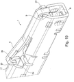
- FIG. 19 There it can be seen on the one hand that the box 17, which forms the hollow chamber 9, is closed.
- a closure 22 in the form of a bent tab of the front part of the box 17 is formed.
- This closure 22 in the form of a bent tab can, but does not have to, engage in an end-face recess of the receiving area 8.
- the lower end face of the closure 22 can also be supported on the upper side of the receiving area 8 so that it does not have to have a recess.
- the latching element 6 optionally has a hook 23 which can correspond with a recess 24 in the rear box 17. If this hook 23 is present, it can be designed in such a way that, when the surfaces O1-O3 form a continuous plane, it comes to rest on a part of the recess 24 in order to additionally or alternatively to the stop element 12 an overstretching protection of the latching element 6 to effect.
- the stop element 12 regardless of the geometry
- the hook 23 define a path limitation of the locking element 6 in order to prevent the locking element 6 from accidentally dipping too far into the box 17 or into the cavity 9. If this were the case, this would have the disadvantage that the latching element 6 can no longer be brought into a position that can be deflected sufficiently far in order to ensure primary locking in the contact chamber of the connector with it.
Landscapes
- Connector Housings Or Holding Contact Members (AREA)
- Coupling Device And Connection With Printed Circuit (AREA)
Description
- Die Erfindung betrifft ein Kontaktelement, ausgebildet als einteiliges Stanzbiegeteil, mit einem Rastelement zur Festlegung des Kontaktelementes in einer Kontaktkammer eines Steckverbinders, weiterhin mit einer ersten Kontaktfeder, die zumindest teilweise in einem Aufnahmebereich des Kontaktelementes zur Kontaktierung mit einem in den Aufnahmebereich eingeführten Gegenkontakt hineinreicht, gemäß den Merkmalen des Oberbegriffes des Patentanspruches 1.
- Ein solches gattungsgemäßes Kontaktelement ist aus der
EP 2 193 577 B1 bekannt. Als Ausgangsbasis zur Herstellung eines solchen Kontaktelementes wird ein flächig mit den erforderlichen Konturen ausgestanztes Metallteil eingesetzt. Die Herstellung auf Basis eines solchen flächigen Gebildes in einem Stanzbiegeverfahren hat den Vorteil, dass sich die gewünschten Geometrien des Kontaktelementes zur Realisierung seiner späteren Funktion in dem Steckverbinder sehr einfach und vor allen Dingen rationell, das heißt kostengünstig in hohen Stückzahlen, ermöglichen lässt. Da das Kontaktelement nach Fertigstellung und Anordnung an einem Ende eines elektrischen Leiters (zum Beispiel eines Stanzgitters, eines Kabels oder dergleichen) in eine Kontaktkammer eines Steckverbinders eingesetzt wird, muss es dort verriegelt werden. Hierzu ist zumindest eine Verriegelung (Primärverriegelung genannt) mittels eines Rastelementes, welches federnd ausgebildet ist, vorgesehen. Ein solches Rastelement ist also notwendig, genauso wie eine Kontaktfeder, die in einem Aufnahmebereich des Kontaktelementes vorgesehen ist. In den Aufnahmebereich wird ein Gegenkontakt eingeführt und somit dieser Gegenkontakt eines Gegensteckverbinders mit dem zugehörigen Kontaktelement des Steckverbinders in Wirkverbindung gebracht.DE102006006316 B3 legt einen Kontaktelement gemäß der Oberbegriff von Anspruch 1 offen. - Solche Steckverbindungen, bestehend aus Steckverbinder und damit zusammenwirkendem Gegensteckverbinder, sind in der Praxis sehr hohen Beanspruchungen, insbesondere im automotiven Bereich, ausgesetzt. Diese Beanspruchungen sind vor allen Dingen Feuchtigkeitseinflüsse, Verschmutzungen, Vibrationen und Temperaturunterschiede. Diese Beeinträchtigungen führen oftmals im Kontaktbereich zu Schwierigkeiten bei der elektrischen Kontaktierung, sodass die erforderliche Signalübertragung, Energieübertragung oder dergleichen über die Steckverbindung beeinträchtigt oder nicht mehr gewährleistet ist. Im schlimmsten Fall kann durch diese Einwirkungen auf die Kontakte eine elektrische Kontaktierung vollständig ausfallen.
- Der Erfindung liegt daher die Aufgabe zugrunde, ein bekanntes Kontaktelement dahingehend zu verbessern, das über einen sehr langen Zeitraum eine stabile und sichere Kontaktierung gewährleistet und das in hohen Stückzahlen rationell fertigbar ist.
- Diese Aufgabe ist durch die Merkmale des Patentanspruches 1 gelöst.
- Erfindungsgemäß ist vorgesehen, dass der einen Kontaktfeder gegenüberliegend eine zweite Kontaktfeder zugeordnet ist, die ebenfalls von dem Stanzbiegeteil gebildet ist. Durch die zweite Kontaktfeder wird in vorteilhafter Weise die Kontaktsicherheit erhöht, da für den Fall, dass im Kontaktbereich zwischen der ersten Kontaktfeder und dem daran anliegenden Kontaktelement Probleme auftauchen sollten, immer noch die zweite Kontaktfeder ebenfalls an dem Gegenkontakt, der in den Aufnahmebereich eingeführt wurde, anliegt. Dadurch wird die Kontaktsicherheit, insbesondere im Hinblick über die gesamte Lebensdauer der Steckverbindung, deutlich erhöht. Gleichzeitig lässt sich ein solches Kontaktelement mit zwei Kontaktfedern rationell, das heißt in hohen Stückzahlen, sehr einfach dadurch herstellen, dass die zweite Kontaktfeder ebenfalls von dem Stanzbiegeteil, das heißt, dem im Ausgangszustand flächigen Bauteil, gebildet ist. Die Konturen der zweiten Kontaktfeder und die Anbindung an das Basismaterial lassen sich einfach durch ein Stanzverfahren realisieren. Ist dies erfolgt, wird in bekannter Weise das flächige Teil in der erforderlichen Weise in den gewünschten Dimensionen gebogen, bis das fertige Kontaktelement zur Verfügung steht.
- An dieser Stelle sei erwähnt, dass das Kontaktelement in besonders vorteilhafter Weise vollständig als einteiliges Stanzbiegeteil ausgebildet ist, ohne dass weitere Teile zur Realisierung des Kontaktelementes (abgesehen von dem elektrischen Leiter) bestehen. Dem gegenüber kann daran gedacht werden, einzelne Teile als separate Bauteile auszuführen und an dem einteiligen Stanzbiegeteil form- und/oder stoffschlüssig anzuordnen. Dabei soll jedoch nicht das grundlegende Konzept des einteiligen Stanzbiegeteiles aufgegeben werden, das heißt, dass bei den anzufügenden Bauteilen es sich lediglich um kleinste Bauteile handelt.
- In Weiterbildung der Erfindung geht die zweite Kontaktfeder zumindest mit ihrem einen Ende von dem Stanzbiegeteil aus. Dadurch ist die vorzugsweise länglich ausgebildete zweite Kontaktfeder mit ihrem einen Ende an dem Stanzbiegeteil, das heißt dem Grundkörper des Kontaktelementes, angeordnet und ragt so in den Aufnahmebereich für den Gegenkontakt hinein, dass die zweite Kontaktfeder ausgelenkt wird, wenn der Gegenkontakt in den Aufnahmebereich eingeführt wird, wodurch eine Federkraft auf den Gegenkontakt einwirkt. Dies wird dadurch möglich, dass die zweite Kontaktfeder um den Punkt, an dem sie mit ihrem einen Ende an dem Stanzbiegeteil angeordnet ist, ausgelenkt wird. Dabei kann das freie Ende sich auf einer Kreisbahn bewegen und in der gewünschten Weise ausgelenkt werden, um ein Einführen des Gegenkontaktes in den Aufnahmebereich zu ermöglichen.
- In einer weiteren Ausgestaltung der Erfindung geht die zweite Kontaktfeder mit ihren beiden Enden von dem Stanzbiegeteil aus. Das bedeutet, dass die vorzugsweise wieder länglich gestaltete zweite Kontaktfeder kein freies Ende aufweist, sondern die beiden Enden an dem Grundkörper des Kontaktelementes, nämlich dem Stanzbiegeteil, befestigt ist. Um diese zweite Kotaktfeder zur Anlage an den Gegenkontakt zu bringen, ist es erforderlich, dass die zweite Kontaktfeder zum Beispiel durch eine Bogenform zwischen den beiden Enden, einer Wellenform oder dergleichen zumindest teilweise in den Aufnahmebereich für den Gegenkontakt hineinreicht. Wird der Gegenkontakt in den Aufnahmebereich eingeführt, gibt die zweite Kontaktfeder, die mit ihren beiden Enden an dem Grundkörper (Stanzbiegeteil) des Kontaktelementes angeordnet ist, geringfügig nach und kommt so zur Anlage an den eingeführten Gegenkontakt, wobei dadurch eine Kontaktkraft auf den Gegenkontakt aufgebracht wird.
- Für den Fall, dass die zweite Kontaktfeder mit ihren beiden Enden von dem Stanzbiegeteil ausgeht, ist in Weiterbildung der Erfindung vorgesehen, dass die zweite Kontaktfeder mit ihrem zumindest einen, vorzugsweise mit ihren beiden Enden, über einen Quersteg von dem Stanzbiegeteil ausgeht. Ein solcher Quersteg, der einerseits ebenfalls von dem Stanzbiegeteil gebildet ist und von diesem ausgeht, andererseits aber auch in seinem axialen Verlauf beabstandet ist von dem Grundkörper (Stanzbiegeteil), hat den Vorteil, dass ein Bewegen der zweiten Kontaktfeder in axialer Richtung und/oder quer dazu sowohl während des Einführens des Gegenkontaktes in den Aufnahmebereich als auch danach realisierbar ist. Diese Bewegung findet beispielweise im Mikrometerbereich statt und hat den Vorteil, dass Bewegungen des Gegenkontaktes derart über den zumindest einen Quersteg abgefedert werden, dass die zweite Kontaktfeder ständig an dem Gegenkontakt anliegt, um so in vorteilhafter Weise eine Relativbewegung zwischen dem Gegenkontakt und der zweiten Kontaktfeder zu verhindern. Das bedeutet, dass zwischen dem Kontaktelement, genauer dem Stanzbiegeteil, und dem Gegenkontakt im Einsatz der Steckverbindung zwar eine Relativbewegung möglich ist, diese durch die federnde Aufhängung der zweiten Kontaktfeder über den zumindest einen Quersteg jedoch verhindert wird, sodass zwischen Gegenkontakt und Kontaktfeder keine Relativbewegung erfolgt.
- Die vorstehend beschriebenen Ausführungen bezüglich der zweiten Kontaktfeder können, müssen aber nicht, auch auf die erste Kontaktfeder anwendbar sein.
- In Weiterbildung der Erfindung weist das Rastelement ein mit dem Stanzbiegeteil zusammenwirkendes Anschlagelement auf. Durch dieses an dem Rastelement vorhandene Anschlagelement wird gewährleistet, dass das Rastelement zunächst in erforderlicher Weise von dem Stanzbiegeteil, das heißt dem Grundkörper des Kontaktelementes, absteht, um in einer Ausnehmung in der Kontaktkammer des Steckverbinders zur Anlage zu kommen, wenn es dort eingesetzt wird. Das bedeutet, dass das Rastelement in Richtung des Grundkörpers des Kontaktelementes ausgelenkt wird, damit das Kontaktelement in die Kontaktkammer eingesetzt werden kann. Ist es in seiner Sollposition, springt das Rastelement, welches zunächst leicht zusammengedrückt wurde, wieder hervor in die zugehörige Ausnehmung in der Kontaktkammer, um die Primärverriegelung zu realisieren. Um zu verhindern, dass das Rastelement vor dem Einsetzen in die Kontaktkammer in unzulässiger Weise in Richtung des Grundkörpers ausgelenkt wird, ist in vorteilhafter Weise ein Anschlagelement an dem Rastelement vorhanden, welches den Weg des Rastelementes in Richtung des Stanzbiegeteiles begrenzt. Das Anschlagelement des Rastelementes kann ein separates Bauteil sein, welches form- und/oder stoffschlüssig an dem Rastelement angeordnet wird. In besonders vorteilhafter Weise wird das Anschlagelement schon mit Ausstanzen des Rastelementes zur Realisierung des flächigen Ausgangsteiles des Kontaktelementes hergestellt.
- In Weiterbildung der Erfindung wirkt das Anschlagelement über einen Anschlag mit dem Stanzbiegeteil zusammen. Der Anschlag wird in vorteilhafter Weise ebenfalls von dem Stanzbiegeteil gebildet, kann aber auch ein separates form- und/oder stoffschlüssig anzuordnendes separates Bauteil sein. Durch diesen zusätzlichen Anschlag kann die Wegebegrenzung für das Anschlagelement in definierter Weise eingestellt werden. Außerdem lässt sich über diesen Anschlag, der vorzugsweise quer zur Längsrichtung des gesamten Kontaktelementes ausgerichtet ist, die Stabilität des Kontaktelementes in vorteilhafter Weise erhöhen.
- In Weiterbildung der Erfindung wirkt ein freies Ende der ersten Kontaktfeder mit einem Anschlag des Stanzbiegeteiles, vorzugsweise dem vorgenannten Anschlag, zusammen. Hierdurch wird die Bewegung der ersten Kontaktfeder beim Einsetzen des Gegenkontaktes in den Aufnahmebereich des Kontaktelementes begrenzt. Außerdem wird vor dem Einsetzen des Kontaktelementes in die Kontaktkammer in vorteilhafter Weise wirksam verhindert, dass durch unachtsames Handling des Kontaktelementes das freie Ende der ersten Kontaktfeder unzulässig weit in den Aufnahmebereich des Kontaktelementes hineinbewegt wird. Wäre dies der Fall, wären unzulässig hohe Einführkräfte für den Gegenkontakt in den Aufnahmebereich erforderlich.
- Gemäß der Erfindung weist das Kontaktelement in seinem axialen Verlauf des Aufnahmebereiches zumindest einen Vorsprung für den Gegenkontakt auf. Mit einem solchen Vorsprung ist es möglich, den Gegenkontakt beim Einsetzen in den Aufnahmebereich gezielt zu Führen. Außerdem wird dadurch verhindert, dass der Gegenkontakt nicht großflächig beim Einführen in den Aufnahmebereich mit den dortigen korrespondierenden Auflageflächen in Berührung kommt. Denn im Hinblick auf die Langlebigkeit der elektrischen Kontaktierung ist es wichtig, dass gezielte Kontaktstellen definiert sind. Diese Kontaktstellen werden weitestgehend durch die Anlageflächen der beiden Kontaktfedern an den Gegenkontakt definiert. Eine Anlage weiterer Flächen des Gegenkontaktes an andere Flächen des Aufnahmebereiches des Kontaktelementes wird somit durch den zumindest einen Vorsprung vermieden. Zur weiteren Verbesserung der definierten Anlagekontaktflächen ist vorgesehen, dass der zumindest eine Vorsprung in dem Aufnahmebereich vor und/oder hinter den Kontaktfedern vorgesehen ist. Dadurch lassen sich, abgesehen von den Anlageflächen des Gegenkontaktes an den Kontaktfedern, definierte Anlageflächen des Gegenkontaktes in dem Aufnahmebereich des Kontaktelementes gezielt einstellen. Besonders vorteilhaft sind solche Vorsprünge sowohl vor als auch hinter den Kontaktfedern. Ebenso ist es von Vorteil, wenn an allen vier gegenüberliegenden Flächen des Aufnahmebereiches vor und/oder hinter den Kontaktfedern diese Vorsprünge vorgesehen sind.
- In Weiterbildung der Erfindung ist der zumindest eine Vorsprung als Verprägung durch das Stanzbiegeteil gebildet. Dies hat den Vorteil, dass sich ein Vorsprung sehr schnell und einfach realisieren lässt, wenn er mittels einer Verprägung in das flächige Ausgangsbauteil eingebracht wird. Auch dies lässt sich, genau wie das Stanzbiegeverfahren an sich, sehr gut automatisiert realisieren, sodass dadurch eine rationelle und vor allen Dingen auch kostengünstige Fertigung gegeben ist.
- In Weiterbildung der Erfindung ist der Aufnahmebereich und/oder eine von dem Stanzbiegeteil parallel zu dem Aufnahmebereich verlaufende Hohlkammer stirnseitig verschlossen. Mit stirnseitig ist derjenige Bereich definiert, in den der Gegenkontakt eingesetzt wird. In der Praxis kann es vorkommen, dass trotz aller Präzision des Steckverbinders und auch des Gegensteckverbinders zum Beispiel aufgrund von Toleranzen oder unachtsamer Handhabung der Gegenkontakt in die Hohlkammer eingesetzt wird. Um dies zu verhindern wird stirnseitig die Öffnung der Hohlkammer verschlossen. Dies kann dadurch erfolgen, dass der Verschluss durch einen Bereich des Stanzbiegeteiles selber erfolgt. Es kann auch die Eintrittsöffnung der Hohlkammer stirnseitig durch ein separates Bauteil form- und/oder stoffschlüssig verschlossen werden. Außerdem ist ein Verschluss der stirnseitigen Öffnung der Hohlkammer in der Weise möglich, dass die Kontaktkammer bzw. das Gehäuse des Steckverbinders, in den Kontaktelement eingesetzt wird, so gestaltet ist, dass dadurch nach dem Einsetzen des Kontaktelementes in die Kontaktkammer der stirnseitige Bereich der Hohlkammer verschlossen wird.
- Zwei Ausführungsbeispiele des erfindungsgemäßen Kontaktelementes sind im Folgenden beschrieben und anhand der Figuren erläutert.
- Das erste Ausführungsbeispiel ist in den
Figuren 1 bis 9 und das zweite Ausführungsbeispiel in denFiguren 10 bis 14 dargestellt. - In den
Figuren 1 bis 9 ist, soweit im Einzelnen dargestellt, das Kontaktelement mit der Bezugsziffer 1 versehen. Ausgangspunkt ist ein flächiges Stanzbiegeteil 2, welches in den gewünschten Konturen aus einem geeigneten flächigen und elektrischen leitfähigen Material ausgestanzt worden ist (Figur 1 ). - Die folgenden
Figuren 2 bis 9 zeigen Darstellungen des Kontaktelementes 1, nachdem das Stanzbiegeverfahren ausgeführt worden ist, das heißt, nachdem das inFigur 1 gezeigte flächige Stanzbiegeteil 2 in die gewünschte dreidimensionale Form gebracht worden ist. - Die
Figuren 2 bis 4 zeigen in verschiedenen dreidimensionalen Ansichten das Kontaktelement 1, welches zur Anordnung an einem nicht dargestellten elektrischen Leiter eines Kabels in an sich bekannter Weise Crimpflügel 3 und Zugentlastungsflügel 4 aufweist. Diese Flügel 3, 4 sind in bevorzugter Weise vorhanden, da mit ihnen eine schnelle und rationelle Anordnung des Kontaktelementes 1 an den elektrischen Leiter und damit an das Kabel gegeben ist. Alternative Ausgestaltungen für die Anordnung des Kontaktelementes 1 am Ende des elektrischen Leiters des Kabels sind somit ebenfalls denkbar, sodass Crimpflügel 3 und Zugentlastungsflügel 4 nicht zwangsweise vorhanden sein müssen, sondern durch andere Elemente ersetzt werden können. - Das fertige Kontaktelement 1 weist im vorderen Bereich seiner länglichen Erstreckung einen Kontaktbereich 5 auf, wobei dort ein Rastelement 6 vorhanden ist. Dieses Rastelement 6 wird von dem Stanzbiegeteil 2 gebildet und ist federnd an einem Auslenkpunkt an diesem angeordnet. Wird das Kontaktelement 1 in eine hier nicht dargestellte Kontaktkammer des Steckverbinders eingesetzt, wird das Rastelement 6 bei Betrachtung der
Figur 2 nach unten ausgelenkt, sodass alle drei Oberflächen O1, O2 und O3 in einer Ebene sind. Nachdem das Kontaktelement 1 seine endgültige Lage in der Kontaktkammer erreicht hat, ist es aufgrund einer korrespondierenden Ausnehmung in der Kontaktkammer möglich, dass das Kontaktelement 6 wieder auslenkt, sodass die Oberflächen O1 und O2 zwar nach wie vor fluchtend sind, jedoch nicht mehr die Oberfläche O3. - Weiterhin weist das Kontaktelement 1 eine ebenfalls von dem Stanzbiegeteil gebildete erste Kontaktfeder 7 auf.
- In
Figur 3 ist erkennbar, dass ein Aufnahmebereich 8 vorhanden ist, in dem ein nicht dargestellter Gegenkontakt eingeführt wird. Oberhalb und parallel verlaufend zu dem Aufnahmebereich 8 ist eine Hohlkammer 9 von dem Stanzbiegeteil 2 gebildet. Diejenigen Bereiche, die die Hohlkammer 9 bilden, sind erforderlich, um hier das Rastelement 6 anordnen zu können. - Weiterhin ist zu der ersten Kontaktfeder 7 eine zweite Kontaktfeder 10 vorhanden, die gegenüberliegend zu der ersten Kontaktfeder 7 angeordnet ist.
- An dem Stanzbiegeteil 2 ist ein Anschlag 11 vorhanden, wobei dieser Anschlag 11 entweder von dem Stanzbiegeteil 2 selber gebildet ist oder ein separates Bauteil ist, welches an dem Stanzbiegeteil 2 nachträglich angefügt wird. Der Anschlag 11 wirkt mit einem Anschlagelement 12 zusammen. Das Anschlagelement 12 ist Bestandteil des Rastelementes 6 und wird entweder im Stanzbiegeverfahren ebenfalls von dem Stanzbiegeteil 2 gebildet oder ist ein separates Bauteil, welches an dem Rastelement 6 nachträglich angefügt wird. Das Anschlagelement 12 ist in vorteilhafter Weise an dem freien Ende des Rastelementes 6 angeordnet und kann gegebenenfalls sich über das freie Ende des Rastelementes 6 hinaus erstrecken. In besonders vorteilhafter Weise ist das Anschlagelement 12 und der zugehörige Bereich des Stanzbiegeteiles 2 (insbesondere im Bereich des Stanzbiegeteiles 2, der die Hohlkammer 9 bildet) so gestaltet, dass nur ein möglichst geringer Freiraum zwischen dem freien Ende des Rastelements 6 bzw. des Anschlagelementes 12 und den angrenzenden feststehenden Bereichen des Stanzbiegeteiles gegeben ist. Damit wird in vorteilhafter Weise ein Eindringen von Fremdkörpern verhindert (wie zum Beispiel ein Kabel, welches im Bereich der Crimpflügel 3 schon angeschlagen ist und in diesen Bereich eindringen könnte, bevor das Kontaktelement 1 in seine zugehörige Kontaktkammer eingesetzt worden ist).
- Mit der Bezugsziffer 13 ist zumindest ein Vorsprung bezeichnet, der in vorteilhafter Weise als Verprägung in dem Stanzbiegeteil 2 eingebracht ist. Wie in den
Figuren 2 bis 4 beispielsweise erkennbar ist, sind jeweils im Aufnahmebereich 8 vor den Kontaktfedern 7, 10 jeweils gegenüberliegende Vorsprünge 13 vorhanden. Diese Vorsprünge 13 können alternativ oder ergänzend auch hinter den Kontaktfedern 7, 10 (das heißt unterhalb des mit O2 bezeichneten Bereiches, sieheFigur 2 ) vorgesehen werden. - Ergänzend zu den in den
Figuren 2 bis 4 gezeigten dreidimensionalen Darstellungen des Kontaktelementes 1 wird im Folgenden auf die Schnitte durch dieses Kontaktelement in denFiguren 7 bis 9 , basierend auf denFiguren 5 und6 , verwiesen. - In
Figur 5 ist noch einmal besonders gut erkennbar, wie der Anschlag 11 mit dem Anschlagelement 12 des Rastelementes zusammenwirkt. InFigur 5 ist zunächst dargestellt, dass das Rastelement 6 von dem Kontaktelement 1 in definierter Weise absteht. Dabei ist die nach außen weisende Oberfläche O3 des Rastelementes 6 nicht in einer Ebene mit den beiden sie axial umgebenden Oberflächen O1 und O2. Das Anschlagelement 12 befindet sich auf Höhe der Oberfläche O2, um zu kontrollieren, dass sich das Rastelement 6 in der Sollposition vor dem Einsetzen des Kontaktelementes 1 in die Kontaktkammer befindet. Wird das Kontaktelement 1 in die Kontaktkammer eingesetzt, wird das Rastelement 6 in Richtung des darunter liegenden Aufnahmebereiches 8 soweit ausgelenkt, dass sich die drei Oberflächen O1 bis O3 in einer Ebene befinden. Ist das Kontaktelement 1 dann vollständig in die Kontaktkammer eingesetzt, kann das Rastelement 6 wieder in eine korrespondierende Aussparung in der Kontaktkammer zurück ausgelenkt werden, sodass es wieder die inFigur 5 gezeigte Position einnimmt, wodurch die Primärverriegelung des Kontaktelementes 1 in der Kontaktkammer realisiert wurde. - In
Figur 7 ist ein Schnitt A-A im stirnseitigen Bereich des Kontaktelementes 1 gezeigt. Hier sind sehr gut die Vorsprünge 13 erkennbar, die in den Aufnahmebereich 8 hineinragen und eine gezielte Führung des dort eingesetzten Gegenkontaktes gestatten. Lediglich der Vollständigkeit halber sind die hinter dieser Schnittebene liegenden weiteren Elemente wie Crimpflügel 3, Zugentlastungsflügel 4 und Rastelement 6 angedeutet. -
Figur 8 zeigt einen Schnitt B-B durch das Kontaktelement 1 gemäßFigur 5 . Hier ist sehr gut ein weiterer Vorsprung 13 in dem Aufnahmebereich 8 erkennbar, der wiederum als Verprägung in dem Stanzbiegeteil 2 eingebracht ist. Außerdem ist der Anschlag 11 dargestellt, der ebenfalls von dem Stanzbiegeteil 2 gebildet ist. -
Figur 9 schließlich zeigt einen Schnitt C-C durch das Kontaktelement 1 gemäßFigur 6 . In dieser Ansicht ist sehr gut erkennbar, dass sich parallel zu dem Aufnahmebereich 8 für den Gegenkontakt die Hohlkammer 9 erstreckt. Außerdem ist das Rastelement 6 mit seinem Anschlagelement 12 erkennbar, welches mit dem Anschlag 11 (vorzugsweise gebildet durch das Stanzbiegeteil 2) zusammenwirkt. In dieser Darstellung ist auch erkennbar, dass ein freies Ende 14 der ersten Kontaktfeder 7 ebenfalls mit einem Anschlag, hier mit dem Anschlag 11 zusammenwirkt. Dadurch lässt sich eine gezielte Kontaktkraft durch die erste Kontaktfeder 7 auf den in den Aufnahmebereich 8 eingeführten Gegenkontakt einstellen. In besonders vorteilhafter Weise bildet der Anschlag 11 eine Wegbegrenzung sowohl für das Anschlagelement 12 des Rastelementes 6 als auch für das freie Ende 14 der ersten Kontaktfeder 7. Dadurch ist eine besonders kompakte Bauweise möglich. Es ist jedoch auch alternativ denkbar, sowohl für das Anschlagelement 12 als auch für das freie Ende 14 zwei voneinander separate Anschläge vorzusehen. - Außerdem ist in
Figur 9 ein weiteres sehr wichtiges Detail des erfindungsgemäßen Kontaktelementes 1 zu erkennen. Hierbei handelt es sich darum, dass die zweite Kontaktfeder 10 über jeweils einen Quersteg 15 endseitig an dem Stanzbiegeteil 2 angebunden ist. Dieser Quersteg 15 ist auch in denFiguren 4 und5 sehr gut erkennbar. Wichtig ist, dass zumindest ein Ende der zweiten Kontaktfeder 10, vorzugsweise (wie in den figürlichen Darstellungen des Ausführungsbeispiels gezeigt) beide Enden der zweiten Kontaktfeder 10 über einen solchen Quersteg 15 an dem Grundkörper des Kontaktelementes 1, der von dem Stanzbiegeteil realisiert ist, angeordnet werden. Diese Anbindung der zweiten Kontaktfeder 10 über den zumindest einen Quersteg 15, vorzugsweise jeweils ein Quersteg 15 am freien Ende der Kontaktfeder 10, hat den Vorteil, dass dadurch sowohl axiale Bewegungen der Kontaktfeder 10 als auch Bewegungen quer dazu möglich sind. Dies führt zu dem ganz entscheidenden Vorteil, dass dann, nachdem der Gegenkontakt in den Aufnahmebereich 18 eingeführt und zur Anlage an die Kontaktfedern 7, 10 gekommen ist, zumindest zwischen den Anlagepunkten der Kontaktfeder 10 an den Gegenkontakt keine Relativbewegungen mehr möglich sind, auch wenn der übrige Grundkörper des Kontaktelementes 1 noch eine (wenn auch äußerst geringe) Relativbewegung zu dem Gegenkontakt ausführt. Das bedeutet, dass der Gegenkontakt quasi kardanisch in dem Kontaktelement 1 aufgehängt ist und in vorteilhafter Weise auch während des Einsatzes der Steckverbindung in der Praxis keinerlei Relativbewegungen mehr zwischen der zumindest zweiten Kontaktfeder 10 und dem Gegenkontakt möglich sind. Dies erhöht die Kontaktsicherheit ganz wesentlich. Denn jede Relativbewegung zwischen Kontaktelement und Gegenkontakt führt zu Abrieb und damit zu undefinierten Übergangswiderständen. Außerdem würde eine Relativbewegung das Eindringen von Fremdkörpern in diesen Kontaktbereich ermöglichen, was durch diese Ausgestaltung mit der Anordnung der zweiten Kontaktfeder 10 über die Querstege 15 wirksam verhindert wird. Die gleiche Anordnung, mit der die zweite Kontaktfeder 10 über die Querstege 15 an dem Grundkörper angeordnet ist, kann auch auf die erste Kontaktfeder 7 übertragen werden, muss aber nicht. - Bezüglich der Kontaktbereiche zwischen den Kontaktfedern 7, 10 und dem Gegenkontakt ist noch folgendes auszuführen. In dem ersten Ausführungsbeispiel, welches in den
Figuren 1 bis 9 gezeigt ist, ist die Querschnittsform der beiden Kontaktfedern 7, 10 derart wellenförmig, dass dadurch zwei Höcker in Richtung des Aufnahmebereiches 8 hineinragen, die den Kontaktbereich für den Gegenkontakt bilden. Hierdurch lässt sich ein definierter Kontaktbereich und damit einhergehend definierte Übergangswiderstände definieren. Außerdem lässt sich dadurch schon eine Relativbewegung zwischen dem Kontaktbereich der jeweiligen Kontaktfeder 7, 10 und dem Gegenkontakt minimieren wobei dies durch die kardanische Aufhängung der zumindest zweiten Kontaktfeder 10 in dem Stanzbiegeteil 2 noch weiter minimiert wird. Allgemein sollte die Kontaktfeder 7, 10 in ihrem Querschnitt in ihrem Längsverlauf so gestaltet werden, dass definierte Kontaktbereiche realisiert sind und eine großflächige Anlage an den Gegenkontakt vermieden wird. Daher ist der inFigur 9 im Querschnitt dargestellte wellenförmige Verlauf der beiden Kontaktfedern 7, 10 von besonderem Vorteil. Es ist jedoch auch denkbar, an Stelle von zwei Höckern jeweils einer Kontaktfeder 7, 10 auch nur einen oder auch mehr als zwei Höcker vorzusehen. Alternativ oder ergänzend sind auch andere Anlageformen im Kontaktbereich denkbar. Die Kontaktfeder 7 bzw. 10 könnte somit auch einen dreieckförmigen, rechteckförmigen oder vergleichbaren Verlauf oder andere Verläufe aufweisen. - In den
Figuren 10 bis 19 ist analog zu denFiguren 1 bis 9 ein weiteres Ausführungsbeispiel gezeigt. Im Wesentlichen unterscheidet sich das zweite Ausführungsbeispiel von dem ersten Ausführungsbeispiel dadurch, dass das Anschlagelement 12 des Rastelementes 6 nicht über die Stirnseite (das heißt das freie Ende) des Rastelementes 6 absteht, sondern dass es bündig mit der Stirnseite abschließt und in Richtung des Anschlages 11 bogenförmig gestaltet ist (Figur 11 ). Dadurch kann das freie Element des Rastelementes 6 möglichst nah an den angrenzenden Teil des Grundkörpers (Stanzbiegeteil 2) herangeführt werden, sodass sich ein möglichst kleiner Spalt zwischen diesen beiden Bauteilen einstellt, um dort ein Eindringen von Fremdkörpern (wie zum Beispiel Kabeln oder dergleichen) zu verhindern. - Im Übrigen werden mit Bezug auf die
Figuren 10 bis 19 noch die folgenden wesentlichen Details der Ausgestaltung des Kontaktelementes 1 beschrieben, wobei diese wichtigen Vorteile dieser Details auch für das Kontaktelement des ersten Ausführungsbeispiels gemäß denFiguren 1 bis 9 gilt. - In
Figur 10 ist eine Verankerung 16 gezeigt, mit der derjenige Bereich des Stanzbiegeteiles 2, der den Aufnahmebereich 8 bildet, verankert ist. Der den Aufnahmebereich 8 umgebende Bereich kann auch als Kontakt-Kasten bezeichnet werden, wobei die zumindest eine Verankerung, vorzugsweise die beiden gezeigten Verankerungen 16, die Stabilität erhöhen und vorzugsweise in eine solche Ausnehmung in dem Stanzbiegeteil 2 eingreife, in der der Bereich des Stanzbiegeteiles, der den Aufnahmebereich 8 bildet, in denjenigen Bereich übergeht, der die Hohlkammer 9 bildet, die als Kasten 17 ausgestaltet ist. Durch diese Bauform des Kastens 17 der Hohlkammer 9 wird ein in sich geschlossenes Bauteil, nämlich das Kontaktelement 1, gebildet. Durch dieses geschlossene Bauteil lässt sich das Kontaktelement 1 besonders einfach in die Kontaktkammer des Steckverbinders einführen. Außerdem ist es möglich, durch die Querschnittsform des Kastens 7 (also derjenige Bereich des Stanzbiegeteiles 2, der die Hohlkammer 9 umgibt) besonders zu gestalten, um eine Codierung zu ermöglichen. Dass heißt, dass die Querschnittsform des Kastens 17 der Querschnittsform der Kontaktkammer des Steckverbinders entsprechen muss, damit das Kontaktelement 1 überhaupt in diese Kontaktkammer des Steckverbinders eingesetzt werden kann. Eine Codierung über den Bereich, der den Aufnahmebereich 8 umgibt, ist nicht möglich, da dieser Kontaktbereich 5 mit dem Aufnahmebereich 8 für den Gegenkontakt standardisiert ist und somit keine Codierung zulässt. In Folge dessen hat der Kasten 17 den besonderen Vorteil, dass mit ihm eine Codierung aufgrund seiner Bauform realisiert werden kann. Da der Kasten 17 ebenfalls aus dem Stanzbiegeteil 2 gebildet wird, weist er ein Materialende 18 (beispielsweise in Form einer Längskante) auf, die sich an dem korrespondierenden Bereich des Kastens um den Aufnahmebereich 8 herum abstützen kann. Dadurch wird wirksam die Stabilität erhöht. Es kann daran gedacht werden, das Materialende 18 form- und/oder stoffschlüssig an den angrenzenden Bereich des Stanzbiegeteiles 2 anzufügen. Hier kommt beispielsweise eine Punktschweißung, eine Verrastung oder dergleichen in Betracht. Diese Festlegung kann in der gleichen Art erfolgen wie die Verankerung 16. Weiterhin kann derFigur 10 entnommen werden, dass der Anschlag 11 als gebogene Lasche, die eine Auflagefläche bildet, ausgeführt ist, wobei der Anschlag 11, insbesondere die gebogene Lasche, als Auflagefläche für das angrenzende Rastelement 6 (bei Betrachtung derFigur 10 oberhalb des Anschlages 11) und/oder der darunterliegenden Kontaktfeder 7 dient. Wie auch schon bezüglich des ersten Ausführungsbeispiels beschrieben dient dieser Anschlag 11 als Überdehnschutz der Kontaktverriegelungen in Form der Primärverriegelung mittels des Rastelementes 6. - Der
Figur 11 kann, wie vorstehend schon beschrieben, entnommen werden, dass das Anschlagelement 12 des Anschlages 11 bogenförmig gestaltet ist. Außerdem weist das Rastelement 6 auf der dem Anschlagelement 12 gegenüberliegenden Seite eine Ausnehmung 20 auf. Dadurch ist ein Material- bzw. Festigungsausgleich geschaffen. Mit 21 ist eine Kante des Aufnahmebereiches 8 bezeichnet, wobei an dieser Kante das Anschlagelement 11, insbesondere die gebogene Lasche, nach dem Stanzbiegeverfahren zur Anlage kommt. Außerdem kann auch die Unterkante des Materialendes 18 des Kastens 7 wie inFigur 11 gezeigt (links) teilweise sich plan parallel auf der Kante 21 abstützen. In dem rechten Bereich des Kastens 17 liegt das Materialende 18 des Kastens 17 an einem umgebogenen Bereich des Stanzbiegeteiles auf, der den Aufnahmebereich 8 bildet. Das jeweilige Materialende 18 des Kastens 17 kann, muss aber nicht, mit dem angrenzenden Bereich form- und/oder stoffschlüssig gefügt werden. - Bezüglich weiterer wichtiger Details zumindest des zweiten, gegebenenfalls des ersten Ausführungsbeispiels, wird noch auf die
Figur 19 verwiesen. Dort ist zum Einen erkennbar, dass der Kasten 17, der die Hohlkammer 9 bildet, verschlossen ist. Hier ist ein Verschluss 22 in Form einer umgebogenen Lasche des vorderen Teiles des Kastens 17 gebildet. Dieser Verschluss 22 in Form einer umgebogenen Lasche kann, muss aber nicht, in eine stirnseitige Ausnehmung des Aufnahmebereiches 8 eingreifen. Die untere Stirnseite des Verschlusses 22 kann sich auch auf der Oberseite des Aufnahmebereiches 8 abstützen, so dass dieser keine Ausnehmung aufweisen muss. - Weiterhin weist das Rastelement 6 optional einen Haken 23, der mit einer Ausnehmung 24 in dem hinteren Kasten 17 korrespondieren kann. Ist dieser Haken 23 vorhanden, kann er derart gestaltet sein, dass er dann, wenn die Oberflächen O1-O3 eine durchgehende Ebene bilden, an einem Teil der Ausnehmung 24 zur Anlage kommt, um zusätzlich oder alternativ zu dem Anschlagelement 12 einen Überdehnschutz des Rastelementes 6 zu bewirken. Dass bedeutet, dass das Anschlagelement 12 (egal welcher Geometrie) und/oder der Haken 23 eine Wegbegrenzung des Rastelementes 6 definieren, um zu verhindern, dass das Rastelement 6 versehentlich zu weit in den Kasten 17 bzw. in den Hohlraum 9 zu tief eintaucht. Wäre dies der Fall, hätte dies den Nachteil, dass das Rastelement 6 nicht mehr in eine ausreichend weitauslenkbare Position gebracht werden kann, um mit ihm die Primärverriegelung in der Kontaktkammer des Steckverbinders sicherzustellen.
-
- 1.
- Kontaktelement
- 2.
- Stanzbiegeteil
- 3.
- Crimpflügel
- 4.
- Zugentlastungsflügel
- 5.
- Kontaktbereich
- 6.
- Rastelement
- 7.
- Erste Kontaktfeder
- 8.
- Aufnahmebereich
- 9.
- Hohlkammer
- 10.
- Zweite Kontaktfeder
- 11.
- Anschlag
- 12.
- Anschlagelement
- 13.
- Vorsprung
- 14.
- Freies Ende
- 15.
- Quersteg
- 16.
- Verankerung
- 17.
- Kasten
- 18.
- Materialende
- 19.
- Materialende
- 20.
- Ausnehmung
- 21.
- Kante
- 22.
- Verschluss
- 23.
- Haken
- 24.
- Ausnehmung
Claims (10)
- Kontaktelement (1), ausgebildet als einteiliges Stanzbiegeteil (2), mit einem Rastelement (6) zur Festlegung des Kontaktelementes (1) in einer Kontaktkammer eines Steckverbinders, weiterhin mit einer ersten Kontaktfeder (7), die zumindest teilweise in einen Aufnahmebereich (8) des Kontaktelementes (1) zur Kontaktierung mit einem in den Aufnahmebereich (8) eingeführten Gegenkontakt hineinreicht, wobei der einen Kontaktfeder (7) gegenüberliegend eine zweite Kontaktfeder (10) zugeordnet ist, die ebenfalls von dem Stanzbiegeteil (2) gebildet ist, wobei das Kontaktelement (1) in seinem axialen Verlauf des Aufnahmebereiches (8) zumindest einen Vorsprung (13) für den Gegenkontakt aufweist, dadurch gekennzeichnet, dass der zumindest eine Vorsprung (13) in dem Aufnahmebereich (8) vor und/oder hinter den Kontaktfedern (7, 10) vorgesehen ist.
- Kontaktelement (1) nach Anspruch 1, dadurch gekennzeichnet, dass die zweite Kontaktfeder (10) zumindest mit ihrem einen Ende von dem Stanzbiegeteil (2) ausgeht.
- Kontaktelement (1) nach Anspruch 1, dadurch gekennzeichnet, dass die zweite Kontaktfeder (10) mit ihren beiden Enden von dem Stanzbiegeteil (2) ausgeht.
- Kontaktelement (1) nach Anspruch 2 oder 3, dadurch gekennzeichnet, dass die zweite Kontaktfeder (10) mit ihrem zumindest einen, vorzugsweise mit ihren beiden Enden, über einen Quersteg (15) von dem Stanzbiegeteil (2) ausgeht.
- Kontaktelement (1) nach einem der vorhergehenden Ansprüche, dadurch gekennzeichnet, dass das Rastelement (6) ein mit dem Stanzbiegeteil (2) zusammenwirkendes Anschlagelement (12) aufweist.
- Kontaktelement (1) nach Anspruch 5, dadurch gekennzeichnet, dass das Anschlagelement (12) über einen Anschlag (11) mit dem Stanzbiegeteil (2) zusammenwirkt.
- Kontaktelement (1) nach Anspruch 6, dadurch gekennzeichnet, dass der Anschlag (11) ein an das Stanzbiegeteil (2) fügbares separates Bauteil oder von dem Stanzbiegeteil (2) gebildet ist.
- Kontaktelement (1) nach einem der vorhergehenden Ansprüche, dadurch gekennzeichnet, dass ein freies Ende (14) der ersten Kontaktfeder (7) mit einem Anschlag des Stanzbiegeteiles (2), vorzugsweise dem Anschlag (11), zusammenwirkt.
- Kontaktelement (1) nach einem der vorhergehenden Ansprüche, dadurch gekennzeichnet, dass der zumindest eine Vorsprung (13) als Verprägung durch das Stanzbiegeteil (2) gebildet ist.
- Kontaktelement (1) nach einem der vorhergehenden Ansprüche, dadurch gekennzeichnet, dass eine von dem Stanzbiegeteil (2) gebildete parallel zu dem Aufnahmebereich (8) verlaufende Hohlkammer (9) stirnseitig verschlossen ist.
Applications Claiming Priority (3)
| Application Number | Priority Date | Filing Date | Title |
|---|---|---|---|
| DE102014201416 | 2014-01-27 | ||
| DE102014214166 | 2014-07-21 | ||
| PCT/EP2015/051614 WO2015110661A1 (de) | 2014-01-27 | 2015-01-27 | Kontaktelement |
Publications (2)
| Publication Number | Publication Date |
|---|---|
| EP3100323A1 EP3100323A1 (de) | 2016-12-07 |
| EP3100323B1 true EP3100323B1 (de) | 2020-12-23 |
Family
ID=52627167
Family Applications (1)
| Application Number | Title | Priority Date | Filing Date |
|---|---|---|---|
| EP15707882.5A Active EP3100323B1 (de) | 2014-01-27 | 2015-01-27 | Kontaktelement |
Country Status (4)
| Country | Link |
|---|---|
| EP (1) | EP3100323B1 (de) |
| DE (1) | DE102015201381A1 (de) |
| ES (1) | ES2839124T3 (de) |
| WO (1) | WO2015110661A1 (de) |
Families Citing this family (7)
| Publication number | Priority date | Publication date | Assignee | Title |
|---|---|---|---|---|
| CN108539470B (zh) * | 2018-04-18 | 2019-10-25 | 宁波晨翔电子有限公司 | 一种排母连接器 |
| US11245212B2 (en) * | 2019-08-29 | 2022-02-08 | J.S.T. Corporation | Electrical female terminal comprising a spring member |
| US11043766B2 (en) * | 2019-08-29 | 2021-06-22 | J.S.T. Corporation | Electrical male terminal, and methods for connecting thereof |
| JP7401500B2 (ja) * | 2020-10-13 | 2023-12-19 | ティーイー コネクティビティ ジャーマニー ゲゼルシャフト ミット ベシュレンクテル ハフツンク | 電気端子 |
| US12451635B2 (en) * | 2021-06-11 | 2025-10-21 | J.S.T. Corporation | Electrical female terminal |
| US11699869B2 (en) * | 2021-06-11 | 2023-07-11 | J.S.T. Corporation | Electrical female terminal |
| DE102025003304A1 (de) | 2024-10-02 | 2026-04-02 | Hirschmann Automotive Gmbh | Einteiliger mittels eines Faltvorgangs hergestellter Kontakt für einen Steckverbinder |
Citations (2)
| Publication number | Priority date | Publication date | Assignee | Title |
|---|---|---|---|---|
| WO1998016972A1 (en) * | 1996-10-15 | 1998-04-23 | United Technologies Automotive, Inc. | Electrical terminal |
| EP2852003A1 (de) * | 2013-09-18 | 2015-03-25 | Hirschmann Automotive GmbH | Kontaktelement für einen Steckverbinder |
Family Cites Families (4)
| Publication number | Priority date | Publication date | Assignee | Title |
|---|---|---|---|---|
| US4448477A (en) * | 1982-03-19 | 1984-05-15 | General Motors Corporation | Electric socket terminal |
| DE102006006316B3 (de) * | 2006-02-11 | 2007-10-31 | Tyco Electronics Amp Gmbh | Elektrischer Buchsenkontakt |
| EP1885029B1 (de) * | 2006-08-03 | 2015-03-18 | Delphi Technologies, Inc. | Elektrisches Anschlusselement |
| DE102007040937B3 (de) | 2007-08-30 | 2009-01-15 | Tyco Electronics Amp Gmbh | Elektrischer Kontakt |
-
2015
- 2015-01-27 DE DE102015201381.2A patent/DE102015201381A1/de not_active Ceased
- 2015-01-27 WO PCT/EP2015/051614 patent/WO2015110661A1/de not_active Ceased
- 2015-01-27 ES ES15707882T patent/ES2839124T3/es active Active
- 2015-01-27 EP EP15707882.5A patent/EP3100323B1/de active Active
Patent Citations (2)
| Publication number | Priority date | Publication date | Assignee | Title |
|---|---|---|---|---|
| WO1998016972A1 (en) * | 1996-10-15 | 1998-04-23 | United Technologies Automotive, Inc. | Electrical terminal |
| EP2852003A1 (de) * | 2013-09-18 | 2015-03-25 | Hirschmann Automotive GmbH | Kontaktelement für einen Steckverbinder |
Also Published As
| Publication number | Publication date |
|---|---|
| DE102015201381A1 (de) | 2015-07-30 |
| ES2839124T3 (es) | 2021-07-05 |
| EP3100323A1 (de) | 2016-12-07 |
| WO2015110661A1 (de) | 2015-07-30 |
Similar Documents
| Publication | Publication Date | Title |
|---|---|---|
| EP3100323B1 (de) | Kontaktelement | |
| DE102013223570B4 (de) | Stiftkontakt mit einem als Stanzbiegeteil gefertigten Kontaktkörper und einem massiven Kontaktstift | |
| EP2740185B1 (de) | Elektrisches kontaktelement mit rastlanze für ein steckergehäuse | |
| DE102016221351A1 (de) | Flachkontaktbuchse mit Ausleger | |
| DE19727478A1 (de) | Buchsenartige elektrische Kontaktanordnung | |
| DE102015221937B4 (de) | Rastelement eines Kontaktes mit nasenförmigem Vorsprung | |
| EP3482460B1 (de) | Elektrischer hochleistungskontakt | |
| DE102018209783B4 (de) | Anschlussverbindungsstruktur | |
| DE3242635C2 (de) | Elektrischer Steckverbinder | |
| EP1764875B1 (de) | Elektrischer Steckverbinder mit vorgespannten Kontaktlamellen | |
| EP3288121A1 (de) | Komplett abgedichteter steckverbinder mit verbesserten haltekräften | |
| EP3038213B1 (de) | Leiteranschlussklemme zum anklemmen wenigstens eines elektrischen leiters | |
| WO2018141682A1 (de) | Kontaktlamelle für ein buchsenartiges steckverbinderteil und buchsenartiges steckverbinderteil | |
| EP1587172B1 (de) | Steckbuchse zum elektrisch leitenden Verbinden mit einem Steckstift, insbesondere Flachsteckstift | |
| DE2611446A1 (de) | Elektrische anschlussvorrichtung, insbesondere fuer leiterplatten | |
| DE10248893B3 (de) | Stecker mit Halteelement | |
| DE4322790A1 (de) | Schraubklemme mit u-förmigem Klemmkörper | |
| DE102016000384B4 (de) | Mehrpoliger elektrischer Verbinder | |
| DE102014207714B4 (de) | Kontaktanordnung mit ein Formgehemme bildenden Kontaktelementen | |
| DE3827886C1 (en) | Contact element for an electrical plug connector | |
| DE102013203546B4 (de) | Buchse oder Stecker für eine Hochstromsteckverbindung mit Kontaktlamellenring mit im Querschnitt 8-förmigen Kontaktlamellen | |
| DE10147967A1 (de) | Isolierkörper | |
| DE102020102604A1 (de) | Steckverbindung mit verbessertem Verriegelungselement | |
| DE102018117612B4 (de) | Verbindungselement für Installationsschaltgeräte, mehrpolige Installationsschaltgeräteanordnung, Schaltschrank und Verfahren | |
| DE102005047360A1 (de) | Buchsenkontakt mit zusätzlich für die Kontaktlamellen vorgesehenen Spreizlamellen |
Legal Events
| Date | Code | Title | Description |
|---|---|---|---|
| PUAI | Public reference made under article 153(3) epc to a published international application that has entered the european phase |
Free format text: ORIGINAL CODE: 0009012 |
|
| STAA | Information on the status of an ep patent application or granted ep patent |
Free format text: STATUS: REQUEST FOR EXAMINATION WAS MADE |
|
| 17P | Request for examination filed |
Effective date: 20160610 |
|
| AK | Designated contracting states |
Kind code of ref document: A1 Designated state(s): AL AT BE BG CH CY CZ DE DK EE ES FI FR GB GR HR HU IE IS IT LI LT LU LV MC MK MT NL NO PL PT RO RS SE SI SK SM TR |
|
| AX | Request for extension of the european patent |
Extension state: BA ME |
|
| DAX | Request for extension of the european patent (deleted) | ||
| STAA | Information on the status of an ep patent application or granted ep patent |
Free format text: STATUS: EXAMINATION IS IN PROGRESS |
|
| 17Q | First examination report despatched |
Effective date: 20180516 |
|
| GRAP | Despatch of communication of intention to grant a patent |
Free format text: ORIGINAL CODE: EPIDOSNIGR1 |
|
| STAA | Information on the status of an ep patent application or granted ep patent |
Free format text: STATUS: GRANT OF PATENT IS INTENDED |
|
| INTG | Intention to grant announced |
Effective date: 20200707 |
|
| RIN1 | Information on inventor provided before grant (corrected) |
Inventor name: METZLER, ANDREAS |
|
| GRAS | Grant fee paid |
Free format text: ORIGINAL CODE: EPIDOSNIGR3 |
|
| GRAA | (expected) grant |
Free format text: ORIGINAL CODE: 0009210 |
|
| STAA | Information on the status of an ep patent application or granted ep patent |
Free format text: STATUS: THE PATENT HAS BEEN GRANTED |
|
| AK | Designated contracting states |
Kind code of ref document: B1 Designated state(s): AL AT BE BG CH CY CZ DE DK EE ES FI FR GB GR HR HU IE IS IT LI LT LU LV MC MK MT NL NO PL PT RO RS SE SI SK SM TR |
|
| REG | Reference to a national code |
Ref country code: GB Ref legal event code: FG4D Free format text: NOT ENGLISH |
|
| REG | Reference to a national code |
Ref country code: RO Ref legal event code: EPE |
|
| REG | Reference to a national code |
Ref country code: DE Ref legal event code: R096 Ref document number: 502015014042 Country of ref document: DE |
|
| REG | Reference to a national code |
Ref country code: AT Ref legal event code: REF Ref document number: 1348631 Country of ref document: AT Kind code of ref document: T Effective date: 20210115 |
|
| REG | Reference to a national code |
Ref country code: IE Ref legal event code: FG4D Free format text: LANGUAGE OF EP DOCUMENT: GERMAN |
|
| PG25 | Lapsed in a contracting state [announced via postgrant information from national office to epo] |
Ref country code: GR Free format text: LAPSE BECAUSE OF FAILURE TO SUBMIT A TRANSLATION OF THE DESCRIPTION OR TO PAY THE FEE WITHIN THE PRESCRIBED TIME-LIMIT Effective date: 20210324 Ref country code: RS Free format text: LAPSE BECAUSE OF FAILURE TO SUBMIT A TRANSLATION OF THE DESCRIPTION OR TO PAY THE FEE WITHIN THE PRESCRIBED TIME-LIMIT Effective date: 20201223 Ref country code: FI Free format text: LAPSE BECAUSE OF FAILURE TO SUBMIT A TRANSLATION OF THE DESCRIPTION OR TO PAY THE FEE WITHIN THE PRESCRIBED TIME-LIMIT Effective date: 20201223 Ref country code: NO Free format text: LAPSE BECAUSE OF FAILURE TO SUBMIT A TRANSLATION OF THE DESCRIPTION OR TO PAY THE FEE WITHIN THE PRESCRIBED TIME-LIMIT Effective date: 20210323 |
|
| REG | Reference to a national code |
Ref country code: NL Ref legal event code: MP Effective date: 20201223 |
|
| PG25 | Lapsed in a contracting state [announced via postgrant information from national office to epo] |
Ref country code: BG Free format text: LAPSE BECAUSE OF FAILURE TO SUBMIT A TRANSLATION OF THE DESCRIPTION OR TO PAY THE FEE WITHIN THE PRESCRIBED TIME-LIMIT Effective date: 20210323 Ref country code: SE Free format text: LAPSE BECAUSE OF FAILURE TO SUBMIT A TRANSLATION OF THE DESCRIPTION OR TO PAY THE FEE WITHIN THE PRESCRIBED TIME-LIMIT Effective date: 20201223 Ref country code: LV Free format text: LAPSE BECAUSE OF FAILURE TO SUBMIT A TRANSLATION OF THE DESCRIPTION OR TO PAY THE FEE WITHIN THE PRESCRIBED TIME-LIMIT Effective date: 20201223 |
|
| PG25 | Lapsed in a contracting state [announced via postgrant information from national office to epo] |
Ref country code: NL Free format text: LAPSE BECAUSE OF FAILURE TO SUBMIT A TRANSLATION OF THE DESCRIPTION OR TO PAY THE FEE WITHIN THE PRESCRIBED TIME-LIMIT Effective date: 20201223 Ref country code: HR Free format text: LAPSE BECAUSE OF FAILURE TO SUBMIT A TRANSLATION OF THE DESCRIPTION OR TO PAY THE FEE WITHIN THE PRESCRIBED TIME-LIMIT Effective date: 20201223 |
|
| REG | Reference to a national code |
Ref country code: ES Ref legal event code: FG2A Ref document number: 2839124 Country of ref document: ES Kind code of ref document: T3 Effective date: 20210705 |
|
| REG | Reference to a national code |
Ref country code: LT Ref legal event code: MG9D |
|
| PG25 | Lapsed in a contracting state [announced via postgrant information from national office to epo] |
Ref country code: SM Free format text: LAPSE BECAUSE OF FAILURE TO SUBMIT A TRANSLATION OF THE DESCRIPTION OR TO PAY THE FEE WITHIN THE PRESCRIBED TIME-LIMIT Effective date: 20201223 Ref country code: LT Free format text: LAPSE BECAUSE OF FAILURE TO SUBMIT A TRANSLATION OF THE DESCRIPTION OR TO PAY THE FEE WITHIN THE PRESCRIBED TIME-LIMIT Effective date: 20201223 Ref country code: SK Free format text: LAPSE BECAUSE OF FAILURE TO SUBMIT A TRANSLATION OF THE DESCRIPTION OR TO PAY THE FEE WITHIN THE PRESCRIBED TIME-LIMIT Effective date: 20201223 Ref country code: PT Free format text: LAPSE BECAUSE OF FAILURE TO SUBMIT A TRANSLATION OF THE DESCRIPTION OR TO PAY THE FEE WITHIN THE PRESCRIBED TIME-LIMIT Effective date: 20210423 Ref country code: EE Free format text: LAPSE BECAUSE OF FAILURE TO SUBMIT A TRANSLATION OF THE DESCRIPTION OR TO PAY THE FEE WITHIN THE PRESCRIBED TIME-LIMIT Effective date: 20201223 |
|
| PG25 | Lapsed in a contracting state [announced via postgrant information from national office to epo] |
Ref country code: PL Free format text: LAPSE BECAUSE OF FAILURE TO SUBMIT A TRANSLATION OF THE DESCRIPTION OR TO PAY THE FEE WITHIN THE PRESCRIBED TIME-LIMIT Effective date: 20201223 |
|
| REG | Reference to a national code |
Ref country code: CH Ref legal event code: PL |
|
| REG | Reference to a national code |
Ref country code: DE Ref legal event code: R097 Ref document number: 502015014042 Country of ref document: DE |
|
| PG25 | Lapsed in a contracting state [announced via postgrant information from national office to epo] |
Ref country code: LU Free format text: LAPSE BECAUSE OF NON-PAYMENT OF DUE FEES Effective date: 20210127 Ref country code: IS Free format text: LAPSE BECAUSE OF FAILURE TO SUBMIT A TRANSLATION OF THE DESCRIPTION OR TO PAY THE FEE WITHIN THE PRESCRIBED TIME-LIMIT Effective date: 20210423 Ref country code: MC Free format text: LAPSE BECAUSE OF FAILURE TO SUBMIT A TRANSLATION OF THE DESCRIPTION OR TO PAY THE FEE WITHIN THE PRESCRIBED TIME-LIMIT Effective date: 20201223 |
|
| REG | Reference to a national code |
Ref country code: BE Ref legal event code: MM Effective date: 20210131 |
|
| PG25 | Lapsed in a contracting state [announced via postgrant information from national office to epo] |
Ref country code: AL Free format text: LAPSE BECAUSE OF FAILURE TO SUBMIT A TRANSLATION OF THE DESCRIPTION OR TO PAY THE FEE WITHIN THE PRESCRIBED TIME-LIMIT Effective date: 20201223 |
|
| PLBE | No opposition filed within time limit |
Free format text: ORIGINAL CODE: 0009261 |
|
| STAA | Information on the status of an ep patent application or granted ep patent |
Free format text: STATUS: NO OPPOSITION FILED WITHIN TIME LIMIT |
|
| PG25 | Lapsed in a contracting state [announced via postgrant information from national office to epo] |
Ref country code: LI Free format text: LAPSE BECAUSE OF NON-PAYMENT OF DUE FEES Effective date: 20210131 Ref country code: DK Free format text: LAPSE BECAUSE OF FAILURE TO SUBMIT A TRANSLATION OF THE DESCRIPTION OR TO PAY THE FEE WITHIN THE PRESCRIBED TIME-LIMIT Effective date: 20201223 Ref country code: CH Free format text: LAPSE BECAUSE OF NON-PAYMENT OF DUE FEES Effective date: 20210131 |
|
| 26N | No opposition filed |
Effective date: 20210924 |
|
| PG25 | Lapsed in a contracting state [announced via postgrant information from national office to epo] |
Ref country code: IE Free format text: LAPSE BECAUSE OF NON-PAYMENT OF DUE FEES Effective date: 20210127 |
|
| PG25 | Lapsed in a contracting state [announced via postgrant information from national office to epo] |
Ref country code: SI Free format text: LAPSE BECAUSE OF FAILURE TO SUBMIT A TRANSLATION OF THE DESCRIPTION OR TO PAY THE FEE WITHIN THE PRESCRIBED TIME-LIMIT Effective date: 20201223 |
|
| REG | Reference to a national code |
Ref country code: AT Ref legal event code: MM01 Ref document number: 1348631 Country of ref document: AT Kind code of ref document: T Effective date: 20210127 |
|
| PG25 | Lapsed in a contracting state [announced via postgrant information from national office to epo] |
Ref country code: AT Free format text: LAPSE BECAUSE OF NON-PAYMENT OF DUE FEES Effective date: 20210127 |
|
| PG25 | Lapsed in a contracting state [announced via postgrant information from national office to epo] |
Ref country code: IS Free format text: LAPSE BECAUSE OF FAILURE TO SUBMIT A TRANSLATION OF THE DESCRIPTION OR TO PAY THE FEE WITHIN THE PRESCRIBED TIME-LIMIT Effective date: 20210423 |
|
| PG25 | Lapsed in a contracting state [announced via postgrant information from national office to epo] |
Ref country code: BE Free format text: LAPSE BECAUSE OF NON-PAYMENT OF DUE FEES Effective date: 20210131 |
|
| PG25 | Lapsed in a contracting state [announced via postgrant information from national office to epo] |
Ref country code: HU Free format text: LAPSE BECAUSE OF FAILURE TO SUBMIT A TRANSLATION OF THE DESCRIPTION OR TO PAY THE FEE WITHIN THE PRESCRIBED TIME-LIMIT; INVALID AB INITIO Effective date: 20150127 |
|
| PG25 | Lapsed in a contracting state [announced via postgrant information from national office to epo] |
Ref country code: CY Free format text: LAPSE BECAUSE OF FAILURE TO SUBMIT A TRANSLATION OF THE DESCRIPTION OR TO PAY THE FEE WITHIN THE PRESCRIBED TIME-LIMIT Effective date: 20201223 |
|
| PGFP | Annual fee paid to national office [announced via postgrant information from national office to epo] |
Ref country code: ES Payment date: 20240223 Year of fee payment: 10 |
|
| PG25 | Lapsed in a contracting state [announced via postgrant information from national office to epo] |
Ref country code: MK Free format text: LAPSE BECAUSE OF FAILURE TO SUBMIT A TRANSLATION OF THE DESCRIPTION OR TO PAY THE FEE WITHIN THE PRESCRIBED TIME-LIMIT Effective date: 20201223 |
|
| PGFP | Annual fee paid to national office [announced via postgrant information from national office to epo] |
Ref country code: RO Payment date: 20240123 Year of fee payment: 10 Ref country code: CZ Payment date: 20240118 Year of fee payment: 10 Ref country code: GB Payment date: 20240119 Year of fee payment: 10 |
|
| PGFP | Annual fee paid to national office [announced via postgrant information from national office to epo] |
Ref country code: IT Payment date: 20240129 Year of fee payment: 10 Ref country code: FR Payment date: 20240124 Year of fee payment: 10 |
|
| PG25 | Lapsed in a contracting state [announced via postgrant information from national office to epo] |
Ref country code: MT Free format text: LAPSE BECAUSE OF FAILURE TO SUBMIT A TRANSLATION OF THE DESCRIPTION OR TO PAY THE FEE WITHIN THE PRESCRIBED TIME-LIMIT Effective date: 20201223 |
|
| GBPC | Gb: european patent ceased through non-payment of renewal fee |
Effective date: 20250127 |
|
| PG25 | Lapsed in a contracting state [announced via postgrant information from national office to epo] |
Ref country code: GB Free format text: LAPSE BECAUSE OF NON-PAYMENT OF DUE FEES Effective date: 20250127 |
|
| PG25 | Lapsed in a contracting state [announced via postgrant information from national office to epo] |
Ref country code: FR Free format text: LAPSE BECAUSE OF NON-PAYMENT OF DUE FEES Effective date: 20250131 |
|
| PG25 | Lapsed in a contracting state [announced via postgrant information from national office to epo] |
Ref country code: CZ Free format text: LAPSE BECAUSE OF NON-PAYMENT OF DUE FEES Effective date: 20250127 |
|
| PG25 | Lapsed in a contracting state [announced via postgrant information from national office to epo] |
Ref country code: RO Free format text: LAPSE BECAUSE OF NON-PAYMENT OF DUE FEES Effective date: 20250127 |
|
| PG25 | Lapsed in a contracting state [announced via postgrant information from national office to epo] |
Ref country code: TR Free format text: LAPSE BECAUSE OF FAILURE TO SUBMIT A TRANSLATION OF THE DESCRIPTION OR TO PAY THE FEE WITHIN THE PRESCRIBED TIME-LIMIT Effective date: 20201223 |
|
| PG25 | Lapsed in a contracting state [announced via postgrant information from national office to epo] |
Ref country code: IT Free format text: LAPSE BECAUSE OF NON-PAYMENT OF DUE FEES Effective date: 20250127 |
|
| REG | Reference to a national code |
Ref country code: ES Ref legal event code: FD2A Effective date: 20260304 |
|
| PG25 | Lapsed in a contracting state [announced via postgrant information from national office to epo] |
Ref country code: ES Free format text: LAPSE BECAUSE OF NON-PAYMENT OF DUE FEES Effective date: 20250128 |
|
| PGFP | Annual fee paid to national office [announced via postgrant information from national office to epo] |
Ref country code: DE Payment date: 20260121 Year of fee payment: 12 |