EP3100371B1 - Procédé et système pour fournir de la diversité dans la polarisation d'antennes - Google Patents
Procédé et système pour fournir de la diversité dans la polarisation d'antennes Download PDFInfo
- Publication number
- EP3100371B1 EP3100371B1 EP14702019.2A EP14702019A EP3100371B1 EP 3100371 B1 EP3100371 B1 EP 3100371B1 EP 14702019 A EP14702019 A EP 14702019A EP 3100371 B1 EP3100371 B1 EP 3100371B1
- Authority
- EP
- European Patent Office
- Prior art keywords
- polarization
- signal
- transmitting antenna
- bits
- receiver
- Prior art date
- Legal status (The legal status is an assumption and is not a legal conclusion. Google has not performed a legal analysis and makes no representation as to the accuracy of the status listed.)
- Not-in-force
Links
Images


Classifications
-
- H—ELECTRICITY
- H04—ELECTRIC COMMUNICATION TECHNIQUE
- H04B—TRANSMISSION
- H04B7/00—Radio transmission systems, i.e. using radiation field
- H04B7/02—Diversity systems; Multi-antenna system, i.e. transmission or reception using multiple antennas
- H04B7/10—Polarisation diversity; Directional diversity
-
- H—ELECTRICITY
- H04—ELECTRIC COMMUNICATION TECHNIQUE
- H04B—TRANSMISSION
- H04B7/00—Radio transmission systems, i.e. using radiation field
- H04B7/02—Diversity systems; Multi-antenna system, i.e. transmission or reception using multiple antennas
- H04B7/04—Diversity systems; Multi-antenna system, i.e. transmission or reception using multiple antennas using two or more spaced independent antennas
- H04B7/0413—MIMO systems
-
- H—ELECTRICITY
- H04—ELECTRIC COMMUNICATION TECHNIQUE
- H04W—WIRELESS COMMUNICATION NETWORKS
- H04W72/00—Local resource management
- H04W72/50—Allocation or scheduling criteria for wireless resources
- H04W72/54—Allocation or scheduling criteria for wireless resources based on quality criteria
- H04W72/543—Allocation or scheduling criteria for wireless resources based on quality criteria based on requested quality, e.g. QoS
Definitions
- the present invention has its application within the telecommunication sector, and especially, relates to a system and method for providing spatial diversity.
- MIMO Multiple-Input Multiple-Output
- QoS Quality of Service
- SM Spatial modulation
- the bits of information are split in some blocks of information which are coded as antenna indices. The rest of bits are transmitted through those antennas that are selected previously by those split bits. Hence, the receiver can estimate the antenna indices and therefore decode those indices to bits.
- RF Radio Frequency
- dual polarized antennas traditionally used for broadcasting where subscribers only tuned a single polarization, have also been applied in MIMO scenarios since the recent studies unveil that dual-polarized MIMO is richer in terms of diversity (" Statistical Modeling of Dual-Polarized MIMO Land Mobile Satellite Channels", by A. I. Perez-Neira et al., IEEE Transactions on Communications, Vol. 58, N0. 11, pages 3077-3083, 2010 ). Additionally, the use of dual polarized antennas is increasing by the fact that new possibilities are arising and the newest standards include dual polarized MIMO, such as Digital Video Broadcasting - Next Generation Handheld (DVB-NGH).
- DVD-NGH Digital Video Broadcasting - Next Generation Handheld
- US5822429 discloses a system for preventing reception and recognition of global positioning satellite (GPS) signals from unauthorized receivers.
- This GPS (selective denial) system comprises a jamming unit for propagating jamming waveforms and at least one receiver unit for receiving GPS signals as well as the propagated jamming waveforms.
- the jamming unit comprises a transmit antenna unit for propagating a jamming waveform at two distinct polarization states, and a transmit control switching unit for controlling the sequence of the two propagated polarization states in accordance with an encryption scheme.
- the receiver unit(s) include(s) a receive antenna unit and a jamming waveform suppression unit for suppressing each polarized state of the received jamming waveforms.
- the jamming signals in their simplest form, employ a bi-polarization keying (BPK) defined as synchronously switching and radiating between two (or more) polarization states at a near 100-percent denial duty-cycle.
- BPK bi-polarization keying
- An encoded switching modulation waveform controls switching between the polarization states by using a pseudo-noise encryption technique which allows asynchronous reception, decoding and synchronization for authorized users inputting to the GPS receiver.
- the present invention solves the aforementioned problems by disclosing a method and system that applies Spatial Modulation (SM) to dual polarized communications in (mobile and fixed) satellite channels.
- SM Spatial Modulation
- PM Polarized Modulation
- the proposed solution is here entitled Polarized Modulation (PM) and exploits the SM concept but applied for the polarization instead of antennas, providing spatial diversity using a single one double-polarized antenna (i.e., in the context of this invention, spatial diversity is not the same as antenna diversity but equal to diversity in polarization).
- the present invention achieves a relevant increase of throughput in satellite communications using low complex solutions which can involve hard and soft detections of the received signal.
- the present invention only requires 0.4 dB of additional power in order to guarantee the same QoS if compared with the case where single polarization is used.
- the present invention can be applied and validated for the ETSI's satellite related standards.
- a method for providing diversity in polarization of antennas comprises the following steps:
- Another aspect of the present invention relates to a receiver for providing diversity in polarization of antennas, comprising:
- Another aspect of the present invention relates to transmitter for providing diversity in polarization of antennas, comprising a single one transmitting antenna which is double polarized for transmitting a symbol s containing b+1 bits of information to be recovered by the above defined receiver.
- a system which is integrated in a telecommunications network, e.g., a satellite communications network, for providing diversity in polarization of antennas.
- the system comprises a transmiter and receiver, as described before:
- a computer program which comprises computer program code means adapted to perform the steps of the described method when said program is run on a computer, a digital signal processor (DSP), a field-programmable gate array (FPGA), an application-specific integrated circuit (ASIC), a micro-processor, a micro-controller, or any other form of programmable hardware.
- DSP digital signal processor
- FPGA field-programmable gate array
- ASIC application-specific integrated circuit
- Figure 1 presents the architecture building blocks of a transmitter (100) performing the proposed Polarized Modulation.
- the transmitter (100) is part of a system for providing diversity in polarization of antennas, in which each symbol to be transmitted contains b + 1 bits of information (101), where b bits (102) are modulated with a constellation S and the remaining additonal bit (103), denoted as bit c , is used for polarization selection.
- bit c the remaining additonal bit
- Any kind of digital modulation as in traditional schemes can be applied to the b bits (102).
- the modulated symbol to be transmitted is denoted as s in the equations below.
- the symbol s is transmitted using one polarization or the other.
- the transmitter (100) has a single transmitting antenna (110) which is double polarized and attached to a single RF chain (111), through which the -BB- baseband signal (104) is injected in the two polarized waveforms.
- the Mapper (112) block performs all stages to produce the waveform, e.g., using QPSK symbols.
- the Unpack block (113) makes groups of b + 1 bits and extracts from each group just one bit, e.g., the first bit, which is the bit c used by the RF chain (111) to control the polarization of the transmitting antenna (110).
- the bits of information (101) are input to a coding block (114) of the transmitter (100) and the coding block (114) generates the modulated symbols s using the constellation S , e.g., BPSK, QPSK, etc.
- the constellation S e.g., BPSK, QPSK, etc.
- FIG. 2 presents the architecture building blocks of a receiver (200) forming part of the system for providing diversity in polarization of antennas, in accordance with an embodiment of the invention.
- the receiver (200) has a single receiving antenna (210) with dual polarization. Thus, a system with double polarized antennas at both sides is considered. Also, a flat communication channel between the transmitter (100) and receiver (200) of the system is assumed.
- a baseband signal (201) is extracted at the receiving side from a single RF chain (211) attached to the receiving antenna (210).
- the baseband signal (201) passes through an estimator block (212) which extracts the bit c according to a demodulation schema.
- the receiver (200) further comprises a demapper (213) block which recovers the bits b taking as an input the bit c estimated by the estimator block (212) using one of the three proposed schemes.
- the receiver (200) includes a packing block (214) for taking all the b+1 bits, bits b from the demapper (213) and the estimated bit c , in order to join them all to a single stream s which is finally decoded by a decoding block or decoder (215) to obtain the bits of information (204).
- the decoder (215) uses a modulation scheme in correspondence with the one used by the coding block (114) included in the transmitter (100, e.g., BPSK, QPSK, 8PSK, 16QAM, 64QAM, 256QAM...
- a modulation scheme in correspondence with the one used by the coding block (114) included in the transmitter (100, e.g., BPSK, QPSK, 8PSK, 16QAM, 64QAM, 256QAM...
- the proposed system is based on dual polarized antennas providing spatial diversity at transmission using a single antenna and can increase the throughput by a factor of 1 + 1/ b in low EbN0 regimes.
- the data payload at the transmitter (100) can be constructed on ground as two streams (one for each polarization) in such way that the zeroed symbols are interleaved, i.e. when the first stream contains a symbol, the second contains a zero and vice versa.
- the satellite can increase the throughput but maintaining the legacy and compatibility with previous standards.
- the receiver (200) can use a single RF chain (211) and the only requirement is the capability to switch among the polarizations faster than the symbol rate R.
- the terminal may receive the additional bit c preserving the same chain.
- the co-channels across the two polarizations of the transmitting antenna (110) are denoted as h 11 and h 22 respectively, and the cross-channels across both polarizations are denoted as h 21 and h 12 respectively.
- AWGN Additive White Gaussian Noise
- SNR signal to noise
- the additional bit c is determined by the estimator block (212) so that, once bit c is estimated, the receiver (200) can take the received signal of the estimated polarization index and process it as a Single-input Single-output (SISO) case.
- SISO Single-input Single-output
- the first approach is to apply a matched filter to the baseband signal (201) translated from the received signal in the receiving antenna (210).
- 2 1 ⁇ c s + w 1 r 2
- 2 cs + w 2 In the case where the signal is being transmitted through the first polarization, i.e., c 0, the first matched signal r 1 contains the signal plus noise and the second matched signal r 2 only receives the noise.
- the first matched signal r 1 contains only the noise and the second matched signal r 2 conveys the signal plus the noise.
- the receiver (200) is able to decode the symbol s by the decoding block (215) based on the matched signal r ⁇ +1 .
- this first approach based on channel matching is very sensitive to the accuracy of the estimation of the matched signal r ⁇ +1 . If an error occurs, the detection of symbol s fails and the remaining b bits cannot be decoded since the receiver (200) takes the matched signal r ⁇ +1 as it only would contain noise.
- the receiver (200) is able to decode the signal r from equation 14 as usually and obtain the remaining b bits.
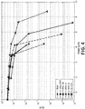
- FIGs 3 and 4 show the results of the analysis.
- PM-M is the first approach based on channel matching
- PM-H is the second approach based on likelihood ratio with hard decision
- PM-S is the third approach described based on likelihood ratio with soft decision.
- scenario H-CR which uses a higher coding rate
- Ref refers to the scenario where single polarization is used
- VBLAST Vertical Bell Laboratories Layered Space-Time
- the sampling frequency is 33600 symbols/second and the frame length is 80 ms, where the blocks of coded symbols are not interleaved. Thanks to that, it is possible to reduce the delay and offer voice traffic data in both directions.
- QPSK bearers are used for the analysis of the proposed PM approaches.
- An L-band geostationary satellite transponder with many beams and dual polarization has been simulated. Since the beams are not perfectly orthogonal, the adjacent beams have been assumed to be at the same frequency sub-band as interferences, as well as the cross polarization couplings.
- the receiver Prior to detection of symbol s , one of the three approaches (PM-M, PM-H, PM-S) are performed in order to estimate the bit c and equalize the received signal y ⁇ +1 .
- the receiver implements a Minimum Mean Square Error-MMSE- equalizer to mitigate the interferences from the other beams as well as the other polarization.
- the received signal y ⁇ +1 is equalized, it is passed to the turbo decoder and scrambler to obtain the payload in bit units. .
- the results showed that only an increment of ⁇ 0.4 dB was needed to achieve a gain of 50% of spectral efficiency.
- PM-M, PM-H and PM-S are compared also with polarization multiplexing, noted as V-BLAST, and increasing the code rate H-CR. Both prior art schemes, V-BLAST and H-CR, increase the throughput a rate by 2 and 1.4 respectively.
- Figure 3 shows that the PM approach presented here is the one that consumes less power in order to increase the throughput by 50%, since further gains cannot be achieved because the modulation used was QPSK.
- PM-S is the technique that achieves highest throughput with less EbN0, followed by PM-H. With less than 0.4dB extra, the proposed PM technique can increase the efficiency by 50% if compared with the reference scenario (Ref.) of single polarization.
Landscapes
- Engineering & Computer Science (AREA)
- Computer Networks & Wireless Communication (AREA)
- Signal Processing (AREA)
- Quality & Reliability (AREA)
- Radio Transmission System (AREA)
Claims (19)
- Procédé pour fournir une diversité de polarisation d'antennes, comprenant le fait :- d'émettre un symbole s qui contient b+1 bits d'informations par un émetteur (100),- de recevoir un signal y par un récepteur (200) qui obtient les b+1 bits d'informations à partir du signal reçu y,caractérisé en ce que :- l'émission du symbole s utilise une seule antenne d'émission (110) qui est à double polarisation et le symbole s, contenant les b bits plus un bit supplémentaire c, est émis en utilisant une première polarisation ou une deuxième polarisation de l'antenne d'émission (110) en fonction du bit supplémentaire c ;- la réception du signal y utilise une seule antenne de réception (210) qui est à double polarisation et comprend en outre le fait d'estimer le bit supplémentaire c pour déterminer si la première polarisation ou la deuxième polarisation est utilisée pour obtenir les b+1 bits d'informations.
- Procédé selon la revendication 1, dans lequel la réception du signal y comprend le fait de recevoir, par la seule antenne de réception (210), un signal de la première polarisation y1 et un signal de la deuxième polarisation y2 , qui sont
 h11 est un signal dans le même canal sur la première polarisation de l'antenne d'émission (110),h22 est un signal dans le même canal sur la deuxième polarisation de l'antenne d'émission (110),h21 est un signal entre les canaux sur la première polarisation de l'antenne d'émission (110),h12 est un signal entre les canaux sur la deuxième polarisation de l'antenne d'émission (110),w1 est un apport de bruit de la première polarisation et w2 est un apport de bruit de la deuxième polarisation,et le signal reçu y est composé du signal de la première polarisation y1 et du signal de la deuxième polarisation y2 .
 - Procédé selon la revendication 2, dans lequel les b+1 bits d'informations sont obtenus par le récepteur (200) à partir d'un signal rĉ +1 choisi entre le signal de la première polarisation y1 et le signal de la deuxième polarisation y2 qui est déterminée par un bit estimé ĉ, le bit estimé ĉ étant obtenu en estimant le bit supplémentaire c comme suit :
 où i = 1, 2 ;r1 est un premier signal adapté provenant d'un filtre adapté du récepteur (200),r2 est un deuxième signal adapté provenant du filtre adapté du récepteur (200),et si le premier signal adapté r1 est seulement du bruit, le signal choisi rĉ +1 est le deuxième signal adapté r2 ,et si le deuxième signal adapté r2 est seulement du bruit, le signal choisi rĉ +1 est le premier signal adapté r1 .
 - Procédé selon la revendication 2, dans lequel les b+1 bits d'informations sont obtenus par le récepteur (200) en utilisant un signal yĉ +1 choisi entre le signal de la première polarisation y1 et le signal de la deuxième polarisation y2 qui est déterminée par un bit estimé ĉ, le bit estimé ĉ étant obtenu en estimant le bit supplémentaire c comme suit :
 où Λ(y) est un rapport de vraisemblance d'émission avec l'une de la première polarisation et de la deuxième polarisation de l'antenne d'émission (110),et le signal choisi yĉ +1 est le signal de la deuxième polarisation y2 , si le rapport de vraisemblance Λ(y) est Λ(y) > 1 ; et sinon, le signal choisi yĉ +1 est le signal de la première polarisation y1 .
 - Procédé selon la revendication 2, dans lequel les b+1 bits d'informations sont obtenus par le récepteur (200) à partir d'un signal reçu combiné yĉ +1 en utilisant le signal de la première polarisation y1 et le signal de la deuxième polarisation y2 qui est déterminée par un bit estimé ĉ, le bit estimé étant ĉ obtenu en estimant le bit supplémentaire c comme suit :
 où Λ(y) est un rapport de vraisemblance d'émission avec l'une de la première polarisation et de la deuxième polarisation de l'antenne d'émission (110),et le signal reçu combiné yĉ +1 est calculé comme suit :
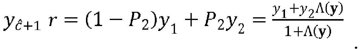
- Procédé selon l'une des revendications 4 et 5, dans lequel le rapport de vraisemblance Λ(y) est calculé comme suit :
 h1 désigne un premier vecteur de canal de coordonnées (h11, h21 ), h11, étant le signal dans le même canal sur la première polarisation de l'antenne d'émission (110) et h 21 étant le signal entre les canaux sur la première polarisation de l'antenne d'émission (110) ;h2 désigne un deuxième vecteur de canal de coordonnées (h12, h22 ), h12 étant le signal dans le même canal sur la deuxième polarisation de l'antenne d'émission (110) et h 22 est le signal entre les canaux sur la deuxième polarisation de l'antenne d'émission (110) ;σω1 est une variance de bruit de l'apport de bruit de la première polarisation w1, σω2 est une variance de bruit de l'apport de bruit de la deuxième polarisation w2 ;et S est une constellation de symboles s.
 - Système pour fournir une diversité de polarisation d'antennes, comprenant :- un émetteur (100) pour émettre un symbole s qui contient b+1 bits d'informations,- un récepteur (200) pour recevoir un signal y qui obtient les b+1 bits d'informations à partir du signal reçu y,caractérisé en ce que :- l'émetteur (100) comprend une seule antenne d'émission (110) qui est à double polarisation pour émettre le symbole s, le symbole s contenant les b bits plus un bit supplémentaire c et étant émis en utilisant une première polarisation ou une deuxième polarisation de l'antenne d'émission (110) en fonction du bit supplémentaire c ;- le récepteur (200) comprend une seule antenne de réception (210) qui est à double polarisation pour recevoir le signal y et comprend en outre un bloc estimateur (212) pour estimer le bit supplémentaire c afin de déterminer si la première polarisation ou la deuxième polarisation est utilisée pour obtenir les b+1 bits d'informations.
- Système selon la revendication 7, dans lequel la seule antenne de réception (210) est configurée pour recevoir un signal de la première polarisation y1 et un signal de la deuxième polarisation y2 , qui sont
 h11 est un signal dans le même canal sur la première polarisation de l'antenne d'émission (110),h22 est un signal dans le même canal sur la deuxième polarisation de l'antenne d'émission (110),h21 est un signal entre les canaux sur la première polarisation de l'antenne d'émission (110),h12 est un signal entre les canaux sur la deuxième polarisation de l'antenne d'émission (110),w1 est un apport de bruit de la première polarisation et w2 est un apport de bruit de la deuxième polarisation,et la seule antenne de réception (210) reçoit le signal y composé du signal de la première polarisation y1 et du signal de la deuxième polarisation y2 .
 - Système selon la revendication 8, dans lequel le récepteur (200) comprend en outre un décodeur (215) pour décoder les b+1 bits d'informations, en obtenant les b bits à partir d'un signal rĉ +1 choisi entre le signal de la première polarisation y1 et le signal de la deuxième polarisation y2 qui est déterminée par le bit supplémentaire c qui est un bit estimé ĉ obtenu par le bloc estimateur (212) comme suit :
 où i = 1, 2 ;r1 est un premier signal adapté provenant d'un filtre adapté du récepteur (200),r 2 est un deuxième signal adapté provenant du filtre adapté du récepteur (200),et si le premier signal adapté r1 est seulement du bruit, le signal choisi rĉ +1 est le deuxième signal adapté r2,et si le deuxième signal adapté r 2 est seulement du bruit, le signal choisi rĉ +1 est le premier signal adapté r1.
 - Système selon la revendication 8, dans lequel le récepteur (200) comprend en outre un décodeur (215) pour décoder les b+1 bits d'informations, en obtenant les b bits à partir d'un signal yĉ +1 choisi entre le signal de la première polarisation y1 et le signal de la deuxième polarisation y2 qui est déterminée par le bit supplémentaire c qui est un bit estimé ĉ obtenu par le bloc estimateur (212) comme suit :
 où Λ(y) est un rapport de vraisemblance d'émission avec l'une de la première polarisation et de la deuxième polarisation de l'antenne d'émission (110),et le signal choisi yĉ +1 est le signal de la deuxième polarisation y2 si le rapport de vraisemblance Λ(y) est Λ(y) > 1 ; et sinon, le signal choisi yĉ +1 est le signal de la première polarisation y1.
 - Système selon la revendication 8, dans lequel le récepteur (200) comprend en outre un décodeur (215) pour décoder les b+1 bits d'informations, en obtenant les b bits à partir d'un signal reçu combiné yĉ +1 en utilisant le signal de la première polarisation y1 et le signal de la deuxième polarisation y2 qui est déterminée par le bit supplémentaire c qui est un bit estimé ĉ obtenu par le bloc estimateur (212) comme suit :
 où Λ(y) est un rapport de vraisemblance d'émission avec l'une de la première polarisation et de la deuxième polarisation de l'antenne d'émission (110),et le signal reçu combiné yĉ +1 est calculé comme suit :
- Système selon l'une des revendications 10 et 11, dans lequel le récepteur (200) calcule le rapport de vraisemblance Λ(y) comme suit :
 h1 désigne un premier vecteur de canal de coordonnées (h 11, h 21), h 11 étant le signal dans le même canal sur la première polarisation de l'antenne d'émission (110) et h 21 étant le signal entre les canaux sur la première polarisation de l'antenne d'émission (110) ;h2 désigne un deuxième vecteur de canal de coordonnées (h 12, h22 ), h12 étant le signal dans le même canal sur la deuxième polarisation de l'antenne d'émission (110) et h 22 est le signal entre les canaux sur la deuxième polarisation de l'antenne d'émission (110) ;σω1 est une variance de bruit de l'apport de bruit de la première polarisation w1, σω2 est une variance de bruit de l'apport de bruit de la deuxième polarisation w2 ;et S est une constellation de symboles s.
 - Récepteur (200) pour fournir une diversité de polarisation d'antennes, caractérisé en ce qu'il comprend :- une seule antenne de réception (210) qui est à double polarisation pour recevoir un signal y afin d'obtenir b+1 bits d'informations à partir d'un symbole s émis par un émetteur (100), le symbole s contenant les b bits plus un bit supplémentaire c, le symbole s étant émis en utilisant une première polarisation ou une deuxième polarisation de l'antenne d'émission (110) en fonction du bit supplémentaire c,- un bloc estimateur (212) pour estimer le bit supplémentaire c afin de déterminer si une première polarisation ou une deuxième polarisation est utilisée pour obtenir les b+1 bits d'informations.
- Récepteur (200) selon la revendication 13, dans lequel la seule antenne de réception (210) est configurée pour recevoir un signal de la première polarisation y 1 et un signal de la deuxième polarisation y2 , qui sont
 h 11 est un signal dans le même canal sur la première polarisation de l'antenne d'émission (110),h 22 est un signal dans le même canal sur la deuxième polarisation de l'antenne d'émission (110),h 21 est un signal entre les canaux sur la première polarisation de l'antenne d'émission (110),h12 est un signal entre les canaux sur la deuxième polarisation de l'antenne d'émission (110),w 1 est un apport de bruit de la première polarisation et w 2 est un apport de bruit de la deuxième polarisation,et la seule antenne de réception (210) reçoit le signal y composé du signal de la première polarisation y1 et du signal de la deuxième polarisation y2 .
 - Récepteur (200) selon la revendication 14, comprenant en outre un décodeur (215) pour décoder les b+1 bits d'informations, en obtenant les b bits à partir d'un signal rĉ +1 choisi entre le signal de la première polarisation y1 et le signal de la deuxième polarisation y2 qui est déterminée par le bit supplémentaire c qui est un bit estimé ĉ obtenu par le bloc estimateur (212) comme suit :
 r1 est un premier signal adapté provenant d'un filtre adapté du récepteur (200),r 2 est un deuxième signal adapté provenant du filtre adapté du récepteur (200),et si le premier signal adapté r1 est seulement du bruit, le signal choisi rĉ +1 est le deuxième signal adapté r2,et si le deuxième signal adapté r 2 est seulement du bruit, le signal choisi rĉ +1 est le premier signal adapté r1.
 - Récepteur (200) selon la revendication 14, le récepteur (200) comprenant en outre un décodeur (215) pour décoder les b+1 bits d'informations, en obtenant les b bits à partir d'un signal yĉ+1 choisi entre le signal de la première polarisation y 1 et le signal de la deuxième polarisation y 2 qui est déterminée par le bit supplémentaire c qui est un bit estimé ĉ obtenu par le bloc estimateur (212) comme suit :
 où Λ(y) est un rapport de vraisemblance d'émission avec l'une de la première polarisation et de la deuxième polarisation de l'antenne d'émission (110),et le signal choisi yĉ+1 est le signal de la deuxième polarisation y2 si le rapport de vraisemblance Λ(y) est Λ(y) > 1 ; et sinon, le signal choisi yĉ+1 est le signal de la première polarisation y1 .
 - Récepteur (200) selon la revendication 14, le récepteur (200) comprenant en outre un décodeur (215) pour décoder les b+1 bits d'informations, en obtenant les b bits à partir d'un signal reçu combiné yĉ+1 en utilisant le signal de la première polarisation y1 et le signal de la deuxième polarisation y2 qui est déterminée par le bit supplémentaire c qui est un bit estimé ĉ obtenu par le bloc estimateur (212) comme suit :
 où Λ(y) est un rapport de vraisemblance d'émission avec l'une de la première polarisation et de la deuxième polarisation de l'antenne d'émission (110),et le signal reçu combiné yĉ+1 est calculé comme suit :
- Récepteur (200) selon l'une des revendications 16 et 17, dans lequel le bloc estimateur (212) calcule le rapport de vraisemblance Λ(y) comme suit :
 h1 désigne un premier vecteur de canal de coordonnées (h 11, h 21), h 11 étant le signal dans le même canal sur la première polarisation de l'antenne d'émission (110) et h 21 étant le signal entre les canaux sur la première polarisation de l'antenne d'émission (110) ;h2 désigne un deuxième vecteur de canal de coordonnées (h 12, h22 ), h 12 étant le signal dans le même canal sur la deuxième polarisation de l'antenne d'émission (110) et h 22 est le signal entre les canaux sur la deuxième polarisation de l'antenne d'émission (110) ;σω1 est une variance de bruit de l'apport de bruit de la première polarisation w1, σω2 est une variance de bruit de l'apport de bruit de la deuxième polarisation w2 ;et S est une constellation de symboles s.
 - Programme informatique comprenant un moyen de code de programme informatique adapté pour effectuer les étapes du procédé selon l'une des revendications 1 à 6, lorsque ledit programme est exécuté sur un ordinateur, un processeur de signal numérique, un réseau prédiffusé programmable par l'utilisateur, un circuit intégré à application spécifique, un microprocesseur, un microcontrôleur ou toute autre forme de matériel programmable.
Applications Claiming Priority (1)
| Application Number | Priority Date | Filing Date | Title |
|---|---|---|---|
| PCT/EP2014/051801 WO2015113603A1 (fr) | 2014-01-30 | 2014-01-30 | Procédé et système pour fournir de la diversité dans la polarisation d'antennes |
Publications (2)
| Publication Number | Publication Date |
|---|---|
| EP3100371A1 EP3100371A1 (fr) | 2016-12-07 |
| EP3100371B1 true EP3100371B1 (fr) | 2018-02-28 |
Family
ID=50030300
Family Applications (1)
| Application Number | Title | Priority Date | Filing Date |
|---|---|---|---|
| EP14702019.2A Not-in-force EP3100371B1 (fr) | 2014-01-30 | 2014-01-30 | Procédé et système pour fournir de la diversité dans la polarisation d'antennes |
Country Status (4)
| Country | Link |
|---|---|
| US (1) | US20170070280A1 (fr) |
| EP (1) | EP3100371B1 (fr) |
| ES (1) | ES2674815T3 (fr) |
| WO (1) | WO2015113603A1 (fr) |
Families Citing this family (5)
| Publication number | Priority date | Publication date | Assignee | Title |
|---|---|---|---|---|
| EP3667945B1 (fr) * | 2016-03-30 | 2025-10-08 | InterDigital Patent Holdings, Inc. | Modulation de dimensions multiples dans des systèmes 5g |
| US10756796B2 (en) | 2016-03-30 | 2020-08-25 | Idac Holdings, Inc. | System and method for advanced spatial modulation in 5G systems |
| CN107248876B (zh) * | 2017-05-16 | 2020-07-28 | 清华大学 | 基于稀疏贝叶斯学习的广义空间调制符号检测方法 |
| CN114826348B (zh) * | 2022-04-19 | 2023-03-17 | 电子科技大学 | 一种适用于双极化系统的极化滤波方法 |
| US12199733B2 (en) * | 2022-12-30 | 2025-01-14 | Hughes Network Systems, Llc | Wireless communication modulation using electromagnetic polarization |
Family Cites Families (5)
| Publication number | Priority date | Publication date | Assignee | Title |
|---|---|---|---|---|
| US5822429A (en) | 1996-09-17 | 1998-10-13 | Electro-Radiation Incorporated | System for preventing global positioning satellite signal reception to unauthorized personnel |
| US6526278B1 (en) * | 2000-03-03 | 2003-02-25 | Motorola, Inc. | Mobile satellite communication system utilizing polarization diversity combining |
| EP1191710B1 (fr) * | 2000-09-20 | 2004-12-08 | Lucent Technologies Inc. | Système radio, agencement d'antenne et modulateur de polarisation pour la génération d'un signal de transmission avec polarisation variable |
| US9136932B2 (en) * | 2009-11-09 | 2015-09-15 | Telefonaktiebolaget L M Ecrisson (publ) | Method and arrangement for tuning polarizations for orthogonally polarized antennas |
| US9258051B2 (en) * | 2012-06-11 | 2016-02-09 | Lhc2 Inc | Optimization of transmit signal polarization of an adaptive polarization array (APA) |
-
2014
- 2014-01-30 WO PCT/EP2014/051801 patent/WO2015113603A1/fr not_active Ceased
- 2014-01-30 EP EP14702019.2A patent/EP3100371B1/fr not_active Not-in-force
- 2014-01-30 ES ES14702019.2T patent/ES2674815T3/es active Active
- 2014-01-30 US US15/122,875 patent/US20170070280A1/en not_active Abandoned
Also Published As
| Publication number | Publication date |
|---|---|
| US20170070280A1 (en) | 2017-03-09 |
| WO2015113603A1 (fr) | 2015-08-06 |
| ES2674815T3 (es) | 2018-07-04 |
| EP3100371A1 (fr) | 2016-12-07 |
Similar Documents
| Publication | Publication Date | Title |
|---|---|---|
| US7773685B2 (en) | Transmitting and receiving methods | |
| US6748024B2 (en) | Non-zero complex weighted space-time code for multiple antenna transmission | |
| Henarejos et al. | Dual polarized modulation and reception for next generation mobile satellite communications | |
| KR20060096246A (ko) | 무선 데이터 통신시스템 및 무선 데이터 통신방법 | |
| Kyröläinen et al. | Applicability of MIMO to satellite communications | |
| EP3100371B1 (fr) | Procédé et système pour fournir de la diversité dans la polarisation d'antennes | |
| US7342970B2 (en) | Array processing using an aggregate channel matrix generated using a block code structure | |
| EP1367760B1 (fr) | Communications sans fil en diversité de transmission/réception | |
| US9590716B2 (en) | Transmission, reception and system using multiple antennas | |
| CN106452674B (zh) | 一种基于802.11ac网络的实际数据包恢复方法 | |
| US20090262869A1 (en) | Decision-Feedback Detection for Block Differential Space-Time Modulation | |
| Humadi et al. | Experimental results for generalized spatial modulation scheme with variable active transmit antennas | |
| MX2007009678A (es) | Tecnicas de separacion de senal para proporcionar descodificacion robusta de senal de espectro de difusion. | |
| Karri et al. | BER analysis of MIMO-Wimax system using orthogonal space time block codes | |
| EP1931075B1 (fr) | Procédé de décodage d'un signal reçu multidimensionnel | |
| Stallo et al. | Link performance analysis of multi-user detection techniques for W-band multi-beam satellites | |
| US20100158145A1 (en) | Multiple input multiple output radio communication system with pre-equalizer and communication method thereof | |
| EP1912367B1 (fr) | Procédé de décodage d'un signal multidimensionnel reçu et dispositif correspondant | |
| Ji et al. | A new differential space-time modulation scheme for MIMO systems with four transmit antennas | |
| CN101635592B (zh) | 一种lte mimo 的8-tx发射分集方法 | |
| WO2009144868A1 (fr) | Dispositif de radiocommunication, système de radiocommunication, et procédé de radiocommunication | |
| Le et al. | Efficient algorithm for blind detection of orthogonal space-time block codes | |
| EP1912368B1 (fr) | Procédé de décodage d'un signal multidimensionnel reçu et dispositif correspondant | |
| Sy et al. | Enhanced BICM Receivers for Ultra-Reliable Low-Latency Short Packet Communications | |
| Heidarpour et al. | Multicarrier HF communications with amplify-and-forward relaying |
Legal Events
| Date | Code | Title | Description |
|---|---|---|---|
| PUAI | Public reference made under article 153(3) epc to a published international application that has entered the european phase |
Free format text: ORIGINAL CODE: 0009012 |
|
| STAA | Information on the status of an ep patent application or granted ep patent |
Free format text: STATUS: REQUEST FOR EXAMINATION WAS MADE |
|
| 17P | Request for examination filed |
Effective date: 20160728 |
|
| AK | Designated contracting states |
Kind code of ref document: A1 Designated state(s): AL AT BE BG CH CY CZ DE DK EE ES FI FR GB GR HR HU IE IS IT LI LT LU LV MC MK MT NL NO PL PT RO RS SE SI SK SM TR |
|
| AX | Request for extension of the european patent |
Extension state: BA ME |
|
| DAX | Request for extension of the european patent (deleted) | ||
| REG | Reference to a national code |
Ref country code: DE Ref legal event code: R079 Ref document number: 602014021576 Country of ref document: DE Free format text: PREVIOUS MAIN CLASS: H04B0007100000 Ipc: H04B0007041300 |
|
| RIC1 | Information provided on ipc code assigned before grant |
Ipc: H04W 72/08 20090101ALI20170724BHEP Ipc: H04B 7/10 20170101ALI20170724BHEP Ipc: H04B 7/0413 20170101AFI20170724BHEP |
|
| GRAP | Despatch of communication of intention to grant a patent |
Free format text: ORIGINAL CODE: EPIDOSNIGR1 |
|
| STAA | Information on the status of an ep patent application or granted ep patent |
Free format text: STATUS: GRANT OF PATENT IS INTENDED |
|
| INTG | Intention to grant announced |
Effective date: 20170912 |
|
| GRAS | Grant fee paid |
Free format text: ORIGINAL CODE: EPIDOSNIGR3 |
|
| GRAA | (expected) grant |
Free format text: ORIGINAL CODE: 0009210 |
|
| STAA | Information on the status of an ep patent application or granted ep patent |
Free format text: STATUS: THE PATENT HAS BEEN GRANTED |
|
| AK | Designated contracting states |
Kind code of ref document: B1 Designated state(s): AL AT BE BG CH CY CZ DE DK EE ES FI FR GB GR HR HU IE IS IT LI LT LU LV MC MK MT NL NO PL PT RO RS SE SI SK SM TR |
|
| REG | Reference to a national code |
Ref country code: GB Ref legal event code: FG4D Ref country code: CH Ref legal event code: EP |
|
| REG | Reference to a national code |
Ref country code: AT Ref legal event code: REF Ref document number: 975196 Country of ref document: AT Kind code of ref document: T Effective date: 20180315 |
|
| REG | Reference to a national code |
Ref country code: IE Ref legal event code: FG4D |
|
| REG | Reference to a national code |
Ref country code: DE Ref legal event code: R096 Ref document number: 602014021576 Country of ref document: DE |
|
| REG | Reference to a national code |
Ref country code: ES Ref legal event code: FG2A Ref document number: 2674815 Country of ref document: ES Kind code of ref document: T3 Effective date: 20180704 Ref country code: NL Ref legal event code: MP Effective date: 20180228 |
|
| REG | Reference to a national code |
Ref country code: LT Ref legal event code: MG4D |
|
| REG | Reference to a national code |
Ref country code: AT Ref legal event code: MK05 Ref document number: 975196 Country of ref document: AT Kind code of ref document: T Effective date: 20180228 |
|
| PG25 | Lapsed in a contracting state [announced via postgrant information from national office to epo] |
Ref country code: FI Free format text: LAPSE BECAUSE OF FAILURE TO SUBMIT A TRANSLATION OF THE DESCRIPTION OR TO PAY THE FEE WITHIN THE PRESCRIBED TIME-LIMIT Effective date: 20180228 Ref country code: NO Free format text: LAPSE BECAUSE OF FAILURE TO SUBMIT A TRANSLATION OF THE DESCRIPTION OR TO PAY THE FEE WITHIN THE PRESCRIBED TIME-LIMIT Effective date: 20180528 Ref country code: CY Free format text: LAPSE BECAUSE OF FAILURE TO SUBMIT A TRANSLATION OF THE DESCRIPTION OR TO PAY THE FEE WITHIN THE PRESCRIBED TIME-LIMIT Effective date: 20180228 Ref country code: HR Free format text: LAPSE BECAUSE OF FAILURE TO SUBMIT A TRANSLATION OF THE DESCRIPTION OR TO PAY THE FEE WITHIN THE PRESCRIBED TIME-LIMIT Effective date: 20180228 Ref country code: LT Free format text: LAPSE BECAUSE OF FAILURE TO SUBMIT A TRANSLATION OF THE DESCRIPTION OR TO PAY THE FEE WITHIN THE PRESCRIBED TIME-LIMIT Effective date: 20180228 Ref country code: NL Free format text: LAPSE BECAUSE OF FAILURE TO SUBMIT A TRANSLATION OF THE DESCRIPTION OR TO PAY THE FEE WITHIN THE PRESCRIBED TIME-LIMIT Effective date: 20180228 |
|
| PG25 | Lapsed in a contracting state [announced via postgrant information from national office to epo] |
Ref country code: BG Free format text: LAPSE BECAUSE OF FAILURE TO SUBMIT A TRANSLATION OF THE DESCRIPTION OR TO PAY THE FEE WITHIN THE PRESCRIBED TIME-LIMIT Effective date: 20180528 Ref country code: GR Free format text: LAPSE BECAUSE OF FAILURE TO SUBMIT A TRANSLATION OF THE DESCRIPTION OR TO PAY THE FEE WITHIN THE PRESCRIBED TIME-LIMIT Effective date: 20180529 Ref country code: LV Free format text: LAPSE BECAUSE OF FAILURE TO SUBMIT A TRANSLATION OF THE DESCRIPTION OR TO PAY THE FEE WITHIN THE PRESCRIBED TIME-LIMIT Effective date: 20180228 Ref country code: SE Free format text: LAPSE BECAUSE OF FAILURE TO SUBMIT A TRANSLATION OF THE DESCRIPTION OR TO PAY THE FEE WITHIN THE PRESCRIBED TIME-LIMIT Effective date: 20180228 Ref country code: RS Free format text: LAPSE BECAUSE OF FAILURE TO SUBMIT A TRANSLATION OF THE DESCRIPTION OR TO PAY THE FEE WITHIN THE PRESCRIBED TIME-LIMIT Effective date: 20180228 Ref country code: AT Free format text: LAPSE BECAUSE OF FAILURE TO SUBMIT A TRANSLATION OF THE DESCRIPTION OR TO PAY THE FEE WITHIN THE PRESCRIBED TIME-LIMIT Effective date: 20180228 |
|
| PG25 | Lapsed in a contracting state [announced via postgrant information from national office to epo] |
Ref country code: RO Free format text: LAPSE BECAUSE OF FAILURE TO SUBMIT A TRANSLATION OF THE DESCRIPTION OR TO PAY THE FEE WITHIN THE PRESCRIBED TIME-LIMIT Effective date: 20180228 Ref country code: EE Free format text: LAPSE BECAUSE OF FAILURE TO SUBMIT A TRANSLATION OF THE DESCRIPTION OR TO PAY THE FEE WITHIN THE PRESCRIBED TIME-LIMIT Effective date: 20180228 Ref country code: AL Free format text: LAPSE BECAUSE OF FAILURE TO SUBMIT A TRANSLATION OF THE DESCRIPTION OR TO PAY THE FEE WITHIN THE PRESCRIBED TIME-LIMIT Effective date: 20180228 Ref country code: PL Free format text: LAPSE BECAUSE OF FAILURE TO SUBMIT A TRANSLATION OF THE DESCRIPTION OR TO PAY THE FEE WITHIN THE PRESCRIBED TIME-LIMIT Effective date: 20180228 |
|
| REG | Reference to a national code |
Ref country code: DE Ref legal event code: R097 Ref document number: 602014021576 Country of ref document: DE |
|
| PG25 | Lapsed in a contracting state [announced via postgrant information from national office to epo] |
Ref country code: SK Free format text: LAPSE BECAUSE OF FAILURE TO SUBMIT A TRANSLATION OF THE DESCRIPTION OR TO PAY THE FEE WITHIN THE PRESCRIBED TIME-LIMIT Effective date: 20180228 Ref country code: CZ Free format text: LAPSE BECAUSE OF FAILURE TO SUBMIT A TRANSLATION OF THE DESCRIPTION OR TO PAY THE FEE WITHIN THE PRESCRIBED TIME-LIMIT Effective date: 20180228 Ref country code: DK Free format text: LAPSE BECAUSE OF FAILURE TO SUBMIT A TRANSLATION OF THE DESCRIPTION OR TO PAY THE FEE WITHIN THE PRESCRIBED TIME-LIMIT Effective date: 20180228 Ref country code: SM Free format text: LAPSE BECAUSE OF FAILURE TO SUBMIT A TRANSLATION OF THE DESCRIPTION OR TO PAY THE FEE WITHIN THE PRESCRIBED TIME-LIMIT Effective date: 20180228 |
|
| PLBE | No opposition filed within time limit |
Free format text: ORIGINAL CODE: 0009261 |
|
| STAA | Information on the status of an ep patent application or granted ep patent |
Free format text: STATUS: NO OPPOSITION FILED WITHIN TIME LIMIT |
|
| 26N | No opposition filed |
Effective date: 20181129 |
|
| PG25 | Lapsed in a contracting state [announced via postgrant information from national office to epo] |
Ref country code: SI Free format text: LAPSE BECAUSE OF FAILURE TO SUBMIT A TRANSLATION OF THE DESCRIPTION OR TO PAY THE FEE WITHIN THE PRESCRIBED TIME-LIMIT Effective date: 20180228 Ref country code: IT Free format text: LAPSE BECAUSE OF FAILURE TO SUBMIT A TRANSLATION OF THE DESCRIPTION OR TO PAY THE FEE WITHIN THE PRESCRIBED TIME-LIMIT Effective date: 20180228 |
|
| PG25 | Lapsed in a contracting state [announced via postgrant information from national office to epo] |
Ref country code: MC Free format text: LAPSE BECAUSE OF FAILURE TO SUBMIT A TRANSLATION OF THE DESCRIPTION OR TO PAY THE FEE WITHIN THE PRESCRIBED TIME-LIMIT Effective date: 20180228 |
|
| REG | Reference to a national code |
Ref country code: CH Ref legal event code: PL |
|
| PG25 | Lapsed in a contracting state [announced via postgrant information from national office to epo] |
Ref country code: LU Free format text: LAPSE BECAUSE OF NON-PAYMENT OF DUE FEES Effective date: 20190130 |
|
| REG | Reference to a national code |
Ref country code: BE Ref legal event code: MM Effective date: 20190131 |
|
| REG | Reference to a national code |
Ref country code: IE Ref legal event code: MM4A |
|
| PG25 | Lapsed in a contracting state [announced via postgrant information from national office to epo] |
Ref country code: BE Free format text: LAPSE BECAUSE OF NON-PAYMENT OF DUE FEES Effective date: 20190131 |
|
| PG25 | Lapsed in a contracting state [announced via postgrant information from national office to epo] |
Ref country code: LI Free format text: LAPSE BECAUSE OF NON-PAYMENT OF DUE FEES Effective date: 20190131 Ref country code: CH Free format text: LAPSE BECAUSE OF NON-PAYMENT OF DUE FEES Effective date: 20190131 |
|
| PG25 | Lapsed in a contracting state [announced via postgrant information from national office to epo] |
Ref country code: IE Free format text: LAPSE BECAUSE OF NON-PAYMENT OF DUE FEES Effective date: 20190130 |
|
| PG25 | Lapsed in a contracting state [announced via postgrant information from national office to epo] |
Ref country code: TR Free format text: LAPSE BECAUSE OF FAILURE TO SUBMIT A TRANSLATION OF THE DESCRIPTION OR TO PAY THE FEE WITHIN THE PRESCRIBED TIME-LIMIT Effective date: 20180228 |
|
| PG25 | Lapsed in a contracting state [announced via postgrant information from national office to epo] |
Ref country code: MT Free format text: LAPSE BECAUSE OF NON-PAYMENT OF DUE FEES Effective date: 20190130 Ref country code: PT Free format text: LAPSE BECAUSE OF FAILURE TO SUBMIT A TRANSLATION OF THE DESCRIPTION OR TO PAY THE FEE WITHIN THE PRESCRIBED TIME-LIMIT Effective date: 20180628 |
|
| PGFP | Annual fee paid to national office [announced via postgrant information from national office to epo] |
Ref country code: FR Payment date: 20210121 Year of fee payment: 8 |
|
| PGFP | Annual fee paid to national office [announced via postgrant information from national office to epo] |
Ref country code: DE Payment date: 20210122 Year of fee payment: 8 Ref country code: GB Payment date: 20210121 Year of fee payment: 8 Ref country code: ES Payment date: 20210201 Year of fee payment: 8 |
|
| PG25 | Lapsed in a contracting state [announced via postgrant information from national office to epo] |
Ref country code: IS Free format text: LAPSE BECAUSE OF FAILURE TO SUBMIT A TRANSLATION OF THE DESCRIPTION OR TO PAY THE FEE WITHIN THE PRESCRIBED TIME-LIMIT Effective date: 20180628 |
|
| PG25 | Lapsed in a contracting state [announced via postgrant information from national office to epo] |
Ref country code: HU Free format text: LAPSE BECAUSE OF FAILURE TO SUBMIT A TRANSLATION OF THE DESCRIPTION OR TO PAY THE FEE WITHIN THE PRESCRIBED TIME-LIMIT; INVALID AB INITIO Effective date: 20140130 |
|
| PG25 | Lapsed in a contracting state [announced via postgrant information from national office to epo] |
Ref country code: MK Free format text: LAPSE BECAUSE OF FAILURE TO SUBMIT A TRANSLATION OF THE DESCRIPTION OR TO PAY THE FEE WITHIN THE PRESCRIBED TIME-LIMIT Effective date: 20180228 |
|
| REG | Reference to a national code |
Ref country code: DE Ref legal event code: R119 Ref document number: 602014021576 Country of ref document: DE |
|
| GBPC | Gb: european patent ceased through non-payment of renewal fee |
Effective date: 20220130 |
|
| PG25 | Lapsed in a contracting state [announced via postgrant information from national office to epo] |
Ref country code: GB Free format text: LAPSE BECAUSE OF NON-PAYMENT OF DUE FEES Effective date: 20220130 Ref country code: DE Free format text: LAPSE BECAUSE OF NON-PAYMENT OF DUE FEES Effective date: 20220802 |
|
| PG25 | Lapsed in a contracting state [announced via postgrant information from national office to epo] |
Ref country code: FR Free format text: LAPSE BECAUSE OF NON-PAYMENT OF DUE FEES Effective date: 20220131 |
|
| REG | Reference to a national code |
Ref country code: ES Ref legal event code: FD2A Effective date: 20230410 |
|
| PG25 | Lapsed in a contracting state [announced via postgrant information from national office to epo] |
Ref country code: ES Free format text: LAPSE BECAUSE OF NON-PAYMENT OF DUE FEES Effective date: 20220131 |