EP3100379B1 - Datenwiederübertragung für atmosphärisches optisches freiraum-kommunikationssystem - Google Patents
Datenwiederübertragung für atmosphärisches optisches freiraum-kommunikationssystem Download PDFInfo
- Publication number
- EP3100379B1 EP3100379B1 EP15742838.4A EP15742838A EP3100379B1 EP 3100379 B1 EP3100379 B1 EP 3100379B1 EP 15742838 A EP15742838 A EP 15742838A EP 3100379 B1 EP3100379 B1 EP 3100379B1
- Authority
- EP
- European Patent Office
- Prior art keywords
- optical signal
- signal
- fso
- sending
- receiving
- Prior art date
- Legal status (The legal status is an assumption and is not a legal conclusion. Google has not performed a legal analysis and makes no representation as to the accuracy of the status listed.)
- Active
Links
Images

Classifications
-
- H—ELECTRICITY
- H04—ELECTRIC COMMUNICATION TECHNIQUE
- H04B—TRANSMISSION
- H04B10/00—Transmission systems employing electromagnetic waves other than radio-waves, e.g. infrared, visible or ultraviolet light, or employing corpuscular radiation, e.g. quantum communication
- H04B10/11—Arrangements specific to free-space transmission, i.e. transmission through air or vacuum
- H04B10/112—Line-of-sight transmission over an extended range
- H04B10/1123—Bidirectional transmission
-
- H—ELECTRICITY
- H03—ELECTRONIC CIRCUITRY
- H03M—CODING; DECODING; CODE CONVERSION IN GENERAL
- H03M13/00—Coding, decoding or code conversion, for error detection or error correction; Coding theory basic assumptions; Coding bounds; Error probability evaluation methods; Channel models; Simulation or testing of codes
- H03M13/37—Decoding methods or techniques, not specific to the particular type of coding provided for in groups H03M13/03 - H03M13/35
- H03M13/3769—Decoding methods or techniques, not specific to the particular type of coding provided for in groups H03M13/03 - H03M13/35 using symbol combining, e.g. Chase combining of symbols received twice or more
-
- H—ELECTRICITY
- H04—ELECTRIC COMMUNICATION TECHNIQUE
- H04L—TRANSMISSION OF DIGITAL INFORMATION, e.g. TELEGRAPHIC COMMUNICATION
- H04L1/00—Arrangements for detecting or preventing errors in the information received
- H04L1/0001—Systems modifying transmission characteristics according to link quality, e.g. power backoff
-
- H—ELECTRICITY
- H04—ELECTRIC COMMUNICATION TECHNIQUE
- H04L—TRANSMISSION OF DIGITAL INFORMATION, e.g. TELEGRAPHIC COMMUNICATION
- H04L1/00—Arrangements for detecting or preventing errors in the information received
- H04L1/12—Arrangements for detecting or preventing errors in the information received by using return channel
- H04L1/16—Arrangements for detecting or preventing errors in the information received by using return channel in which the return channel carries supervisory signals, e.g. repetition request signals
- H04L1/18—Automatic repetition systems, e.g. Van Duuren systems
- H04L1/1829—Arrangements specially adapted for the receiver end
- H04L1/1835—Buffer management
- H04L1/1845—Combining techniques, e.g. code combining
-
- H—ELECTRICITY
- H03—ELECTRONIC CIRCUITRY
- H03M—CODING; DECODING; CODE CONVERSION IN GENERAL
- H03M13/00—Coding, decoding or code conversion, for error detection or error correction; Coding theory basic assumptions; Coding bounds; Error probability evaluation methods; Channel models; Simulation or testing of codes
- H03M13/03—Error detection or forward error correction by redundancy in data representation, i.e. code words containing more digits than the source words
- H03M13/05—Error detection or forward error correction by redundancy in data representation, i.e. code words containing more digits than the source words using block codes, i.e. a predetermined number of check bits joined to a predetermined number of information bits
- H03M13/11—Error detection or forward error correction by redundancy in data representation, i.e. code words containing more digits than the source words using block codes, i.e. a predetermined number of check bits joined to a predetermined number of information bits using multiple parity bits
- H03M13/1102—Codes on graphs and decoding on graphs, e.g. low-density parity check [LDPC] codes
- H03M13/1105—Decoding
- H03M13/1111—Soft-decision decoding, e.g. by means of message passing or belief propagation algorithms
-
- H—ELECTRICITY
- H03—ELECTRONIC CIRCUITRY
- H03M—CODING; DECODING; CODE CONVERSION IN GENERAL
- H03M13/00—Coding, decoding or code conversion, for error detection or error correction; Coding theory basic assumptions; Coding bounds; Error probability evaluation methods; Channel models; Simulation or testing of codes
- H03M13/29—Coding, decoding or code conversion, for error detection or error correction; Coding theory basic assumptions; Coding bounds; Error probability evaluation methods; Channel models; Simulation or testing of codes combining two or more codes or code structures, e.g. product codes, generalised product codes, concatenated codes, inner and outer codes
- H03M13/2957—Turbo codes and decoding
-
- H—ELECTRICITY
- H03—ELECTRONIC CIRCUITRY
- H03M—CODING; DECODING; CODE CONVERSION IN GENERAL
- H03M13/00—Coding, decoding or code conversion, for error detection or error correction; Coding theory basic assumptions; Coding bounds; Error probability evaluation methods; Channel models; Simulation or testing of codes
- H03M13/63—Joint error correction and other techniques
- H03M13/6306—Error control coding in combination with Automatic Repeat reQuest [ARQ] and diversity transmission, e.g. coding schemes for the multiple transmission of the same information or the transmission of incremental redundancy
-
- H—ELECTRICITY
- H04—ELECTRIC COMMUNICATION TECHNIQUE
- H04B—TRANSMISSION
- H04B10/00—Transmission systems employing electromagnetic waves other than radio-waves, e.g. infrared, visible or ultraviolet light, or employing corpuscular radiation, e.g. quantum communication
- H04B10/11—Arrangements specific to free-space transmission, i.e. transmission through air or vacuum
- H04B10/112—Line-of-sight transmission over an extended range
- H04B10/1123—Bidirectional transmission
- H04B10/1125—Bidirectional transmission using a single common optical path
-
- H—ELECTRICITY
- H04—ELECTRIC COMMUNICATION TECHNIQUE
- H04L—TRANSMISSION OF DIGITAL INFORMATION, e.g. TELEGRAPHIC COMMUNICATION
- H04L1/00—Arrangements for detecting or preventing errors in the information received
- H04L1/004—Arrangements for detecting or preventing errors in the information received by using forward error control
- H04L1/0056—Systems characterized by the type of code used
- H04L1/007—Unequal error protection
Definitions
- a two-node bi-directional Free Space Optical (FSO) communication system the two FSO nodes exchange data encoded on optical carrier beams sent across an unobstructed line of sight (LOS) between the two nodes.
- LOS line of sight
- FIG. 1 a conventional two-node bi-directional system is illustrated.
- a first node 2 and a second node 3 communication by transmitting and receiving a signal 6, 7 sent between the nodes.
- the data can be encoded on the signals in any matter; a binary, on-off, exemplary signal is illustrated for simplicity.
- Each node has an optical output 4 for transmitting the desired signal 6, 7, and also an optical input 5 for receiving the transmitted signal. Once received, the internal electronics of the node can decode the signal and obtain the transmitted data.
- FSO links operating through the atmosphere are subject to the effects of scintillation.
- Scintillation is due to small temperature induced changes in the optical index of refraction across different portions of the optical beam as it propagates from one terminal to another.
- power in the bucket When illuminating a far end aperture, the result is widely varying received power in the aperture, typically referred to as power in the bucket
- techniques are required to overcome this atmospheric induced fading.
- Adaptive optics-Adaptive Optics attempt to measure the atmospheric induced wavefront distortion and transmit a pre-distorted wavefront such that the received optical signal at the far end terminal has reduced power fluctuations.
- Such systems require a wavefront sensor to measure the received waveform, a mechanism (typically a deformable mirror) to predistort the optical beam, and a control system to use the wavefront measurements to control the wavefront pre-distortion.
- a wavefront sensor to measure the received waveform
- a mechanism typically a deformable mirror
- control system to use the wavefront measurements to control the wavefront pre-distortion.
- Such approaches can provide some benefit in static conditions.
- the limited operating bandwidth of such systems limits their usefulness.
- AO systems add considerable complexity to the system, adding cost and size limiting the usefulness for applications that have limited size and power requirements.
- US2002159545 discloses systems and methods for decoding data blocks enabling a receiving device to decode a retransmitted data block using previously stored bits.
- a receiver demodulates a data block transmitted via a first modulation scheme.
- the transmitter may retransmit the data block as a number of split blocks via a different modulation scheme.
- the receiver may then combine the bits generated by demodulating the original data block with bits generated by demodulating the retransmitted data block.
- the receiver then decodes the combined bits.
- US2012047408 discloses systems and methods for intelligently reducing the number of log-likelihood ratios (LLRs) stored in memory of a wireless communication device.
- LLRs log-likelihood ratios
- the systems and methods described herein relate to selecting LLRs for storage based on a quality metric.
- the systems and methods described herein relate to improving communication quality in response to available memory capacity.
- WO2013191435 discloses a communication system including: a validation module configured to transmit a repeat request corresponding to a preceding data including a communication content; an inter-block processing module, coupled to the validation module, configured to determine a previous communication value based on the preceding data; a detection module, coupled to the inter-block processing module, configured to identify a repeat data corresponding to the repeat request from a receiver signal; an accumulator module, coupled to the detection module, configured to generate an accumulation output based on the preceding data and the repeat data; and a decoding module, coupled to the accumulator module, configured to determine the communication content using the previous communication value and the accumulation output across instances of transmission blocks for communicating with a device.
- a control and transceiver system configured for determining a data rate control (DRC) value and for transmission a maximum number of time slots allowed for transmission of a physical layer packet of data.
- DRC data rate control
- the decoding thresholds are adjusted for decoding a positive acknowledgment message, and repeating decoding of acknowledgment channel with the adjusted thresholds.
- Retransmitting the physical layer packet of data at least one more time after based on whether the repeat of decoding of the acknowledgment channel produces a negative acknowledgment message.
- the retransmission may be conditioned upon a throughput level of communications between the base station and the mobile station.
- Exemplary embodiments described herein use a data retransmission approach that takes advantage of the time diversity of the channel to provide high reliability, high throughput and low latency data transfer. For example, a data set is transmitted from one node to the next in block intervals. Each block interval is individually decoded and determined successful. The sending unit is notified with one or more acknowledgements that the signal was received and/or successfully decoded. If the signal was not successfully decoded, the signal for the unsuccessful block is retransmitted.
- the retransmitted signal may be adaptive such that the transmitted signal parameters are based on fade statistics. For example, one or more retransmission parameters may be dynamically changed such that the retransmitted signal is more likely to be received and properly decoded.
- the retransmitted FEC block may be delayed such that the time interval is variable to wait for temporal interference to subside.
- the retransmitted FEC block may be transmitted at greater power.
- the retransmitted FEC block may be at a different FEC code rate or block size.
- Exemplary embodiments described herein may use soft-information and an analog-to-digital convertor based receiver that samples the incoming data and generates Log-Likelihood Ratios (LLRs) that indicate the likeliness that the received data bit was a '1' or a '0'.
- LLRs Log-Likelihood Ratios
- the original and retransmitted signal may be added to provide more confidence in the decoded signal.
- Exemplary embodiments described herein include a bi-directional Free Space Optical (FSO) communication unit that may be used in a multi-node FSO communication system.
- FSO Free Space Optical
- Embodiments described herein may be used to increase data transmission errors by retransmitting data that is not decoded with sufficient confidence.
- embodiments of the invention may be described and illustrated herein in terms of co-boresighted free space optical communication systems, it should be understood that embodiments of this invention are not so limited, but are additionally applicable to other FSO systems such as those traditionally used with separate receive and transmit optics.
- embodiments of the invention may be described and illustrated herein in a specific optical configuration, it should be understood that embodiments of the invention may include any optical alignment and additional optical components necessary to create the desired configuration, including beam splitters, prisms, mirrors, lenses, diffusers, diffraction gratings, and any combination thereof.
- FIG. 2 illustrates an exemplary FSO unit 10 providing a common optical path for the FSO transmit (Tx) and receive (Rx) beams through a common aperture.
- a combination of beam steering optics including, but not limited to, beam splitters, prisms, mirrors, lenses, diffraction gratings, and any combination thereof, may be used to align the received beam with the transmit beam through a common aperture.
- the FSO unit 10 includes a transmitter source 12 in communication with the FSO modem that outputs an optical signal encoded with the desired data to transmit to a remote FSO unit.
- the optical transmit beam is directed out an aperture 14.
- One or more optical components may be used to steer the beam along the desired path from the transmit source through the aperture 14. As shown, the beam is directed out of the aperture through a beam merge/splitter 16.
- the FSO unit 10 receives the Rx beam from the remote FSO unit through the same aperture 14 from which the Tx exited the FSO unit.
- the FSO unit 10 receives a wide light beam through the aperture 14.
- the co-boresighted beam steering unit 18 receives the Rx beam and focuses it to a smaller size for directing through the unit.
- the co-boresighted beam steering unit also aligns the desired incoming beam with the internal optics that are ultimately in line with the detector.
- the co-boresighted beam steering unit 18 may use common optical components to direct the Tx and Rx beams from the aperture to the internal optical components, such as the source and/or detectors).
- the received beam traverses the same beam merge/splitter 16.
- the beam merge/splitter 16 is one or more optical components that permit the Tx and Rx beams to be merged on one side such that common optical components may be used to direct and receive the Tx and Rx beams respectively through the same aperture 14 (i.e. the co-boresighted beam steering unit 18).
- the beam merge/splitter 16 is also configured to slit the Tx and Rx beams such that they can be generated and detected, respectively, separately.
- the separation of the Tx and Rx beams along a portion of their internal path within the FSO unit permits the received signal to be processed without interference of the transmitted beam.
- the transmit beam will have a greater intensity compared to the received beam. Therefore, to prevent the transmit beam from overpowering the received signal, the beams are separated before the received signal is detected and processed, and therefore removes interference between the beams.
- the received beam is passed through the merge/splitter 16.
- the merge/splitter may be a dichromic beam splitter, such that a beam at a first wavelength is reflected or redirected, while a beam at a second wavelength is transmitted or passed.
- the Tx beam is reflected at an angle from the incoming beam and therefore bent toward the aperture 14, while the Rx beam is passed through and proceeds to the remaining Rx optics.
- the Tx and Rx beams are merged on the aperture side of the merge/splitter 16, and separated on different faces of the merge/splitter.
- the received beam is then split by a beam splitter 20 between an alignment sensor 22 and the detector 24.
- the beam splitter 20 is a 50/50 beam splitter such that the beam is divided into two separate paths. A portion of the beam is therefore transmitted through the optic, while a second portion of the beam is reflected at an angle to the incoming beam.
- Embodiments of the FSO unit may therefore comprise a system of sending data on a transmitted optical beam at a first wavelength and receiving data on a received optical beam at a second wavelength different from the first wavelength.
- a first set of internal optics may be used to steer both the transmitted and received beams along a portion of a path interior to the FSO unit.
- a second set of internal optics may be used to separate the transmit beam from the received beam for a second portion of the respective paths of the beams.
- a third set of internal optics may be used to generate the transmit beam having one or more characteristics, including wavelength, intensity, size, orientation, etc.
- a fourth set of internal optics may be used to detect the received beam and obtain the data from the optical code.
- a fifth set of internal optics may be used to align the system using the received beam location.
- the described set of optics may be one or more optics to achieve the specific functions.
- the set of optics may be separated into one or more additional sets of optics and/or be combined with one or more other sets of optics to achieve the same set of functions with more or less component duplication or integration.
- the described set of optics may be enclosed within a housing such that the internal optics are inaccessible for manual manipulation once enclosed.
- the transmit and receive beams are parallel or along the same axis when entering/exiting the aperture of the co-boresighted beam steering unit 18.
- the co-boresighted beam steering unit 18 is used to direct the Rx and Tx beams to/from the unit along that same path.
- two beams Rx and Tx
- the Tx and Rx beams may be different wavelengths such that they respond differently to one or more internal optical components.
- the exemplary embodiment separates the beams with optical components. Therefore, a portion of the Tx and Rx path lengths internal to the FSO unit are coincident and thus use the same optical components, and another portion of the Tx and Rx paths are separated.
- the Co-boresighted beam steering unit 18 includes optical beam steering components to direct the exiting/incoming beams such that the beams are directed toward a remote node FSO unit and still align with the internal optical components, such as the transmit source and receive detector.
- the Co-boresighted beam steering unit 18 may also include one or more optical components, such as filters, mirrors, lenses, etc. that may be used to manipulate the received or transmitted beams.
- the co-boresighted beam steering unit may include optical components to receive light through the aperture 14 and focus the light to a reduced beam diameter.
- Tx and Rx apertures When the requirements of the FSO communication system allow the Tx and Rx apertures to be the same size, the use of complexesighted Tx/Rx optics provides significant size, weight, and power (SWaP) savings as well as lower system complexity and cost compared to the use of independent Tx and Rx optical paths with double the focusing and steering elements.
- SWaP size, weight, and power
- the beams may be changed with respect to their respective positions or may be repositioned as desirable to fit within the FSO unit. For example, the received beam may be redirected, while the transmitted beam is redirected in another direction or passed through the beam steering optics. Additional directional optics may also be used as necessitated by the desired housing configuration.
- the transmitted and received data is handled through the FSO modem.
- Data is sent and received by the FSO modem by electrical signals.
- the modem interacts with the transmitter source to send the data in an optical code or receives data from the receiver detector that sensed an incoming optical code.
- Any conventional methods of data handling and conversion may be used in conjunction with the algorithms and systems described herein.
- an exemplary embodiment used herein includes an analog to digital converter to receive an analog signal and convert to digital form for use with the algorithms herein described.
- HARQ Hybrid-Automatic-Repeat-Request
- FEC forward error correction
- This process not only re-transmits the same data at a different time, exploiting the time diversity of the channel, but also provides up to a 3 dB Signal to Noise Ratio (SNR) combining gain. Multiple retransmissions can be used until the received FEC block is correctly decoded.
- SNR Signal to Noise Ratio
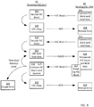
- FIG. 3 shows an example HARQ exchange.
- the first exchange steps 302-308
- the received FEC block was decoded correctly, so no retransmission was needed.
- the second exchange steps 312-322
- a single retransmission was needed for the FEC block to be decoded correctly. Note that since the HARQ operation is operating at the physical layer (PHY layer), the incurred latency is very small.
- FIG. 3 illustrates an exemplary transmission exchange from a sending FSO unit 3A to a receiving FSO unit 2A.
- a first transmission of an FEC block is sent from the sending FSO Unit 3A to the receiving FSO unit 2A.
- the sending FSO unit decodes data on an optical signal and sends the optical transmission to be detected and decoded by the receiving FSO unit.
- the sending FSO unit 3A stores the data of FEC block 1 in memory unit an acknowledgement is received from the receiving FSO unit that a decode was successful. If the receiving FSO unit 2A can decode the FEC block 1 with sufficient confidence then, at step 306, the receiving FSO unit 2A sends an optical signal back to the sending FSO unit acknowledging that the decode was successful.
- the FEC block 1 data is released from memory of the sending FSO unit 3A after the sending FSO unit 3A detects the acknowledgement from the receiving FSO unit 2A.
- a second FEC block is then transmitted at step 308 and the FEC block 2 data saved at the sending FSO unit memory.
- the receiving FSO unit 2A receives the data and attempts to decode the FEC Block 2. If the receiving FSO unit did not receive a full transmission or was not able to decode the FEC block 2 with sufficient confidence, then a bad decode signal is generated, and at step 314 an acknowledgement is sent from the receiving FSO unit 2A to the sending FSO unit 3A indicating the failed transmission.
- the receiving FSO unit 2A saves the received signal in local memory.
- the sending FSO unit 3A resends the same FEC block 2 data to the receiving FSO unit 2A and continues to hold the data in memory.
- the receiving FSO unit combines the FEC blocks presently received and those previously stored. The combined signal is then decoded, If the decode attempt is successful, at step 320 the receiving FSO unit 2A sends and acknowledgement to the sending FSO unit 3A, and the sending FSO unit 3A releases the stored data at step 322. If the decode attempt is unsuccessful, then another NACK is sent and steps 314-318 are repeated until a successful decode is obtained, the maximum number of retries has been reached, a time-out counter has been reached, or any combination thereof. If the counter or timer limit is reached, then an error message or signal may generate, such as at step 324.
- the system, algorithm, and method may also include a time out or retransmission limit such that the data transmission is not stalled at sending the FEC block.
- the receiving FSO unit 2A and/or sending FSO unit 3A may include a counter to track the number of attempts or a relapse time for retransmitting data.
- the receiving and/or sending FSO unit may verify that the retransmission limit has not been reached. If not then a retransmission may be attempted.
- the system may delay retransmission for a given amount of time in an attempt to avoid a temporally local interference, or may use another method to attempt retransmission, such as, for example, increasing power on the transmitted signal. If retransmission is not successful after a predetermined number of attempts, such as, for example, three or five attempts, then the system may generate an error and transmission is temporarily or permanently terminated.
- the system, algorithm, and method may also include an automatic retransmission.
- the sending unit may include an acknowledgement timer that tracks a given time to receive a confirmation, such as the ACK or NACK described herein.
- the acknowledgement timer may track the time from when a FEC block is sent to an expected receipt time.
- the timer limit may be set to just greater than the time to expect the acknowledgement, such as, for example, the transmission speed over the distal between the nodes summed for the round trip signals between the two nodes. If an acknowledgement is not received within the acknowledgement time limit, then the sending unit may retransmit the FEC block according to embodiments described herein.
- the receiving node can disregard the transmission. If the receiving node had not previously decoded the FEC block, such that a NACK was sent, but not received at the sending node, then the receiving node can decode the retransmitted FEC block according to embodiments described herein.
- the FEC block may include header information identifying the FEC block, such that the receiving node can determine if an FEC block is a previously decoded block or not.
- the system may also include dynamic sending parameters, such as power, FEC block size, etc.
- an FEC block may be subdivided such that if a stall is encountered, the FEC block may be segmented and sent in smaller sizes that may be more successful than the larger transmission block.
- the delay may also be dynamic such that if the system determines a series of failed transmissions, the system may wait a predetermined amount of time before attempting another retransmission.
- the system may track history transmission data, or use other data, such as time of day, temperature, etc. to determine whether retransmission at a later time may be more successful. For example, the system may track use and determine that a periodic interference occurs but lasts only an order of microseconds or seconds.
- the system may impose a delay before retransmission when a NACK is acknowledged or after a series of NACKs are received.
- the power may also or alternatively be incrementally increased in an attempt to send a better signal on retransmission.
- the system may observe the retransmit rate over a given duration, and adjust the transmit power statically, semi-statically, or dynamically to achieve the target retransmit rate. For example, the system may look at the retransmission rate for a given period preceding a given FEC block transmission and set a transmission power level to achieve a given retransmission rate. Therefore, the power may be maintained, increased, or decreased depending on the retransmission rate of a preceding duration of transmissions.
- the power level may also be set by a user and the retransmission rate recorded such that a user may adjust the power level based on this recorded information.
- the system may automatically review and adjust the transmission power at certain intervals based on the retransmission rate of a preceding interval.
- HARQ retransmissions are very rapid with all ACK/NACK signaling performed at the PHY layer.
- the overall impact to the system latency is small-typically on the order of a few milliseconds.
- the optimal FEC block size and retransmission rate is dependent upon the fade statistics of the channel.
- the FEC block size is ideally long to exploit interleaving within the FEC block.
- the FEC block should not be significantly longer than the expected mean fade duration.
- longer FEC blocks result in higher FEC coding gains.
- the longer the FEC block size that can be used the better.
- the current two most popular FEC types are block turbo-codes and low density parity check (LDPC) codes. Both are block codes that rely on iterative decoding to achieve near Shannon capacity performance. However, for larger block sizes (> 1000 bits), LDPC codes can be implemented with significantly reduced complexity. In addition, the LDPC decoding algorithm lends itself to a parallel implementation, allowing for soft-decoding operation with multi-gigabit per second data rates.
- a variety of FEC block sizes are used depending on the channel conditions.
- block sizes can be changed on the fly. Shorter block sizes (1-2 kbit) can be used for rapidly fluctuating channels, while longer block sizes (4-16 kbit) can be used for less variable channels. The channel variations can be measured by monitoring the received optical signal strength and determining the time variability of the channel.
- Exemplary embodiments described herein uses soft-information and an analog-to-digital convertor based receiver that samples the incoming data and generates Log-Likelihood Ratios (LLRs) that indicate the likeliness that the received data bit was a '1' or a '0'.
- LLRs Log-Likelihood Ratios
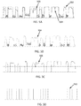
- FIG. 5A illustrates an exemplary data signal as intended to be transmitted 502 and that as received 504 at an FSO detector and that as sampled and digitized 506.
- the actual signal includes noise from other optical sources and interference from the environment, such as atmospheric composition and temperature variations. Accordingly, the received signal is not as easy to detect and decode with confidence.
- the signals are illustrated overlapping for comparison in FIG. 5A and then separated in FIGS. 5B-5D .
- the system may compare the digitized signal at one or more sample locations along the time interval for a bit and compare to a threshold amount to determine a confidence level that the transmitted signal is an assigned symbol. For example, a 1 is assigned for signals above a threshold for a period of time and a zero is assigned for signals below the same or second threshold for a period of time. As shown in FIG. 5C two separate thresholds may be used to determine whether a signal is a 1 or a 0. If the signal falls between the two thresholds, then a sufficient confidence is not provided to assign a symbol. In addition or alternatively thereto, a confidence may be assigned based on the sampling rate and data rate.
- a ADC is used with a sampler such that a sample is taken once per duration associated with a bit length.
- a five bit ADC is used such that a signal is divided into 0-31 levels. If a signal comes in at 0, then there is a strong confidence the associated symbol is 0. If the signal comes in at 31, then there is strong confidence that the associated symbol is 1. However, if the signal comes in at 15, then the symbol is likely a 0, but the confidence is very low.
- the FEC algorithm may fix the bits with the least confidence first.
- the LLR is used by comparing the ratio of the likelihood of a 0 to the likelihood of a 1 and then taking the log.
- a positive number indicates a 0 and a negative number indicates a 1 and the higher the number, the more confident the determination.
- Exemplary embodiments may use 4-12 bit ADC, such that the granularity of the confidence may be controlled between 16 to 4096 levels.
- the original analog signal or the converted digital signal may be added together to make the retransmission total signal that is then compared to the same or different threshold values.
- the LLR values are stored and added together to create a new retransmission total signal.
- the FEC header includes a FEC block ID for the FEC block being transmitted and ACK/NACK bits for previously received FEC blocks.
- the headers are encoded using a stronger FEC code and with repetition to allow for correct decoding of header information even when FEC blocks cannot be decoded.
- a state machine with timers may be used to take into account lost header information.
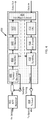
- FIG. 4 illustrates an exemplary Field Programmable Gate Array (FPGA) 400 interfacing with other system components to achieve the functions described herein.
- the FPGA 400 interfaces with the receiver 402 and transmitter 404 to receive and send data across optical signals.
- the FPGA 400 may also receive and send data in the form of electrical signals, such as data bits, that are decoded through the FPGA to/from the optical receiver/transmitter.
- the FPGA 400 includes a number of exemplary components for accomplishing the data coding and HARQ methods described herein.
- the FPGA 400 receives an optical signal that it detected by receiver, such as APD receiver 402.
- the receiver 402 sends electrical signals to the FPGA 400 that correspond to the received optical signals.
- the FPGA therefore includes a symbol recovery 406 that filters, amplifies, digitizes, or otherwise prepares the electronic signal for manipulation.
- the Rx HARQ 408, FEC Decode 410, CRC 412, and Ack/Nack Control 414 work in conjunction to determine whether a new block is being sent or whether a retransmission is sent, determine if a time out or retransmission limit has been reached, add the received signals of retransmitted blocks, decode the FEC block, confirm whether a decode was successful or not, and determine what acknowledgement should be returned.
- the system includes an analog to digital converter to take the analog signal from the receiver and convert to a digital signal.
- the system also includes a sampler to set the sample rate of conversion.
- the FPGA 400 sends an optical signal that is transmitted by Tx laser 404.
- the Ack.Nack Control 414, CRC 416, FEC encoder 418, and Tx HARQ 420 work in conjunction to send a proper acknowledgement, append an appropriate header, encode the desired data into the FEC block, and determine whether a time out has been reached or retransmission limit, and send an appropriate error or data transmission.
- the transmitter state machine can operate independently for each FEC block ID and may include: a timer that when expired, retransmits a FEC block assuming a ACK/NACK was not received; and a counter to limit the maximum number of times a FEC block is retransmitted.
- Each FEC block and header has a calculated Cyclic Redundancy Check (CRC) that is used to indicate if the data has been decoded correctly. If an FEC block is decoded correctly, the bit values are calculated from the LLR data, the bit values then are tagged for output. An output reordering state machine is used to output decoded data in proper sequence.
- CRC Cyclic Redundancy Check
- a timer is used for each FEC block that had not been decoded successfully to determine the maximum amount of time the block is held without being output. If the timer expires, the FEC block is decoded with errors and output.
- HARQ operation can use memory at both the transmitter and receiver.
- bit values of encoded FEC blocks are stored and retransmitted as needed.
- calculated LLR for received FEC blocks are stored.
- the new LLR values are added to the stored LLR values and the updated LLR values are stored if the FEC block is not decoded correctly.
- a memory manager at both the transmitter and receiver can be used to manage FEC block memory to efficiently utilize memory and maximize the number of FEC blocks that can be stored with a given memory size.
- the FSO unit may include a system processor, memory, and a plurality of software routines stored on the memory and executed by the processor to perform the algorithms and methods described herein.
- the processor and memory may be within the PAT controller for example.
- the FSO unit may also include input and/or output circuitry to enable a user to interface with the FSO unit.
Landscapes
- Engineering & Computer Science (AREA)
- Computer Networks & Wireless Communication (AREA)
- Signal Processing (AREA)
- Physics & Mathematics (AREA)
- Probability & Statistics with Applications (AREA)
- Theoretical Computer Science (AREA)
- Electromagnetism (AREA)
- Quality & Reliability (AREA)
- Optical Communication System (AREA)
- Detection And Prevention Of Errors In Transmission (AREA)
Claims (13)
- Ein Verfahren für die Kommunikation über ein optisches Richtfunk (FSO)-System, umfassend:Senden (302, 312) eines ersten optischen Signals, einschließlich Header, Datenblock und zyklischerRedundanzprüfung von einem sendenden FSO-Knoten (3A) und Speichern von Daten, die dem ersten optischen Signal in einem ersten Speicher des sendenden FSO-Knotens entsprechen;Entschlüsselung (304, 310) des ersten optischen Signals durch einen empfangenden FSO-Knoten (2A), um eine mögliche Symbolzuteilung für das erste optische Signal zu bestimmen;Bestimmen eines ersten Konfidenzniveaus der möglichen Symbolzuteilung für das entschlüsselte optische Signal;Senden (314) einer Retransmissionsanfrage, in einem zweiten optischen Signal, durch den empfangenden FSO-Knoten, wenn das erste Konfidenzniveau unter einem Schwellenwert liegt, wobei das zweite optische Signal mit einem Vorwärtsfehlerkorrektur (FEC)-Code gesendet und der Header mit einem höheren FEC-Codegewinn als in einem Datenblock des zweiten optischen Signals übertragen wird;Warten auf ein verzögertes Zeitintervall, durch den sendenden FSO-Knoten, vor dem Senden eines dritten optischenSignals als Reaktion auf die Retransmissionsanfrage, wobei das verzögerte Zeitintervallauf Kanalbedingungen basiert; Senden (316) des dritten optischen Signals, das den in dem ersten Speicher abgelegten Daten entspricht,durch den sendenden FSO-Knoten; Entschlüsseln (318) des dritten optischen Signals durch den empfangenden FSO-Knoten, um diemögliche Symbolzuteilung für das dritte optische Signal zu bestimmen;Bestimmen eines zweiten Konfidenzniveaus der möglichen Symbolzuteilung für das entschlüsselte dritte optische Signal; undSenden (320) einer Übertragungsbestätigung durch den empfangenden FSO-Knoten, wenn das zweiteKonfidenzniveau über dem Schwellenwert liegt, die Übertragungsbestätigung bestätigt die mögliche Symbolzuteilung.
- Verfahren nach Anspruch 1, ferner umfassend:Umsetzen des ersten optischen Signals durch einen empfangenden FSO-Knoten in ein erstes analoges elektrisches Signal;Abtasten des ersten analogen elektrischen Signals mit einem Analog-DigitalUmsetzer an demempfangenden FSO-Knoten, um ein erstes abgetastetes digitales Signal zu schaffen; Umsetzen des dritten optischen Signals durch den empfangenden FSO-Knoten in ein zweites analoges elektrisches Signal;Abtasten des zweiten analogen elektrischen Signals mit einem Analog-DigitalUmsetzer an demempfangenden FSO-Knoten, um ein zweites abgetastetes digitales Signal zu schaffen; Digitalisieren des ersten abgetasteten digitalen Signals durch Zuteilung eines Mehrbitwerts für jede Abtastung,basierend auf Schwellenwerten, um ein erstes digitalisiertes abgetastetes elektrisches Signal zu schaffen; Digitalisieren des zweiten abgetasteten digitalen Signals durch Zuteilung eines Mehrbitwerts für jede Abtastung,basierend auf Schwellenwerten, um ein zweites digitalisiertes abgetastetes elektrisches Signal zu schaffen;
undHinzufügen des zweiten digitalisierten abgetasteten elektrischen Signals zu dem ersten digitalisierten abgetastetenelektrischen Signal durch den empfangenden FSO-Knoten, um ein kombiniertes elektrisches Signal zu definieren. - Das Verfahren nach Anspruch 2, wobei das Entschlüsseln des dritten optischen Signals zum Bestimmen der möglichen Symbolzuteilung für das dritte optische Signal ferner Folgendes umfasst:Umsetzen des ersten digitalisierten abgetasteten elektrischen Signals in ein erstes skaliertes digitales Signalunter Verwendung eines Log-Likelihood-Quotienten; Speichern des ersten skalierten digitalen Signals in einem ersten Speicher der empfangenden FSO-Einheit; Umsetzen des zweiten digitalisierten abgetasteten digitalen Signals in ein zweites skaliertes digitales Signal unter Verwendung eines Log-Likelihood-Quotienten; undHinzufügen des zweiten skalierten digitalen Signals zu dem ersten skalierten digitalen Signal, um das entschlüsselte dritte optische Signal zu definieren.
- Das Verfahren nach Anspruch 3, wobei das Senden eines ersten optischen Signals mit einer ersten Sendeleistung durchgeführt wird, die Sendeleistung ist so ausgewählt, dass sie eine 10-20 Prozent Retransmissionsrate erreicht.
- Das Verfahren nach einem der vorhergehenden Ansprüche, wobei die Kanalbedingungen Kanal-Fading-Statistiken umfassen.
- Das Verfahren nach einem der vorhergehenden Ansprüche, wobei das zweite optische Signal bei erhöhter Sendeleistung als das erste optische Signal gesendet wird.
- Das Verfahren nach einem der vorhergehenden Ansprüche, wobei das zweite optische Signal zu einem verzögerten Zeitpunkt gemäß eines vorbestimmten Intervalls, basierend auf historischen Kanalbedingungen, gesendet wird.
- Das Verfahren nach einem der vorhergehenden Ansprüche, wobei die Kanalbedingungen durch Überwachen einer empfangenen optischen Signalstärke und Bestimmen einer zeitlichen Variabilität des Kanals gemessen werden.
- Das Verfahren nach einem der vorhergehenden Ansprüche, ferner umfassend:Empfangen des dritten optischen Signals durch den empfangenden FSO-Knoten; undBestimmen, durch den empfangenden FSO-Knoten, aus Informationen im Header des dritten optischen Signals, ob das dritte optische Signal eine Retransmission des ersten optischen Signals ist.
- Das Verfahren nach einem der vorhergehenden Ansprüche, wobei der sendende FSO-Knoten das dritte optische Signal sendet, wenn der sendende FSO-Knoten keine Bestätigungsanfrage oder eine Retransmissionsanfrage von dem empfangenden FSO-Knoten nach einer Schwellenzeit empfängt.
- Das Verfahren nach einem der vorhergehenden Ansprüche, wobei das Senden der FSO-Knoten das dritte optische Signal in Blöcke teilt, die Blockgröße hängt von den Kanalbedingungen ab.
- Das Verfahren nach einem der vorhergehenden Ansprüche, wobei die Retransmissionsanfrage in einer PHY-Schicht der empfangenden FSO-Einheit verarbeitet wird.
- Ein optisches Richtfunk (FSO)-Kommunikationssystem, das einen empfangenden FSO-Knoten und einen sendenden FSO-Knoten mit einer Vorrichtung umfasst, das angepasst ist, um die Verfahrensschritte jedes der vorhergehenden Ansprüche auszuführen.
Applications Claiming Priority (2)
| Application Number | Priority Date | Filing Date | Title |
|---|---|---|---|
| US201461932687P | 2014-01-28 | 2014-01-28 | |
| PCT/US2015/013381 WO2015116738A1 (en) | 2014-01-28 | 2015-01-28 | Data retransmission for atmospheric free space optical communication system |
Publications (3)
| Publication Number | Publication Date |
|---|---|
| EP3100379A1 EP3100379A1 (de) | 2016-12-07 |
| EP3100379A4 EP3100379A4 (de) | 2017-09-20 |
| EP3100379B1 true EP3100379B1 (de) | 2019-05-15 |
Family
ID=53680100
Family Applications (1)
| Application Number | Title | Priority Date | Filing Date |
|---|---|---|---|
| EP15742838.4A Active EP3100379B1 (de) | 2014-01-28 | 2015-01-28 | Datenwiederübertragung für atmosphärisches optisches freiraum-kommunikationssystem |
Country Status (5)
| Country | Link |
|---|---|
| US (1) | US10075233B2 (de) |
| EP (1) | EP3100379B1 (de) |
| AU (1) | AU2015211019B2 (de) |
| MX (1) | MX362782B (de) |
| WO (1) | WO2015116738A1 (de) |
Families Citing this family (20)
| Publication number | Priority date | Publication date | Assignee | Title |
|---|---|---|---|---|
| US9438337B2 (en) * | 2014-05-31 | 2016-09-06 | Cisco Technology, Inc. | Control system for multi-beam free space optical endpoint |
| WO2016022579A2 (en) | 2014-08-05 | 2016-02-11 | Massachusetts Institute Of Technology | Design of a free-space optical communication module for small satellites |
| US9998221B2 (en) * | 2015-01-09 | 2018-06-12 | Massachusetts Institute Of Technology | Link architecture and spacecraft terminal for high rate direct to earth optical communications |
| US10128949B2 (en) | 2015-02-27 | 2018-11-13 | Massachusetts Institute Of Technology | Methods, systems, and apparatus for global multiple-access optical communications |
| US9729231B2 (en) * | 2015-03-20 | 2017-08-08 | Oe Solutions America, Inc. | Enhanced transmission and reception of remote digital diagnostic information of optical transceivers |
| GB2530368B (en) * | 2015-06-03 | 2016-08-10 | Bridgeworks Ltd | Transmitting data |
| WO2017035095A1 (en) | 2015-08-21 | 2017-03-02 | SA Photonics, Inc. | Free space optical (fso) system |
| AU2016311179B2 (en) | 2015-08-21 | 2020-03-12 | Caci Photonics, Llc | Free space optical (FSO) system |
| US9973274B1 (en) | 2015-10-07 | 2018-05-15 | SA Photonics, Inc. | Fast tracking free space optical module |
| US10270541B2 (en) * | 2016-04-27 | 2019-04-23 | Magseis Ff Llc | Optical link management |
| US10359570B1 (en) * | 2016-12-22 | 2019-07-23 | X Development Llc | Free-space optical communications beacon source architecture |
| JP6620084B2 (ja) * | 2016-12-27 | 2019-12-11 | 株式会社日立製作所 | 自動点検システムおよび自動点検方法 |
| US10291365B2 (en) * | 2016-12-29 | 2019-05-14 | X Development Llc | Efficient automatic repeat request for free space optical communication |
| AU2019226091A1 (en) * | 2018-02-22 | 2020-09-24 | EOS Defense Systems USA, Inc. | Hybrid wireless link employing free-space optical communication, radio frequency communication, and intelligent frame and packet switching |
| CN109617612A (zh) * | 2018-12-25 | 2019-04-12 | 杭州耀芯科技有限公司 | 自由空间中光信号对准传输装置、系统及方法 |
| US10686521B1 (en) * | 2019-01-23 | 2020-06-16 | X Development Llc | Beam divergence adjustment of a communication beam based on state disturbance estimations |
| DE102020208664A1 (de) * | 2020-07-10 | 2022-01-13 | Robert Bosch Gesellschaft mit beschränkter Haftung | Verfahren und Vorrichtung zum Übertragen von Daten |
| US11909439B2 (en) | 2021-04-23 | 2024-02-20 | SA Photonics, Inc. | Wavefront sensor with inner detector and outer detector |
| US11567264B2 (en) | 2021-04-28 | 2023-01-31 | Com Dev Ltd. | Wavelength separated fine steering assembly |
| US20240039638A1 (en) * | 2022-08-01 | 2024-02-01 | California Institute Of Technology | Complex-wavefront photonic transceiver processor |
Citations (1)
| Publication number | Priority date | Publication date | Assignee | Title |
|---|---|---|---|---|
| US20030206524A1 (en) * | 2002-05-06 | 2003-11-06 | Bibhu Mohanty | Method and apparatus for augmenting physical layer ARQ in a wireless data communication system |
Family Cites Families (34)
| Publication number | Priority date | Publication date | Assignee | Title |
|---|---|---|---|---|
| US5477550A (en) * | 1993-03-08 | 1995-12-19 | Crisler; Kenneth J. | Method for communicating data using a modified SR-ARQ protocol |
| US6683850B1 (en) * | 1997-08-29 | 2004-01-27 | Intel Corporation | Method and apparatus for controlling the flow of data between servers |
| US6141128A (en) * | 1997-12-15 | 2000-10-31 | Astroterra Corporation | Buffered laser communication link |
| US6240094B1 (en) * | 1997-12-22 | 2001-05-29 | Bell Atlantic Network Services, Inc. | Statistical time division multiplexer for a wireless asymmetric local loop communication system |
| US6496520B1 (en) * | 2000-01-21 | 2002-12-17 | Broadcloud Communications, Inc. | Wireless network system and method |
| US7564866B2 (en) * | 2000-07-21 | 2009-07-21 | Broadcom Corporation | Methods and systems for digitally processing optical data signals |
| US6915080B2 (en) * | 2000-09-20 | 2005-07-05 | Mark David Heminger | Method and apparatus for aligning optical wireless links |
| US6678251B2 (en) * | 2001-02-13 | 2004-01-13 | Terabeam Corporation | Link quality agent |
| US20020181055A1 (en) * | 2001-04-20 | 2002-12-05 | Grant Christiansen | System and method for embedding control information within an optical wireless link |
| US6909758B2 (en) | 2001-04-27 | 2005-06-21 | Telefonaktiebolaget Lm Ericsson (Publ) | Systems and methods for decoding data blocks |
| US7263130B1 (en) * | 2001-05-25 | 2007-08-28 | 3Com Corporation | Method and apparatus for evaluating error control parameters of self-similar constellations |
| US7292601B2 (en) * | 2001-06-19 | 2007-11-06 | At&T Corp. | Error-rate management in wireless systems |
| ATE309652T1 (de) * | 2001-11-16 | 2005-11-15 | Matsushita Electric Industrial Co Ltd | Arq wiederübertragungsverfahren mit inkrementaler redundanz unter verwendung von bit umordnungsarten |
| WO2003092213A1 (en) * | 2002-04-24 | 2003-11-06 | Samsung Electronics Co., Ltd. | Apparatus and method for supporting automatic repeat request in a high-speed wireless packet data communication system |
| JP4409446B2 (ja) * | 2003-04-23 | 2010-02-03 | 三菱電機株式会社 | 光受信装置および光伝送システム |
| US7277644B2 (en) * | 2003-06-13 | 2007-10-02 | The Regents Of The University Of California | Fade-resistant forward error correction method for free-space optical communications systems |
| US7280769B2 (en) * | 2003-07-28 | 2007-10-09 | Emerson Electric Co. | Method and apparatus for operating an optical receiver for low intensity optical communication in a high speed mode |
| JP2006054853A (ja) * | 2004-07-14 | 2006-02-23 | Iwatsu Electric Co Ltd | 無線lanにおけるパケット伝送方法及び装置 |
| JP2008547344A (ja) * | 2005-06-27 | 2008-12-25 | コーニンクレッカ フィリップス エレクトロニクス エヌ ヴィ | ワイヤレス通信システムにおけるh−arq用の装置及び方法 |
| AU2008298602A1 (en) * | 2007-09-12 | 2009-03-19 | Digital Fountain, Inc. | Generating and communicating source identification information to enable reliable communications |
| US8351464B2 (en) * | 2007-10-02 | 2013-01-08 | Infineon Technologies Ag | Retransmission in data communication systems |
| US8437406B2 (en) * | 2007-11-12 | 2013-05-07 | Broadcom Corporation | Method and system for digital video broadcast for cable (DVB-C2) |
| US20090213953A1 (en) * | 2008-02-25 | 2009-08-27 | Legend Silicon Corp. | Bit Log Likelihood Ratio (LLR) Computation of a 32-QAM System |
| US8527848B2 (en) * | 2008-06-16 | 2013-09-03 | Lg Electronics Inc. | Cooperative symbol level network coding in multi-channel wireless networks |
| US8363613B2 (en) * | 2010-05-13 | 2013-01-29 | Juniper Networks, Inc. | Increasing throughput by adaptively changing PDU size in wireless networks under low SNR conditions |
| US9445400B2 (en) * | 2010-07-02 | 2016-09-13 | Samsung Electronics Co., Ltd. | Methods and devices for performing an automatic repeat request reset in a wireless communication environment |
| US8595605B2 (en) | 2010-08-20 | 2013-11-26 | Qualcomm Incorporated | Systems and methods for memory management |
| US8948612B2 (en) * | 2010-12-03 | 2015-02-03 | Tyco Electronics Subsea Communications Llc | System and method for generating soft decision reliability information from hard decisions in an optical signal receiver |
| US8539297B1 (en) * | 2011-02-01 | 2013-09-17 | Sprint Communications Company L.P. | Determining whether a wireless access node should retransmit data packets based on the condition of a reverse wireless link |
| US8942562B2 (en) * | 2011-05-31 | 2015-01-27 | A Optix Technologies, Inc. | Integrated commercial communications network using radio frequency and free space optical data communication |
| EP2615749B1 (de) * | 2011-12-20 | 2017-12-06 | Thales Alenia Space Schweiz AG | Verfahren zur optischen datenübertragung aus der erdbeobachtung auf die erde und entsprechendens kommunikationssystem |
| WO2013172756A1 (en) * | 2012-05-14 | 2013-11-21 | Telefonaktiebolaget L M Ericsson (Publ) | Apparatuses and methods for managing pending harq retransmissions |
| US9954643B2 (en) | 2012-06-22 | 2018-04-24 | Samsung Electronics Co., Ltd. | Communication system with repeat-response combining mechanism and method of operation thereof |
| US9094163B2 (en) * | 2012-08-28 | 2015-07-28 | Aoptix Technologies, Inc. | Assessment and correction of transmitted data |
-
2015
- 2015-01-28 EP EP15742838.4A patent/EP3100379B1/de active Active
- 2015-01-28 US US14/608,166 patent/US10075233B2/en active Active
- 2015-01-28 MX MX2016009789A patent/MX362782B/es active IP Right Grant
- 2015-01-28 AU AU2015211019A patent/AU2015211019B2/en active Active
- 2015-01-28 WO PCT/US2015/013381 patent/WO2015116738A1/en not_active Ceased
Patent Citations (1)
| Publication number | Priority date | Publication date | Assignee | Title |
|---|---|---|---|---|
| US20030206524A1 (en) * | 2002-05-06 | 2003-11-06 | Bibhu Mohanty | Method and apparatus for augmenting physical layer ARQ in a wireless data communication system |
Also Published As
| Publication number | Publication date |
|---|---|
| MX2016009789A (es) | 2017-02-28 |
| US20150215041A1 (en) | 2015-07-30 |
| WO2015116738A1 (en) | 2015-08-06 |
| EP3100379A4 (de) | 2017-09-20 |
| AU2015211019A1 (en) | 2016-08-18 |
| MX362782B (es) | 2019-02-08 |
| EP3100379A1 (de) | 2016-12-07 |
| AU2015211019B2 (en) | 2018-11-01 |
| US10075233B2 (en) | 2018-09-11 |
Similar Documents
| Publication | Publication Date | Title |
|---|---|---|
| EP3100379B1 (de) | Datenwiederübertragung für atmosphärisches optisches freiraum-kommunikationssystem | |
| CA2197131C (en) | Adaptive hybrid arq coding schemes for slow fading channels in mobile radio systems | |
| US10237023B2 (en) | Hybrid automatic repeat request method and apparatus in relay wireless communication system using compressed-and-forward scheme | |
| US9094163B2 (en) | Assessment and correction of transmitted data | |
| WO2003098810A1 (en) | Reliability-based hybrid arq scheme | |
| KR20020003526A (ko) | 복합 재전송방식을 사용하는 이동 통신시스템의 데이터재전송 장치 및 방법 | |
| JP2003008553A (ja) | 送信機、受信機、送受信機および通信システム | |
| Badia et al. | Markov analysis of selective repeat type II hybrid ARQ using block codes | |
| JP5651191B2 (ja) | 物理層のデータグラムの再送要求方法及びその装置 | |
| JP6126698B2 (ja) | 受信機の停止イベント後の修正されたharq手順のための方法および装置 | |
| CA2457883A1 (en) | Implementing a physical layer automatic repeat request for a subscriber unit | |
| KR20070053504A (ko) | 통신 시스템에서 데이터 수신 방법 및 장치 | |
| US11936480B2 (en) | Apparatus and methods for HARQ in a wireless network | |
| CN107248904B (zh) | 一种基于联合编码的ldpc码差错控制方法 | |
| WO2017176147A1 (en) | Device and method for adjusting transmission size in case of decoding failures | |
| WO2010041295A1 (ja) | 無線中継装置および中継局における再送方法 | |
| EP3912289B1 (de) | Verfahren zur übertragung eines datenpakets, computerprogramm und sende-empfangseinrichtung | |
| KR20100090413A (ko) | 무선 통신 시스템에서 하이브리드 자동 재전송을 위한 llr 결합 방법 및 이를 위한 장치 | |
| US8249074B2 (en) | Automatic repeat request with adaptive latency | |
| Deghel et al. | Joint optimization of link adaptation and harq retransmissions for urllc services | |
| CN117692103A (zh) | 一种基于比特的数据重传方法及相关装置 | |
| KR20040084212A (ko) | 궤환채널의 상태를 이용한 적응형 Hybrid ARQ 무선 통신 시스템 | |
| US8151168B2 (en) | Method, apparatus and system for error detection and selective retransmission | |
| Cao et al. | Impact of imperfect channel state information on ARQ schemes over Rayleigh fading channels | |
| CN115996084B (zh) | 微波激光融合系统、通信链路的切换方法、设备及介质 |
Legal Events
| Date | Code | Title | Description |
|---|---|---|---|
| PUAI | Public reference made under article 153(3) epc to a published international application that has entered the european phase |
Free format text: ORIGINAL CODE: 0009012 |
|
| STAA | Information on the status of an ep patent application or granted ep patent |
Free format text: STATUS: REQUEST FOR EXAMINATION WAS MADE |
|
| 17P | Request for examination filed |
Effective date: 20160728 |
|
| AK | Designated contracting states |
Kind code of ref document: A1 Designated state(s): AL AT BE BG CH CY CZ DE DK EE ES FI FR GB GR HR HU IE IS IT LI LT LU LV MC MK MT NL NO PL PT RO RS SE SI SK SM TR |
|
| AX | Request for extension of the european patent |
Extension state: BA ME |
|
| DAX | Request for extension of the european patent (deleted) | ||
| REG | Reference to a national code |
Ref country code: DE Ref legal event code: R079 Ref document number: 602015030351 Country of ref document: DE Free format text: PREVIOUS MAIN CLASS: H04B0010110000 Ipc: H04B0010112000 |
|
| A4 | Supplementary search report drawn up and despatched |
Effective date: 20170821 |
|
| RIC1 | Information provided on ipc code assigned before grant |
Ipc: H04L 1/18 20060101ALI20170814BHEP Ipc: H04B 10/112 20130101AFI20170814BHEP Ipc: H03M 13/00 20060101ALI20170814BHEP |
|
| STAA | Information on the status of an ep patent application or granted ep patent |
Free format text: STATUS: EXAMINATION IS IN PROGRESS |
|
| 17Q | First examination report despatched |
Effective date: 20180607 |
|
| GRAP | Despatch of communication of intention to grant a patent |
Free format text: ORIGINAL CODE: EPIDOSNIGR1 |
|
| STAA | Information on the status of an ep patent application or granted ep patent |
Free format text: STATUS: GRANT OF PATENT IS INTENDED |
|
| INTG | Intention to grant announced |
Effective date: 20190118 |
|
| GRAS | Grant fee paid |
Free format text: ORIGINAL CODE: EPIDOSNIGR3 |
|
| GRAA | (expected) grant |
Free format text: ORIGINAL CODE: 0009210 |
|
| STAA | Information on the status of an ep patent application or granted ep patent |
Free format text: STATUS: THE PATENT HAS BEEN GRANTED |
|
| AK | Designated contracting states |
Kind code of ref document: B1 Designated state(s): AL AT BE BG CH CY CZ DE DK EE ES FI FR GB GR HR HU IE IS IT LI LT LU LV MC MK MT NL NO PL PT RO RS SE SI SK SM TR |
|
| REG | Reference to a national code |
Ref country code: CH Ref legal event code: EP |
|
| REG | Reference to a national code |
Ref country code: DE Ref legal event code: R096 Ref document number: 602015030351 Country of ref document: DE |
|
| REG | Reference to a national code |
Ref country code: IE Ref legal event code: FG4D |
|
| REG | Reference to a national code |
Ref country code: NL Ref legal event code: MP Effective date: 20190515 |
|
| REG | Reference to a national code |
Ref country code: LT Ref legal event code: MG4D |
|
| PG25 | Lapsed in a contracting state [announced via postgrant information from national office to epo] |
Ref country code: SE Free format text: LAPSE BECAUSE OF FAILURE TO SUBMIT A TRANSLATION OF THE DESCRIPTION OR TO PAY THE FEE WITHIN THE PRESCRIBED TIME-LIMIT Effective date: 20190515 Ref country code: PT Free format text: LAPSE BECAUSE OF FAILURE TO SUBMIT A TRANSLATION OF THE DESCRIPTION OR TO PAY THE FEE WITHIN THE PRESCRIBED TIME-LIMIT Effective date: 20190915 Ref country code: HR Free format text: LAPSE BECAUSE OF FAILURE TO SUBMIT A TRANSLATION OF THE DESCRIPTION OR TO PAY THE FEE WITHIN THE PRESCRIBED TIME-LIMIT Effective date: 20190515 Ref country code: ES Free format text: LAPSE BECAUSE OF FAILURE TO SUBMIT A TRANSLATION OF THE DESCRIPTION OR TO PAY THE FEE WITHIN THE PRESCRIBED TIME-LIMIT Effective date: 20190515 Ref country code: NL Free format text: LAPSE BECAUSE OF FAILURE TO SUBMIT A TRANSLATION OF THE DESCRIPTION OR TO PAY THE FEE WITHIN THE PRESCRIBED TIME-LIMIT Effective date: 20190515 Ref country code: LT Free format text: LAPSE BECAUSE OF FAILURE TO SUBMIT A TRANSLATION OF THE DESCRIPTION OR TO PAY THE FEE WITHIN THE PRESCRIBED TIME-LIMIT Effective date: 20190515 Ref country code: NO Free format text: LAPSE BECAUSE OF FAILURE TO SUBMIT A TRANSLATION OF THE DESCRIPTION OR TO PAY THE FEE WITHIN THE PRESCRIBED TIME-LIMIT Effective date: 20190815 Ref country code: AL Free format text: LAPSE BECAUSE OF FAILURE TO SUBMIT A TRANSLATION OF THE DESCRIPTION OR TO PAY THE FEE WITHIN THE PRESCRIBED TIME-LIMIT Effective date: 20190515 Ref country code: FI Free format text: LAPSE BECAUSE OF FAILURE TO SUBMIT A TRANSLATION OF THE DESCRIPTION OR TO PAY THE FEE WITHIN THE PRESCRIBED TIME-LIMIT Effective date: 20190515 |
|
| PG25 | Lapsed in a contracting state [announced via postgrant information from national office to epo] |
Ref country code: BG Free format text: LAPSE BECAUSE OF FAILURE TO SUBMIT A TRANSLATION OF THE DESCRIPTION OR TO PAY THE FEE WITHIN THE PRESCRIBED TIME-LIMIT Effective date: 20190815 Ref country code: RS Free format text: LAPSE BECAUSE OF FAILURE TO SUBMIT A TRANSLATION OF THE DESCRIPTION OR TO PAY THE FEE WITHIN THE PRESCRIBED TIME-LIMIT Effective date: 20190515 Ref country code: LV Free format text: LAPSE BECAUSE OF FAILURE TO SUBMIT A TRANSLATION OF THE DESCRIPTION OR TO PAY THE FEE WITHIN THE PRESCRIBED TIME-LIMIT Effective date: 20190515 Ref country code: GR Free format text: LAPSE BECAUSE OF FAILURE TO SUBMIT A TRANSLATION OF THE DESCRIPTION OR TO PAY THE FEE WITHIN THE PRESCRIBED TIME-LIMIT Effective date: 20190816 |
|
| REG | Reference to a national code |
Ref country code: AT Ref legal event code: MK05 Ref document number: 1134653 Country of ref document: AT Kind code of ref document: T Effective date: 20190515 |
|
| PG25 | Lapsed in a contracting state [announced via postgrant information from national office to epo] |
Ref country code: AT Free format text: LAPSE BECAUSE OF FAILURE TO SUBMIT A TRANSLATION OF THE DESCRIPTION OR TO PAY THE FEE WITHIN THE PRESCRIBED TIME-LIMIT Effective date: 20190515 Ref country code: DK Free format text: LAPSE BECAUSE OF FAILURE TO SUBMIT A TRANSLATION OF THE DESCRIPTION OR TO PAY THE FEE WITHIN THE PRESCRIBED TIME-LIMIT Effective date: 20190515 Ref country code: SK Free format text: LAPSE BECAUSE OF FAILURE TO SUBMIT A TRANSLATION OF THE DESCRIPTION OR TO PAY THE FEE WITHIN THE PRESCRIBED TIME-LIMIT Effective date: 20190515 Ref country code: CZ Free format text: LAPSE BECAUSE OF FAILURE TO SUBMIT A TRANSLATION OF THE DESCRIPTION OR TO PAY THE FEE WITHIN THE PRESCRIBED TIME-LIMIT Effective date: 20190515 Ref country code: EE Free format text: LAPSE BECAUSE OF FAILURE TO SUBMIT A TRANSLATION OF THE DESCRIPTION OR TO PAY THE FEE WITHIN THE PRESCRIBED TIME-LIMIT Effective date: 20190515 |
|
| REG | Reference to a national code |
Ref country code: DE Ref legal event code: R097 Ref document number: 602015030351 Country of ref document: DE |
|
| PG25 | Lapsed in a contracting state [announced via postgrant information from national office to epo] |
Ref country code: IT Free format text: LAPSE BECAUSE OF FAILURE TO SUBMIT A TRANSLATION OF THE DESCRIPTION OR TO PAY THE FEE WITHIN THE PRESCRIBED TIME-LIMIT Effective date: 20190515 Ref country code: SM Free format text: LAPSE BECAUSE OF FAILURE TO SUBMIT A TRANSLATION OF THE DESCRIPTION OR TO PAY THE FEE WITHIN THE PRESCRIBED TIME-LIMIT Effective date: 20190515 |
|
| PLBE | No opposition filed within time limit |
Free format text: ORIGINAL CODE: 0009261 |
|
| STAA | Information on the status of an ep patent application or granted ep patent |
Free format text: STATUS: NO OPPOSITION FILED WITHIN TIME LIMIT |
|
| PG25 | Lapsed in a contracting state [announced via postgrant information from national office to epo] |
Ref country code: TR Free format text: LAPSE BECAUSE OF FAILURE TO SUBMIT A TRANSLATION OF THE DESCRIPTION OR TO PAY THE FEE WITHIN THE PRESCRIBED TIME-LIMIT Effective date: 20190515 |
|
| 26N | No opposition filed |
Effective date: 20200218 |
|
| PG25 | Lapsed in a contracting state [announced via postgrant information from national office to epo] |
Ref country code: PL Free format text: LAPSE BECAUSE OF FAILURE TO SUBMIT A TRANSLATION OF THE DESCRIPTION OR TO PAY THE FEE WITHIN THE PRESCRIBED TIME-LIMIT Effective date: 20190515 |
|
| PG25 | Lapsed in a contracting state [announced via postgrant information from national office to epo] |
Ref country code: SI Free format text: LAPSE BECAUSE OF FAILURE TO SUBMIT A TRANSLATION OF THE DESCRIPTION OR TO PAY THE FEE WITHIN THE PRESCRIBED TIME-LIMIT Effective date: 20190515 |
|
| PG25 | Lapsed in a contracting state [announced via postgrant information from national office to epo] |
Ref country code: MC Free format text: LAPSE BECAUSE OF FAILURE TO SUBMIT A TRANSLATION OF THE DESCRIPTION OR TO PAY THE FEE WITHIN THE PRESCRIBED TIME-LIMIT Effective date: 20190515 |
|
| REG | Reference to a national code |
Ref country code: CH Ref legal event code: PL |
|
| REG | Reference to a national code |
Ref country code: BE Ref legal event code: MM Effective date: 20200131 |
|
| PG25 | Lapsed in a contracting state [announced via postgrant information from national office to epo] |
Ref country code: LU Free format text: LAPSE BECAUSE OF NON-PAYMENT OF DUE FEES Effective date: 20200128 |
|
| PG25 | Lapsed in a contracting state [announced via postgrant information from national office to epo] |
Ref country code: BE Free format text: LAPSE BECAUSE OF NON-PAYMENT OF DUE FEES Effective date: 20200131 Ref country code: CH Free format text: LAPSE BECAUSE OF NON-PAYMENT OF DUE FEES Effective date: 20200131 Ref country code: LI Free format text: LAPSE BECAUSE OF NON-PAYMENT OF DUE FEES Effective date: 20200131 |
|
| PG25 | Lapsed in a contracting state [announced via postgrant information from national office to epo] |
Ref country code: IE Free format text: LAPSE BECAUSE OF NON-PAYMENT OF DUE FEES Effective date: 20200128 |
|
| PG25 | Lapsed in a contracting state [announced via postgrant information from national office to epo] |
Ref country code: MT Free format text: LAPSE BECAUSE OF FAILURE TO SUBMIT A TRANSLATION OF THE DESCRIPTION OR TO PAY THE FEE WITHIN THE PRESCRIBED TIME-LIMIT Effective date: 20190515 Ref country code: CY Free format text: LAPSE BECAUSE OF FAILURE TO SUBMIT A TRANSLATION OF THE DESCRIPTION OR TO PAY THE FEE WITHIN THE PRESCRIBED TIME-LIMIT Effective date: 20190515 |
|
| PG25 | Lapsed in a contracting state [announced via postgrant information from national office to epo] |
Ref country code: RO Free format text: LAPSE BECAUSE OF FAILURE TO SUBMIT A TRANSLATION OF THE DESCRIPTION OR TO PAY THE FEE WITHIN THE PRESCRIBED TIME-LIMIT Effective date: 20190515 Ref country code: MK Free format text: LAPSE BECAUSE OF FAILURE TO SUBMIT A TRANSLATION OF THE DESCRIPTION OR TO PAY THE FEE WITHIN THE PRESCRIBED TIME-LIMIT Effective date: 20190515 Ref country code: IS Free format text: LAPSE BECAUSE OF FAILURE TO SUBMIT A TRANSLATION OF THE DESCRIPTION OR TO PAY THE FEE WITHIN THE PRESCRIBED TIME-LIMIT Effective date: 20190915 |
|
| P01 | Opt-out of the competence of the unified patent court (upc) registered |
Effective date: 20230513 |
|
| REG | Reference to a national code |
Ref country code: DE Ref legal event code: R081 Ref document number: 602015030351 Country of ref document: DE Owner name: CACI PHOTONICS, LLC, LOS GATOS, US Free format text: FORMER OWNER: SA PHOTONICS, INC., LOS GATOS, CA, US |
|
| PGFP | Annual fee paid to national office [announced via postgrant information from national office to epo] |
Ref country code: GB Payment date: 20260127 Year of fee payment: 12 |
|
| PGFP | Annual fee paid to national office [announced via postgrant information from national office to epo] |
Ref country code: DE Payment date: 20260128 Year of fee payment: 12 |
|
| PGFP | Annual fee paid to national office [announced via postgrant information from national office to epo] |
Ref country code: FR Payment date: 20260126 Year of fee payment: 12 |