EP3100600B1 - Elektrisches modul mit spanneinrichtung - Google Patents
Elektrisches modul mit spanneinrichtung Download PDFInfo
- Publication number
- EP3100600B1 EP3100600B1 EP14715225.0A EP14715225A EP3100600B1 EP 3100600 B1 EP3100600 B1 EP 3100600B1 EP 14715225 A EP14715225 A EP 14715225A EP 3100600 B1 EP3100600 B1 EP 3100600B1
- Authority
- EP
- European Patent Office
- Prior art keywords
- module
- stack
- component
- hollow body
- component stack
- Prior art date
- Legal status (The legal status is an assumption and is not a legal conclusion. Google has not performed a legal analysis and makes no representation as to the accuracy of the status listed.)
- Active
Links
Images

Classifications
-
- H—ELECTRICITY
- H10—SEMICONDUCTOR DEVICES; ELECTRIC SOLID-STATE DEVICES NOT OTHERWISE PROVIDED FOR
- H10W—GENERIC PACKAGES, INTERCONNECTIONS, CONNECTORS OR OTHER CONSTRUCTIONAL DETAILS OF DEVICES COVERED BY CLASS H10
- H10W42/00—Arrangements for protection of devices
- H10W42/121—Arrangements for protection of devices protecting against mechanical damage
-
- G—PHYSICS
- G12—INSTRUMENT DETAILS
- G12B—CONSTRUCTIONAL DETAILS OF INSTRUMENTS, OR COMPARABLE DETAILS OF OTHER APPARATUS, NOT OTHERWISE PROVIDED FOR
- G12B17/00—Screening
- G12B17/08—Screening from influences producing mechanical damage, e.g. caused by blast, by external objects, by person
-
- H—ELECTRICITY
- H05—ELECTRIC TECHNIQUES NOT OTHERWISE PROVIDED FOR
- H05K—PRINTED CIRCUITS; CASINGS OR CONSTRUCTIONAL DETAILS OF ELECTRIC APPARATUS; MANUFACTURE OF ASSEMBLAGES OF ELECTRICAL COMPONENTS
- H05K7/00—Constructional details common to different types of electric apparatus
- H05K7/20—Modifications to facilitate cooling, ventilating, or heating
- H05K7/2089—Modifications to facilitate cooling, ventilating, or heating for power electronics, e.g. for inverters for controlling motor
- H05K7/209—Heat transfer by conduction from internal heat source to heat radiating structure
-
- H—ELECTRICITY
- H10—SEMICONDUCTOR DEVICES; ELECTRIC SOLID-STATE DEVICES NOT OTHERWISE PROVIDED FOR
- H10W—GENERIC PACKAGES, INTERCONNECTIONS, CONNECTORS OR OTHER CONSTRUCTIONAL DETAILS OF DEVICES COVERED BY CLASS H10
- H10W40/00—Arrangements for thermal protection or thermal control
- H10W40/60—Securing means for detachable heating or cooling arrangements, e.g. clamps
- H10W40/611—Bolts or screws
- H10W40/613—Bolts or screws for stacked arrangements of a plurality of semiconductor devices
-
- H—ELECTRICITY
- H10—SEMICONDUCTOR DEVICES; ELECTRIC SOLID-STATE DEVICES NOT OTHERWISE PROVIDED FOR
- H10W—GENERIC PACKAGES, INTERCONNECTIONS, CONNECTORS OR OTHER CONSTRUCTIONAL DETAILS OF DEVICES COVERED BY CLASS H10
- H10W72/00—Interconnections or connectors in packages
-
- H—ELECTRICITY
- H10—SEMICONDUCTOR DEVICES; ELECTRIC SOLID-STATE DEVICES NOT OTHERWISE PROVIDED FOR
- H10W—GENERIC PACKAGES, INTERCONNECTIONS, CONNECTORS OR OTHER CONSTRUCTIONAL DETAILS OF DEVICES COVERED BY CLASS H10
- H10W76/00—Containers; Fillings or auxiliary members therefor; Seals
- H10W76/01—Manufacture or treatment
- H10W76/05—Providing fillings in containers, e.g. gas filling
-
- H—ELECTRICITY
- H10—SEMICONDUCTOR DEVICES; ELECTRIC SOLID-STATE DEVICES NOT OTHERWISE PROVIDED FOR
- H10W—GENERIC PACKAGES, INTERCONNECTIONS, CONNECTORS OR OTHER CONSTRUCTIONAL DETAILS OF DEVICES COVERED BY CLASS H10
- H10W76/00—Containers; Fillings or auxiliary members therefor; Seals
- H10W76/10—Containers or parts thereof
- H10W76/12—Containers or parts thereof characterised by their shape
- H10W76/13—Containers comprising a conductive base serving as an interconnection
- H10W76/138—Containers comprising a conductive base serving as an interconnection having another interconnection being formed by a cover plate parallel to the conductive base, e.g. sandwich type
-
- H—ELECTRICITY
- H10—SEMICONDUCTOR DEVICES; ELECTRIC SOLID-STATE DEVICES NOT OTHERWISE PROVIDED FOR
- H10W—GENERIC PACKAGES, INTERCONNECTIONS, CONNECTORS OR OTHER CONSTRUCTIONAL DETAILS OF DEVICES COVERED BY CLASS H10
- H10W76/00—Containers; Fillings or auxiliary members therefor; Seals
- H10W76/10—Containers or parts thereof
- H10W76/12—Containers or parts thereof characterised by their shape
- H10W76/15—Containers comprising an insulating or insulated base
-
- H—ELECTRICITY
- H10—SEMICONDUCTOR DEVICES; ELECTRIC SOLID-STATE DEVICES NOT OTHERWISE PROVIDED FOR
- H10W—GENERIC PACKAGES, INTERCONNECTIONS, CONNECTORS OR OTHER CONSTRUCTIONAL DETAILS OF DEVICES COVERED BY CLASS H10
- H10W76/00—Containers; Fillings or auxiliary members therefor; Seals
- H10W76/40—Fillings or auxiliary members in containers, e.g. centering rings
- H10W76/42—Fillings
- H10W76/43—Gaseous fillings
-
- H—ELECTRICITY
- H10—SEMICONDUCTOR DEVICES; ELECTRIC SOLID-STATE DEVICES NOT OTHERWISE PROVIDED FOR
- H10W—GENERIC PACKAGES, INTERCONNECTIONS, CONNECTORS OR OTHER CONSTRUCTIONAL DETAILS OF DEVICES COVERED BY CLASS H10
- H10W90/00—Package configurations
-
- H—ELECTRICITY
- H10—SEMICONDUCTOR DEVICES; ELECTRIC SOLID-STATE DEVICES NOT OTHERWISE PROVIDED FOR
- H10W—GENERIC PACKAGES, INTERCONNECTIONS, CONNECTORS OR OTHER CONSTRUCTIONAL DETAILS OF DEVICES COVERED BY CLASS H10
- H10W42/00—Arrangements for protection of devices
- H10W42/80—Arrangements for protection of devices protecting against overcurrent or overload, e.g. fuses or shunts
-
- H—ELECTRICITY
- H10—SEMICONDUCTOR DEVICES; ELECTRIC SOLID-STATE DEVICES NOT OTHERWISE PROVIDED FOR
- H10W—GENERIC PACKAGES, INTERCONNECTIONS, CONNECTORS OR OTHER CONSTRUCTIONAL DETAILS OF DEVICES COVERED BY CLASS H10
- H10W90/00—Package configurations
- H10W90/20—Configurations of stacked chips
- H10W90/288—Configurations of stacked chips characterised by arrangements for thermal management of the stacked chips
Definitions
- the invention relates to electrical modules with electrical components, in particular component stacks, in which a clamping force is generated for clamping.
- Multilevel converters are included in the conference contribution " An Alternative Modular Multilevel Converter Topology Suitable for a Wide Power Range "(Anton Lesnicar and Rainer Marquardt, 2003 IEEE Bologna Power Tech Conference, June 23th-26th, Bologna, Italy ).
- the support structure comprises an inflatable cushion, which is provided to spatially fix a circuit board within the support structure.
- Another cooling device for cooling electronic components with expandable cooling elements is from the FR 2 977 949 A1 known.
- the invention is therefore based on the object of specifying an electrical module in which a clamping force for clamping the module can be generated with very little effort and very homogeneously over the module surface.
- the electrical module has at least one hollow body which is filled or can be filled with a medium, in particular a fluid, and which exerts a pressure force on at least one component of the module which is dependent on its internal pressure prevailing inside the hollow body.
- a major advantage of the module according to the invention is that a homogeneous compressive force for bracing the module can be generated with very little effort; it is sufficient to fill the hollow body and to increase its internal pressure.
- the pressure generated in this way is at least approximately homogeneous over the entire cross-sectional area of the hollow body.
- the hollow body is formed by a bubble or a balloon, the size of which is dependent on the pressure.
- the hollow body is preferably stretchable and preferably consists of an elastically deformable material (e.g. plastic or rubber); alternatively, the shell of the hollow body can also consist of a material that is not or only slightly stretchable, such as a metal foil.
- the size of the cross-sectional area of the hollow body - seen in cross-section transverse to the longitudinal direction of the module - corresponds to the cross-sectional area of the component.
- the medium can be compressed.
- the medium is preferably a gas, in particular air.
- the hollow body forms a gas pressure spring which, as part of a tensioning device bracing the module, exerts a spring force on the at least one component of the module.
- the module has at least one component stack which contains two or more components.
- the hollow body forms part of a clamping device that compresses the component stack.
- the module has two or more hollow bodies, it is advantageous if the hollow bodies are connected to one another in terms of pressure.
- a pressure connection simplifies the filling of the hollow body; on the other hand, the formation of a cross-module pressure spring tensioning system is achieved by the pressure connection, which clamps the module across the modules in a spring-loaded manner.
- At least one of the hollow bodies according to the invention is arranged outside the component stack and exerts a compressive force on the component stack from the outside.
- the hollow body which is arranged outside the component stack is preferably arranged in a receiving container which forms an abutment and has a container opening in the direction of the component stack through which the hollow body exerts its compressive force on the component stack.
- the module has at least two hollow bodies, namely a first hollow body which is arranged at a first stack end of the component stack and exerts a compressive force on the first stack end from the outside, and a second hollow body which is located at a second stack end of the component stack is arranged and exerts a compressive force on the second end of the stack from the outside.
- the first hollow body arranged outside the component stack is arranged in a first receiving container which forms a first abutment and has a container opening facing the first stack end of the component stack, through which the first hollow body exerts its compressive force on the first stack end of the component stack
- the second hollow body which is arranged outside the component stack is arranged in a second receiving container which forms a second abutment and which has a container opening facing the second stack end of the component stack, through which the second hollow body exerts its compressive force on the second stack end of the component stack.
- At least one of the hollow bodies lies inside the component stack, segmenting the component stack to form stack segments and one of its Internal pressure-dependent pressure force exerts on the stack segments adjacent to it.
- the component stack preferably has semiconductor components, in particular semiconductor switching elements and / or rectifying elements, heat sinks and / or connection electrodes, as components.
- the invention also relates to a method for tensioning an electrical module having at least one component.
- At least one hollow body of a clamping device of the module is filled with a fluid until the hollow body exerts a predetermined minimum compressive force directly or indirectly on the component.
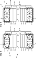
- the Figure 1 shows an electrical module 10 which is equipped with a component stack 20.
- the component stack 20 consists of a plurality of components, of which in the Figure 1 Semiconductor components and heat sinks are identified by the reference numerals 21 and 22.
- the electrical module 10 is equipped with a clamping device 30, which forms a clamping assembly.
- the clamping device 30 has a first expandable hollow body 40 and a second expandable hollow body 50.
- the two expandable hollow bodies 40 and 50 can be formed, for example, by bubbles or expandable balloons.
- the first in the Figure 1 upper hollow body 40 is held in a first receptacle 60 which is mounted in a stationary manner and forms an abutment for the hollow body 40.
- the first receptacle 60 has a container opening 61 through which the hollow body 40 opens into a Figure 1 the upper stack end 20a - hereinafter called the first stack end - of the component stack 20 can exert a compressive force.
- the second hollow body 50 is located in a second receptacle 70, which is also mounted in a stationary manner and forms an abutment for the second hollow body 50. Through a container opening 71 of the receptacle 70, the second hollow body 50 with one in the Figure 1 lower or second stack end 20b of the component stack 20 in connection.
- the two hollow bodies 40 and 50 are coupled in terms of pressure via a pressure line 80 and can be filled with a medium, for example a compressible medium such as air, via a valve 90.
- the two hollow bodies 40 and 50, the pressure line 80 and the valve 90 form an externally gas-tight and - due to the pressure line 80 - pressure-coupled pressure spring tensioning system 100 of the tensioning device 30 or of the electrical module 10.
- the Figure 1 shows the two hollow bodies 40 and 50 at an average gas pressure P1, at which the two hollow bodies 40 and 50 lie on the two stack ends 20a and 20b of the component stack 20, but exert only a small compressive force F1 on the component stack 20.
- the compression spring tensioning system 100 is filled with gas via the valve 90 and the internal pressure in the two hollow bodies 40 and 50 is increased.
- the two hollow bodies 40 and 50 expand, as in FIG Figure 2 is shown. It can be seen that the two hollow bodies 40 and 50 completely fill the assigned receptacles 60 and 70 and the contact pressure against the two stack ends 20a and 20b of the component stack 20 is significantly increased.
- the compressive force on the two stack ends 20a and 20b is in the Figure 2 marked with the reference symbol F2.
- the Figure 3 shows an embodiment of an electrical module 10, the component stack 20 of the component stack of the electrical module 10 according to the Figures 1 and 2 can correspond. Accordingly, the component stack 20 also points in accordance with Figure 3 Semiconductor components 21 and heat sink 22.
- a clamping device 30 is provided in the electrical module 10, which comprises only a single stretchable hollow body 40.
- the hollow body 40 is held in a receiving container 60 forming an abutment, through the container opening 61 of which the hollow body 40 on the in the Figure 3 top stack end 20a of the component stack 20 rests.
- the Figure 3 shows the electrical module 10 at an average gas pressure in the interior of the hollow body 40. It can be seen that the hollow body 40 rests on the first stack end 20a of the component stack 20, but the contact pressure by the hollow body 40 is still low. The contact pressure between the pressure force is in the Figure 3 marked with the reference symbol F1.
- the Figure 4 shows the electrical module 10 after the gas pressure in the interior of the hollow body 40 has been increased, so that the hollow body 40 completely fills the associated receiving container 60 and exerts a significant compressive force F2 on the component stack 20 via the container opening 61. So the following applies: F 2 > > F 1 ,
- the components of the component stack 20 are pressed together, so that the electrical contact resistance between the components of the component stack 20 is minimized.
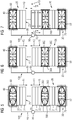
- the Figure 5 shows an embodiment of an electrical module, in which a component stack 20 has a plurality of semiconductor components 21 and a plurality of heat sinks 22.
- a clamping device 30 is provided, which has two outer expandable hollow bodies 40 and 50 and one hollow body 200 inside the component stack 20 or inside.
- the two outer hollow bodies 40 and 50 are held in receptacles 60 and 70, which each form abutments for the clamping device 30.
- the hollow bodies 40 and 50 and the receptacles 60 and 70 can the hollow bodies and receptacles according to the Figures 1 and 2 correspond, so that reference is made to the above statements in this regard.
- the two hollow bodies 40 and 50 and the inner hollow body 200 are connected to one another in terms of pressure via a pressure line 80 and can be filled with gas via a valve 90.
- the three hollow bodies 40, 50 and 200, the pressure line 80 and the valve 90 form an externally gas-tight and - due to the pressure line 80 - pressure-coupled pressure spring tensioning system 100, with which the component stack 20 can be compressed or tensioned.
- the component stack 20 is divided into two stack segments 25 and 26 by the internal hollow body 200.
- the stack segments 25 and 26 can be electrically isolated from one another by the internal hollow body 200.
- Such electrical plates are indicated by way of example in FIG. 5 and marked with reference number 300.
- the plates 300 can not only perform an electrical function for connecting the stack segments 25 and 26, but also form a lateral boundary for the hollow body 200, through which the lateral extension of the hollow body 200 perpendicular to the longitudinal direction of the component stack 20 in the case of a Pressure increase is prevented.
- the Figure 5 shows the compression spring tensioning system 100 or the three hollow bodies 40, 50 and 200 at an average gas pressure P1 at which the component stack 20 is compressed with only a small pressure force F1.
- the Figure 6 shows the electrical module 10 according to FIG Figure 5 after the pressure P2 acting on the component stack 20 has been significantly increased by increasing the pressure P2 inside the three hollow bodies 40, 50 and 200.
- the increased Pressure is in the Figure 6 marked with the reference symbol F2. So the following applies: F 2 > > F 1 and P 2 > > P 1 ,
- the components of the component stack 20 are pressed together, so that the contact resistance between the components is minimized.
- the Figure 7 shows the operation or operation of the three hollow bodies 40, 50 and 200 in the event of failure of one or more of the components of the component stack 20 and an explosion that occurs.
- the pressure wave caused by the explosion which in the Figure 7 is symbolized by a pressure P3 and a pressure force F3, is completely or at least partially absorbed by the hollow bodies 40, 50 and 200, which are connected to one another in terms of pressure.
- the hollow bodies 40, 50 and 200 operate, so to speak, as shock absorbers, by means of which the mechanical forces acting on the remaining, not exploded and still functional components of the component stack 20 are reduced or reduced.
- a mechanical destruction of the other, not exploded components of the component stack 20 can thus be advantageously avoided by the hollow bodies 40, 50 and 200 of the compression spring tensioning system 100 working as gas pressure springs, at the same time the tension bandage remains stiff enough and does not open even during a fault event or not significant.
Landscapes
- Engineering & Computer Science (AREA)
- Microelectronics & Electronic Packaging (AREA)
- Physics & Mathematics (AREA)
- Thermal Sciences (AREA)
- Filling Or Discharging Of Gas Storage Vessels (AREA)
- Inverter Devices (AREA)
- Cooling Or The Like Of Electrical Apparatus (AREA)
- Installation Of Indoor Wiring (AREA)
- Fuel Cell (AREA)
- Cooling Or The Like Of Semiconductors Or Solid State Devices (AREA)
Description
- Die Erfindung bezieht sich auf elektrische Module mit elektrischen Bauelementen, insbesondere Bauelementstapeln, bei denen zum Verspannen eine Spannkraft erzeugt wird.
- Elektrische Module mit Bauelementstapeln sind beispielsweise auf dem Gebiet der Multilevelumrichter bekannt. Multilevelumrichter sind zum Beispiel in dem Konferenzbeitrag "An Innovative Modular Multilevel Converter Topology Suitable for a Wide Power Range" (Anton Lesnicar und Rainer Marquardt, 2003 IEEE Bologna Power Tech Conference, June 23th-26th, Bologna, Italy), beschrieben.
- Aus der
JP H08 264981 A - Die Druckschrift
US 2010/0039770 A1 offenbart eine weitere elektrische Einrichtung, bei der zwischen die Komponenten der Einrichtung ein aufblasbares Kissen eingesetzt ist. Durch eine Volumenerweiterung des Kissens, kann dieses eine Drucckraft auf die anliegenden Komponenten ausüben, die dadurch einen verbesserten Kontakt zu ihnen zugeordneten Kühlmodulen aufweisen. - Im Beitrag "Inflatable Internal Computer Structure", IBM Technical Disclosure Bulletin, vom Januar 1996, ist eine Stützstruktur für Bauteile eines tragbaren Rechners offenbart. Die Stützstruktur umfasst ein aufblasbares Kissen, das dazu vorgesehen ist, eine Leiterplatte innerhalb der Stützstruktur räumlich zu fixieren.
- Eine weitere Kühlvorrichtung zur Kühlung elektronischer Komponenten mit volumenerweiterbaren Kühlelementen ist aus der
FR 2 977 949 A1 - Um bei aufeinandergestapelten Bauelementen bzw. bei Bauelementstapeln die zum mechanischen Verspannen erforderlichen Spannkräfte zu erzeugen, werden heutzutage Gewindesysteme in Kombination mit Tellerfedern oder anderen Federelementen eingesetzt, die eine mechanische Kraft in das mechanische System einleiten. Die Spannkrafteinbringung erfolgt in der Regel jedoch sehr punktuell mit einem oder mehreren Schraubelementen über Druckstücke, so dass sich eine großflächige homogene Verteilung der Spannkraft nicht immer erreichen lässt. Gerade für sehr große Halbleiterelemente ist es mit den bekannten punktuellen Gewindemechaniken sehr schwierig, eine homogene Spannkraftverteilung über die gesamte Halbleiterfläche zu realisieren.
- Der Erfindung liegt demgemäß die Aufgabe zugrunde, ein elektrisches Modul anzugeben, bei dem sich eine Spannkraft zum Verspannen des Moduls mit sehr geringem Aufwand sowie sehr homogen über der Modulfläche erzeugen lässt.
- Diese Aufgabe wird erfindungsgemäß durch ein elektrisches Modul mit den Merkmalen gemäß Patentanspruch 1 gelöst. Vorteilhafte Ausgestaltungen des erfindungsgemäßen Moduls sind in Unteransprüchen angegeben.
- Danach ist erfindungsgemäß vorgesehen, dass das elektrische Modul zumindest einen mit einem Medium, insbesondere einem Fluid, gefüllten oder füllbaren Hohlkörper aufweist, der eine von seinem im Inneren des Hohlkörpers herrschenden Innendruck abhängige Druckkraft auf mindestens ein Bauelement des Moduls ausübt.
- Ein wesentlicher Vorteil des erfindungsgemäßen Moduls besteht darin, dass eine homogene Druckkraft zum Verspannen des Moduls mit sehr geringem Aufwand erzeugt werden kann; es reicht aus, den Hohlkörper zu füllen und dessen Innendruck zu erhöhen. Der dadurch erzeugte Druck ist über die die gesamte Querschnittsfläche des Hohlkörpers zumindest annähernd homogen.
- Besonders kostengünstig ist es, wenn der Hohlkörper durch eine Blase oder einen Ballon gebildet ist, dessen Größe druckabhängig ist. Der Hohlkörper ist vorzugsweise dehnbar und besteht bevorzugt aus einem elastisch deformierbaren Material (z. B. Kunststoff oder Gummi); alternativ kann die Hülle des Hohlkörpers auch aus einem wenig oder gar nicht dehnbaren Material bestehen, wie beispielsweise einer Metallfolie.
- Mit Blick auf eine homogene Druckkraftverteilung im Inneren des Moduls wird es als vorteilhaft angesehen, wenn die Größe der Querschnittsfläche des Hohlkörpers - im Querschnitt quer zur Längsrichtung des Moduls gesehen - der Querschnittsfläche des Bauelements entspricht.
- Um eine Doppelfunktion des Hohlkörpers zu erreichen, nämlich zum einen die Funktion einer Druckkrafterzeugung und zum anderen die Funktion einer Federung, wird es als vorteilhaft angesehen, wenn das Medium komprimierbar ist. Vorzugsweise handelt es sich bei dem Medium um ein Gas, insbesondere um Luft. Mit anderen Worten ist es also vorteilhaft, wenn der Hohlkörper eine Gasdruckfeder bildet, die als Bestandteil einer das Modul verspannenden Spanneinrichtung eine Federkraft auf das mindestens eine Bauelement des Moduls ausübt.
- Das Modul weist erfindungsgemäß mindestens einen Bauelementstapel auf, der zwei oder mehr Bauelemente enthält. Der Hohlkörper bildet dabei einen Bestandteil einer Spanneinrichtung bildet, die den Bauelementstapel zusammendrückt.
- Weist das Modul zwei oder mehr Hohlkörper auf, so ist es vorteilhaft, wenn die Hohlkörper druckmäßig miteinander in Verbindung stehen. Eine druckmäßige Verbindung vereinfacht zum einen das Befüllen der Hohlkörper; zum anderen wird durch die druckmäßige Verbindung die Bildung eines modulübergreifenden Druckfederspannsystems erreicht, das das Modul modulübergreifend federnd verspannt.
- Bezüglich der Anordnung der Hohlkörper ist zumindest einer der Hohlkörper erfindungsgemäß außerhalb des Bauelementstapels angeordnet und übt von außen eine Druckkraft auf den Bauelementstapel aus. Vorzugsweise ist der außerhalb des Bauelementstapels angeordnete Hohlkörper in einem ein Widerlager bildenden Aufnahmebehälter angeordnet, der in Richtung des Bauelementstapels eine Behälteröffnung aufweist, durch die der Hohlkörper seine Druckkraft auf den Bauelementstapel ausübt.
- Als besonders vorteilhaft wird es angesehen, wenn das Modul zumindest zwei Hohlkörper aufweist, nämlich einen ersten Hohlkörper, der an einem ersten Stapelende des Bauelementstapels angeordnet ist und von außen eine Druckkraft auf das erste Stapelende ausübt, und einen zweiten Hohlkörper, der an einem zweiten Stapelende des Bauelementstapels angeordnet ist und von außen eine Druckkraft auf das zweite Stapelende ausübt.
- Bei der letztgenannten Variante ist es besonders vorteilhaft, wenn der erste außerhalb des Bauelementstapels angeordnete Hohlkörper in einem ein erstes Widerlager bildenden ersten Aufnahmebehälter angeordnet ist, der eine dem ersten Stapelende des Bauelementstapels zugewandte Behälteröffnung aufweist, durch die der erste Hohlkörper seine Druckkraft auf das erste Stapelende des Bauelementstapels ausübt, und der zweite außerhalb des Bauelementstapels angeordnete Hohlkörper in einem ein zweites Widerlager bildenden zweiten Aufnahmebehälter angeordnet ist, der eine dem zweiten Stapelende des Bauelementstapels zugewandte Behälteröffnung aufweist, durch die der zweite Hohlkörper seine Druckkraft auf das zweite Stapelende des Bauelementstapels ausübt.
- Mit Blick auf eine optimale Federung der Bauelemente des Bauelementstapels, insbesondere im Falle einer internen Explosion von Bauelementen des Moduls, wird es als vorteilhaft angesehen, wenn zumindest einer der Hohlkörper im Inneren des Bauelementstapels liegt, den Bauelementstapel unter Bildung von Stapelsegmenten segmentiert und eine von seinem Innendruck abhängige Druckkraft auf die an ihm anliegenden Stapelsegmente ausübt.
- Als Bauelemente weist der Bauelementstapel vorzugsweise Halbleiterbauelemente, insbesondere Halbleiterschaltelemente und/oder Gleichrichtelemente, Kühlkörper und/oder Anschlusselektroden auf.
- Die Erfindung bezieht sich darüber hinaus auf ein Verfahren zum Verspannen eines mindestens ein Bauelement aufweisenden elektrischen Moduls.
- Mit Blick auf das Erzeugen einer möglichst homogenen Spannkraft wird es als vorteilhaft angesehen, wenn zumindest ein Hohlkörper einer Spanneinrichtung des Moduls mit einem Fluid befüllt wird, bis der Hohlkörper mittelbar oder unmittelbar eine vorgegebene Mindestdruckkraft auf das Bauelement ausübt.
- Bezüglich der Vorteile des erfindungsgemäßen Verfahrens sei auf die obigen Ausführungen im Zusammenhang mit dem erfindungsgemäßen Modul verwiesen, da die Vorteile des erfindungsgemäßen Moduls denen des erfindungsgemäßen Verfahrens im Wesentlichen entsprechen.
- Die Erfindung wird nachfolgend anhand von Ausführungsbeispielen näher erläutert; dabei zeigen beispielhaft
- Figur 1
- ein Ausführungsbeispiel für ein elektrisches Modul, bei dem eine Spanneinrichtung zwei gasgefüllte Hohlkörper umfasst, wobei in der
Figur 1 die Hohlkörper bei einem mittleren Gasdruck gezeigt sind, - Figur 2
- das elektrische Modul gemäß
Figur 1 , nachdem der Gasdruck in den Hohlkörpern erhöht worden ist, - Figur 3
- ein Ausführungsbeispiel für ein elektrisches Modul, bei dem eine Spanneinrichtung einen einzigen gasgefüllten Hohlkörper zum Verspannen des Moduls aufweist, wobei die
Figur 3 den Hohlkörper bei einem mittleren Gasdruck zeigt, - Figur 4
- das elektrische Modul gemäß
Figur 3 , nachdem der Gasdruck des Hohlkörpers erhöht worden ist, - Figur 5
- ein Ausführungsbeispiel für ein elektrisches Modul, bei dem eine Spanneinrichtung zwei äußere gasgefüllte Hohlkörper sowie zusätzlich einen innenliegenden gasgefüllten Hohlkörper aufweist, wobei die
Figur 5 einen mittleren Gasdruck der drei Hohlkörper zeigt, - Figur 6
- das elektrische Modul gemäß
Figur 5 , nachdem der Gasdruck in den drei Hohlkörpern erhöht worden ist, und - Figur 7
- das Verhalten des elektrischen Moduls gemäß
Figur 6 im Falle eines elektrischen Fehlers und einer im Inneren des Moduls auftretenden Explosion. - In den Figuren werden der Übersicht halber für identische oder vergleichbare Komponenten stets dieselben Bezugszeichen verwendet.
- Die
Figur 1 zeigt ein elektrisches Modul 10, das mit einem Bauelementstapel 20 ausgestattet ist. Der Bauelementstapel 20 besteht aus einer Vielzahl an Bauelementen, von denen in derFigur 1 Halbleiterbauelemente und Kühlkörper mit den Bezugszeichen 21 und 22 gekennzeichnet sind. Zum Zusammendrücken der Bauelemente des Bauelementstapels 20 ist das elektrische Modul 10 mit einer Spanneinrichtung 30 ausgestattet, die einen Spannverband bildet. - Die Spanneinrichtung 30 weist einen ersten dehnbaren Hohlkörper 40 und einen zweiten dehnbaren Hohlkörper 50 auf. Die beiden dehnbaren Hohlkörper 40 und 50 können beispielsweise durch Blasen oder dehnbare Ballons gebildet sein.
- Der erste, in der
Figur 1 obere Hohlkörper 40 ist in einem ersten Aufnahmebehälter 60 gehalten, der ortsfest gelagert ist und ein Widerlager für den Hohlkörper 40 bildet. Der erste Aufnahmebehälter 60 weist eine Behälteröffnung 61 auf, durch die der Hohlkörper 40 auf ein in derFigur 1 oberes Stapelende 20a - nachfolgend erstes Stapelende genannt - des Bauelementstapels 20 eine Druckkraft ausüben kann. - Der zweite Hohlkörper 50 befindet sich in einem zweiten Aufnahmebehälter 70, der ebenfalls ortsfest gelagert ist und ein Widerlager für den zweiten Hohlkörper 50 bildet. Durch eine Behälteröffnung 71 des Aufnahmebehälters 70 steht der zweite Hohlkörper 50 mit einem in der
Figur 1 unteren bzw. zweiten Stapelende 20b des Bauelementstapels 20 in Verbindung. - Die beiden Hohlkörper 40 und 50 sind über eine Druckleitung 80 druckmäßig gekoppelt und können über ein Ventil 90 mit einem Medium, beispielsweise einem komprimierbaren Medium wie Luft, gefüllt werden. Die beiden Hohlkörper 40 und 50, die Druckleitung 80 und das Ventil 90 bilden ein nach außen gasdichtes und - aufgrund der Druckleitung 80 - druckgekoppeltes Druckfederspannsystem 100 der Spanneinrichtung 30 bzw. des elektrischen Moduls 10.
- Die
Figur 1 zeigt die beiden Hohlkörper 40 und 50 bei einem mittleren Gasdruck P1, bei dem die beiden Hohlkörper 40 und 50 zwar an den beiden Stapelenden 20a und 20b des Bauelementstapels 20 aufliegen, jedoch nur eine kleine Druckkraft F1 auf den Bauelementstapel 20 ausüben. - Um den Bauelementstapel 20 zusammenzupressen bzw. das Modul 10 zu verspannen, wird das Druckfederspannsystem 100 über das Ventil 90 mit Gas gefüllt und der Innendruck in den beiden Hohlkörpern 40 und 50 erhöht. Durch das Erhöhen des Innendrucks dehnen sich die beiden Hohlkörper 40 und 50 aus, wie in der
Figur 2 dargestellt ist. Man erkennt, dass die beiden Hohlkörper 40 und 50 die zugeordneten Aufnahmebehälter 60 und 70 vollständig ausfüllen und der Anpressdruck gegen die beiden Stapelenden 20a und 20b des Bauelementstapels 20 signifikant erhöht wird. Die Druckkraft auf die beiden Stapelenden 20a und 20b ist in derFigur 2 mit dem Bezugszeichen F2 gekennzeichnet. - Durch die Druckerhöhung im Inneren der beiden Hohlkörper 40 und 50 wird eine Spannkraft erzeugt, durch die die Bauelemente des Bauelementstapels 20 zusammengedrückt werden und der elektrische Kontaktwiderstand zwischen den Bauelementen des Bauelementstapels 20 reduziert wird.
- Die
Figur 3 zeigt ein Ausführungsbeispiel für ein elektrisches Modul 10, dessen Bauelementstapel 20 dem Bauelementstapel des elektrischen Moduls 10 gemäß denFiguren 1 und 2 entsprechen kann. Demgemäß weist auch der Bauelementstapel 20 gemäßFigur 3 Halbleiterbauelemente 21 und Kühlkörper 22 auf. - Zum Verspannen des Bauelementstapels 20 ist bei dem elektrischen Modul 10 eine Spanneinrichtung 30 vorgesehen, die lediglich einen einzigen dehnbaren Hohlkörper 40 umfasst. Der Hohlkörper 40 ist in einem ein Widerlager bildenden Aufnahmebehälter 60 gehalten, durch dessen Behälteröffnung 61 der Hohlkörper 40 auf dem in der
Figur 3 oberen Stapelende 20a des Bauelementstapels 20 aufliegt. - Das zweite, in der
Figur 3 untere Stapelende 20b des Bauelementstapels 20 liegt auf einem ortsfesten Widerlager 110 auf. - Die
Figur 3 zeigt das elektrische Modul 10 bei einem mittleren Gasdruck im Inneren des Hohlkörpers 40. Es lässt sich erkennen, dass der Hohlkörper 40 zwar an dem ersten Stapelende 20a des Bauelementstapels 20 aufliegt, jedoch die Anpresskraft durch den Hohlkörper 40 noch gering ist. Die Anpresskraft zw. Druckkraft ist in derFigur 3 mit dem Bezugszeichen F1 gekennzeichnet. - Die
Figur 4 zeigt das elektrische Modul 10, nachdem der Gasdruck im Inneren des Hohlkörpers 40 erhöht worden ist, so dass der Hohlkörper 40 den zugeordneten Aufnahmebehälter 60 vollständig füllt und über die Behälteröffnung 61 eine signifikante Druckkraft F2 auf den Bauelementstapel 20 ausübt. Es gilt also:
- Durch das Befüllen des Hohlkörpers 40 und das Erzeugen der Druckkraft F2 werden die Bauelemente des Bauelementstapels 20 zusammengedrückt, so dass der elektrische Kontaktwiderstand zwischen den Bauelementen des Bauelementstapels 20 minimiert wird.
- Die
Figur 5 zeigt ein Ausführungsbeispiel für ein elektrisches Modul, bei dem ein Bauelementstapel 20 eine Vielzahl an Halbleiterbauelementen 21 sowie eine Vielzahl an Kühlkörpern 22 aufweist. Zum Verspannen des Bauelementstapels 20 bzw. zum Verspannen des Moduls 10 ist eine Spanneinrichtung 30 vorhanden, die zwei äußere dehnbare Hohlkörper 40 und 50 sowie einen im Inneren des Bauelementstapels 20 bzw. innenliegenden Hohlkörper 200 aufweist. Die beiden äußeren Hohlkörper 40 und 50 sind in Aufnahmebehältern 60 und 70 gehalten, die jeweils Widerlager für die Spanneinrichtung 30 bilden. Die Hohlkörper 40 und 50 sowie die Aufnahmebehälter 60 und 70 können den Hohlkörpern und Aufnahmebehältern gemäß denFiguren 1 und 2 entsprechen, so dass diesbezüglich auf die obigen Ausführungen verwiesen sei. - Die beiden Hohlkörper 40 und 50 sowie der innenliegende Hohlkörper 200 stehen über eine Druckleitung 80 druckmäßig miteinander in Verbindung und können über ein Ventil 90 mit Gas gefüllt werden. Die drei Hohlkörper 40, 50 und 200, die Druckleitung 80 sowie das Ventil 90 bilden ein nach außen gasdichtes und - aufgrund der Druckleitung 80 - druckgekoppeltes Druckfederspannsystem 100, mit dem sich der Bauelementstapel 20 zusammendrücken bzw. verspannen lässt.
- Durch den innenliegenden Hohlkörper 200 wird der Bauelementstapel 20 in zwei Stapelsegmente 25 und 26 unterteilt. Die Stapelsegmente 25 und 26 können durch den innenliegenden Hohlkörper 200 elektrisch voneinander isoliert werden. Alternativ ist es möglich, die beiden Stapelsegmente 25 und 26 elektrisch miteinander zu verbinden und hierfür leitende Platten vorzusehen, mit denen die elektrische Verbindung hergestellt wird. Derartige elektrische Platten sind in der Figur 5 beispielhaft angedeutet und mit Bezugszeichen 300 markiert. Die Platten 300 können im Übrigen nicht nur eine elektrische Funktion zum Verbinden der Stapelsegmente 25 und 26 ausüben, sondern darüber hinaus auch eine seitliche Begrenzung für den Hohlkörper 200 bilden, durch den die seitliche Ausdehnung des Hohlkörpers 200 senkrecht zur Längsrichtung des Bauelementstapels 20 im Falle einer Druckerhöhung verhindert wird.
- Die
Figur 5 zeigt das Druckfederspannsystem 100 bzw. die drei Hohlkörper 40, 50 und 200 bei einem mittleren Gasdruck P1, bei dem der Bauelementstapel 20 mit einer nur geringen Drucckraft F1 zusammengedrückt wird. - Die
Figur 6 zeigt das elektrische Modul 10 gemäßFigur 5 , nachdem durch ein Erhöhen des Drucks P2 im Inneren der drei Hohlkörper 40, 50 und 200 die auf den Bauelementstapel 20 wirkende Druckkraft signifikant erhöht worden ist. Die erhöhte Druckkraft ist in derFigur 6 mit dem Bezugszeichen F2 gekennzeichnet. Es gilt also:
- Durch die Druckerhöhung im Inneren der Hohlkörper 40, 50 und 200 und durch das Erhöhen der Druckkraft auf den Bauelementstapel 20 werden die Bauelemente des Bauelementstapels 20 zusammengepresst, so dass der Kontaktwiderstand zwischen den Bauelementen minimiert wird.
- Die
Figur 7 zeigt die Arbeitsweise bzw. Funktionsweise der drei Hohlkörper 40, 50 und 200 im Falle eines Versagens einer oder mehrerer der Bauelemente des Bauelementstapels 20 und einer auftretenden Explosion. Die durch die Explosion auftretende Druckwelle, die in derFigur 7 durch einen Druck P3 und eine Druckkraft F3 symbolisiert wird, wird von den Hohlkörpern 40, 50 und 200, die druckmäßig miteinander verbunden sind, ganz oder zumindest zum Teil absorbiert. Die Hohlkörper 40, 50 und 200 arbeiten sozusagen als Schockarbsorber, durch die die auf die übrigen, nicht explodierten und noch funktionsfähigen Bauelemente des Bauelementstapels 20 wirkenden mechanischen Kräfte gemildert bzw. reduziert werden. Eine mechanische Zerstörung der übrigen, nicht explodierten Bauelemente des Bauelementstapels 20 kann somit durch die als Gasdruckfedern arbeitenden Hohlkörper 40, 50 und 200 des Druckfederspannsystems 100 in vorteilhafter Weise vermieden werden, gleichzeitig bleibt der Spannverband steif genug und öffnet sich auch während eines Fehlerevents nicht bzw. nicht signifikant. - Keine Spaltbildung bedeutet auch keine Lichtbogenbildung. Folgeschäden werden weitestgehend verhindert.
- Obwohl die Erfindung im Detail durch bevorzugte Ausführungsbeispiele näher illustriert und beschrieben wurde, so ist die Erfindung nicht durch die offenbarten Beispiele eingeschränkt und andere Variationen können vom Fachmann hieraus abgeleitet werden, ohne den Schutzumfang der Erfindung zu verlassen.
-
- 10
- elektrisches Modul
- 20
- Bauelementstapel
- 20a
- erstes Stapelende
- 20b
- zweites Stapelende
- 21
- Halbleiterbauelement
- 22
- Kühlkörper
- 25
- Stapelsegment
- 26
- Stapelsegment
- 30
- Spanneinrichtung
- 40
- erster Hohlkörper
- 50
- zweiter Hohlkörper
- 60
- erster Aufnahmebehälter
- 61
- Behälteröffnung
- 70
- zweiter Aufnahmebehälter
- 71
- Behälteröffnung
- 80
- Druckleitung
- 90
- Ventil
- 100
- Druckfederspannsystem
- 110
- Widerlager
- 200
- innenliegender Hohlkörper
- 300
- elektrische Platte
- F1
- Druckkraft/Anpresskraft
- F2
- Druckkraft/Anpresskraft
- F3
- Druckkraft/Anpresskraft
- P1
- Gasdruck
- P2
- Gasdruck
- P3
- Gasdruck
Claims (12)
- Elektrisches Modul (10) mit mindestens einem elektrischen Bauelement (21, 22),
das elektrische Modul (10) zumindest einen mit einem Medium, insbesondere einem Fluid, gefüllten oder füllbaren Hohlkörper (40, 50, 200) aufweist, der eine von seinem im Inneren des Hohlkörpers (40, 50, 200) herrschenden Innendruck abhängige Druckkraft auf das mindestens eine Bauelement (21, 22) des Moduls (10) ausübt,
dadurch gekennzeichnet, dass- das Modul (10) mindestens einen Bauelementstapel (20) aufweist, der zwei oder mehr Bauelemente (21, 22) enthält, und- der Hohlkörper (40, 50, 200) einen Bestandteil einer Spanneinrichtung (30) bildet, die den Bauelementstapel (20) zusammendrückt, wobei- der mindestens eine Hohlkörper (40, 50) oder zumindest einer der Hohlkörper (40, 50) des Moduls (10) außerhalb des Bauelementstapels(20) angeordnet ist und von außen eine Druckkraft auf den Bauelementstapel (20) ausübt. - Modul (10) nach Anspruch 1,
dadurch gekennzeichnet, dass der Hohlkörper (40, 50, 200) durch eine Blase oder einen Ballon gebildet ist, dessen Größe druckabhängig ist. - Modul (10) nach einem der voranstehenden Ansprüche,
dadurch gekennzeichnet, dass die Größe der Querschnittsfläche des Hohlkörpers (40, 50, 200) im Querschnitt quer zur Längsrichtung des Moduls (10) der Querschnittsfläche des Bauelements entspricht. - Modul (10) nach einem der voranstehenden Ansprüche,
dadurch gekennzeichnet, dass- das Medium komprimierbar ist und durch ein Gas, insbesondere Luft, gebildet ist und- der Hohlkörper (40, 50, 200) eine Gasdruckfeder bildet, die als Bestandteil einer das Modul (10) verspannenden Spanneinrichtung (30) eine Federkraft auf das mindestens eine Bauelement (21, 22) des Moduls (10) ausübt. - Modul (10) nach einem der voranstehenden Ansprüche,
dadurch gekennzeichnet, dass das Modul (10) zwei oder mehr Hohlkörper (40, 50, 200) aufweist, die druckmäßig miteinander in Verbindung stehen. - Modul (10) nach Anspruch 5,
dadurch gekennzeichnet, dass die zwei oder mehr druckmäßig miteinander in Verbindung stehenden Hohlkörper (40, 50, 200) ein druckdichtes Druckfederspannsystem (100) bilden, das das Modul (10) federnd verspannt. - Modul (10) nach einem der vorangehenden Ansprüche,
dadurch gekennzeichnet, dass der außerhalb des Bauelementstapels (20) angeordnete Hohlkörper (40, 50) in einem ein Widerlager bildenden Aufnahmebehälter (60, 70) angeordnet ist, der in Richtung des Bauelementstapels (20) eine Behälteröffnung (61, 71) aufweist, durch die der Hohlkörper (40, 50) seine Druckkraft auf den Bauelementstapel (20) ausübt. - Modul (10) nach einem der voranstehenden Ansprüche,
dadurch gekennzeichnet, dass- das Modul (10) einen ersten Hohlkörper (40, 50) aufweist, der an einem ersten Stapelende (20a) des Bauelementstapels (20) angeordnet ist und von außen eine Druckkraft auf das erste Stapelende (20a) ausübt, und- das Modul (10) einen zweiten Hohlkörper (40, 50) aufweist, der an einem zweiten Stapelende (20b) des Bauelementstapels (20) angeordnet ist und von außen eine Druckkraft auf das zweite Stapelende (20b) ausübt. - Modul (10) nach Anspruch 8,
dadurch gekennzeichnet, dass- der erste außerhalb des Bauelementstapels (20) angeordnete Hohlkörper (40, 50) in einem ein erstes Widerlager bildenden ersten Aufnahmebehälter (60, 70) angeordnet ist, der eine dem ersten Stapelende (20a) des Bauelementstapels (20) zugewandte Behälteröffnung (61, 71) aufweist, durch die der erste Hohlkörper (40, 50) seine Druckkraft auf das erste Stapelende (20a) des Bauelementstapels (20) ausübt, und- der zweite außerhalb des Bauelementstapels (20) angeordnete Hohlkörper (40, 50) in einem ein zweites Widerlager bildenden zweiten Aufnahmebehälter (60, 70) angeordnet ist, der eine dem zweiten Stapelende (20b) des Bauelementstapels (20) zugewandte Behälteröffnung (61, 71) aufweist, durch die der zweite Hohlkörper (40, 50) seine Druckkraft auf das zweite Stapelende (20b) des Bauelementstapels (20) ausübt. - Modul (10) nach einem der voranstehenden Ansprüche,
dadurch gekennzeichnet, dass der mindestens eine Hohlkörper (40, 50, 200) oder zumindest einer der Hohlkörper (40, 50, 200) des Moduls (10) im Inneren des Bauelementstapels (20) liegt, den Bauelementstapel (20) unter Bildung von Stapelsegmenten segmentiert und eine von seinem Innendruck abhängige Druckkraft auf die an ihm anliegenden Stapelsegmente ausübt. - Modul (10) nach einem der voranstehenden Ansprüche,
dadurch gekennzeichnet, dass der Bauelementstapel (20) als Bauelemente Halbleiterbauelemente (21), insbesondere Halbleiterschaltelemente und/oder Gleichrichtelemente, Kühlkörper (22) und/oder Anschlusselektroden aufweist. - Verfahren zum Verspannen eines mindestens ein Bauelement (21, 22) aufweisenden elektrischen Moduls (10) nach Anspruch 1,
dadurch gekennzeichnet, dass zumindest ein Hohlkörper (40, 50, 200) einer Spanneinrichtung (30) des Moduls (10) mit einem Fluid befüllt wird, bis der Hohlkörper (40, 50, 200) mittelbar oder unmittelbar eine vorgegebene Mindestdruckkraft auf das Bauelement (21, 22) ausübt.
Applications Claiming Priority (1)
| Application Number | Priority Date | Filing Date | Title |
|---|---|---|---|
| PCT/EP2014/055623 WO2015139754A1 (de) | 2014-03-20 | 2014-03-20 | Elektrisches modul mit spanneinrichtung |
Publications (2)
| Publication Number | Publication Date |
|---|---|
| EP3100600A1 EP3100600A1 (de) | 2016-12-07 |
| EP3100600B1 true EP3100600B1 (de) | 2020-02-12 |
Family
ID=50439334
Family Applications (1)
| Application Number | Title | Priority Date | Filing Date |
|---|---|---|---|
| EP14715225.0A Active EP3100600B1 (de) | 2014-03-20 | 2014-03-20 | Elektrisches modul mit spanneinrichtung |
Country Status (7)
| Country | Link |
|---|---|
| US (1) | US20170133327A1 (de) |
| EP (1) | EP3100600B1 (de) |
| KR (1) | KR101859561B1 (de) |
| CN (1) | CN106068683B (de) |
| CA (1) | CA2943166C (de) |
| RU (1) | RU2660921C2 (de) |
| WO (1) | WO2015139754A1 (de) |
Families Citing this family (1)
| Publication number | Priority date | Publication date | Assignee | Title |
|---|---|---|---|---|
| US11201167B2 (en) * | 2019-12-05 | 2021-12-14 | Micron Technology, Inc. | Semiconductor pillars having triangular-shaped lateral peripheries, and integrated assemblies |
Family Cites Families (22)
| Publication number | Priority date | Publication date | Assignee | Title |
|---|---|---|---|---|
| JPS55129462U (de) * | 1979-03-08 | 1980-09-12 | ||
| FR2550887B1 (fr) * | 1983-08-19 | 1986-11-07 | Jeumont Schneider | Element pretare pour le maintien en place et le serrage de semi-conducteurs et de radiateurs disposes en colonne par alternance |
| US4910642A (en) * | 1988-12-05 | 1990-03-20 | Sundstrand Corporation | Coolant activated contact compact high intensity cooler |
| US5040051A (en) * | 1988-12-05 | 1991-08-13 | Sundstrand Corporation | Hydrostatic clamp and method for compression type power semiconductors |
| US4933747A (en) * | 1989-03-27 | 1990-06-12 | Motorola Inc. | Interconnect and cooling system for a semiconductor device |
| JPH0883825A (ja) * | 1994-09-09 | 1996-03-26 | Tokyo Electron Ltd | プローブ装置 |
| JPH08264981A (ja) * | 1995-03-20 | 1996-10-11 | Mitsubishi Electric Corp | 電子機器 |
| US5766979A (en) * | 1996-11-08 | 1998-06-16 | W. L. Gore & Associates, Inc. | Wafer level contact sheet and method of assembly |
| DE19732738A1 (de) * | 1997-07-30 | 1999-02-04 | Asea Brown Boveri | Leistungshalbleiterbauelemente mit druckausgleichender Kontaktplatte |
| US6677673B1 (en) * | 2000-10-27 | 2004-01-13 | Varian Medical Systems, Inc. | Clamping assembly for high-voltage solid state devices |
| CN2914608Y (zh) * | 2006-06-08 | 2007-06-20 | 杭州华为三康技术有限公司 | 散热片固定装置、压紧螺钉和螺柱 |
| US20080101022A1 (en) * | 2006-10-26 | 2008-05-01 | Honeywell International Inc. | Micro-fluidic cooling apparatus with phase change |
| US7405940B1 (en) * | 2007-04-25 | 2008-07-29 | International Business Machines Corporation | Piston reset apparatus for a multichip module and method for resetting pistons in the same |
| CN101869008B (zh) * | 2007-12-26 | 2012-08-29 | 松下电器产业株式会社 | 半导体装置和多层配线基板 |
| US20100039770A1 (en) * | 2008-08-15 | 2010-02-18 | Danello Paul A | Pneumatic presssure wedge |
| CN101728341B (zh) * | 2008-10-17 | 2011-12-28 | 宇威光电股份有限公司 | 电子封装装置 |
| JP2012099748A (ja) * | 2010-11-05 | 2012-05-24 | Toyota Motor Corp | 積層型冷却器 |
| JP5510350B2 (ja) * | 2011-01-31 | 2014-06-04 | 株式会社デンソー | 電力変換装置及びその製造方法 |
| RU2444814C1 (ru) * | 2011-03-29 | 2012-03-10 | Юрий Феликсович Верниковский | Термоэлектрический кластер, способ его работы, устройство соединения в нем активного элемента с теплоэлектропроводом, генератор (варианты) и тепловой насос (варианты) на его основе |
| DE102011006990B4 (de) * | 2011-04-07 | 2015-03-26 | Siemens Aktiengesellschaft | Kühldoseneinheit |
| FR2977949B1 (fr) * | 2011-07-11 | 2015-10-16 | Airbus Operations Sas | Systeme electronique comportant un dispositif de refroidissement expansible integre |
| JP2013146168A (ja) * | 2012-01-16 | 2013-07-25 | Toyota Motor Corp | 電力変換装置とその製造方法 |
-
2014
- 2014-03-20 CA CA2943166A patent/CA2943166C/en not_active Expired - Fee Related
- 2014-03-20 EP EP14715225.0A patent/EP3100600B1/de active Active
- 2014-03-20 KR KR1020167025860A patent/KR101859561B1/ko not_active Expired - Fee Related
- 2014-03-20 CN CN201480076718.7A patent/CN106068683B/zh not_active Expired - Fee Related
- 2014-03-20 RU RU2016134380A patent/RU2660921C2/ru active
- 2014-03-20 US US15/127,484 patent/US20170133327A1/en not_active Abandoned
- 2014-03-20 WO PCT/EP2014/055623 patent/WO2015139754A1/de not_active Ceased
Non-Patent Citations (1)
| Title |
|---|
| None * |
Also Published As
| Publication number | Publication date |
|---|---|
| RU2016134380A (ru) | 2018-04-26 |
| CN106068683A (zh) | 2016-11-02 |
| CA2943166C (en) | 2019-07-30 |
| CN106068683B (zh) | 2018-12-21 |
| KR20160124849A (ko) | 2016-10-28 |
| WO2015139754A1 (de) | 2015-09-24 |
| RU2660921C2 (ru) | 2018-07-11 |
| RU2016134380A3 (de) | 2018-04-26 |
| KR101859561B1 (ko) | 2018-05-21 |
| EP3100600A1 (de) | 2016-12-07 |
| CA2943166A1 (en) | 2015-09-24 |
| US20170133327A1 (en) | 2017-05-11 |
Similar Documents
| Publication | Publication Date | Title |
|---|---|---|
| DE19903245A1 (de) | Leistungshalbleitermodul | |
| DE1766742A1 (de) | Schaltungsanordnung aus zusammengesteckten Schaltungskarten | |
| DE102016115572A1 (de) | Leistungshalbleitereinrichtung mit einem Substrat und Laststromanschlusselementen | |
| DE112011105754T5 (de) | Halbleitermodul | |
| DE102014101024B3 (de) | Leistungshalbleitereinrichtung | |
| EP2802066B1 (de) | Schutzbeschaltung für Isolationsschäden durch Ausfall von Zwischenkreiskondensatoren | |
| EP2165343A2 (de) | Elektrisches speichermodul mit kühlkörpern | |
| DE102010038723B4 (de) | Leistungshalbleitermodul mit mindestens einer Positioniervorrichtung für ein Substrat | |
| DE69713635T2 (de) | Unter internem Druck zusammengesetzte Halbleiteranordnung mit einem Chip-Rahmen, der eine längere Kriechstrecke erlaubt | |
| DE102014218480B4 (de) | Flächenlichtmodulator | |
| WO2015139754A1 (de) | Elektrisches modul mit spanneinrichtung | |
| DE102005013325A1 (de) | Verfahren zur Verbindung einer Mehrzahl integrierter Schaltungen zu einem Schaltungsmodul, entsprechendes Schaltungsmodul und entsprechendes Anwendungsverfahren | |
| DE102016112779A1 (de) | Leistungshalbleitereinrichtung und Verfahren zur Herstellung einer Leistungshalbleitereinrichtung | |
| EP1788625B1 (de) | Modul mit elektrisch druckkontaktierten Kondensatoren | |
| DE102020104723A1 (de) | Leistungselektronisches Submodul zur Montage auf einer Kühleinrichtung | |
| DE69934559T2 (de) | Einbau des Einschaltwiderstandes für Hochspannungsanlage | |
| DE102007003587A1 (de) | Leistungshalbleitermodul mit Druckkörper | |
| DE102015213916B4 (de) | Leistungshalbleitermodulanordnung | |
| DE102006030605A1 (de) | Anordnung mit einem Brennstoffzellenstapel und Verfahren zum Verspannen eines Brennstoffzellenstapels | |
| DE1914398A1 (de) | Halbleitervorrichtung | |
| DE102014101022B3 (de) | Leistungshalbleitereinrichtung | |
| DE102021003748A1 (de) | Anordnung zur Kühlung eines Hochvoltbauteils | |
| DE102016225058A1 (de) | Hochvoltspeicher mit Pufferbereich und Puffereinrichtung | |
| DE112016006629T5 (de) | Verbindungseinrichtung einer elektrovorrichtung | |
| EP3417482B1 (de) | Elektrische einrichtung mit einer halbleiterschaltung |
Legal Events
| Date | Code | Title | Description |
|---|---|---|---|
| PUAI | Public reference made under article 153(3) epc to a published international application that has entered the european phase |
Free format text: ORIGINAL CODE: 0009012 |
|
| STAA | Information on the status of an ep patent application or granted ep patent |
Free format text: STATUS: REQUEST FOR EXAMINATION WAS MADE |
|
| 17P | Request for examination filed |
Effective date: 20160822 |
|
| AK | Designated contracting states |
Kind code of ref document: A1 Designated state(s): AL AT BE BG CH CY CZ DE DK EE ES FI FR GB GR HR HU IE IS IT LI LT LU LV MC MK MT NL NO PL PT RO RS SE SI SK SM TR |
|
| AX | Request for extension of the european patent |
Extension state: BA ME |
|
| DAX | Request for extension of the european patent (deleted) | ||
| RAP1 | Party data changed (applicant data changed or rights of an application transferred) |
Owner name: SIEMENS AKTIENGESELLSCHAFT |
|
| GRAP | Despatch of communication of intention to grant a patent |
Free format text: ORIGINAL CODE: EPIDOSNIGR1 |
|
| STAA | Information on the status of an ep patent application or granted ep patent |
Free format text: STATUS: GRANT OF PATENT IS INTENDED |
|
| INTG | Intention to grant announced |
Effective date: 20190924 |
|
| GRAS | Grant fee paid |
Free format text: ORIGINAL CODE: EPIDOSNIGR3 |
|
| GRAA | (expected) grant |
Free format text: ORIGINAL CODE: 0009210 |
|
| STAA | Information on the status of an ep patent application or granted ep patent |
Free format text: STATUS: THE PATENT HAS BEEN GRANTED |
|
| AK | Designated contracting states |
Kind code of ref document: B1 Designated state(s): AL AT BE BG CH CY CZ DE DK EE ES FI FR GB GR HR HU IE IS IT LI LT LU LV MC MK MT NL NO PL PT RO RS SE SI SK SM TR |
|
| REG | Reference to a national code |
Ref country code: GB Ref legal event code: FG4D Free format text: NOT ENGLISH |
|
| REG | Reference to a national code |
Ref country code: CH Ref legal event code: EP |
|
| REG | Reference to a national code |
Ref country code: AT Ref legal event code: REF Ref document number: 1233879 Country of ref document: AT Kind code of ref document: T Effective date: 20200215 |
|
| REG | Reference to a national code |
Ref country code: DE Ref legal event code: R096 Ref document number: 502014013598 Country of ref document: DE |
|
| REG | Reference to a national code |
Ref country code: IE Ref legal event code: FG4D Free format text: LANGUAGE OF EP DOCUMENT: GERMAN |
|
| PGFP | Annual fee paid to national office [announced via postgrant information from national office to epo] |
Ref country code: GB Payment date: 20200311 Year of fee payment: 7 |
|
| PG25 | Lapsed in a contracting state [announced via postgrant information from national office to epo] |
Ref country code: FI Free format text: LAPSE BECAUSE OF FAILURE TO SUBMIT A TRANSLATION OF THE DESCRIPTION OR TO PAY THE FEE WITHIN THE PRESCRIBED TIME-LIMIT Effective date: 20200212 Ref country code: NO Free format text: LAPSE BECAUSE OF FAILURE TO SUBMIT A TRANSLATION OF THE DESCRIPTION OR TO PAY THE FEE WITHIN THE PRESCRIBED TIME-LIMIT Effective date: 20200512 Ref country code: RS Free format text: LAPSE BECAUSE OF FAILURE TO SUBMIT A TRANSLATION OF THE DESCRIPTION OR TO PAY THE FEE WITHIN THE PRESCRIBED TIME-LIMIT Effective date: 20200212 |
|
| PGFP | Annual fee paid to national office [announced via postgrant information from national office to epo] |
Ref country code: DE Payment date: 20200519 Year of fee payment: 7 |
|
| REG | Reference to a national code |
Ref country code: LT Ref legal event code: MG4D |
|
| REG | Reference to a national code |
Ref country code: NL Ref legal event code: MP Effective date: 20200212 |
|
| PG25 | Lapsed in a contracting state [announced via postgrant information from national office to epo] |
Ref country code: HR Free format text: LAPSE BECAUSE OF FAILURE TO SUBMIT A TRANSLATION OF THE DESCRIPTION OR TO PAY THE FEE WITHIN THE PRESCRIBED TIME-LIMIT Effective date: 20200212 Ref country code: SE Free format text: LAPSE BECAUSE OF FAILURE TO SUBMIT A TRANSLATION OF THE DESCRIPTION OR TO PAY THE FEE WITHIN THE PRESCRIBED TIME-LIMIT Effective date: 20200212 Ref country code: BG Free format text: LAPSE BECAUSE OF FAILURE TO SUBMIT A TRANSLATION OF THE DESCRIPTION OR TO PAY THE FEE WITHIN THE PRESCRIBED TIME-LIMIT Effective date: 20200512 Ref country code: IS Free format text: LAPSE BECAUSE OF FAILURE TO SUBMIT A TRANSLATION OF THE DESCRIPTION OR TO PAY THE FEE WITHIN THE PRESCRIBED TIME-LIMIT Effective date: 20200612 Ref country code: LV Free format text: LAPSE BECAUSE OF FAILURE TO SUBMIT A TRANSLATION OF THE DESCRIPTION OR TO PAY THE FEE WITHIN THE PRESCRIBED TIME-LIMIT Effective date: 20200212 Ref country code: GR Free format text: LAPSE BECAUSE OF FAILURE TO SUBMIT A TRANSLATION OF THE DESCRIPTION OR TO PAY THE FEE WITHIN THE PRESCRIBED TIME-LIMIT Effective date: 20200513 |
|
| PG25 | Lapsed in a contracting state [announced via postgrant information from national office to epo] |
Ref country code: NL Free format text: LAPSE BECAUSE OF FAILURE TO SUBMIT A TRANSLATION OF THE DESCRIPTION OR TO PAY THE FEE WITHIN THE PRESCRIBED TIME-LIMIT Effective date: 20200212 |
|
| PG25 | Lapsed in a contracting state [announced via postgrant information from national office to epo] |
Ref country code: SK Free format text: LAPSE BECAUSE OF FAILURE TO SUBMIT A TRANSLATION OF THE DESCRIPTION OR TO PAY THE FEE WITHIN THE PRESCRIBED TIME-LIMIT Effective date: 20200212 Ref country code: LT Free format text: LAPSE BECAUSE OF FAILURE TO SUBMIT A TRANSLATION OF THE DESCRIPTION OR TO PAY THE FEE WITHIN THE PRESCRIBED TIME-LIMIT Effective date: 20200212 Ref country code: DK Free format text: LAPSE BECAUSE OF FAILURE TO SUBMIT A TRANSLATION OF THE DESCRIPTION OR TO PAY THE FEE WITHIN THE PRESCRIBED TIME-LIMIT Effective date: 20200212 Ref country code: PT Free format text: LAPSE BECAUSE OF FAILURE TO SUBMIT A TRANSLATION OF THE DESCRIPTION OR TO PAY THE FEE WITHIN THE PRESCRIBED TIME-LIMIT Effective date: 20200705 Ref country code: EE Free format text: LAPSE BECAUSE OF FAILURE TO SUBMIT A TRANSLATION OF THE DESCRIPTION OR TO PAY THE FEE WITHIN THE PRESCRIBED TIME-LIMIT Effective date: 20200212 Ref country code: SM Free format text: LAPSE BECAUSE OF FAILURE TO SUBMIT A TRANSLATION OF THE DESCRIPTION OR TO PAY THE FEE WITHIN THE PRESCRIBED TIME-LIMIT Effective date: 20200212 Ref country code: ES Free format text: LAPSE BECAUSE OF FAILURE TO SUBMIT A TRANSLATION OF THE DESCRIPTION OR TO PAY THE FEE WITHIN THE PRESCRIBED TIME-LIMIT Effective date: 20200212 Ref country code: RO Free format text: LAPSE BECAUSE OF FAILURE TO SUBMIT A TRANSLATION OF THE DESCRIPTION OR TO PAY THE FEE WITHIN THE PRESCRIBED TIME-LIMIT Effective date: 20200212 Ref country code: CZ Free format text: LAPSE BECAUSE OF FAILURE TO SUBMIT A TRANSLATION OF THE DESCRIPTION OR TO PAY THE FEE WITHIN THE PRESCRIBED TIME-LIMIT Effective date: 20200212 |
|
| REG | Reference to a national code |
Ref country code: CH Ref legal event code: PL |
|
| REG | Reference to a national code |
Ref country code: DE Ref legal event code: R097 Ref document number: 502014013598 Country of ref document: DE |
|
| PG25 | Lapsed in a contracting state [announced via postgrant information from national office to epo] |
Ref country code: MC Free format text: LAPSE BECAUSE OF FAILURE TO SUBMIT A TRANSLATION OF THE DESCRIPTION OR TO PAY THE FEE WITHIN THE PRESCRIBED TIME-LIMIT Effective date: 20200212 |
|
| REG | Reference to a national code |
Ref country code: DE Ref legal event code: R081 Ref document number: 502014013598 Country of ref document: DE Owner name: SIEMENS ENERGY GLOBAL GMBH & CO. KG, DE Free format text: FORMER OWNER: SIEMENS AKTIENGESELLSCHAFT, 80333 MUENCHEN, DE |
|
| PLBE | No opposition filed within time limit |
Free format text: ORIGINAL CODE: 0009261 |
|
| STAA | Information on the status of an ep patent application or granted ep patent |
Free format text: STATUS: NO OPPOSITION FILED WITHIN TIME LIMIT |
|
| REG | Reference to a national code |
Ref country code: BE Ref legal event code: MM Effective date: 20200331 |
|
| PG25 | Lapsed in a contracting state [announced via postgrant information from national office to epo] |
Ref country code: LU Free format text: LAPSE BECAUSE OF NON-PAYMENT OF DUE FEES Effective date: 20200320 |
|
| 26N | No opposition filed |
Effective date: 20201113 |
|
| PG25 | Lapsed in a contracting state [announced via postgrant information from national office to epo] |
Ref country code: IE Free format text: LAPSE BECAUSE OF NON-PAYMENT OF DUE FEES Effective date: 20200320 Ref country code: LI Free format text: LAPSE BECAUSE OF NON-PAYMENT OF DUE FEES Effective date: 20200331 Ref country code: IT Free format text: LAPSE BECAUSE OF FAILURE TO SUBMIT A TRANSLATION OF THE DESCRIPTION OR TO PAY THE FEE WITHIN THE PRESCRIBED TIME-LIMIT Effective date: 20200212 Ref country code: CH Free format text: LAPSE BECAUSE OF NON-PAYMENT OF DUE FEES Effective date: 20200331 |
|
| PG25 | Lapsed in a contracting state [announced via postgrant information from national office to epo] |
Ref country code: PL Free format text: LAPSE BECAUSE OF FAILURE TO SUBMIT A TRANSLATION OF THE DESCRIPTION OR TO PAY THE FEE WITHIN THE PRESCRIBED TIME-LIMIT Effective date: 20200212 Ref country code: BE Free format text: LAPSE BECAUSE OF NON-PAYMENT OF DUE FEES Effective date: 20200331 Ref country code: SI Free format text: LAPSE BECAUSE OF FAILURE TO SUBMIT A TRANSLATION OF THE DESCRIPTION OR TO PAY THE FEE WITHIN THE PRESCRIBED TIME-LIMIT Effective date: 20200212 |
|
| PGFP | Annual fee paid to national office [announced via postgrant information from national office to epo] |
Ref country code: FR Payment date: 20210315 Year of fee payment: 8 |
|
| REG | Reference to a national code |
Ref country code: AT Ref legal event code: MM01 Ref document number: 1233879 Country of ref document: AT Kind code of ref document: T Effective date: 20200320 |
|
| PG25 | Lapsed in a contracting state [announced via postgrant information from national office to epo] |
Ref country code: AT Free format text: LAPSE BECAUSE OF NON-PAYMENT OF DUE FEES Effective date: 20200320 |
|
| REG | Reference to a national code |
Ref country code: DE Ref legal event code: R119 Ref document number: 502014013598 Country of ref document: DE |
|
| GBPC | Gb: european patent ceased through non-payment of renewal fee |
Effective date: 20210320 |
|
| PG25 | Lapsed in a contracting state [announced via postgrant information from national office to epo] |
Ref country code: DE Free format text: LAPSE BECAUSE OF NON-PAYMENT OF DUE FEES Effective date: 20211001 Ref country code: GB Free format text: LAPSE BECAUSE OF NON-PAYMENT OF DUE FEES Effective date: 20210320 |
|
| PG25 | Lapsed in a contracting state [announced via postgrant information from national office to epo] |
Ref country code: TR Free format text: LAPSE BECAUSE OF FAILURE TO SUBMIT A TRANSLATION OF THE DESCRIPTION OR TO PAY THE FEE WITHIN THE PRESCRIBED TIME-LIMIT Effective date: 20200212 Ref country code: MT Free format text: LAPSE BECAUSE OF FAILURE TO SUBMIT A TRANSLATION OF THE DESCRIPTION OR TO PAY THE FEE WITHIN THE PRESCRIBED TIME-LIMIT Effective date: 20200212 Ref country code: CY Free format text: LAPSE BECAUSE OF FAILURE TO SUBMIT A TRANSLATION OF THE DESCRIPTION OR TO PAY THE FEE WITHIN THE PRESCRIBED TIME-LIMIT Effective date: 20200212 |
|
| PG25 | Lapsed in a contracting state [announced via postgrant information from national office to epo] |
Ref country code: MK Free format text: LAPSE BECAUSE OF FAILURE TO SUBMIT A TRANSLATION OF THE DESCRIPTION OR TO PAY THE FEE WITHIN THE PRESCRIBED TIME-LIMIT Effective date: 20200212 Ref country code: AL Free format text: LAPSE BECAUSE OF FAILURE TO SUBMIT A TRANSLATION OF THE DESCRIPTION OR TO PAY THE FEE WITHIN THE PRESCRIBED TIME-LIMIT Effective date: 20200212 |
|
| PG25 | Lapsed in a contracting state [announced via postgrant information from national office to epo] |
Ref country code: FR Free format text: LAPSE BECAUSE OF NON-PAYMENT OF DUE FEES Effective date: 20220331 |