EP3100656B1 - Schnellkochtopf mit einer unterstützung und einem bewegbaren deckel - Google Patents
Schnellkochtopf mit einer unterstützung und einem bewegbaren deckel Download PDFInfo
- Publication number
- EP3100656B1 EP3100656B1 EP16171508.1A EP16171508A EP3100656B1 EP 3100656 B1 EP3100656 B1 EP 3100656B1 EP 16171508 A EP16171508 A EP 16171508A EP 3100656 B1 EP3100656 B1 EP 3100656B1
- Authority
- EP
- European Patent Office
- Prior art keywords
- lid
- support
- utensil
- relative
- locking
- Prior art date
- Legal status (The legal status is an assumption and is not a legal conclusion. Google has not performed a legal analysis and makes no representation as to the accuracy of the status listed.)
- Active
Links
Images


Classifications
-
- A—HUMAN NECESSITIES
- A47—FURNITURE; DOMESTIC ARTICLES OR APPLIANCES; COFFEE MILLS; SPICE MILLS; SUCTION CLEANERS IN GENERAL
- A47J—KITCHEN EQUIPMENT; COFFEE MILLS; SPICE MILLS; APPARATUS FOR MAKING BEVERAGES
- A47J27/00—Cooking-vessels
- A47J27/08—Pressure-cookers; Lids or locking devices specially adapted therefor
- A47J27/0802—Control mechanisms for pressure-cookers
-
- A—HUMAN NECESSITIES
- A47—FURNITURE; DOMESTIC ARTICLES OR APPLIANCES; COFFEE MILLS; SPICE MILLS; SUCTION CLEANERS IN GENERAL
- A47J—KITCHEN EQUIPMENT; COFFEE MILLS; SPICE MILLS; APPARATUS FOR MAKING BEVERAGES
- A47J27/00—Cooking-vessels
- A47J27/08—Pressure-cookers; Lids or locking devices specially adapted therefor
- A47J27/0804—Locking devices
- A47J27/0806—Locking devices of the bayonet-type
-
- A—HUMAN NECESSITIES
- A47—FURNITURE; DOMESTIC ARTICLES OR APPLIANCES; COFFEE MILLS; SPICE MILLS; SUCTION CLEANERS IN GENERAL
- A47J—KITCHEN EQUIPMENT; COFFEE MILLS; SPICE MILLS; APPARATUS FOR MAKING BEVERAGES
- A47J27/00—Cooking-vessels
- A47J27/08—Pressure-cookers; Lids or locking devices specially adapted therefor
- A47J27/09—Safety devices
Definitions
- the present invention relates to the general technical field of pressurized food cooking appliances, and in particular domestic appliances of the pressure cooker type intended to form a cooking chamber capable of rising in pressure to ensure cooking under pressure of steam food contained within it.
- the present invention more particularly relates to a food pressurized cooking apparatus comprising a tank, a lid, and a locking system.
- Appliances for cooking food under pressure are well known. They generally comprise a metal tank on which is intended to be reported sealingly, via a flexible seal ring seal, a lid also metal, so as to constitute a cooking chamber capable of mounting in pressure .
- the lid is intended to be connected to the tank by means of locking means allowing the pressure cooker to move between a locking configuration of the lid relative to the tank, in which the cooking chamber is able to mount in pressure, and an unlocking configuration in which the lid can be freely separated from the tank.
- Known devices are conventionally provided with a pressure regulating valve intended to maintain the pressure level prevailing in the cooking chamber at a set level. It is known to equip such a cooking appliance with different sensors for collecting information used to control various operating parameters of the appliance.
- a temperature sensor on the lid of a pressure cooker so as to obtain an electric signal image of the temperature prevailing at the outlet of a steam leakage duct mounted downstream of the control valve pressure on the device.
- the electrical output signal of this temperature sensor is used to trigger a timer.
- Pressurized cooking appliances are also known having a control member movably mounted on the cover between its different positions corresponding to different functional settings (for example a decompression position and different cooking positions respectively corresponding to different pressure setpoint values).
- the selector in question advantageously embeds a magnet for selectively exciting a plurality of sensors embedded in an electronic module mounted on the cover. Such an arrangement makes it possible to obtain an electrical signal representative of the position of the selector, in order to use this information to assist the user in the use of the apparatus, via an appropriate interface.
- Such pressure cooking appliances are generally satisfactory, but do not have certain disadvantages.
- the sensors referred to above are permanently (as long as they are electrically powered) in a detection state and can therefore deliver information in the form of electrical signals, even if the pressure cooker is obviously not operational. This can of course lead to a risk of malfunction of the pressure cooker resulting from the exploitation of erroneous information.
- the temperature sensor mentioned above can quite provide interpretable electrical signals even if the pressure cooker is absolutely not in a position to function, for example because the lid has not been attached and locked on the tank, which can lead to " lure" involuntarily associated electronic systems (timer or others).
- the document FR-2,940,900 discloses a pressure cooker equipped with an electronic information device comprising a first control member, an information device connected to the first control member for transmitting a signal characteristic of at least a first predetermined position of said first control member, said information devices and first controller being connected to transmit said signal via at least one sensor and at least one activator adapted to remotely drive said sensor.
- the objects assigned to the invention therefore aim to remedy the various disadvantages listed above and to propose a new pressure food cooking appliance capable of delivering an information and / or control signal in a particularly simple, reliable manner. and cheap.
- Another object of the invention is to provide a new pressure cooker whose design allows to control automatically, particularly simple and effective, that the lid is well reported and locked on the tank.
- Another object of the invention is to provide a new device for cooking food under pressure particularly compact and lightweight.
- Another object of the invention is to propose a new pressure cooking appliance which makes it possible to provide in a particularly simple and reliable manner not only information as to the locked or unlocked state of the lid, but also information as to the beginning of the cooking cycle at operating pressure.
- Another object of the invention is to provide a new pressure cooker that is particularly ergonomic and easy to use, especially with one hand.
- Another object of the invention is to provide a novel pressure food cooking appliance which has a high capacity to suggest in a natural and intuitive way its own use.
- Another object of the invention is to propose a new device for cooking food under pressure which provides a high level of safety of use.
- Another object of the invention is to propose a new pressure food cooking appliance which uses a particularly robust and compact lock control mechanism.
- Another object of the invention is to provide a novel pressure food cooking appliance which is easy and convenient to store and wash in the dishwasher.
- a pressurized food cooking apparatus comprising a tank, a lid and a locking system
- said apparatus being characterized in that it comprises a a lid subassembly which includes both said lid and a holder attached to said lid so that the lid can move relative to said holder between two positions respectively corresponding to an unlocking configuration and a locking configuration of said lid subassembly the lid subassembly and the tank being adapted to be joined in at least one predetermined relative arrangement allowing said lock system to lock the lid to the bowl by moving the lid relative to the holder to pass the subset of cover from its unlocking configuration to its locking configuration, said cover subassembly comprising a first device and a second device which is capable, provided that said first and second devices are separated by a distance not exceeding a predetermined value, to influence the first device so that the latter delivers in response an information signal and / or control, said support and cover respectively boarding each of said first and second devices so that when said subset of cover
- the invention relates to a device 1 for cooking food under pressure, intended to ensure the cooking of different foods at a pressure level higher than atmospheric pressure, in the presence of steam, and for example steam. 'water. Said steam is generated by heating, within the apparatus 1 and in the presence of food, a cooking liquid, for example an aqueous liquid.
- the apparatus 1 according to the invention is preferably intended for domestic use, it being understood however that the invention may also relate to professional or semi-professional apparatus.
- the apparatus 1 according to the invention is designed to mount pressure exclusively under the effect of a heating source (onboard or external), without external pressure.
- the apparatus 1 for cooking food under pressure is therefore a pressure cooker, preferably intended to be arranged on an independent cooking plate to heat the contents.
- the cooking apparatus 1 comprises at least one bowl 2 forming a cooking vessel, intended to accommodate the food to be cooked and in this case substantially having a symmetry of revolution along a central vertical axis X-X ', which extends in a direction that is similar to the vertical direction when the apparatus 1 is in normal operation, that is to say rests on a horizontal plane.
- the tank 2 comprises a bottom 2A and an annular side wall 2B which rises between said bottom 2A and a free upper edge 2C, which is in this case circular, and which delimits an access opening inside the tank 2.
- the conformation of this free upper edge 2C will be described in greater detail in the following, in relation to the locking means of the device 1.
- the cooking apparatus 1 comprises at least one 2D bowl handle which is fixed to said bowl 2, so as to protrude externally from the latter, and preferably two identical handles 2D, 2E fixed to the wall 2B side of the tank 2 diametrically opposite to the central axis X-X '.
- the apparatus 1 also comprises a lid 3 intended to be associated with the tank 2 and locked relative to the latter to form a cooking chamber capable of mounting in pressure, that is to say an enclosure of sufficiently hermetic cooking to allow the increase in pressure of the apparatus 1.
- the apparatus 1 advantageously includes a seal (not shown), preferably formed by a flexible annular seal, elastomer for example, intended to be interposed between the lid 3 and the tank 2, to thereby prevent uncontrolled leakage of steam and / or air between the inside of the enclosure and the outside.
- the lid 3 advantageously has a shape conjugate to that of the tank 2, for example a generally discoidal shape, which advantageously extends in a mean plane substantially parallel to the mean plane of extension of the bottom 2A of the tank 2 (this is ie a substantially horizontal plane in this case) when it is attached and locked on the latter.
- the cover 3 includes a discoid cover element 3A of shape and dimensions conjugated to those of the access opening delimited by the free upper edge 2C of the annular side wall 2B of the vessel 2
- the cover 3 also advantageously includes an annular belt 3B, for example of substantially cylindrical or frustoconical shape, which rises between a first circular edge 30B integral with the discoidal cover element 3A (in FIG.
- the discoidal cover element 3A extends generally along a horizontal mean plane, that is to say in this case parallel to the mean extension plane of the bottom 2A of the tank 2 when the cover 3 is associated with the 2 to form the cooking chamber, while the annular belt 3B extends substantially vertically, that is to say parallel to the central axis X-X ', the end flange extending substantially horizontally.
- the discoid cover member 3A may be, as shown in the figures, slightly domed or curved locally, as is well known as such.
- the annular belt 3B is formed by a falling edge which extends downwardly from the periphery of the discoid cover member 3A.
- the lid 3 is intended to cap substantially adjust the top of the tank 2, so that the annular belt 3B surrounds from the outside the top of the annular side wall 2B and the upper edge free 2C, while the discoidal cover element 3A rests on the free edge 2C, by means of the seal interposed between the tank 2 and the lid 3.
- the annular belt 3B it is perfectly possible for the annular belt 3B to be alternatively intended to be inserted into the tank 2, so as to be surrounded by and contained in the tank 2, without departing from the scope of the invention.
- Regulating members 4 (described in greater detail hereinafter) and safety devices 6 are advantageously directly mounted on the cover 3.
- the apparatus 1 also comprises a locking system designed to allow the cooking chamber formed by the combination of the lid 3 and the tank 2 to be significantly pressurized (for example of the order of 100 kPa above atmospheric pressure) without the risk of the lid 3 escaping under the effect of the pressure prevailing within the enclosure.
- the locking system equipping the device 1 is a bayonet locking system designed to lock and unlock the lid 3 relative to the tank 2 by pivoting the lid 3 relatively tank 2, in this case said central vertical axis X-X '.
- the invention is however not limited to the implementation of a bayonet locking system, and the apparatus 1 may alternatively be equipped with a locking system of another type.
- the locking system may be a locking system based on the radial displacement, relative to the cover 3, of an element of locking, such as a jaw or segment, intended to cooperate with a complementary conformation of the tank 2 (for example a rolled edge for a jaw locking system, or a light formed through the side wall 2A when it s is a segment locking system).
- an element of locking such as a jaw or segment
- a complementary conformation of the tank 2 for example a rolled edge for a jaw locking system, or a light formed through the side wall 2A when it s is a segment locking system.
- the locking element is thus mounted in this case between a locking position, in which each jaw encloses the lid and the rolled upper edge of the tank (or in which each segment enters the light formed in the wall side of the vessel) and on the other hand an unlocking position obtained by centrifugal radial displacement of the locking element from its locking position, in which the jaws are no longer in engagement with the rolled edge of the vessel ( or in which the segments are extracted out of the light), which allows the user to freely disconnect the lid 3 from the tank 2.
- a locking system is described for example in the documents EP-0 691 096 , EP-0 691 097 or EP-2,204,111 , whose contents are incorporated by reference.
- the locking system may be based on the implementation of a re-entrant cover, for example a flexible re-entrant cover as described in document EP-1 938 718 whose contents are incorporated by reference. It is also possible that the locking system is a stirrup locking system, based on the implementation of a transverse elongate element mounted to move vertically on the cover and whose free ends are intended to cooperate with mumps integral with tank. In general, the invention can implement any type of locking system, and preferably any locking system based on the relative displacement of the cover and a part carried by the cover (whether it is a stirrup, an arm carrying a jaw or segment, a support to which a flexible cover is suspended, etc.).
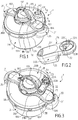
- the locking system is a bayonet locking system, making it possible to pass the apparatus 1 of a locking waiting configuration, in which the cover 3 is attached to the tank 2 and rests freely on the latter ( Figures 1 and 3 ), to a locking configuration in which the tank 2 and the lid 3 interact to prevent their free separation (cf. figure 7 and 8 ), and vice versa.
- the apparatus 1 moves from its locking waiting configuration to its locking configuration by rotation of the cover 3.
- the bayonet locking system of the cooking apparatus 1 advantageously comprises for this purpose first and second series of excrescences 7A-7J, 8A-8J which are secured respectively to the lid 3 and the bowl 2 and which are designed, to ensure the locking and unlocking of the cover 3 relative to the tank 2, to engage, respectively disengage, mutually by rotation of the cover 3 relative to the tank 2 about the central vertical axis XX 'according to said race predetermined angle.
- the protuberances 7A-7J, 8A-8J of each of said first and second series are intended to cooperate in pairs, that is to say that each protrusion of one of said series is brought, by rotation of the cover 3 relative to the tank 2, to pass under a corresponding protrusion of the other series to lock the cover 3 relative to the tank 2.
- the protuberances 7A-7J of the first series, integral with the cover 3 project radially inwardly of the cover 3
- the protuberances 8A-8J of the second series, integral with the tank 2 project radially from the outer face of the wall 2B side of the tank 2, to the outside of the latter.
- the locking protrusions 7A-7J of the cover protrude outwardly from the lid 3 and for the bowl protuberances 8A-8J to project radially towards the inside of the latter.
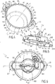
- the tank protuberances 8A-8J are formed by an annular flange projecting outwardly from the free upper edge 2C, the notches 9A-9J being formed through said annular flange so as to allow the passage of said protrusions 7A-7J cover, so that the portions of said annular flange extending between each notch 9A-9J form the respective tank ramps intended to cooperate with the protrusions 7A-7J cover which form the ramps of lid.
- the cover protrusions 7A-7J can pass through the notches 9A-9J for lower than the ring flange.
- the apparatus 1 is then in its pre-lock configuration (also referred to as the lock wait pattern), from which the lock pattern can be reached by simply rotating the lid 3 relative to the bowl 2 according to the vertical axis X-X ', which has the effect of angularly shift the protrusions 7A-7J of the cover 3 and the notches 9A-9J of the annular rim, performing a locking type " bayonet ".
- the cover protuberances 7A-7B are located on the annular belt 3B of the cover 3 at a distance from the second circular free edge 31B of said annular belt 3B, so that the belt 3B annulus forms, below said elements by volume, a skirt self-centering lid 3 relative to the tank 2.
- the apparatus 1 comprises a lid subassembly (illustrated in isolation by the figure 5 ) which includes both the cover 3 and a support 10 attached to said cover 3, in this case permanently, so that the latter can move relative to said support 10 between two positions respectively corresponding to an unlocking configuration and a locking configuration of said lid subset.
- the support 10 is attached to the cover 3 so that the latter can pivot relative to said support 10 between said two positions along the central vertical axis X-X '.
- the invention is however not limited to a rotational mounting of the cover 3 relative support 10.
- the locking system is for example a locking system with flexible cover
- the cover 3 can move in translation relative to the support, as described in the document EP-1 938 718 .
- the pivot connection between the cover 3 and the support 10 can be achieved by any known means.
- the two positions between which the lid 3 can pivot relative to the support 10 are separated by a predetermined angular stroke corresponding to that required to pass the device 1 of its pre-locking configuration (waiting configuration of lock) illustrated in figure 1 to its lock configuration illustrated for example to Figures 7 and 8 .
- the support 10 is, in the embodiment illustrated in the figures, in the form of a cross member, that is to say of a substantially elongate piece which extends diametrically on the cover 3 and which is extended in this case at each of its ends by respective falling edges 10A, 10B.
- the cross member in question comprises an enlarged central zone 100, for example of generally circular shape, extended on either side by a first arm 101 and a second arm 102 which themselves respectively terminate in said falling edges 10A. , 10B.
- the central portion 100 is advantageously provided with a central orifice 100A in which is intended to be threaded an axis 30 fixed on the lid 3, in the center of the latter, and around which the support 10 is intended to rotate along the vertical axis central X-X '.
- the axis 30 is provided with a threaded recess for cooperating with a screw 16 in order to fix the support 10 to the cover 3 while allowing the cover 3 to pivot about the axis 30.
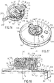
- the support 10 includes, in addition to the cross-piece shown at figure 10 , a plate 17 which has a substantially circular shape substantially complementary to that of the central portion 100 of the cross member and which is intended to be interposed between said cross member and the upper face of the cover 3 to form a housing intended to accommodate at least partially a control mechanism.
- the visible cross at the figure 10 is itself designed to be fixed (for example by means of several screws) permanently to the plate 17, in order to form with the latter a subassembly unitary cross member, monobloc, held on the cover 3 by means of the coupling 30 / screw 16, which coupling allows the pivoting of the lid 3 relative to the superstructure subassembly aforesaid forming the support 10.
- the apparatus 1 comprises at least one guide pin 18, and preferably two guide pins 18, 19 arranged diametrically opposite relative to the central axis XX 'and permanently attached to the lid 3.
- Each of said guide pins 18, 19 is designed to slide in a complementary elongate guide groove 18A, 19A formed in the support 10, for example towards each end of said support 10.
- the length of each groove 18A, 19A is adapted in this case to the angular travel of the cover 3 relative to the support 10.
- Each pin 18, 19 is further provided with an enlarged section head which cooperates with the edges of the corresponding groove 18A, 19A to vertically retain the support 10 and prevent it from moving vertically away from the lid 3.
- the lid subassembly and the bowl 2 are designed to be joined in at least one predetermined relative arrangement (illustrated for example in FIGS. Figures 1 and 3 ) allowing said locking system to lock the lid 3 to the tank 2 by moving the lid 3 relative to the support 10 to move the lid subassembly from its unlocking configuration to its locking configuration.
- the predetermined relative arrangement is in this case obtained by combining the tank 2 and the lid subassembly when the latter is in the unlocking configuration.
- said predetermined relative arrangement allows the bayonet locking system to lock the lid 3 to the bowl 2 by pivoting the lid 3 relative to the support 10 along said central vertical axis X-X '.
- the lid subassembly when the lid subassembly is in the unlocking configuration, the lid 3 and the support 10 are positioned relative to each other such that the docking of the support 10 on the tank 2 according to a predetermined position, corresponding to said predetermined relative arrangement, makes it possible to pass the cover ramps 7A-7J below the tank ramps 8A-8J by the notches 9A-9J separating said tank ramps 8A-8J, the subassembly cover then capping the tank 2 in a waiting position, from which it will be sufficient to rotate the lid 3 relative to the tank 2 to lock the lid 3 relative to the tank 2.
- the tank 2 and the lid subassembly in unlock configuration joined according to the predetermined relative pre-locking arrangement illustrated in FIG.
- figure 1 it suffices to hold the support 10 in position relative to the tank 2 and to pivot the lid 3 relative to the support 10 according to the aforementioned predetermined angular stroke in order to bring the lid ramps in correspondence with the tank ramps, under these last, thus locking the lid 3 relative to the tank 2.
- the apparatus 1 further comprises a control member 11 for locking / unlocking, designed in this case to be manipulated (in this case directly) by the user so as to allow the latter to control the locking system so to be able to pass, by manual actuation of the control member 11, the lid subassembly of its configuration of locking to its unlocking configuration and vice versa, thereby controlling the passage of the device 1 of its pre-locking configuration (also called locking waiting configuration - illustrated in FIG. figure 1 ) to its lock configuration (shown in figure 8 ), and vice versa.
- the support 10 is not designed to be manually operated to control the movement of the cover 3 between its locking and unlocking positions, this function being in this case devolved exclusively to the control member 11.
- the control member 11 is separate from the support 10, while being for example attached to said support 10, in this case permanently, so as to be movable manually relative to the latter between locking positions ( Figures 7 and 8 ) and unlocking ( figure 1 ) and vice versa.
- the support 10 advantageously permanently embeds the control member 11, which nevertheless retains an ability of mobility relative to said support 10.
- the apparatus 1 also comprises a device for transforming the displacement of the control member 11 pivoting the cover 3 relative to the support 10 along the central vertical axis X-X ', so that said locking and unlocking positions of the control member 11 respectively correspond to said locking and unlocking configurations of the sub-unit. cover set.
- the user can thus control the passage of the cover subassembly from its unlocking configuration to its locking configuration, and vice versa, by manual movement of the control member 11 relative to the support 10 between its unlocking and unlocking positions. locking, and vice versa.
- the transformation device which is particularly visible figures 9 and 12 to 17 is therefore designed to convert the movement of the control member 11 relative to the support 10 in rotary motion of the cover 3 relative to the same support 10, in this case along said central vertical axis X-X ', so that the The user can thus control the locking / unlocking by pivoting of the cover 3 relative to the support 10 by simple manipulation of the control member 11, once the cover 3 is attached to the tank 2 with the cover ramps located below the tank ramps. .
- the abovementioned transformation device is designed according to the nature of the displacement of the control member 11 relative to the support 10 and may implement any drive component (gear, cam, lever, rod, etc.) required.
- said control member 11 is pivotally mounted relative to said support 10 according to a radial pivot axis YY 'which is perpendicular to the central vertical axis X-X', and is secant thereto.
- the control member 11 can thus be in the form of a rotary member of the handle, lever, handle, handle ... It is however quite possible that the control member 11 is rather mounted relative to relatively support 10, and is for example in this case in the form of a sliding element such as a push button, a slider, etc.
- said transformation device comprises a gear reduction mechanism designed to drive the cover 3 in rotation about said central vertical axis XX 'in a path having a first predetermined angular amplitude a, in response to a rotation of said control member 11 around said radial axis.
- YY 'in a race having a second predetermined angular amplitude ⁇ greater than said first predetermined angular amplitude a.
- the control member 11 is designed to pivot about said radial axis YY 'between a raised position (corresponding to the unlocking) and a folded position (corresponding to the lock) separated by a stroke having a predetermined angular amplitude ⁇ of approximately 90 °, while the lid 3 pivots relative to the support 10, in response to the angular displacement of about 90 ° of the control member 11 relative to the support 10, in a stroke has a predetermined angular amplitude ⁇ of about 15 ° .
- the transformation device comprises a transmission piece 20 mounted to move in translation in a horizontal plane perpendicular to said central vertical axis XX 'relative to said support 10.
- the transformation device comprises a mechanism for transforming the pivoting movement of the control member 11 relative to the support 10 in translational movement of said transmission member 20 relative to said support 10.
- the transformation mechanism in question is formed by a cam 110, 111 integral with the control member 11, said cam 110, 111 being provided with a pin which is received in a corresponding housing formed in the transmission part 20, so that the pivoting of the control member 11 causes the concomitant rotation of the 210A, 210B, which then pushes the transmission piece 20 in the horizontal plane perpendicular to the central vertical axis X-X '.
- the transformation device comprises, in accordance with the embodiment illustrated in the figures, at least one horizontal lever 21 pivotally mounted relative to the support 10 according to an eccentric vertical axis ZZ 'which is fixed with respect to said support 10, parallel to said vertical axis central XX 'and located at a predetermined distance from the latter.
- said horizontal lever 21 extends longitudinally between a first end 21A hinged to the cover 3 and a second end 21B hinged either to said control member 11 or to a transmission part (such as for example the transmission 20 evoked above) which is part of the transformation device and which is driven in displacement relative to the support 10 by the control member 11, for example according to the embodiment described above.
- said horizontal lever 21 is pivotally mounted relative to the support 10 at a pivot point located between said first end 21A and the second end 21B, so that the eccentric vertical axis ZZ 'passes through an area of the horizontal lever 21 which is located at a distance from both the first and second ends 21A, 21B.
- the articulation of the first end 21A relative to the lid 3 is for example made by means of a first pin 210A which is integral with the lid 3 so as to rise vertically from the latter.
- Said pin 210A is advantageously received in a first corresponding groove formed at the first end 21A of the horizontal lever 21, so that said first pin 210A can both slide and rotate in the first groove in question.
- the conversion device also advantageously comprises a second pin 210B which is in this case secured to the transmission part 20 and embarked on the latter.
- Said second pin 210B is advantageously received in a second complementary groove formed at the second end 21B of the horizontal lever 21, so that said second pin 210B can both slide and pivot in the second groove in question.
- the displacement in rectilinear translation of the transmission part 20 in the horizontal plane is thus converted into rotation of the lever 21 about the eccentric vertical axis Z-Z ', which rotation is itself converted into a rotation of the lid 3 relative to the support 10 along the central vertical axis X-X '.
- control member 11 comprises a handle 11A to be manually actuated so that it can be moved manually by a user between two preferably stable stop positions, respectively corresponding to the locking and unlocking.
- the control member 11 is therefore in the form of an arched, loop-shaped, arched piece, advantageously designed to be grasped firmly, preferably by hand, by a user. .
- control member 11 is mounted pivotally relative to said support 10 between on the one hand an extended position ( figure 1 ) which forms said unlocking position and wherein said control member 11 protrudes vertically, in this case to the right of the cover 3 outwards, and secondly a retracted position which forms said locking position and in which said control member 11 is lowered towards the cover 3.
- control member 11 In its deployed position, the control member 11 advantageously extends in a mean direction substantially parallel to said central vertical axis X-X ', whereas in its retracted position it advantageously extends in a mean direction substantially perpendicular to said central vertical axis X-X ', as illustrated in the figures.
- the support 10 and the tank 2 are designed to interact, directly or indirectly, when the cover subassembly in the unlocking configuration and the tank 2 are joined in accordance with said predetermined relative arrangement, in order to substantially prevent the support 10 from ability to pivot relative to the vessel 2 (in this case along said central vertical axis X-X ') when the control member 11 is moved between its locking and unlocking positions (or conversely).
- the meeting of the lid subassembly in the unlocking configuration and the tank 2 according to the predetermined relative arrangement (pre-locking arrangement) illustrated in FIG. figure 1 causes an inter-locking of the support 10 and the tank 2 preventing in this case the support 10 to rotate along the central vertical axis XX 'while resting on the tank 2.
- This locking of the relative angular position of the support 10 and of the tank 2 allows the support 10 to act as a stationary fixed frame relative to the tank 2 and relative to which the cover 3 can pivot about the central vertical axis XX 'in a predetermined angular stroke to pass from an unlocked state (shown at figure 1 ) to a locked state (shown in figure 16 ).
- the support 10 protrudes radially from the lid 3 so as to interact with the tank 2 to substantially immobilize in rotation along the vertical axis the support 10 relative to the tank 2 when the lid subassembly and the tank 2 are joined. according to said predetermined relative arrangement.
- said support 10 and tank 2 are respectively provided with complementary support conformations 12, 13 and 14, designed to cooperate by interlocking when the locking configuration of the lid subassembly and the tank 2 are joined according to said predetermined relative arrangement for forming the cooking chamber ( figure 1 ).
- the tank 2 is provided with two tank conformations 14, 15 arranged diametrically opposite relative to the central vertical axis XX 'and fixed on the external face of the side wall 2B of the tank.
- the support 10 has two complementary support conformations 12, 13 arranged diametrically opposite on the cover 3 relative to the central vertical axis X-X ', said supporting formations 12, 13 being in this case arranged opposite the outer face of the annular belt 3B of the cover 3.
- each tank conformation 14, 15 forms a male element while each support conformation 12, 13 forms a complementary female element of said male element, said male element being advantageously intended to be inserted into said female element to establishing a locking link in rotation along the central vertical axis XX 'between the support 10 and the tank 2.
- said tank conformation 14, 15 is carried by said handle 2D, 2E.
- each handle 2D, 2E permanently fixed to the side wall 2B of the tank 2, embeds a tank conformation 14, 15 respectively, which is for example under the form of a rib forming a male element.
- a notch is advantageously formed in the free lower edge of each of said falling edges 10A, 10B of the support 10, to form a female element complementary to the rib preferably forming the male element.
- the lid subassembly comprises a first device 22 and a second device 23, the latter being capable, provided that said first and second devices 22, 23 are separated by a distance D n ' exceeding a predetermined value, to exert an influence on the first device 22 so that said device 22 delivers in response an information signal and / or control, for example of electrical nature.
- the lid subassembly embodies, permanently or removably, said first and second devices 22, 23, which are designed to interact according to a predetermined functional connection as soon as they are sufficiently close to one another. on the other, that is to say that as soon as the distance D mutually separating them is less than or equal to a threshold corresponding to said predetermined value referred to above.
- said support 10 and cover 3 respectively embark the one and the other of said first and second devices 22, 23.
- any one of said first and second devices 22, 23 is integral with the support 10, while the other is secured to the lid 3, so that said first and second devices 22, 23 move relative to each other. the other when the lid 3 moves relative to the support 10.
- the support 10 embeds the first device 22, while the lid 3 embeds the second device 23. It is however quite possible, without, however, departing from the scope of the invention, the support 10 rather embeds the second device 23 and the cover 3 then embeds the first device 22.
- said support 10 and cover 3 respectively embark both of said first and second devices 22, 23 so that when said lid subassembly is in a locking configuration (illustrated in FIG. figure 8 ), said first and second devices 22, 23 are separated by a distance D that does not exceed said predetermined value, and that when said lid subassembly is in the unlocking configuration (illustrated in FIG. figure 6 on the contrary, said first and second devices 22, 23 are separated by a distance D which exceeds said predetermined value.
- the distance D separating said first and second devices 22, 23 varies between a first value which does not exceed said predetermined value ( Figures 7 and 8 ) and a second value which exceeds said predetermined value ( Figures 1 and 3 ).
- the invention is based on the idea of using a relative movement of the cover 3 and the support 10 to pass a first device 22, which is for example integral with the support 10, a first deactivated state or inactivable to a second state activated or activatable by simply bringing said first device 22 with a second device 23 which advantageously plays the role of activator element or exciter.
- This change of state of the first device in response to the influence exerted by the second device 23, made possible by the bringing together of said first and second devices 22, 23, is used to cause the first device 22 to deliver a signal, that is to say a physical phenomenon of any kind (electrical, electromagnetic, sound, light ...) carrying information, to use this information is directly to inform the l user, either to control the operation of the device 1 itself or an external device (hob, computer terminal such as a smartphone or a touch pad ).
- the second device 23 when the lid subassembly is in the configuration of locking, the second device 23 is found positioned relative to the first device 22 so as to immediately exert an influence on the first device 22 so that the latter delivers in response said information signal and / or control, or to be able to exercise said influence at a later time, for example when other conditions (such as reaching a predetermined value of pressure within the cooking chamber) will be met.
- the invention therefore uses the displacement of the cover 3 relative to the support 10 to develop, by means of the first device 22, a usable signal, either directly (if it is for example a light or sound information signal) or indirectly (if it is for example an electrical signal intended to be processed to exploit it for information or control purposes).
- the first device 22 is carried by the support 10, that is to say it is attached to and against said support 10, while said second device 23 is carried by said cover 3 , so that said second device 23 is directly attached to the outer face of said cover 3, for example on the discoid cover member 3A.
- the first device 22 is formed by an independent module 24 (shown separately in FIG. figure 2 ) adapted to be removably attached to said support 10, so that a user of the apparatus 1 can at will, and preferably without tools other than his hands alone, attach said independent module 24 to said support 10 and detach it from this last.
- said independent module 24 and support 10 are provided with complementary fastening means 25, 26 respectively designed to cooperate to removably attach the independent module 24 to the support 10.
- This cooperation can be of any kind.
- the complementary fastening means 25, 26 may be designed to cooperate by magnetic attraction (which constitutes a separate and independent invention as such), in which case the fastening means 26 associated with the support 10 is for example formed by a magnet while the independent module 24 embeds a ferromagnetic substance capable of being attracted by the magnet in question.
- the cooperation between the complementary attachment means 25, 26 is of a mechanical nature, as in the example illustrated in the figures, where the independent module 24 is designed to be fixed on the support 10 by clipping, that is to say by interlocking by force of a male element forming in this case the attachment means 26 of the support and a female element forming in this case the attachment means 25 of the independent module 24 (or vice versa).
- the complementary attachment means 25, 26 are advantageously designed to completely immobilize the first device 22 on the support 10, that is to say that they are designed to make a connection between the support 10 and the first 22.
- the first device 22 is fixed to the support 10 with a mobility faculty, and / or that it is attached permanently, irremovable, to the support 10.
- the apparatus 1 comprises at least one processing unit designed to exploit the information and / or control signal, in order to elaborate, from said signal which is preferably electrical in nature as mentioned above, intelligible information. by a user and / or a control command to control the operation of the apparatus 1 itself or an external device as mentioned above.
- said processing unit is advantageously integrated in the independent module 24.
- the processing unit it is quite possible for the processing unit to be distinct from said independent module 24, or even to be totally deported. of the apparatus 1, in which case the first device 22 is advantageously designed to communicate via a wired or wireless link (for example by radio waves) with the processing unit.
- the apparatus 1 comprises several processing units, one of which is embedded by the independent module 24 and the other on board by an external device advantageously formed by an ordiphone capable of communicating, for example by a link Bluetooth ®, with the independent module 24.
- the processing unit is designed to exploit said information signal and / or control to develop information, the device 1 also comprising display means 27, such as for example a screen (for example an LCD screen, tactile or not), a display or a dial, which is connected to said processing unit by an appropriate functional link, wired or not, to display said information and make it thus accessible and intelligible to the user of the apparatus 1.
- the invention is however not absolutely limited to the implementation of an independent module 24 e equipped with a display means 27, and it is for example quite conceivable, without departing from the scope of the invention, the independent module 24 is devoid of any display means, the latter being offset on an independent external terminal (and for example formed by the screen of a smartphone) which communicates by a wireless link with the independent module 24.
- said first device 22 includes a sensor 22A designed to produce said information and / or control signal from a physical quantity value that the distance D between said first and second devices 22, 23 is likely to vary. .
- the sensor 22A is designed to measure a physical quantity in a zone of the predetermined space, preferably corresponding to the position of the sensor 22A in question.
- the second device 23 is too far from the sensor 22A so that the physical quantity measured by said sensor can vary significantly.
- the second device 23 is then capable of varying said physical quantity sufficiently significantly. in the detection zone of the sensor 22A so that the latter is capable of producing said information and / or control signal.
- said sensor 22A is a temperature sensor
- said second device 23 comprises an orifice 23A formed through the cover 3 to allow the temperature sensor 22A to be accessed, when said lid subassembly is in position. lock configuration, the temperature prevailing within the device 1, or an image of the latter.
- the temperature sensor 22A is designed to elaborate said information and / or control signal from a temperature value that the distance between the sensor 22A and the orifice 23A formed through the lid 3 is likely to vary.
- the temperature sensor 22A is too far from the orifice 23A for the The temperature value measured by the sensor 22A can be influenced, even temporarily, significantly.
- the sensor 22A is sufficiently close to the orifice 23A for the temperature value it measures to be directly a function of the temperature prevailing in the appliance 1 , that is to say prevailing within the cooking chamber formed by the lid 3 and the tank 2.
- said second device 23 forms a pressure regulating device 4 designed to prevent the pressure inside the device 1 from exceeding a predetermined setpoint, called "operating pressure ", which exceeds the atmospheric pressure of a device.
- a value which is for example between substantially 10 and 120 kPa, and which is preferably of the order of 100 kPa.
- the general operating principle of such a pressure regulating means is well known as such.
- said pressure regulating member includes a valve associated with said orifice 23A formed through the cover 3, said valve including itself a shutter 40 movable between a closed position, in which it prevents the vapor contained within the apparatus 1 to escape from the apparatus 1, that is to say in this case out of the cooking chamber, through the orifice 23 A, and an open position, in which it authorizes the vapor contained within the apparatus 1 to escape out of the latter through the orifice 23A and according to a predetermined escape path.
- the valve forming in this case the pressure regulating member 4 comprises a valve seat 41 which is in the form of a substantially tubular duct terminated at the orifice 23A and s' rising substantially vertically, along an axis W-W ', to a free upper end that the shutter 40 closes or release depending on the pressure level prevailing within the cooking chamber.
- the valve forming the pressure regulating member 4 includes a return means adapted to exert a restoring force on the shutter 40, in order to keep it in its closed position as long as the pressure level prevailing at the within the cooking chamber is less than or equal to a predetermined level P0, corresponding to the operating pressure.
- the return means is designed so that as soon as the pressure prevailing within the cooking chamber exceeds the operating pressure P0, the steam exerts on the shutter 40 a driving force which is sufficient to overcome the restoring force and move the shutter 40 away from the seat 41, to allow the steam contained in the cooking chamber to escape through the orifice 23A and the seat 41 to the outside.
- the return force in question may be for example exerted by a spring or simply by the weight of the shutter 40.
- said valve is provided with a steam channeling member designed to impart to the steam s' escaping from the aircraft a substantially vertical escape path from bottom to top.
- the pipe member in question is formed by the seat 41, through which the steam escapes along an upward vertical path, parallel to the axis WW '(itself parallel to the vertical central axis X-X ') when the shutter 40 is pushed back into its open position.
- said temperature sensor 22A is designed to be on said steam escape trajectory, when said lid sub-assembly is in a locking configuration, to determine the temperature of the vapor at its outlet from the appliance. 1.
- the temperature sensor 22A is intended to overhang said valve forming the pressure regulating member 4, when said lid sub-assembly is in a locking configuration, so that the temperature sensor 22A is then on the axis WW 'of symmetry of the seat 41, vertically and above the orifice 23A of the seat 41.
- the lid subassembly is located in the unlocking configuration (cf.
- the temperature sensor 22A is angularly offset relative to said axis W-W ', so that it substantially does not cross the exhaust path of the steam and is therefore not able to reliably determine the temperature of the steam at the outlet of the valve.
- the steam channeling member comprises not only said seat 41, upstream of the movable shutter 40, but also a downstream channeling member 42, which has substantially a tubular shape and extends substantially upward from the upper end of the seat 41.
- the apparatus 1 comprises a timer functionally connected to said temperature sensor 22A, which is designed to detect a rise in temperature following a steam escape resulting from the passage of the shutter 40 in the open position, and to transmit in return a trigger signal of said timer.
- the temperature information collected by the sensor 22A is advantageously used by said processing unit to trigger the counting of a cooking time by a timer functionally connected to the sensor 22A.
- the processing unit is for example designed to detect the significant variation in temperature resulting from the escape of the very first jet of steam when the predetermined pressure P0 has just been exceeded for the first time, in order to trigger at this moment the countdown.
- the timer in question is advantageously embedded in the independent module 24, which is provided with control means (for example buttons) allowing a user to set the cooking time counted by the timer to the value of his choice, the screen 27 can display the value in question then the count of this value when the time comes.
- said valve forming the pressure regulating member 4 advantageously has, in the vertical direction W-W ', an overall height H which is substantially invariable, in order not to changing the distance vertically separating the top of the valve (corresponding in this case to the top of the downstream channeling member 42) of the sensor 22A, when the lid subassembly is in the locking configuration.
- the first device 22 advantageously comprises an annular element 22B delimiting an interior space 22C (cf. figure 2 ) which is surrounded by said annular element 22B and which accommodates said temperature sensor 22A, to protect the latter from any air currents that could disturb the measurement, and to limit the lateral loss of steam.
- the annular element 22B also makes it possible to protect the temperature sensor 22B against possible shocks (in the event of a fall, for example).
- the annular element 22B thus advantageously forms a loop which extends substantially in a horizontal mean plane perpendicular to the central vertical axis X-X ', the sensor 22A forming a protrusion which extends inwardly of said loop until in the center of the latter, so that the active portion of said sensor 22A is found substantially in the center of said loop formed by the annular element 22B.
- the axis of symmetry of the orifice 23A passes through said center of said loop, and therefore by the sensor 22A, and more specifically by the active part of the latter.
- the first device 22 comprises a main body 220 (cf. figure 2 ) which carries said temperature sensor 22A and annular element 22B so that they protrude laterally from said main body 220, cantilevered, to overhang the lid 3.
- the main body 220 accommodates a display means 27 (for example an LCD screen on its upper face) as well as a timer that can be parameterized by means of control buttons also carried by the main body 220.
- An independent module 24 comprising a temperature sensor 22A as well as an annular element 22B delimiting an interior space 22C which is surrounded by said annular element 22B and which accommodates said temperature sensor 22A, as illustrated in FIG. figure 2 for example, constitutes as such an independent invention.
- the invention is not limited to the implementation of a sensor 22A which is a temperature sensor.
- the sensor 22A may be for example a magnetic sensor, in which case the second device 23 advantageously incorporates a magnetic element designed to excite the magnetic sensor in question when the distance D between said first and second devices 22, 23 does not exceed said predetermined value, so that said sensor 22A responds in response to said information and / or control signal.
- the first and the second devices 22, 23 are designed to interact magnetically when the lid subassembly is in position. locking configuration, this magnetic interaction being advantageously a remote interaction.
- the senor 22A can be constituted in this case by a magneto-resistive sensor, for example of C-MOS type, while the magnetic element comprises a magnet, for example a permanent magnet.
- the sensor 22A is a contact sensor, in which case said second device 23 advantageously incorporates an actuator intended to come into contact with said sensor 22A, when the lid subassembly found in locking configuration, in order to actuate said sensor 22A, in this case in contact with the latter, so that said sensor 22A responds in response to said information signal and / or control.
- the first device 22 is for example provided with a switch forming the sensor 22A, said second device 23 being designed to press said switch when the lid subassembly goes into a locking configuration, in order to thus to switch the switch in question from a deactivated state to an activated state.
- the invention is absolutely not limited to a specific interaction between said first and second devices 22, 23, this interaction being electrical, thermal, optical, magnetic ... the essential being that the movement of the lid 3 relative to the support 10 is used to obtain an information signal and / or control.
- the apparatus 1 comprises an opening security means 5 distinct from said first and second devices and capable of changing, under the effect of the pressure level prevailing in the apparatus 1, between a release configuration, in which it allows the unlocking of the cover 3 relative to the tank 2, and a locking position, in which it prevents the unlocking of the lid 3 relative to the tank 2.
- said security means 5 advantageously comprises a movable element 5A slidably mounted on the cover 3, and in this case vertical sliding in a sliding direction parallel to the central vertical axis X-X ', between a high position (abutment) in which it is able to cooperate with a complementary blocking element 5B carried by the support 10, in order to block the displacement of the cover 3 relative to the support 10, and a low position (stop) in which it does not not interfere with the complementary element 5B, thereby allowing the cover 3 to move relative to the 10.
- the movable element 5A is advantageously formed by a finger intended to slide vertically within a tube terminated at a leakage orifice formed through the lid 3, so that in the high position the finger comes to seal the orifice hermetically leakage, while in the low position the steam is allowed to leak through the orifice in question.
- Complementary element 5B is preferably formed by a part having a stop surface 50B and a through hole 51B.
- the blocking surface 50B is located at the right of the mobile element 5A, on the sliding path of the latter, in order to prevent it from reaching its high position and thus maintain a communication between the inside of the cooking chamber and the outside, preventing any significant rise in pressure of the chamber.
- the lid 3 reaches its locking position, by pivoting relative to the support 10 according to the predetermined angular stroke mentioned above, the movable element 5 is then found at the right of the opening 51B, which allows the movable element 5A to achieve, under the effect of the driving force exerted by the rise in pressure within the cooking chamber, its upper sealing position.
- the movable member 5A is surrounded by the edges of the orifice 51B, which prevents any pivoting of the cover 3 relative to the support 10 in the unlocking direction.
- the operation of the cooking appliance 1 illustrated in the figures will now be briefly described.
- the user first fills the tank 2 illustrated in FIG. figure 4 of food to be cooked, possibly positioning the food away from the bottom of the tank 2, in a perforated cooking basket.
- the user grabs the lid subassembly (shown in figure 5 ) by the handle 11A for lifting said subassembly for the return to the tank 2 to close the latter.
- the user thus combines the lid subassembly in the unlocking configuration and the tank 2 according to the predetermined relative arrangement illustrated in particular in FIG. figure 1 .
- the temperature sensor 22A and the axis WW 'of the valve are angularly offset, as illustrated in FIG. figure 3 .
- the sensor 22A is not able to correctly detect the temperature variation corresponding to the exhaust of the first Steam fumaroles when the set pressure P0 is reached. Then the user folds the handle 11A in an angular stroke ⁇ of about 90 °, until reaching a folded abutment position illustrated in particular in Figures 7 and 8 .
- This movement of the handle 11A from its extended position to its folded position causes the lid 3 to pivot relative to the support 10 by an angle ⁇ of approximately 15 °, allowing the lid ramps to come into correspondence under the tank ramps. in a locking configuration allowing the rise in pressure.
- the pivoting of the cover 3 relative to the support 10 simultaneously causes the displacement of the valve relative to the support 10 and to the sensor 22A, so as to bring said valve under said sensor 22A, the latter then being in the exhaust path of the steam .
- the cooking cycle can then begin.
- the pressure inside the cooking chamber reaches the set point P0, the steam escapes for the first time through the outlet duct of the valve formed by the seat 41 and the downstream duct member 42. thus scanning the sensor 22A which then detects this sudden rise in temperature and delivers a feedback control signal from the timer embedded in the independent module 24, which in this case also the temperature sensor 22A.
- the user At the end of the cooking cycle, and once the pressure within the chamber has fallen back to a predetermined safety level, the user only has to raise the handle 11A to rotate the cover 3 relative to the support 10 in the opposite direction and thus disengage the tank and lid ramps, allowing the separation of the lid 3 and the tank 2.
Landscapes
- Engineering & Computer Science (AREA)
- Food Science & Technology (AREA)
- Cookers (AREA)
Claims (15)
- Gerät (1) zum Garen von Nahrungsmitteln unter Druck, umfassend einen Behälter (2), einen Deckel (3) sowie ein Verriegelungssystem, wobei das genannte Gerät dadurch gekennzeichnet ist, dass es eine Deckel-Untereinheit umfasst, die gleichzeitig den Deckel (3) und einen Träger (10) enthält, der an dem Deckel (3) derart befestigt ist, dass sich Letzterer relativ zum Träger (10) zwischen zwei Positionen verschieben kann, die jeweils einer Entriegelungskonfiguration und einer Verriegelungskonfiguration der genannten Deckel-Untereinheit entsprechen, wobei die Deckel-Untereinheit und der Behälter (2) gestaltet sind, um gemäß wenigstens einer vorbestimmten relativen Anordnung vereint zu sein, die dem Verriegelungssystem das Verriegeln des Deckels (3) am Behälter (2) per Verschieben des Deckels (3) relativ zum Träger (10) erlaubt, um die Deckel-Untereinheit von ihrer Entriegelungskonfiguration in ihre Verriegelungskonfiguration übergehen zu lassen, wobei die Deckel-Untereinheit eine erste Vorrichtung (22) sowie eine zweite Vorrichtung (23) umfasst, die unter der Bedingung, dass die erste und zweite Vorrichtung (22, 23) um einen Abstand (D) getrennt sind, der einen vorbestimmten Wert nicht überschreitet, in der Lage ist, einen Einfluss auf die erste Vorrichtung (22) auszuüben, damit diese Letztere als Antwort ein Informations- und/oder ein Steuersignal ausgibt, wobei der Träger (10) und der Deckel (3) jeweils jeder die erste und zweite Vorrichtung (22, 23) aufnehmen, damit, wenn die Deckel-Untereinheit sich in der Verriegelungskonfiguration befindet, die erste und zweite Vorrichtung (22, 23) um einen Abstand (D) getrennt sind, der den vorbestimmten Wert nicht überschreitet, und damit, wenn die Deckel-Untereinheit sich in der Entriegelungsvorrichtung befindet, die erste und zweite Vorrichtung (22, 23) um einen Abstand (D) getrennt sind, der den vorbestimmten Wert überschreitet.
- Gerät (1) nach Anspruch 1, dadurch gekennzeichnet, dass die erste Vorrichtung (22) von dem Träger (10) getragen ist, während die zweite Vorrichtung (23) von dem Deckel (3) getragen ist.
- Gerät (1) nach Anspruch 2, dadurch gekennzeichnet, dass die erste Vorrichtung (22) durch ein unabhängiges Modul (24) geformt ist, das gestaltet ist, um abnehmbar an dem Träger (10) befestigt zu sein, wobei das unabhängige Modul (24) und der Träger (10) bevorzugt mit jeweiligen komplementären Befestigungsmitteln (25, 26) versehen sind, die gestaltet sind, um mittels magnetischer Anziehungskraft zusammenzuwirken, um das unabhängige Modul (24) am Träger (10) zu befestigen.
- Gerät (1) nach einem der Ansprüche 1 bis 3, dadurch gekennzeichnet, dass die erste Vorrichtung (22) einen Sensor (22A) einschließt, der zum Erarbeiten des Informations- und/oder Steuersignals ausgehend von einem physischen Größenwert gestaltet ist, den der Abstand (D) zwischen der ersten und zweiten Vorrichtung (22, 23) variieren kann.
- Gerät (1) nach Anspruch 4, dadurch gekennzeichnet, dass der Sensor (22A) ist:- entweder ein magnetischer Sensor, in diesem Fall beinhaltet die zweite Vorrichtung (23) ein magnetisches Element, das zum Erregen des Sensors (22A) gestaltet ist, wenn der die erste und zweite Vorrichtung (22, 23) trennende Abstand den vorbestimmten Wert nicht überschreitet, damit der Sensor (22A) als Antwort das Informations- und/oder Steuersignal erarbeitet,- oder einen Kontaktsensor, in diesem Fall beinhaltet die zweite Vorrichtung (23) ein Stellglied, das dazu bestimmt ist, mit dem Sensor (22A) in Kontakt zu kommen, wenn die Deckel-Untereinheit sich in der Verriegelungskonfiguration befindet, um den Sensor (22A) zu betätigen, damit dieser als Antwort das Informations- und/oder Steuersignal erarbeitet.
- Gerät (1) nach Anspruch 4, dadurch gekennzeichnet, dass der Sensor (22A) ein Temperatursensor ist, während die zweite Vorrichtung (23) eine Öffnung (23A) umfasst, die durch den Deckel (3) ausgespart ist, um dem Temperatursensor (22A) zu erlauben, auf die innerhalb des Geräts (1) herrschende Temperatur oder auf ein Bild derselben zuzugreifen, wenn die Deckel-Untereinheit sich in der Verriegelungskonfiguration befindet.
- Gerät (1) nach Anspruch 6, dadurch gekennzeichnet, dass die zweite Vorrichtung (23) ein Druckregulierungsorgan (4) bildet, das gestaltet ist, um zu verhindern, dass der innerhalb des Geräts herrschende Druck einen vorbestimmten Schwellenwert übersteigt.
- Gerät (1) nach Anspruch 7, dadurch gekennzeichnet, dass das Druckregulierungsorgan (4) ein Ventil enthält, das der durch den Deckel (3) ausgesparten Öffnung (23A) zugeordnet ist, wobei das Ventil selbst einen Verschluss (40) enthält, der zwischen einer Verschlussposition, in der er den innerhalb des Geräts (1) enthaltenen Dampf am Austreten durch die Öffnung (23A) aus dem Gerät (1) hindert, und einer Öffnungsposition mobil ist, in der er der innerhalb des Geräts (1) enthaltenen Dampf erlaubt, durch die Öffnung (23A) aus demselben gemäß einer vorbestimmten Austrittsbahn auszutreten, wobei der Temperatursensor (22A) gestaltet ist, um sich auf der Austrittsbahn zu befinden, wenn die Deckel-Untereinheit sich in der Verriegelungskonfiguration befindet, um die Temperatur des Dampfes an seinem Austritt aus dem Gerät (1) zu bestimmen, wobei das Ventil bevorzugt mit einem Kanalisationsorgan des Dampfes versehen ist, das gestaltet ist, um dem Dampf, der aus dem Gerät (1) austritt, eine deutlich vertikale Austrittsbahn von unten nach oben zu ermöglichen, wobei der Temperatursensor (22A) bevorzugt dazu bestimmt ist, das Ventil zu überragen, wenn die Deckel-Untereinheit sich in der Verriegelungskonfiguration befindet.
- Gerät (1) nach Anspruch 8, dadurch gekennzeichnet, dass das Ventil gemäß der vertikalen Richtung (W-W') eine deutlich invariable Höhe über alles (H) aufweist.
- Gerät (1) nach einem der Ansprüche 6 bis 9, dadurch gekennzeichnet, dass die erste Vorrichtung (22) ein ringförmiges Element (22B) aufweist, das einen Innenraum (22C) begrenzt, der durch das ringförmige Element (22B) umgeben ist und der den Temperatursensor (22A) aufnimmt, wobei die erste Vorrichtung (22) bevorzugt einen Hauptkörper (220) umfasst, der den Temperatursensor (22A) und das ringförmige Element (22B) derart trägt, dass sie bevorzugt lateral aus dem Hauptkörper (220) als Auskragung hervorstehen, um den Deckel (3) zu überragen.
- Gerät (1) nach einem der Ansprüche 1 bis 10, dadurch gekennzeichnet, dass das genannte Verriegelungssystem ein Bajonett-Verriegelungssystem ist, wobei der Träger (10) an dem Deckel (3) derart befestigt ist, dass Letzterer relativ zum Träger (10) zwischen den zwei Position gemäß einer zentralen vertikalen Achse (X-X') schwenken kann, wobei die vorbestimmte relative Anordnung dem Bajonett-Verriegelungssystem das Verriegeln des Deckels (3) an dem Behälter (2) durch Schwenken des Deckels (3) relativ zum Träger (10) gemäß der zentralen vertikalen Achse (X-X') erlaubt.
- Gerät (1) nach Anspruch 11, dadurch gekennzeichnet, dass es ein Steuerorgan (11) der Verriegelung/Entriegelung umfasst, das derart an dem Träger (10) befestigt ist, dass es per Hand relativ zu Letzterer zwischen der Verriegelungs- und der Entriegelungsposition verschoben werden kann, wobei das Gerät (1) eine Umwandlungsvorrichtung der Verschiebung des Steuerorgans (1) durch Verschieben des Deckels (3) relativ zum Träger (10) gemäß der zentralen vertikalen Achse (X-X') umfasst.
- Gerät (1) zum Garen von Nahrungsmitteln unter Druck nach Anspruch 12, dadurch gekennzeichnet, dass das Steuerorgan (11) schwenkbar relativ zum Träger (10) gemäß einer radialen Schwenkachse (Y-Y') montiert ist, die senkrecht zur zentralen vertikalen Achse (X-X') ist, wobei das Steuerorgan (11) bevorzugt einen Griff (11A) umfasst.
- Gerät (1) zum Garen von Nahrungsmitteln unter Druck nach einem der Ansprüche 12 und 13, dadurch gekennzeichnet, dass der Träger (10) und der Behälter (2) gestaltet sind, um zu interagieren, sobald die Deckel-Untereinheit in Entriegelungskonfiguration und der Behälter (2) gemäß der vorbestimmten relativen Anordnung vereint sind, um den Träger (10) deutlich daran zu hindern, relativ zum Behälter (2) zu schwenken, wenn das Steuerorgan (11) zwischen seiner Entriegelungs- und Verriegelungsposition verschoben ist.
- Gerät (1) zum Garen von Nahrungsmitteln unter Druck nach einem der Ansprüche 1 bis 14, dadurch gekennzeichnet, dass es ein Sicherheitsmittel an der Öffnung (5) umfasst, das von der ersten und zweiten Vorrichtung unterschiedlich ist und sich unter der Wirkung des in dem Gerät herrschenden Druckpegels zwischen einer Freisetzungskonfiguration, in der es das Entriegeln des Deckels (3) relativ zum Behälter (2) erlaubt, und einer Sperrposition, in der es das Entriegeln des Deckels (3) relativ zum Behälter (2) verbietet, ändern kann, wobei das Sicherheitsmittel (5) bevorzugt ein mobiles Element (5A) umfasst, das gleitend auf dem Deckel (3) zwischen einer hohen Position, in der es geeignet ist, mit einem komplementären Sperrelement (5B) zusammenzuwirken, das von dem Träger (10) getragen ist, um das Verschieben des Deckels (3) relativ zum Träger (10) zu sperren, und einer niedrigen Position, in der es nicht mit dem komplementären Element eingreift, wodurch das Verschieben des Deckels (3) relativ zum Träger (10) erlaubt wird.
Applications Claiming Priority (1)
| Application Number | Priority Date | Filing Date | Title |
|---|---|---|---|
| FR1555110A FR3036938B1 (fr) | 2015-06-04 | 2015-06-04 | Autocuiseur equipe d'un support et d'un couvercle mobile relativement audit support |
Publications (2)
| Publication Number | Publication Date |
|---|---|
| EP3100656A1 EP3100656A1 (de) | 2016-12-07 |
| EP3100656B1 true EP3100656B1 (de) | 2019-08-28 |
Family
ID=54937158
Family Applications (1)
| Application Number | Title | Priority Date | Filing Date |
|---|---|---|---|
| EP16171508.1A Active EP3100656B1 (de) | 2015-06-04 | 2016-05-26 | Schnellkochtopf mit einer unterstützung und einem bewegbaren deckel |
Country Status (3)
| Country | Link |
|---|---|
| EP (1) | EP3100656B1 (de) |
| CN (1) | CN106235878B (de) |
| FR (1) | FR3036938B1 (de) |
Families Citing this family (19)
| Publication number | Priority date | Publication date | Assignee | Title |
|---|---|---|---|---|
| FR3049840B1 (fr) * | 2016-04-08 | 2019-04-05 | Seb S.A. | Autocuiseur pourvu d'une ouverture de couvercle |
| US11583128B2 (en) | 2017-06-21 | 2023-02-21 | Foshan Shunde Midea Electrical Heating Appliances Manufacturing Co., Ltd. | Cooking appliance |
| DE202018006410U1 (de) | 2017-08-09 | 2020-04-23 | Sharkninja Operating Llc | Kochgerät und Komponenten davon |
| CN109124328B (zh) * | 2017-08-10 | 2025-05-02 | 武汉苏泊尔炊具有限公司 | 锅盖及具有其的压力锅 |
| CN107752777A (zh) * | 2017-08-29 | 2018-03-06 | 浙江尚厨炊具有限公司 | 微压锅及其锅盖插接机构 |
| CN108175257B (zh) * | 2017-12-26 | 2020-09-08 | 重庆凡匠科技有限公司 | 一种食材烹饪设备的密封结构 |
| CN107951414B (zh) * | 2017-12-27 | 2024-06-28 | 唐锋机电科技(深圳)有限公司 | 搅拌料理机 |
| USD914447S1 (en) | 2018-06-19 | 2021-03-30 | Sharkninja Operating Llc | Air diffuser |
| CN110772115B (zh) * | 2018-07-30 | 2025-05-27 | 武汉苏泊尔炊具有限公司 | 锅盖及包括该锅盖的烹饪器具和压力锅 |
| USD883014S1 (en) | 2018-08-09 | 2020-05-05 | Sharkninja Operating Llc | Food preparation device |
| USD903413S1 (en) | 2018-08-09 | 2020-12-01 | Sharkninja Operating Llc | Cooking basket |
| USD934027S1 (en) | 2018-08-09 | 2021-10-26 | Sharkninja Operating Llc | Reversible cooking rack |
| USD883015S1 (en) | 2018-08-09 | 2020-05-05 | Sharkninja Operating Llc | Food preparation device and parts thereof |
| WO2020176477A1 (en) | 2019-02-25 | 2020-09-03 | Sharkninja Operating Llc | Cooking system with guard |
| US20190254476A1 (en) | 2019-02-25 | 2019-08-22 | Sharkninja Operating Llc | Cooking device and components thereof |
| USD918654S1 (en) | 2019-06-06 | 2021-05-11 | Sharkninja Operating Llc | Grill plate |
| USD982375S1 (en) | 2019-06-06 | 2023-04-04 | Sharkninja Operating Llc | Food preparation device |
| US11647861B2 (en) | 2020-03-30 | 2023-05-16 | Sharkninja Operating Llc | Cooking device and components thereof |
| FR3156296A1 (fr) * | 2023-12-11 | 2025-06-13 | Seb S.A. | Appareil électrique de préparation culinaire |
Family Cites Families (11)
| Publication number | Priority date | Publication date | Assignee | Title |
|---|---|---|---|---|
| FR2722078B1 (fr) | 1994-07-06 | 1996-08-30 | Seb Sa | Dispositif de commande de l'ouverture et de la fermeture des machoires de verrouillage pour un recipient sous pression |
| FR2722077B1 (fr) | 1994-07-06 | 1996-08-23 | Seb Sa | Dispositif de verrouillage/deverrouillage a machoires d'un couvercle sur une cuve |
| CN2492155Y (zh) * | 2001-05-07 | 2002-05-22 | 袁海林 | 多传感器旋合式自动控制高压锅 |
| FR2834193B1 (fr) | 2001-12-27 | 2004-04-09 | Seb Sa | Appareil de cuisson d'aliments sous pression comportant un capteur de temperature |
| FR2836806B1 (fr) * | 2002-03-08 | 2004-09-10 | Seb Sa | Appareil de cuisson d'aliments sous pression comportant un module de couvercle |
| FR2866793B1 (fr) * | 2004-02-27 | 2006-12-29 | Seb Sa | Appareil domestique de cuisson d'aliments sous pression muni d'un systeme de securite a l'ouverture |
| FR2910796B1 (fr) | 2006-12-28 | 2009-04-03 | Seb Sa | Appareil de cuisson sous pression de construction amelioree et procede de fabrication correspondant |
| ATE439071T1 (de) * | 2007-06-12 | 2009-08-15 | Silit Werke | DAMPFDRUCKKOCHGEFÄß |
| FR2940601B1 (fr) | 2008-12-30 | 2012-07-13 | Seb Sa | Appareil de cuisson sous pression a organe de commande du verrouillage/deverrouillage bi-fonctionnel |
| FR2940900B1 (fr) * | 2009-01-15 | 2012-01-06 | Seb Sa | Autocuiseur muni d'un dispositif electronique d'information |
| DE102010051060B4 (de) * | 2010-11-11 | 2015-11-26 | Fissler Gmbh | Druckerfassungssystem für einen Schnellkochtopf |
-
2015
- 2015-06-04 FR FR1555110A patent/FR3036938B1/fr not_active Expired - Fee Related
-
2016
- 2016-05-26 EP EP16171508.1A patent/EP3100656B1/de active Active
- 2016-06-06 CN CN201610393566.4A patent/CN106235878B/zh active Active
Non-Patent Citations (1)
| Title |
|---|
| None * |
Also Published As
| Publication number | Publication date |
|---|---|
| CN106235878A (zh) | 2016-12-21 |
| CN106235878B (zh) | 2019-07-23 |
| FR3036938A1 (fr) | 2016-12-09 |
| FR3036938B1 (fr) | 2017-07-14 |
| EP3100656A1 (de) | 2016-12-07 |
Similar Documents
| Publication | Publication Date | Title |
|---|---|---|
| EP3100656B1 (de) | Schnellkochtopf mit einer unterstützung und einem bewegbaren deckel | |
| EP3100655B1 (de) | Schnellkochtopf mit bajonettverschluss, der mit führungselementen ausgestattet ist | |
| EP3100653B1 (de) | Schnellkochtopf mit bajonettverschluss, der mit einem steuerorgan ausgestattet ist | |
| EP2898800B1 (de) | Modulares Kochsystem und entsprechendes Verfahren | |
| EP3100657B1 (de) | Schnellkochtopf mit einer abnehmbaren valve und einer temperatursensor | |
| EP3100652B1 (de) | Schnellkochtopf, der mit einem manuellen steuerorgan zum verschliessen ausgestattet ist | |
| EP1535553B1 (de) | Druckgargerät mit einzelner Entspannungs- und Verriegelungsvorrichtung | |
| EP3100654B1 (de) | Schnellkochtopf mit bajonettverschluss, der mit einem kochtopfgriff ausgestattet ist | |
| EP1535550B1 (de) | Druckgargerät mit Sicherheitsverriegelung des Deckels | |
| EP1344476B1 (de) | Dampfdruckkochgerät mit einer drehenden Verriegelungsvorrichtung | |
| EP3457897B1 (de) | Druckgargerät mit verbesserter steuerungsergonomie | |
| EP3302182B1 (de) | Ventil für ein unter druck stehendes kochgerät und unter druck stehendes kochgerät mit solch einem ventil | |
| EP2755531B1 (de) | Druckkochvorrichtung mit einer öffnungssicherheitsvorrichtung | |
| EP2524633B1 (de) | Haushalts-Dampfdruckkochgerät mit Bedienungselement zum Druckablassen | |
| FR2965708A1 (fr) | Appareil de cuisson sous pression a organe de commande debrayable | |
| EP3586689B1 (de) | Schnellkochtopf mit einem anschlag für den deckel | |
| FR2958518A1 (fr) | Appareil de cuisson d'aliments sous pression pourvu d'un selecteur et d'un organe de gestion de pression | |
| EP3494843B1 (de) | Druckkochgerät zum verbesserten transportieren | |
| EP1844685B1 (de) | Druckkochgerät mit verstellbarem Sollwert und überwachter Dekompression | |
| EP4014795A1 (de) | Schnellkochtopf mit bajonettverschluss, der mit einem steuerorgan mit verbessertem dynamischem verhalten ausgestattet ist |
Legal Events
| Date | Code | Title | Description |
|---|---|---|---|
| PUAI | Public reference made under article 153(3) epc to a published international application that has entered the european phase |
Free format text: ORIGINAL CODE: 0009012 |
|
| STAA | Information on the status of an ep patent application or granted ep patent |
Free format text: STATUS: THE APPLICATION HAS BEEN PUBLISHED |
|
| AK | Designated contracting states |
Kind code of ref document: A1 Designated state(s): AL AT BE BG CH CY CZ DE DK EE ES FI FR GB GR HR HU IE IS IT LI LT LU LV MC MK MT NL NO PL PT RO RS SE SI SK SM TR |
|
| AX | Request for extension of the european patent |
Extension state: BA ME |
|
| STAA | Information on the status of an ep patent application or granted ep patent |
Free format text: STATUS: REQUEST FOR EXAMINATION WAS MADE |
|
| 17P | Request for examination filed |
Effective date: 20170607 |
|
| RBV | Designated contracting states (corrected) |
Designated state(s): AL AT BE BG CH CY CZ DE DK EE ES FI FR GB GR HR HU IE IS IT LI LT LU LV MC MK MT NL NO PL PT RO RS SE SI SK SM TR |
|
| GRAP | Despatch of communication of intention to grant a patent |
Free format text: ORIGINAL CODE: EPIDOSNIGR1 |
|
| STAA | Information on the status of an ep patent application or granted ep patent |
Free format text: STATUS: GRANT OF PATENT IS INTENDED |
|
| INTG | Intention to grant announced |
Effective date: 20190311 |
|
| GRAS | Grant fee paid |
Free format text: ORIGINAL CODE: EPIDOSNIGR3 |
|
| GRAA | (expected) grant |
Free format text: ORIGINAL CODE: 0009210 |
|
| STAA | Information on the status of an ep patent application or granted ep patent |
Free format text: STATUS: THE PATENT HAS BEEN GRANTED |
|
| AK | Designated contracting states |
Kind code of ref document: B1 Designated state(s): AL AT BE BG CH CY CZ DE DK EE ES FI FR GB GR HR HU IE IS IT LI LT LU LV MC MK MT NL NO PL PT RO RS SE SI SK SM TR |
|
| REG | Reference to a national code |
Ref country code: GB Ref legal event code: FG4D Free format text: NOT ENGLISH |
|
| REG | Reference to a national code |
Ref country code: CH Ref legal event code: EP |
|
| REG | Reference to a national code |
Ref country code: DE Ref legal event code: R096 Ref document number: 602016019270 Country of ref document: DE |
|
| REG | Reference to a national code |
Ref country code: AT Ref legal event code: REF Ref document number: 1171336 Country of ref document: AT Kind code of ref document: T Effective date: 20190915 |
|
| REG | Reference to a national code |
Ref country code: IE Ref legal event code: FG4D Free format text: LANGUAGE OF EP DOCUMENT: FRENCH |
|
| REG | Reference to a national code |
Ref country code: NL Ref legal event code: MP Effective date: 20190828 |
|
| REG | Reference to a national code |
Ref country code: LT Ref legal event code: MG4D |
|
| PG25 | Lapsed in a contracting state [announced via postgrant information from national office to epo] |
Ref country code: NO Free format text: LAPSE BECAUSE OF FAILURE TO SUBMIT A TRANSLATION OF THE DESCRIPTION OR TO PAY THE FEE WITHIN THE PRESCRIBED TIME-LIMIT Effective date: 20191128 Ref country code: HR Free format text: LAPSE BECAUSE OF FAILURE TO SUBMIT A TRANSLATION OF THE DESCRIPTION OR TO PAY THE FEE WITHIN THE PRESCRIBED TIME-LIMIT Effective date: 20190828 Ref country code: SE Free format text: LAPSE BECAUSE OF FAILURE TO SUBMIT A TRANSLATION OF THE DESCRIPTION OR TO PAY THE FEE WITHIN THE PRESCRIBED TIME-LIMIT Effective date: 20190828 Ref country code: FI Free format text: LAPSE BECAUSE OF FAILURE TO SUBMIT A TRANSLATION OF THE DESCRIPTION OR TO PAY THE FEE WITHIN THE PRESCRIBED TIME-LIMIT Effective date: 20190828 Ref country code: PT Free format text: LAPSE BECAUSE OF FAILURE TO SUBMIT A TRANSLATION OF THE DESCRIPTION OR TO PAY THE FEE WITHIN THE PRESCRIBED TIME-LIMIT Effective date: 20191230 Ref country code: LT Free format text: LAPSE BECAUSE OF FAILURE TO SUBMIT A TRANSLATION OF THE DESCRIPTION OR TO PAY THE FEE WITHIN THE PRESCRIBED TIME-LIMIT Effective date: 20190828 Ref country code: NL Free format text: LAPSE BECAUSE OF FAILURE TO SUBMIT A TRANSLATION OF THE DESCRIPTION OR TO PAY THE FEE WITHIN THE PRESCRIBED TIME-LIMIT Effective date: 20190828 Ref country code: BG Free format text: LAPSE BECAUSE OF FAILURE TO SUBMIT A TRANSLATION OF THE DESCRIPTION OR TO PAY THE FEE WITHIN THE PRESCRIBED TIME-LIMIT Effective date: 20191128 |
|
| PG25 | Lapsed in a contracting state [announced via postgrant information from national office to epo] |
Ref country code: ES Free format text: LAPSE BECAUSE OF FAILURE TO SUBMIT A TRANSLATION OF THE DESCRIPTION OR TO PAY THE FEE WITHIN THE PRESCRIBED TIME-LIMIT Effective date: 20190828 Ref country code: LV Free format text: LAPSE BECAUSE OF FAILURE TO SUBMIT A TRANSLATION OF THE DESCRIPTION OR TO PAY THE FEE WITHIN THE PRESCRIBED TIME-LIMIT Effective date: 20190828 Ref country code: AL Free format text: LAPSE BECAUSE OF FAILURE TO SUBMIT A TRANSLATION OF THE DESCRIPTION OR TO PAY THE FEE WITHIN THE PRESCRIBED TIME-LIMIT Effective date: 20190828 Ref country code: RS Free format text: LAPSE BECAUSE OF FAILURE TO SUBMIT A TRANSLATION OF THE DESCRIPTION OR TO PAY THE FEE WITHIN THE PRESCRIBED TIME-LIMIT Effective date: 20190828 Ref country code: GR Free format text: LAPSE BECAUSE OF FAILURE TO SUBMIT A TRANSLATION OF THE DESCRIPTION OR TO PAY THE FEE WITHIN THE PRESCRIBED TIME-LIMIT Effective date: 20191129 Ref country code: IS Free format text: LAPSE BECAUSE OF FAILURE TO SUBMIT A TRANSLATION OF THE DESCRIPTION OR TO PAY THE FEE WITHIN THE PRESCRIBED TIME-LIMIT Effective date: 20191228 |
|
| REG | Reference to a national code |
Ref country code: AT Ref legal event code: MK05 Ref document number: 1171336 Country of ref document: AT Kind code of ref document: T Effective date: 20190828 |
|
| PG25 | Lapsed in a contracting state [announced via postgrant information from national office to epo] |
Ref country code: RO Free format text: LAPSE BECAUSE OF FAILURE TO SUBMIT A TRANSLATION OF THE DESCRIPTION OR TO PAY THE FEE WITHIN THE PRESCRIBED TIME-LIMIT Effective date: 20190828 Ref country code: EE Free format text: LAPSE BECAUSE OF FAILURE TO SUBMIT A TRANSLATION OF THE DESCRIPTION OR TO PAY THE FEE WITHIN THE PRESCRIBED TIME-LIMIT Effective date: 20190828 Ref country code: PL Free format text: LAPSE BECAUSE OF FAILURE TO SUBMIT A TRANSLATION OF THE DESCRIPTION OR TO PAY THE FEE WITHIN THE PRESCRIBED TIME-LIMIT Effective date: 20190828 Ref country code: AT Free format text: LAPSE BECAUSE OF FAILURE TO SUBMIT A TRANSLATION OF THE DESCRIPTION OR TO PAY THE FEE WITHIN THE PRESCRIBED TIME-LIMIT Effective date: 20190828 Ref country code: IT Free format text: LAPSE BECAUSE OF FAILURE TO SUBMIT A TRANSLATION OF THE DESCRIPTION OR TO PAY THE FEE WITHIN THE PRESCRIBED TIME-LIMIT Effective date: 20190828 Ref country code: DK Free format text: LAPSE BECAUSE OF FAILURE TO SUBMIT A TRANSLATION OF THE DESCRIPTION OR TO PAY THE FEE WITHIN THE PRESCRIBED TIME-LIMIT Effective date: 20190828 |
|
| PG25 | Lapsed in a contracting state [announced via postgrant information from national office to epo] |
Ref country code: IS Free format text: LAPSE BECAUSE OF FAILURE TO SUBMIT A TRANSLATION OF THE DESCRIPTION OR TO PAY THE FEE WITHIN THE PRESCRIBED TIME-LIMIT Effective date: 20200224 Ref country code: SM Free format text: LAPSE BECAUSE OF FAILURE TO SUBMIT A TRANSLATION OF THE DESCRIPTION OR TO PAY THE FEE WITHIN THE PRESCRIBED TIME-LIMIT Effective date: 20190828 Ref country code: SK Free format text: LAPSE BECAUSE OF FAILURE TO SUBMIT A TRANSLATION OF THE DESCRIPTION OR TO PAY THE FEE WITHIN THE PRESCRIBED TIME-LIMIT Effective date: 20190828 Ref country code: CZ Free format text: LAPSE BECAUSE OF FAILURE TO SUBMIT A TRANSLATION OF THE DESCRIPTION OR TO PAY THE FEE WITHIN THE PRESCRIBED TIME-LIMIT Effective date: 20190828 |
|
| REG | Reference to a national code |
Ref country code: DE Ref legal event code: R097 Ref document number: 602016019270 Country of ref document: DE |
|
| PLBE | No opposition filed within time limit |
Free format text: ORIGINAL CODE: 0009261 |
|
| STAA | Information on the status of an ep patent application or granted ep patent |
Free format text: STATUS: NO OPPOSITION FILED WITHIN TIME LIMIT |
|
| PG2D | Information on lapse in contracting state deleted |
Ref country code: IS |
|
| 26N | No opposition filed |
Effective date: 20200603 |
|
| PG25 | Lapsed in a contracting state [announced via postgrant information from national office to epo] |
Ref country code: SI Free format text: LAPSE BECAUSE OF FAILURE TO SUBMIT A TRANSLATION OF THE DESCRIPTION OR TO PAY THE FEE WITHIN THE PRESCRIBED TIME-LIMIT Effective date: 20190828 |
|
| PG25 | Lapsed in a contracting state [announced via postgrant information from national office to epo] |
Ref country code: LI Free format text: LAPSE BECAUSE OF NON-PAYMENT OF DUE FEES Effective date: 20200531 Ref country code: MC Free format text: LAPSE BECAUSE OF FAILURE TO SUBMIT A TRANSLATION OF THE DESCRIPTION OR TO PAY THE FEE WITHIN THE PRESCRIBED TIME-LIMIT Effective date: 20190828 Ref country code: CH Free format text: LAPSE BECAUSE OF NON-PAYMENT OF DUE FEES Effective date: 20200531 |
|
| REG | Reference to a national code |
Ref country code: BE Ref legal event code: MM Effective date: 20200531 |
|
| GBPC | Gb: european patent ceased through non-payment of renewal fee |
Effective date: 20200526 |
|
| PG25 | Lapsed in a contracting state [announced via postgrant information from national office to epo] |
Ref country code: LU Free format text: LAPSE BECAUSE OF NON-PAYMENT OF DUE FEES Effective date: 20200526 |
|
| PG25 | Lapsed in a contracting state [announced via postgrant information from national office to epo] |
Ref country code: GB Free format text: LAPSE BECAUSE OF NON-PAYMENT OF DUE FEES Effective date: 20200526 Ref country code: IE Free format text: LAPSE BECAUSE OF NON-PAYMENT OF DUE FEES Effective date: 20200526 |
|
| PG25 | Lapsed in a contracting state [announced via postgrant information from national office to epo] |
Ref country code: BE Free format text: LAPSE BECAUSE OF NON-PAYMENT OF DUE FEES Effective date: 20200531 |
|
| PG25 | Lapsed in a contracting state [announced via postgrant information from national office to epo] |
Ref country code: MT Free format text: LAPSE BECAUSE OF FAILURE TO SUBMIT A TRANSLATION OF THE DESCRIPTION OR TO PAY THE FEE WITHIN THE PRESCRIBED TIME-LIMIT Effective date: 20190828 Ref country code: CY Free format text: LAPSE BECAUSE OF FAILURE TO SUBMIT A TRANSLATION OF THE DESCRIPTION OR TO PAY THE FEE WITHIN THE PRESCRIBED TIME-LIMIT Effective date: 20190828 |
|
| PG25 | Lapsed in a contracting state [announced via postgrant information from national office to epo] |
Ref country code: MK Free format text: LAPSE BECAUSE OF FAILURE TO SUBMIT A TRANSLATION OF THE DESCRIPTION OR TO PAY THE FEE WITHIN THE PRESCRIBED TIME-LIMIT Effective date: 20190828 |
|
| PGFP | Annual fee paid to national office [announced via postgrant information from national office to epo] |
Ref country code: DE Payment date: 20250513 Year of fee payment: 10 |
|
| PGFP | Annual fee paid to national office [announced via postgrant information from national office to epo] |
Ref country code: FR Payment date: 20250530 Year of fee payment: 10 |
|
| PGFP | Annual fee paid to national office [announced via postgrant information from national office to epo] |
Ref country code: TR Payment date: 20250514 Year of fee payment: 10 |