EP3100681A2 - Systeme de protection contre les rayonnements - Google Patents
Systeme de protection contre les rayonnements Download PDFInfo
- Publication number
- EP3100681A2 EP3100681A2 EP16168930.2A EP16168930A EP3100681A2 EP 3100681 A2 EP3100681 A2 EP 3100681A2 EP 16168930 A EP16168930 A EP 16168930A EP 3100681 A2 EP3100681 A2 EP 3100681A2
- Authority
- EP
- European Patent Office
- Prior art keywords
- holder
- radiation protection
- clamp
- protection arrangement
- recess
- Prior art date
- Legal status (The legal status is an assumption and is not a legal conclusion. Google has not performed a legal analysis and makes no representation as to the accuracy of the status listed.)
- Granted
Links
Images


Classifications
-
- G—PHYSICS
- G21—NUCLEAR PHYSICS; NUCLEAR ENGINEERING
- G21F—PROTECTION AGAINST X-RADIATION, GAMMA RADIATION, CORPUSCULAR RADIATION OR PARTICLE BOMBARDMENT; TREATING RADIOACTIVELY CONTAMINATED MATERIAL; DECONTAMINATION ARRANGEMENTS THEREFOR
- G21F3/00—Shielding characterised by its physical form, e.g. granules, or shape of the material
-
- A—HUMAN NECESSITIES
- A61—MEDICAL OR VETERINARY SCIENCE; HYGIENE
- A61B—DIAGNOSIS; SURGERY; IDENTIFICATION
- A61B6/00—Apparatus or devices for radiation diagnosis; Apparatus or devices for radiation diagnosis combined with radiation therapy equipment
- A61B6/10—Safety means specially adapted therefor
- A61B6/107—Protection against radiation, e.g. shielding
-
- A—HUMAN NECESSITIES
- A61—MEDICAL OR VETERINARY SCIENCE; HYGIENE
- A61N—ELECTROTHERAPY; MAGNETOTHERAPY; RADIATION THERAPY; ULTRASOUND THERAPY
- A61N5/00—Radiation therapy
Definitions
- the invention relates to a radiation protection arrangement, in particular for attachment to a carrier rail, which is attached to one side of a treatment table.
- the present radiation protection arrangement is particularly suitable for use in interventional radiology and is used in operations for the protection of involved personnel such as the doctor or assistant against radiation occurring, in particular X-rays.
- the DE 10 2012 218 391 A1 relates to a radiation protection arrangement, in particular for attachment to a support rail, which is attached to the side of a treatment table.
- the radiation protection arrangement has at least one pivotally mounted handle and a locking mechanism, wherein the locking mechanism is suitable for locking the holder on the support rail and wherein the locking mechanism is actuated by a pivoting movement of the at least one pivotally mounted on the holder handle.
- the DE 10 2009 025 380 A1 relates to a radiation protection arrangement, in particular for attachment to a support rail, which is attached to the side of a treatment table.
- the radiation protection arrangement has at least one lamella made of a radiation protection material and an associated fastening device.
- the blade is pivotally attached to the fastening device.
- the fastening device has a holder which can be placed on the carrier rail and with a locking device, the holder can be fixed to the carrier rail.
- the WO 2004/107979 relates to a radiation protection arrangement which can be fastened laterally on a medical examination or treatment table as lower-body protection.
- this radiation protection arrangement has a plurality of lamellae arranged next to one another, which are fastened at one end to a common carrier element.
- an upper part is provided which can be fastened to the carrier rail on the treatment table.
- the lamellae can consist of a lead rubber mat which, for example, has lead films embedded in PVC.
- the lead rubber mats are used in wraps, which consist of an easy-to-clean and sterilized fabric.
- the Slats are variable in length, in which a lower end is turned up and this end is fixed in this folded position, for example by means of snaps, Velcro or by the use of straps.
- the DE 1 516 420 describes a radiation protection device with several individual lead rubber flaps, which are pivotally mounted. Each lead rubber flaps is pivotally mounted about an axis perpendicular to it, located above its center of gravity. In one embodiment, a comb-like carrier is present, in which pins are present on the extensions, on which the individual lead rubber flaps are pivotally mounted.
- the DE 1 466 848 describes a radiation protection device in which lead rubber flaps are attached via pivot axes on the side edge of a fluorescent screen carrier.
- a running rail has a T-shaped inner profile into which holders can be inserted.
- the DE 30 12 463 C2 shows a radiation protection device in which lead rubber flaps are pivotally suspended on a support.
- a support element on comb-like extensions on which the lead rubber flaps are articulated is one embodiment.
- the DE 297 04 613 U1 describes a radiation protection device in which individual lead rubber flaps can be arranged pivotably on a rail.
- a carrier is provided for each lead rubber flaps which is adjustably mounted in a guide rail.
- the lead rubber flaps are pivotally mounted on a carrier about a transverse axis.
- braking means are provided with which it is prevented that the carriers are moved unintentionally within the rail.
- a catch or a lock can be used for this purpose.
- each lead rubber tab has an eyelet with a through hole on which the lead rubber tab is held by a pivot axis.
- the invention has for its object to provide a radiation protection device that is easy to install on a treatment table and easy to handle. Furthermore, it is an object of the invention to provide a radiation protection arrangement which can be connected in a simple manner with other radiation protection arrangements and wherein the radiation protection arrangements remain in a predefined position to each other even in an inclined position of the treatment table.
- the invention is based on the basic idea of attaching a radiation protection arrangement with an associated holder and a corresponding fastening device by a corresponding pivoting movement on a support rail of the treatment table and thus both a simple attachment of the radiation protection arrangements on the treatment table as well as a tight fit in the attached state guarantee.
- the invention has the advantage that the fixed positioning of the radiation protection arrangements on the support rail can be performed quickly and safely and the radiation protection assembly for positioning does not need to be discontinued, but secured by a simple pivoting movement securely attached to the treatment table or a support rail of the treatment table can be.
- the invention is further based on the basic idea of providing a radiation protection arrangement with a part of a joint connection to which a further radiation protection arrangement can be attached with a further part of the joint connection, so that the two parts of the joint connection form a screened joint connection.
- the interconnected radiation protection arrangements are firmly positioned to each other even at an angle of the treatment table to each other and the change in the position of the radiation protection arrangement by unintentional abutment of one or more radiation protection arrangements can be avoided by the screening of the joints.
- the invention relates to a radiation protection arrangement, in particular for attachment to a support rail, which is attached to one side of a treatment table, comprising: a holder on which a radiation protection curtain is arranged, wherein the holder is placed on the support rail and having a fastening device with which Holder can be fastened to the carrier rail.
- the fastening device is formed on one side of the holder and has at least one first clamp part and at least one second clamp part.
- the first and second clamp members each have an L-profile with a first leg and a second leg, wherein the first and second clamp members are arranged such that the first legs are aligned in parallel and the second legs are facing each other.
- the first clamp member is at an upper edge of the holder and the second clamp member is disposed at a lower edge of the holder.
- the first clamp part is arranged with respect to a longitudinal direction of the holder at a first distance from the second clamp part such that the holder can be brought into contact with the carrier rail in a first position in which the holder is pivoted relative to the carrier rail.
- a pivoting movement of the holder can be brought into a second position in which the holder is mounted on the support rail.
- the fastening device has a third clamp part.
- the third clamp part is arranged in the longitudinal direction of the holder at a second distance from the second clamp part.
- the second distance is n times greater than the first distance, and more preferably n is in the range of 1.5 to 30.
- the third clamp part has an L-profile and / or a fixing device.
- the fastening device has a fourth clamp part.
- the fourth clamp part is arranged in the longitudinal direction of the holder at a third distance from the third clamp part.
- the third distance is m times greater than the first distance, and more preferably m is in the range of 0.5 to 15.
- the fourth bracket part has an L-profile and / or a fixing device.
- the L-profiles of the third and the fourth bracket part - if the third and the fourth bracket part each have an L-profile - each have a first leg and a second leg, wherein the third and the fourth bracket part are arranged in that the first legs of the third and fourth bracket parts are aligned in parallel and the second legs of the third and fourth bracket parts point in the same direction and the third and fourth bracket parts are arranged such that the first legs of the third and fourth bracket parts are in the fitted state rest on the carrier rail.
- a support buffer may be located on the first limb of at least one clamp part, which is arranged so that it rests against the treatment table on the support rail of the treatment table in the attached state of the radiation protection arrangement.
- the support buffer contains at least one of the following materials: rubber, plastic, polyamide, PTFE, PBT, polybutylene terephthalate, polyphenylene sulfide, aramid.
- the holder further comprises an additional rail which is attached to the side facing away from the fastening device.
- the pressing device is a ball pressure screw or the pressing device on a ball pressure screw.
- the pressing device preferably has a ball.
- the pressing device preferably has a spring element.
- the bore has a bush, particularly preferably a plain bearing bush.
- the bushing and / or plain bearing bush is made of at least one of the following materials: bronze, especially sintered bronze, aluminum, polyamide, PTFE, PBT, polybutylene terephthalate, polyphenylene sulfide, aramid.
- the bolt of the second part of the articulated connection can be inserted into the bore of the first part of the articulated connection.
- the at least one recess of the head of the second part of the articulated connection is designed such that the pressing device is received by the at least one recess by plugging the bolt into the bore.
- the invention also relates to a radiation protection arrangement, in particular for attachment to a support rail, which is attached to one side of a treatment table, comprising: a holder, on which a radiation protection curtain is arranged, wherein the holder has a long side and a short side.
- a second part of a hinge connection is arranged, which has a bolt and a head with at least one recess, and is suitable to be associated with a first part of a hinge connection, which has a bore and a pressing device, that the bolt of the second part is inserted into the bore of the first part and the pressing means of the first part is at least partially located in the at least one recess, so that the first and the second part form a grid joint.
- the head has at least two recesses.
- a predefined angle Preferably, the angle is 30 °.
- the pressing device can be moved from the first to the second locking position.
- the pressing device for a spring element.
- the pressing device can be moved from a first to a second detent position.
- the head has a plurality of recesses.
- the angle is 180 °.
- the holder has a long and at least one short side, wherein on the short side a first or a second part of a hinge connection according to one of the preceding embodiments and examples is arranged.
- the holder has a long and two short side, wherein on at least one of the short side, a first or a second part of a hinge connection according to one of the preceding embodiments and examples is arranged.
- the invention also relates to a rastered articulated connection, preferably for connecting a first and a second radiation protection arrangement, wherein the articulated connection has a first part and a second part.
- the first part has a bore and a pressing device and the second part has a bolt and a head with at least one recess.
- the first part and the second part can be associated in such a way that the bolt of the second part is inserted into the bore of the first part and the pressing means of the first part is located at least partially in the at least one recess.
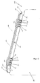
- FIG. 1 shows an embodiment of a radiation protection assembly 100 according to the present invention for attachment to a treatment table.
- the radiation protection arrangement 100 has a holder 110 which can be placed on a carrier rail of a treatment table (not shown). On the holder 110, a radiation protection curtain 160 is attached. Furthermore, the holder 110 has a fastening device 120. According to the in FIG. 1 As shown in the preferred embodiment of the present invention, the fastening device 120 has a first clamp part 121, a second clamp part 122, a third clamp part 123 and a fourth clamp part 124.
- the clamp members 121, 122, 123, 124 are attached to a long side of the holder 110, which in the mounted state in the direction of Treatment table shows.
- the clip parts 121, 122, 123, 124 each have an L-profile with a first leg L1, L1 ', L1 ", L1"' and a second leg L2, L2 ', L2 ", L2"' on.
- first legs L1, L1 'of the first clamp part 121 and the second clamp part 122 are aligned parallel to each other and the second legs L2, L2' of the first clamp part 121 and the second clamp part 122 face each other.
- the first bracket portion 121 is disposed at an upper edge of the holder 110 and the second bracket portion 122 is disposed at a lower edge of the holder 110.
- the first clamp part 121 is arranged with respect to a longitudinal direction of the holder 110 at a first distance d to the second clamp part 122, that the holder 110 in a first position in which the holder 110 is pivoted relative to the support rail at an angle with the carrier rail is brought into contact and can be brought by a pivoting movement in a second position in which the holder 110 is mounted on the support rail.
- the third clamp part 123 and the fourth clamp part 124 are arranged such that the first limbs L1 ", L1"'of the third and fourth clamp parts 123,124 are aligned parallel to each other and the second limbs L2 ", L2"' of the third and fourth clamp members 123, 124 in the same direction and the third and fourth clamp members 123, 124 are arranged such that the first legs L1 ", L1"'rest in the mounted state on the support rail.
- the distance n of the third clamp part 123 to the second clamp part 122 is 25 times larger than the 1st distance d between the first clamp part 121 and the second clamp part 122 in the present embodiment.
- the distance of the fourth clamp part 124 to the third clamp part 123 is in the present embodiment, the same as the first distance d between the first clamp part 121 and the second clamp part 122.
- the holder 110 has on its two short sides in each case a first part 140 of a hinge connection.
- the first part 140 of the articulated connection has a bore 141 and a pressing device 142.
- the first part 140 of the articulated connection is suitably connected to a second part 150 of the articulated connection, which is fastened, for example, to a holder of a second radiation protection arrangement, in such a way in that the first and second parts 140, 150 of the articulated connection form a screened articulated connection.
- the first part 140 has a bore 141 and a pressing device 142.
- the first and second parts 140, 150 of the hinge connection are described below in FIGS FIGS. 5 to 8 discussed in detail.
- the holder 110 has an additional rail 130, which is attached to the side facing away from the fastening device 120.
- the additional rail 130 is connected by corresponding bolts 131 with the holder 110, so that it is preferably objected to something of the holder 110.
- This complaint of the additional rail 130 of the holder 110 facilitates the possible placement of additional radiation shields, as in FIG. 9 shown.
- FIG. 2 shows a further embodiment of a radiation protection assembly 100 according to the present invention for attachment to a treatment table.
- the radiation protection arrangement 100 like those in FIG. 1 embodiment shown on a holder 110 which can be placed on a support rail of a treatment table.
- the embodiment shown differs from that in FIG. 1 shown embodiment in that the second leg L2 ", L2"'of the third and fourth clamp members 123, 124 as well as the second leg L2, L2' of the first clamp member 121 and the second clamp member 122 to each other.
- the radiation protection arrangement 100 or the holder 110 is pushed laterally onto the carrier rail, without the holder 110 being pivoted relative to the carrier rail of the treatment table.
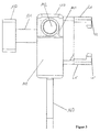
- FIG. 3 shows a side view according to a preferred embodiment of the present invention.
- the FIG. 3 embodiment shown here corresponds in its side view both in FIG. 1 embodiment shown as well as in FIG. 2 shown embodiment.
- the holder 110 has on its long side facing the treatment table the fastening device 120 with the first and the second clamp part 121, 122, wherein the two clamp parts 121, 122 each have an L-profile with the already discussed first and second legs L1, L1 ', L2, L2'.
- the first part 140 of the hinge connection On the front side or the short side of the holder 110 is the first part 140 of the hinge connection, the Bore 141 and the pressing device 142 has.
- the holder 110 On the long side facing away from the treatment table, the holder 110 has fastening bolts 131 to which the additional rail 130 is fastened. By the length of the bolt 131 while the additional rail 130 is spaced from the holder 110.
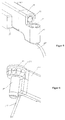
- FIG. 4 shows a perspective view of a radiation protection assembly 100 according to the present invention for attachment to a treatment table. This preferred embodiment is similar to the one in FIG. 2 shown embodiment. In particular, however, is in FIG. 4 again the additional rail 130 is shown completely.
- FIG. 5 shows an embodiment of the first part 140 of the hinge connection according to the present invention.
- the first part 140 of the hinge connection is fastened to the short side of the holder 110.
- the additional rail 130 and the protective curtain 160 are attached to the holder 110.
- the first part 140 of the articulated connection has the bore 141. According to the present embodiment is located in the bore a plain bearing bush made of plastic, preferably PTFE.
- FIG. 6 shows an embodiment of the second part 150 of the hinge connection according to the present invention.
- the second part 150 of the articulated connection can also be fastened to the short side of the holder 110.
- the second part 150 of the hinge connection can be attached to an additional radiation shield without holder 110, so that the additional radiation shield or the additional radiation protection arrangement is not directly in contact with the treatment table.
- the second part 150 of the articulated connection has a head 152 and a bolt 151.
- the head 152 has a plurality of recesses 154.
- the bolt 151 of the second part 150 of the articulated connection can be inserted into the bore 141 of the first part 140 of the articulated connection.
- the recesses 154 of the head 152 of the second part 150 of the articulated connection are designed such that the pressing device 142 is received by the recess 154 by inserting the bolt into the bore 141.
- the recesses 154 on the side facing the bolt 151 matching passages, so that when inserting the Bolzens 151 in the bore 141, the pressing device 142 can be easily absorbed by the recesses 154.
- the pin 151 at its end facing away from the head 152 on a chamfer, which facilitates the insertion of the pin 151 in the bore 141.
- FIG. 6 shows a further embodiment of the second part 150 of the hinge connection according to the present invention.
- an angle of 0.75 ° between the pin 151 and the main body of the second part 150 of the hinge connection is an angle of 0.75 °.
- the bolt 151 is not parallel to the main body of the second part 150 of the hinge connection.
- This angle preferably 0.75 °, provides a preload on the bolt. This bias ensures that when loaded the joint, for example, by a free-standing end on a part 140, 150 of the joint connection, the two connected by the joint connection radiation protection arrangements flush with each other.
- FIG. 8 shows a composite hinge connection of a first part 140 and a second part 150. It can be clearly seen that the pressing device 142 has been received by a recess 154, while the other recesses 154 of the head 152 are not occupied and the recesses 154 as a whole a grid form, so that by the rastered articulation predefined angle settings can be taken.
- the pressing device 142 By applying a predefined force, which is exerted on the first part 140, the pressing device 142 from a first detent position in which the pressing device 142 is located in a first recess 154, in a second detent position in which the pressing device 142 in a second Recess 154 is moved.
- a predefined force which is exerted on the first part 140
- the pressing device 142 By rotating the hinge connection against a predefined force, the pressing device 142 can be moved from a first to a second locking position.
- FIG. 9 shows a composite system of several radiation protection assemblies 100, 100 ', 100 ", which by the in the FIGS. 5 to 8 described joints are interconnected, according to an embodiment of the present invention.
- the radiation protection assemblies 100 ', 100 are connected to the radiation protection assembly 100 without being directly connected to the treatment table "pluggable radiation shields 170 which are attached to respective rails 130.
- the rasterized hinges make it possible to detect the positions of the radiation protection assemblies 100, 100 ', 100 "in an angle predefined by the recesses 154.
- the positions of the radiation protection assemblies 100, 100', 100" can be maintained with respect to each other in the tilt of the treatment table be as well as unintentional abutment of the radiation protection arrangements 100, 100 ', 100 ", for example, by the operating personnel.
- the invention also includes individual features in the figures, even though they are shown there in connection with other features and / or are not mentioned above or below. Also, the alternatives of embodiments and individual alternatives described in the figures and the description may be excluded from the subject matter of the invention or from the disclosed subject matter.
- the disclosure includes embodiments that include only the features described in the claims and in the embodiments, as well as those that include additional other features.
Landscapes
- Health & Medical Sciences (AREA)
- Engineering & Computer Science (AREA)
- Life Sciences & Earth Sciences (AREA)
- Physics & Mathematics (AREA)
- High Energy & Nuclear Physics (AREA)
- Medical Informatics (AREA)
- Biomedical Technology (AREA)
- Pathology (AREA)
- General Health & Medical Sciences (AREA)
- Public Health (AREA)
- Veterinary Medicine (AREA)
- Animal Behavior & Ethology (AREA)
- Radiology & Medical Imaging (AREA)
- Nuclear Medicine, Radiotherapy & Molecular Imaging (AREA)
- General Engineering & Computer Science (AREA)
- Biophysics (AREA)
- Optics & Photonics (AREA)
- Heart & Thoracic Surgery (AREA)
- Molecular Biology (AREA)
- Surgery (AREA)
- Accommodation For Nursing Or Treatment Tables (AREA)
- Radiation-Therapy Devices (AREA)
- Apparatus For Radiation Diagnosis (AREA)
- Curtains And Furnishings For Windows Or Doors (AREA)
Applications Claiming Priority (1)
| Application Number | Priority Date | Filing Date | Title |
|---|---|---|---|
| DE102015208829.4A DE102015208829B4 (de) | 2015-05-12 | 2015-05-12 | Strahlenschutzanordnung |
Publications (3)
| Publication Number | Publication Date |
|---|---|
| EP3100681A2 true EP3100681A2 (fr) | 2016-12-07 |
| EP3100681A3 EP3100681A3 (fr) | 2017-03-15 |
| EP3100681B1 EP3100681B1 (fr) | 2020-11-11 |
Family
ID=55970834
Family Applications (1)
| Application Number | Title | Priority Date | Filing Date |
|---|---|---|---|
| EP16168930.2A Active EP3100681B1 (fr) | 2015-05-12 | 2016-05-10 | Systeme de protection contre les rayonnements |
Country Status (4)
| Country | Link |
|---|---|
| US (1) | US9953731B2 (fr) |
| EP (1) | EP3100681B1 (fr) |
| CN (1) | CN106158059B (fr) |
| DE (1) | DE102015208829B4 (fr) |
Families Citing this family (8)
| Publication number | Priority date | Publication date | Assignee | Title |
|---|---|---|---|---|
| CN108324384A (zh) * | 2018-05-04 | 2018-07-27 | 傅丽秋 | 一种改良型医疗手术设备 |
| CN108324385A (zh) * | 2018-05-04 | 2018-07-27 | 吕丹丹 | 一种医疗手术设备 |
| CN108338845A (zh) * | 2018-05-04 | 2018-07-31 | 吕丹丹 | 一种先进的医疗手术设备 |
| DE102019003954A1 (de) | 2019-06-04 | 2020-12-10 | Mavig Gmbh | Verfahren zum Herstellen eines Strahlenschutzelements, Strahlenschutzelement und Strahlenschutzeinrichtung |
| US11786189B2 (en) * | 2021-11-21 | 2023-10-17 | Shimadzu Corporation | Proximity operation-type X-ray fluoroscopic imaging apparatus |
| CN114533107A (zh) * | 2022-03-22 | 2022-05-27 | 影诺高新科技(苏州)有限公司 | 一种便携式护帘 |
| CN114601491A (zh) * | 2022-03-22 | 2022-06-10 | 影诺高新科技(苏州)有限公司 | 一种便携式防护帘固定机构 |
| EP4542580A1 (fr) | 2023-10-20 | 2025-04-23 | MAVIG GmbH | Enveloppe en une pièce de matériaux de protection contre les rayonnements et son utilisation |
Citations (8)
| Publication number | Priority date | Publication date | Assignee | Title |
|---|---|---|---|---|
| DE1466848A1 (de) | 1964-03-14 | 1969-02-20 | Koch & Sterzel Kg | Sekundaerstrahlenschutzvorrichtung an Roentgenuntersuchungsgeraeten |
| DE1516420A1 (de) | 1966-03-19 | 1969-08-07 | Siemens Ag | Strahlenschutzvorrichtung fuer Roentgenuntersuchungsgeraete |
| DE2749826A1 (de) | 1976-11-10 | 1978-05-11 | Gen Electric | Roentgenstrahl-abschirmeinrichtung |
| DE3012463C2 (fr) | 1980-03-31 | 1989-06-22 | Siemens Ag, 1000 Berlin Und 8000 Muenchen, De | |
| DE29704613U1 (de) | 1996-03-26 | 1997-06-05 | Siemens AG, 80333 München | Strahlenschutzvorrichtung für ein Röntgendiagnostikgerät |
| WO2004107979A1 (fr) | 2003-06-05 | 2004-12-16 | Mavig Gmbh | Dispositif de protection anti-radiations comportant une enveloppe separable |
| DE102009025380A1 (de) | 2009-06-18 | 2010-12-23 | Mavig Gmbh | Strahlenschutzanordnung |
| DE102012218391A1 (de) | 2012-10-09 | 2014-04-10 | Mavig Gmbh | Strahlenschutzanordnung |
Family Cites Families (14)
| Publication number | Priority date | Publication date | Assignee | Title |
|---|---|---|---|---|
| DE2313201C2 (de) * | 1973-03-16 | 1982-06-24 | Siemens AG, 1000 Berlin und 8000 München | Strahlenschutzeinrichtung für ein Röntgenuntersuchungsgerät |
| US5006718A (en) * | 1989-07-21 | 1991-04-09 | Lenhart Mark J | X-ray shield for X-ray examination table |
| CN2500262Y (zh) * | 2001-09-14 | 2002-07-17 | 董蒲 | 组合式x射线防护屏 |
| US7511292B2 (en) * | 2004-10-28 | 2009-03-31 | Nfs-Radiation Protection Systems, Inc. | Radiation protection shield |
| US8716687B2 (en) * | 2008-03-31 | 2014-05-06 | Eco Cath-Lab Systems, Inc. | Method and apparatus for shielding medical personnel from radiation |
| GB2461569A (en) * | 2008-07-04 | 2010-01-06 | Kenex | Improved X-ray shield |
| DE102009053619B3 (de) * | 2009-11-17 | 2011-07-28 | MAVIG GmbH, 81829 | Strahlenschutz-Lamellenanordnung |
| DE102009057366B4 (de) * | 2009-12-08 | 2020-11-12 | Mavig Gmbh | Strahlenschutzvorrichtung |
| CN103417238A (zh) * | 2012-05-22 | 2013-12-04 | 莱芜钢铁集团有限公司医院 | 床边x光机用防护帘 |
| US20140048730A1 (en) * | 2012-08-15 | 2014-02-20 | Eco Cath-Lab Systems, Inc. | Radiation Protection System |
| CN203138530U (zh) * | 2013-02-22 | 2013-08-21 | 北京市华仁益康科技发展有限公司 | 可向上折起的医用x射线床边防护帘 |
| CA2908304A1 (fr) * | 2013-04-12 | 2014-10-16 | In & Tec S.R.L. | Charniere pour le mouvement de rotation regule d'une porte, en particulier d'une porte en verre |
| DE102013105374A1 (de) * | 2013-05-24 | 2014-11-27 | Aesculap Ag | Adaptiervorrichtung für einen OP-Tisch |
| CN203408059U (zh) * | 2013-08-08 | 2014-01-29 | 北京东方逸腾数码医疗设备技术有限公司 | 血管造影机床上一体化x射线防护装置 |
-
2015
- 2015-05-12 DE DE102015208829.4A patent/DE102015208829B4/de active Active
-
2016
- 2016-05-10 EP EP16168930.2A patent/EP3100681B1/fr active Active
- 2016-05-11 CN CN201610312539.XA patent/CN106158059B/zh active Active
- 2016-05-11 US US15/151,701 patent/US9953731B2/en active Active
Patent Citations (8)
| Publication number | Priority date | Publication date | Assignee | Title |
|---|---|---|---|---|
| DE1466848A1 (de) | 1964-03-14 | 1969-02-20 | Koch & Sterzel Kg | Sekundaerstrahlenschutzvorrichtung an Roentgenuntersuchungsgeraeten |
| DE1516420A1 (de) | 1966-03-19 | 1969-08-07 | Siemens Ag | Strahlenschutzvorrichtung fuer Roentgenuntersuchungsgeraete |
| DE2749826A1 (de) | 1976-11-10 | 1978-05-11 | Gen Electric | Roentgenstrahl-abschirmeinrichtung |
| DE3012463C2 (fr) | 1980-03-31 | 1989-06-22 | Siemens Ag, 1000 Berlin Und 8000 Muenchen, De | |
| DE29704613U1 (de) | 1996-03-26 | 1997-06-05 | Siemens AG, 80333 München | Strahlenschutzvorrichtung für ein Röntgendiagnostikgerät |
| WO2004107979A1 (fr) | 2003-06-05 | 2004-12-16 | Mavig Gmbh | Dispositif de protection anti-radiations comportant une enveloppe separable |
| DE102009025380A1 (de) | 2009-06-18 | 2010-12-23 | Mavig Gmbh | Strahlenschutzanordnung |
| DE102012218391A1 (de) | 2012-10-09 | 2014-04-10 | Mavig Gmbh | Strahlenschutzanordnung |
Also Published As
| Publication number | Publication date |
|---|---|
| EP3100681A3 (fr) | 2017-03-15 |
| DE102015208829B4 (de) | 2020-08-27 |
| CN106158059A (zh) | 2016-11-23 |
| US9953731B2 (en) | 2018-04-24 |
| CN106158059B (zh) | 2018-07-06 |
| DE102015208829A1 (de) | 2016-11-17 |
| EP3100681B1 (fr) | 2020-11-11 |
| US20160336085A1 (en) | 2016-11-17 |
Similar Documents
| Publication | Publication Date | Title |
|---|---|---|
| DE102015208829B4 (de) | Strahlenschutzanordnung | |
| EP2906122B1 (fr) | Ensemble de protection contre les radiations | |
| EP3308680A2 (fr) | Adaptateur de couplage à une glissière pour rideaux | |
| DE202010012567U1 (de) | Seilumlenkstück für einen Seilfensterheber | |
| WO2012100794A1 (fr) | Pince de blocage à verrouillage | |
| DE102012211438B4 (de) | Befestigungseinrichtung zum Befestigen von Zubehörteilen an medizinischen Einrichtungen | |
| DE102009025380A1 (de) | Strahlenschutzanordnung | |
| DE8903958U1 (de) | Vorrichtung zum Führen und Halten von Leiterplatten | |
| DE102006048107B4 (de) | Vorrichtung zum Sperren einer Schwenkrichtung eines gegenüber einem Halteelement verschwenkbaren Bauteils | |
| DE202010007139U1 (de) | Vorrichtung zur Befestigung eines Moduls zur Nutzung von Sonnenenergie | |
| DE102019200066A1 (de) | Lukenanordnung für ein Freizeitfahrzeug | |
| EP2594165B1 (fr) | Support pour la fixation par serrage d'un objet, notamment d'un dispositif de tensionnement d'un cable pour un dispositif de pare-soleil et/ou de protection contre la vue, sur un cadre de fenêtre ou de porte | |
| WO2021013304A1 (fr) | Dispositif à coussinets sphériques pour une articulation | |
| DE202010005777U1 (de) | Schnellmontage-Scharnier | |
| DE202010013558U1 (de) | Scharnier für ein Insekten- und/oder Pollenschutzgitter | |
| DE10050279A1 (de) | Flexfolienverlegehilfe | |
| DE102010027957A1 (de) | Eckband einer Ecklageranordnung | |
| DE102015118903A1 (de) | Kabelführungselement | |
| DE102013203352B4 (de) | Orthese | |
| DE202009004833U1 (de) | Rastelement | |
| DE102009051594A1 (de) | Haken, insbesondere für Sicherheitseinrichtungen | |
| DE202025100353U1 (de) | Türhakenanordnung | |
| DE102005042717A1 (de) | Gleiter zur Anordnung eines Vorhangs an einer Vorhangschiene, Vorhangschiene und Gardinenhaltevorrichtung | |
| DE102017204616A1 (de) | Vorrichtung zur Befestigung an einem Bauteil | |
| LU101158B1 (de) | Verbindungselement mit zwei unabhängigen Haltevorrichtungen |
Legal Events
| Date | Code | Title | Description |
|---|---|---|---|
| PUAI | Public reference made under article 153(3) epc to a published international application that has entered the european phase |
Free format text: ORIGINAL CODE: 0009012 |
|
| STAA | Information on the status of an ep patent application or granted ep patent |
Free format text: STATUS: THE APPLICATION HAS BEEN PUBLISHED |
|
| AK | Designated contracting states |
Kind code of ref document: A2 Designated state(s): AL AT BE BG CH CY CZ DE DK EE ES FI FR GB GR HR HU IE IS IT LI LT LU LV MC MK MT NL NO PL PT RO RS SE SI SK SM TR |
|
| AX | Request for extension of the european patent |
Extension state: BA ME |
|
| RIN1 | Information on inventor provided before grant (corrected) |
Inventor name: BUCHMEYER, MARKUS |
|
| PUAL | Search report despatched |
Free format text: ORIGINAL CODE: 0009013 |
|
| AK | Designated contracting states |
Kind code of ref document: A3 Designated state(s): AL AT BE BG CH CY CZ DE DK EE ES FI FR GB GR HR HU IE IS IT LI LT LU LV MC MK MT NL NO PL PT RO RS SE SI SK SM TR |
|
| AX | Request for extension of the european patent |
Extension state: BA ME |
|
| RIC1 | Information provided on ipc code assigned before grant |
Ipc: A61B 6/10 20060101AFI20170206BHEP |
|
| STAA | Information on the status of an ep patent application or granted ep patent |
Free format text: STATUS: REQUEST FOR EXAMINATION WAS MADE |
|
| 17P | Request for examination filed |
Effective date: 20170905 |
|
| RBV | Designated contracting states (corrected) |
Designated state(s): AL AT BE BG CH CY CZ DE DK EE ES FI FR GB GR HR HU IE IS IT LI LT LU LV MC MK MT NL NO PL PT RO RS SE SI SK SM TR |
|
| GRAP | Despatch of communication of intention to grant a patent |
Free format text: ORIGINAL CODE: EPIDOSNIGR1 |
|
| STAA | Information on the status of an ep patent application or granted ep patent |
Free format text: STATUS: GRANT OF PATENT IS INTENDED |
|
| INTG | Intention to grant announced |
Effective date: 20200406 |
|
| RIN1 | Information on inventor provided before grant (corrected) |
Inventor name: BUCHMEYER, MARKUS |
|
| GRAJ | Information related to disapproval of communication of intention to grant by the applicant or resumption of examination proceedings by the epo deleted |
Free format text: ORIGINAL CODE: EPIDOSDIGR1 |
|
| STAA | Information on the status of an ep patent application or granted ep patent |
Free format text: STATUS: REQUEST FOR EXAMINATION WAS MADE |
|
| INTC | Intention to grant announced (deleted) | ||
| GRAR | Information related to intention to grant a patent recorded |
Free format text: ORIGINAL CODE: EPIDOSNIGR71 |
|
| GRAS | Grant fee paid |
Free format text: ORIGINAL CODE: EPIDOSNIGR3 |
|
| STAA | Information on the status of an ep patent application or granted ep patent |
Free format text: STATUS: GRANT OF PATENT IS INTENDED |
|
| GRAA | (expected) grant |
Free format text: ORIGINAL CODE: 0009210 |
|
| STAA | Information on the status of an ep patent application or granted ep patent |
Free format text: STATUS: THE PATENT HAS BEEN GRANTED |
|
| AK | Designated contracting states |
Kind code of ref document: B1 Designated state(s): AL AT BE BG CH CY CZ DE DK EE ES FI FR GB GR HR HU IE IS IT LI LT LU LV MC MK MT NL NO PL PT RO RS SE SI SK SM TR |
|
| INTG | Intention to grant announced |
Effective date: 20201006 |
|
| REG | Reference to a national code |
Ref country code: GB Ref legal event code: FG4D Free format text: NOT ENGLISH |
|
| REG | Reference to a national code |
Ref country code: CH Ref legal event code: EP |
|
| REG | Reference to a national code |
Ref country code: AT Ref legal event code: REF Ref document number: 1332692 Country of ref document: AT Kind code of ref document: T Effective date: 20201115 |
|
| REG | Reference to a national code |
Ref country code: DE Ref legal event code: R096 Ref document number: 502016011650 Country of ref document: DE |
|
| REG | Reference to a national code |
Ref country code: IE Ref legal event code: FG4D Free format text: LANGUAGE OF EP DOCUMENT: GERMAN |
|
| REG | Reference to a national code |
Ref country code: NL Ref legal event code: FP |
|
| PG25 | Lapsed in a contracting state [announced via postgrant information from national office to epo] |
Ref country code: NO Free format text: LAPSE BECAUSE OF FAILURE TO SUBMIT A TRANSLATION OF THE DESCRIPTION OR TO PAY THE FEE WITHIN THE PRESCRIBED TIME-LIMIT Effective date: 20210211 Ref country code: PT Free format text: LAPSE BECAUSE OF FAILURE TO SUBMIT A TRANSLATION OF THE DESCRIPTION OR TO PAY THE FEE WITHIN THE PRESCRIBED TIME-LIMIT Effective date: 20210311 Ref country code: RS Free format text: LAPSE BECAUSE OF FAILURE TO SUBMIT A TRANSLATION OF THE DESCRIPTION OR TO PAY THE FEE WITHIN THE PRESCRIBED TIME-LIMIT Effective date: 20201111 Ref country code: FI Free format text: LAPSE BECAUSE OF FAILURE TO SUBMIT A TRANSLATION OF THE DESCRIPTION OR TO PAY THE FEE WITHIN THE PRESCRIBED TIME-LIMIT Effective date: 20201111 Ref country code: GR Free format text: LAPSE BECAUSE OF FAILURE TO SUBMIT A TRANSLATION OF THE DESCRIPTION OR TO PAY THE FEE WITHIN THE PRESCRIBED TIME-LIMIT Effective date: 20210212 |
|
| PG25 | Lapsed in a contracting state [announced via postgrant information from national office to epo] |
Ref country code: BG Free format text: LAPSE BECAUSE OF FAILURE TO SUBMIT A TRANSLATION OF THE DESCRIPTION OR TO PAY THE FEE WITHIN THE PRESCRIBED TIME-LIMIT Effective date: 20210211 Ref country code: SE Free format text: LAPSE BECAUSE OF FAILURE TO SUBMIT A TRANSLATION OF THE DESCRIPTION OR TO PAY THE FEE WITHIN THE PRESCRIBED TIME-LIMIT Effective date: 20201111 Ref country code: LV Free format text: LAPSE BECAUSE OF FAILURE TO SUBMIT A TRANSLATION OF THE DESCRIPTION OR TO PAY THE FEE WITHIN THE PRESCRIBED TIME-LIMIT Effective date: 20201111 Ref country code: IS Free format text: LAPSE BECAUSE OF FAILURE TO SUBMIT A TRANSLATION OF THE DESCRIPTION OR TO PAY THE FEE WITHIN THE PRESCRIBED TIME-LIMIT Effective date: 20210311 Ref country code: PL Free format text: LAPSE BECAUSE OF FAILURE TO SUBMIT A TRANSLATION OF THE DESCRIPTION OR TO PAY THE FEE WITHIN THE PRESCRIBED TIME-LIMIT Effective date: 20201111 |
|
| REG | Reference to a national code |
Ref country code: LT Ref legal event code: MG9D |
|
| PG25 | Lapsed in a contracting state [announced via postgrant information from national office to epo] |
Ref country code: HR Free format text: LAPSE BECAUSE OF FAILURE TO SUBMIT A TRANSLATION OF THE DESCRIPTION OR TO PAY THE FEE WITHIN THE PRESCRIBED TIME-LIMIT Effective date: 20201111 |
|
| PG25 | Lapsed in a contracting state [announced via postgrant information from national office to epo] |
Ref country code: SK Free format text: LAPSE BECAUSE OF FAILURE TO SUBMIT A TRANSLATION OF THE DESCRIPTION OR TO PAY THE FEE WITHIN THE PRESCRIBED TIME-LIMIT Effective date: 20201111 Ref country code: RO Free format text: LAPSE BECAUSE OF FAILURE TO SUBMIT A TRANSLATION OF THE DESCRIPTION OR TO PAY THE FEE WITHIN THE PRESCRIBED TIME-LIMIT Effective date: 20201111 Ref country code: EE Free format text: LAPSE BECAUSE OF FAILURE TO SUBMIT A TRANSLATION OF THE DESCRIPTION OR TO PAY THE FEE WITHIN THE PRESCRIBED TIME-LIMIT Effective date: 20201111 Ref country code: CZ Free format text: LAPSE BECAUSE OF FAILURE TO SUBMIT A TRANSLATION OF THE DESCRIPTION OR TO PAY THE FEE WITHIN THE PRESCRIBED TIME-LIMIT Effective date: 20201111 Ref country code: SM Free format text: LAPSE BECAUSE OF FAILURE TO SUBMIT A TRANSLATION OF THE DESCRIPTION OR TO PAY THE FEE WITHIN THE PRESCRIBED TIME-LIMIT Effective date: 20201111 Ref country code: LT Free format text: LAPSE BECAUSE OF FAILURE TO SUBMIT A TRANSLATION OF THE DESCRIPTION OR TO PAY THE FEE WITHIN THE PRESCRIBED TIME-LIMIT Effective date: 20201111 |
|
| REG | Reference to a national code |
Ref country code: DE Ref legal event code: R097 Ref document number: 502016011650 Country of ref document: DE |
|
| PG25 | Lapsed in a contracting state [announced via postgrant information from national office to epo] |
Ref country code: DK Free format text: LAPSE BECAUSE OF FAILURE TO SUBMIT A TRANSLATION OF THE DESCRIPTION OR TO PAY THE FEE WITHIN THE PRESCRIBED TIME-LIMIT Effective date: 20201111 |
|
| PLBE | No opposition filed within time limit |
Free format text: ORIGINAL CODE: 0009261 |
|
| STAA | Information on the status of an ep patent application or granted ep patent |
Free format text: STATUS: NO OPPOSITION FILED WITHIN TIME LIMIT |
|
| 26N | No opposition filed |
Effective date: 20210812 |
|
| PG25 | Lapsed in a contracting state [announced via postgrant information from national office to epo] |
Ref country code: IT Free format text: LAPSE BECAUSE OF FAILURE TO SUBMIT A TRANSLATION OF THE DESCRIPTION OR TO PAY THE FEE WITHIN THE PRESCRIBED TIME-LIMIT Effective date: 20201111 Ref country code: AL Free format text: LAPSE BECAUSE OF FAILURE TO SUBMIT A TRANSLATION OF THE DESCRIPTION OR TO PAY THE FEE WITHIN THE PRESCRIBED TIME-LIMIT Effective date: 20201111 |
|
| PG25 | Lapsed in a contracting state [announced via postgrant information from national office to epo] |
Ref country code: ES Free format text: LAPSE BECAUSE OF FAILURE TO SUBMIT A TRANSLATION OF THE DESCRIPTION OR TO PAY THE FEE WITHIN THE PRESCRIBED TIME-LIMIT Effective date: 20201111 Ref country code: SI Free format text: LAPSE BECAUSE OF FAILURE TO SUBMIT A TRANSLATION OF THE DESCRIPTION OR TO PAY THE FEE WITHIN THE PRESCRIBED TIME-LIMIT Effective date: 20201111 |
|
| REG | Reference to a national code |
Ref country code: CH Ref legal event code: PL |
|
| PG25 | Lapsed in a contracting state [announced via postgrant information from national office to epo] |
Ref country code: LU Free format text: LAPSE BECAUSE OF NON-PAYMENT OF DUE FEES Effective date: 20210510 Ref country code: MC Free format text: LAPSE BECAUSE OF FAILURE TO SUBMIT A TRANSLATION OF THE DESCRIPTION OR TO PAY THE FEE WITHIN THE PRESCRIBED TIME-LIMIT Effective date: 20201111 Ref country code: LI Free format text: LAPSE BECAUSE OF NON-PAYMENT OF DUE FEES Effective date: 20210531 Ref country code: CH Free format text: LAPSE BECAUSE OF NON-PAYMENT OF DUE FEES Effective date: 20210531 |
|
| REG | Reference to a national code |
Ref country code: BE Ref legal event code: MM Effective date: 20210531 |
|
| PG25 | Lapsed in a contracting state [announced via postgrant information from national office to epo] |
Ref country code: IE Free format text: LAPSE BECAUSE OF NON-PAYMENT OF DUE FEES Effective date: 20210510 |
|
| PG25 | Lapsed in a contracting state [announced via postgrant information from national office to epo] |
Ref country code: IS Free format text: LAPSE BECAUSE OF FAILURE TO SUBMIT A TRANSLATION OF THE DESCRIPTION OR TO PAY THE FEE WITHIN THE PRESCRIBED TIME-LIMIT Effective date: 20210311 |
|
| REG | Reference to a national code |
Ref country code: AT Ref legal event code: MM01 Ref document number: 1332692 Country of ref document: AT Kind code of ref document: T Effective date: 20210510 |
|
| PG25 | Lapsed in a contracting state [announced via postgrant information from national office to epo] |
Ref country code: BE Free format text: LAPSE BECAUSE OF NON-PAYMENT OF DUE FEES Effective date: 20210531 |
|
| PG25 | Lapsed in a contracting state [announced via postgrant information from national office to epo] |
Ref country code: AT Free format text: LAPSE BECAUSE OF NON-PAYMENT OF DUE FEES Effective date: 20210510 |
|
| PG25 | Lapsed in a contracting state [announced via postgrant information from national office to epo] |
Ref country code: HU Free format text: LAPSE BECAUSE OF FAILURE TO SUBMIT A TRANSLATION OF THE DESCRIPTION OR TO PAY THE FEE WITHIN THE PRESCRIBED TIME-LIMIT; INVALID AB INITIO Effective date: 20160510 |
|
| PG25 | Lapsed in a contracting state [announced via postgrant information from national office to epo] |
Ref country code: CY Free format text: LAPSE BECAUSE OF FAILURE TO SUBMIT A TRANSLATION OF THE DESCRIPTION OR TO PAY THE FEE WITHIN THE PRESCRIBED TIME-LIMIT Effective date: 20201111 |
|
| PG25 | Lapsed in a contracting state [announced via postgrant information from national office to epo] |
Ref country code: MK Free format text: LAPSE BECAUSE OF FAILURE TO SUBMIT A TRANSLATION OF THE DESCRIPTION OR TO PAY THE FEE WITHIN THE PRESCRIBED TIME-LIMIT Effective date: 20201111 |
|
| PG25 | Lapsed in a contracting state [announced via postgrant information from national office to epo] |
Ref country code: MT Free format text: LAPSE BECAUSE OF FAILURE TO SUBMIT A TRANSLATION OF THE DESCRIPTION OR TO PAY THE FEE WITHIN THE PRESCRIBED TIME-LIMIT Effective date: 20201111 |
|
| PGFP | Annual fee paid to national office [announced via postgrant information from national office to epo] |
Ref country code: NL Payment date: 20250526 Year of fee payment: 10 |
|
| PGFP | Annual fee paid to national office [announced via postgrant information from national office to epo] |
Ref country code: DE Payment date: 20250530 Year of fee payment: 10 |
|
| PGFP | Annual fee paid to national office [announced via postgrant information from national office to epo] |
Ref country code: GB Payment date: 20250528 Year of fee payment: 10 |
|
| PGFP | Annual fee paid to national office [announced via postgrant information from national office to epo] |
Ref country code: FR Payment date: 20250527 Year of fee payment: 10 |
|
| PG25 | Lapsed in a contracting state [announced via postgrant information from national office to epo] |
Ref country code: TR Free format text: LAPSE BECAUSE OF FAILURE TO SUBMIT A TRANSLATION OF THE DESCRIPTION OR TO PAY THE FEE WITHIN THE PRESCRIBED TIME-LIMIT Effective date: 20201111 |