EP3100686A1 - Medizinische vorrichtung und medizinisches system - Google Patents
Medizinische vorrichtung und medizinisches system Download PDFInfo
- Publication number
- EP3100686A1 EP3100686A1 EP15742852.5A EP15742852A EP3100686A1 EP 3100686 A1 EP3100686 A1 EP 3100686A1 EP 15742852 A EP15742852 A EP 15742852A EP 3100686 A1 EP3100686 A1 EP 3100686A1
- Authority
- EP
- European Patent Office
- Prior art keywords
- manipulator
- endoscope
- sheath
- treatment tool
- medical apparatus
- Prior art date
- Legal status (The legal status is an assumption and is not a legal conclusion. Google has not performed a legal analysis and makes no representation as to the accuracy of the status listed.)
- Withdrawn
Links
- 238000011282 treatment Methods 0.000 claims abstract description 184
- 239000012636 effector Substances 0.000 claims description 63
- 230000002123 temporal effect Effects 0.000 claims description 18
- 238000005452 bending Methods 0.000 description 9
- 239000012530 fluid Substances 0.000 description 8
- 230000008961 swelling Effects 0.000 description 8
- 238000003780 insertion Methods 0.000 description 5
- 230000037431 insertion Effects 0.000 description 5
- 238000002347 injection Methods 0.000 description 3
- 239000007924 injection Substances 0.000 description 3
- 238000002357 laparoscopic surgery Methods 0.000 description 2
- 239000000463 material Substances 0.000 description 2
- 210000001015 abdomen Anatomy 0.000 description 1
- 230000005540 biological transmission Effects 0.000 description 1
- 230000003247 decreasing effect Effects 0.000 description 1
- 238000001514 detection method Methods 0.000 description 1
- 230000000694 effects Effects 0.000 description 1
- 239000002783 friction material Substances 0.000 description 1
- 238000010348 incorporation Methods 0.000 description 1
- 210000002429 large intestine Anatomy 0.000 description 1
- 238000012986 modification Methods 0.000 description 1
- 230000004048 modification Effects 0.000 description 1
- 210000000056 organ Anatomy 0.000 description 1
- 230000002265 prevention Effects 0.000 description 1
- 238000000926 separation method Methods 0.000 description 1
- 239000000243 solution Substances 0.000 description 1
- 238000001356 surgical procedure Methods 0.000 description 1
Images








Classifications
-
- A—HUMAN NECESSITIES
- A61—MEDICAL OR VETERINARY SCIENCE; HYGIENE
- A61B—DIAGNOSIS; SURGERY; IDENTIFICATION
- A61B1/00—Instruments for performing medical examinations of the interior of cavities or tubes of the body by visual or photographical inspection, e.g. endoscopes; Illuminating arrangements therefor
- A61B1/00131—Accessories for endoscopes
- A61B1/0014—Fastening element for attaching accessories to the outside of an endoscope, e.g. clips, clamps or bands
-
- A—HUMAN NECESSITIES
- A61—MEDICAL OR VETERINARY SCIENCE; HYGIENE
- A61B—DIAGNOSIS; SURGERY; IDENTIFICATION
- A61B1/00—Instruments for performing medical examinations of the interior of cavities or tubes of the body by visual or photographical inspection, e.g. endoscopes; Illuminating arrangements therefor
- A61B1/00002—Operational features of endoscopes
- A61B1/00004—Operational features of endoscopes characterised by electronic signal processing
- A61B1/00006—Operational features of endoscopes characterised by electronic signal processing of control signals
-
- A—HUMAN NECESSITIES
- A61—MEDICAL OR VETERINARY SCIENCE; HYGIENE
- A61B—DIAGNOSIS; SURGERY; IDENTIFICATION
- A61B1/00—Instruments for performing medical examinations of the interior of cavities or tubes of the body by visual or photographical inspection, e.g. endoscopes; Illuminating arrangements therefor
- A61B1/00002—Operational features of endoscopes
- A61B1/00004—Operational features of endoscopes characterised by electronic signal processing
- A61B1/00009—Operational features of endoscopes characterised by electronic signal processing of image signals during a use of endoscope
-
- A—HUMAN NECESSITIES
- A61—MEDICAL OR VETERINARY SCIENCE; HYGIENE
- A61B—DIAGNOSIS; SURGERY; IDENTIFICATION
- A61B1/00—Instruments for performing medical examinations of the interior of cavities or tubes of the body by visual or photographical inspection, e.g. endoscopes; Illuminating arrangements therefor
- A61B1/00002—Operational features of endoscopes
- A61B1/00043—Operational features of endoscopes provided with output arrangements
- A61B1/00045—Display arrangement
-
- A—HUMAN NECESSITIES
- A61—MEDICAL OR VETERINARY SCIENCE; HYGIENE
- A61B—DIAGNOSIS; SURGERY; IDENTIFICATION
- A61B1/00—Instruments for performing medical examinations of the interior of cavities or tubes of the body by visual or photographical inspection, e.g. endoscopes; Illuminating arrangements therefor
- A61B1/00131—Accessories for endoscopes
- A61B1/00135—Oversleeves mounted on the endoscope prior to insertion
-
- A—HUMAN NECESSITIES
- A61—MEDICAL OR VETERINARY SCIENCE; HYGIENE
- A61B—DIAGNOSIS; SURGERY; IDENTIFICATION
- A61B1/00—Instruments for performing medical examinations of the interior of cavities or tubes of the body by visual or photographical inspection, e.g. endoscopes; Illuminating arrangements therefor
- A61B1/012—Instruments for performing medical examinations of the interior of cavities or tubes of the body by visual or photographical inspection, e.g. endoscopes; Illuminating arrangements therefor characterised by internal passages or accessories therefor
- A61B1/018—Instruments for performing medical examinations of the interior of cavities or tubes of the body by visual or photographical inspection, e.g. endoscopes; Illuminating arrangements therefor characterised by internal passages or accessories therefor for receiving instruments
-
- A—HUMAN NECESSITIES
- A61—MEDICAL OR VETERINARY SCIENCE; HYGIENE
- A61B—DIAGNOSIS; SURGERY; IDENTIFICATION
- A61B18/00—Surgical instruments, devices or methods for transferring non-mechanical forms of energy to or from the body
- A61B18/04—Surgical instruments, devices or methods for transferring non-mechanical forms of energy to or from the body by heating
- A61B18/12—Surgical instruments, devices or methods for transferring non-mechanical forms of energy to or from the body by heating by passing a current through the tissue to be heated, e.g. high-frequency current
- A61B18/14—Probes or electrodes therefor
- A61B18/1492—Probes or electrodes therefor having a flexible, catheter-like structure, e.g. for heart ablation
-
- A—HUMAN NECESSITIES
- A61—MEDICAL OR VETERINARY SCIENCE; HYGIENE
- A61B—DIAGNOSIS; SURGERY; IDENTIFICATION
- A61B34/00—Computer-aided surgery; Manipulators or robots specially adapted for use in surgery
- A61B34/70—Manipulators specially adapted for use in surgery
-
- A—HUMAN NECESSITIES
- A61—MEDICAL OR VETERINARY SCIENCE; HYGIENE
- A61B—DIAGNOSIS; SURGERY; IDENTIFICATION
- A61B90/00—Instruments, implements or accessories specially adapted for surgery or diagnosis and not covered by any of the groups A61B1/00 - A61B50/00, e.g. for luxation treatment or for protecting wound edges
- A61B90/03—Automatic limiting or abutting means, e.g. for safety
-
- A—HUMAN NECESSITIES
- A61—MEDICAL OR VETERINARY SCIENCE; HYGIENE
- A61B—DIAGNOSIS; SURGERY; IDENTIFICATION
- A61B90/00—Instruments, implements or accessories specially adapted for surgery or diagnosis and not covered by any of the groups A61B1/00 - A61B50/00, e.g. for luxation treatment or for protecting wound edges
- A61B90/50—Supports for surgical instruments, e.g. articulated arms
- A61B90/57—Accessory clamps
-
- A—HUMAN NECESSITIES
- A61—MEDICAL OR VETERINARY SCIENCE; HYGIENE
- A61B—DIAGNOSIS; SURGERY; IDENTIFICATION
- A61B17/00—Surgical instruments, devices or methods
- A61B17/34—Trocars; Puncturing needles
- A61B17/3478—Endoscopic needles, e.g. for infusion
-
- A—HUMAN NECESSITIES
- A61—MEDICAL OR VETERINARY SCIENCE; HYGIENE
- A61B—DIAGNOSIS; SURGERY; IDENTIFICATION
- A61B17/00—Surgical instruments, devices or methods
- A61B17/00234—Surgical instruments, devices or methods for minimally invasive surgery
- A61B2017/00292—Surgical instruments, devices or methods for minimally invasive surgery mounted on or guided by flexible, e.g. catheter-like, means
-
- A—HUMAN NECESSITIES
- A61—MEDICAL OR VETERINARY SCIENCE; HYGIENE
- A61B—DIAGNOSIS; SURGERY; IDENTIFICATION
- A61B17/00—Surgical instruments, devices or methods
- A61B17/00234—Surgical instruments, devices or methods for minimally invasive surgery
- A61B2017/00292—Surgical instruments, devices or methods for minimally invasive surgery mounted on or guided by flexible, e.g. catheter-like, means
- A61B2017/003—Steerable
- A61B2017/00305—Constructional details of the flexible means
- A61B2017/00314—Separate linked members
-
- A—HUMAN NECESSITIES
- A61—MEDICAL OR VETERINARY SCIENCE; HYGIENE
- A61B—DIAGNOSIS; SURGERY; IDENTIFICATION
- A61B17/00—Surgical instruments, devices or methods
- A61B17/00234—Surgical instruments, devices or methods for minimally invasive surgery
- A61B2017/00292—Surgical instruments, devices or methods for minimally invasive surgery mounted on or guided by flexible, e.g. catheter-like, means
- A61B2017/0034—Surgical instruments, devices or methods for minimally invasive surgery mounted on or guided by flexible, e.g. catheter-like, means adapted to be inserted through a working channel of an endoscope
-
- A—HUMAN NECESSITIES
- A61—MEDICAL OR VETERINARY SCIENCE; HYGIENE
- A61B—DIAGNOSIS; SURGERY; IDENTIFICATION
- A61B17/00—Surgical instruments, devices or methods
- A61B2017/00477—Coupling
-
- A—HUMAN NECESSITIES
- A61—MEDICAL OR VETERINARY SCIENCE; HYGIENE
- A61B—DIAGNOSIS; SURGERY; IDENTIFICATION
- A61B17/00—Surgical instruments, devices or methods
- A61B2017/00535—Surgical instruments, devices or methods pneumatically or hydraulically operated
- A61B2017/00557—Surgical instruments, devices or methods pneumatically or hydraulically operated inflatable
-
- A—HUMAN NECESSITIES
- A61—MEDICAL OR VETERINARY SCIENCE; HYGIENE
- A61B—DIAGNOSIS; SURGERY; IDENTIFICATION
- A61B17/00—Surgical instruments, devices or methods
- A61B2017/00831—Material properties
- A61B2017/00876—Material properties magnetic
-
- A—HUMAN NECESSITIES
- A61—MEDICAL OR VETERINARY SCIENCE; HYGIENE
- A61B—DIAGNOSIS; SURGERY; IDENTIFICATION
- A61B17/00—Surgical instruments, devices or methods
- A61B17/28—Surgical forceps
- A61B17/29—Forceps for use in minimally invasive surgery
- A61B2017/2901—Details of shaft
- A61B2017/2908—Multiple segments connected by articulations
-
- A—HUMAN NECESSITIES
- A61—MEDICAL OR VETERINARY SCIENCE; HYGIENE
- A61B—DIAGNOSIS; SURGERY; IDENTIFICATION
- A61B34/00—Computer-aided surgery; Manipulators or robots specially adapted for use in surgery
- A61B34/30—Surgical robots
- A61B2034/301—Surgical robots for introducing or steering flexible instruments inserted into the body, e.g. catheters or endoscopes
Definitions
- the present invention relates generally to a medical apparatus and a medical system including a treatment tool inserted in a patient's body for viewing and treating an affected site.
- Patent Publication 1 discloses how to attach a treatment tool to an endoscope using an external tube in such a way as not to reduce the flexibility of a flexible portion.
- Patent Publication 1 JP(A) 5-307143
- One embodiment according to the invention has been contrived with the abovementioned object(s) in mind, and provides a medical apparatus and a medical system improved in terms of operability.
- a medical apparatus characterized by including:
- the medical apparatus further includes an endoscope/manipulator control unit for independent control of the endoscope and the manipulator, wherein:
- the medical apparatus further includes:
- the first or second connector member connects together the manipulator and the sheath such that they are relatively movable.
- the medical apparatus further includes a movement restrictor for stopping movement of the first or second connector members in a given position for movement restriction.
- the medical apparatus further includes a fixation mechanism for temporal fixation in a given position of the treatment tool which can move forward and backward into from the sheath.
- the manipulator further includes an end effector for implementing medical treatments.
- the treatment tool and the end effector are independently operable.
- the treatment tool is capable of fixing the manipulator temporarily in place
- the manipulator is capable of fixing the treatment tool temporarily in place
- a medical system characterized by including:
- Fig. 1 is illustrative in schematic of one example of the medical apparatus 1 according to the first embodiment of the invention.
- an endoscope 2 and a manipulator 3 are inserted through a common tubular member 10 having flexibility.
- the medical apparatus 1 according to the first embodiment includes the endoscope 2, the manipulator 3 having at least one degree of freedom, a flexible cylindrical sheath 4 mounted on the outer circumference of the manipulator 3, a treatment tool 5 inserted through the sheath 4, an endoscope/manipulator operating unit 11 for independent operation of the endoscope 2 and manipulator 3, and an endoscope/ manipulator control unit 16 for controlling the endoscope 2 and manipulator 3 independently in association with operation of the endoscope/manipulator operating unit 11.
- the treatment tool 5 can more easily be placed within the field of view of the endoscope 2 by mounting the sheath 4 having the treatment tool 5 inserted through it on the manipulator 3 and operating the endoscope 2 or manipulator 3, thereby improving on operability.
- the endoscope/manipulator operating unit 11 formed in an integral form, operates the endoscope 2 and manipulator 3 independently, and the endoscope/manipulator control unit 16, formed in an integral form, controls the endoscope 2 and manipulator 3 independently.
- the medical apparatus 1 is well compatible with treatment implemented by independent operation of the endoscope 2 and manipulator 3, resulting in an improved operability.
- Fig. 2 is illustrative in schematic of one embodiment of the medical apparatus 1 according to the second embodiment of the invention.
- an endoscope operating unit 12 for operation of the endoscope 2 and a manipulator operating unit 13 for operation of the manipulator 3 are used in place of the endoscope/manipulator operating unit 11 in the medical apparatus 1 according to the first embodiment of the invention: they are provided separately and operated independently.
- an endoscope/manipulator control unit 16 is integrally formed to control the endoscope 2 and manipulator 3 independently.
- the medical apparatus 1 according to the second embodiment of the invention is well compatible with treatment implemented by independent operation of the endoscope 2 and manipulator 3, resulting in a more improved operability.
- Fig. 3 is illustrative in schematic of one example of the medical apparatus 1 according to the third embodiment of the invention.
- an endoscope operating unit 12 for operation of the endoscope 2 and a manipulator operating unit 13 for operation of the manipulator 3 are used in place of the endoscope/manipulator operating unit 11 in the medical apparatus 1 according to the first embodiment of the invention: they are provided separately and operated independently.
- an endoscope control unit 17 and a manipulator control unit 18 are used in place of the endoscope/manipulator control unit 16 in the medical apparatus 1 according to the first embodiment of the invention are separately provided for independent control of the endoscope 2 and manipulator 3.
- the medical apparatus 1 according to the third embodiment of the invention is well compatible with treatment implemented by independent operation of the endoscope 2 and manipulator 3, resulting in an improved operability.
- Fig. 4 is illustrative in schematic of one example of the medical apparatus 1 according to the fourth embodiment of the invention.
- an endoscope manual-operating unit 14 for manual operation of the endoscope 2 and a manipulator operating unit 13 for operation of the manipulator 3 are used in place of the endoscope/ manipulator operating unit 11 in the medical apparatus 1 according to the first embodiment of the invention: they are provided separately and operated independently.
- the medical apparatus 1 according to the fourth embodiment of the invention includes only a manipulator control unit 18 for independent control of the manipulator 3 because the endoscope 2 is manually operated.
- the medical apparatus 1 according to the fourth embodiment of the invention is well compatible with treatment implemented by independent operation of the endoscope 2 and manipulator 3, resulting in an improved operability.
- Fig. 5 is illustrative in schematic of one example of the medical apparatus 1 according to the fifth embodiment of the invention.
- the endoscope 2 is provided separately from the manipulator 3.
- the medical apparatus 1 according to the fifth embodiment of the invention includes an endoscope 2, a manipulator 3 having at least one degree of freedom, a flexible cylindrical sheath 4 mounted on the outer circumference of the manipulator 3, a treatment tool 5 inserted through the sheath 4, an endoscope/manipulator operating unit 11 for independent operation of the endoscope 2 and manipulator 3, and an endoscope/manipulator control unit 16 for independent control of the endoscope 2 and manipulator 3 in association with operation of the endoscope/manipulator operating unit 11.
- the endoscope/manipulator operating unit 11 provided in an integral form, operates the endoscope 2 and manipulator 3 independently, and the endoscope/manipulator control unit 16, provided in an integral form, controls the endoscope 2 and manipulator 3 independently.
- the medical apparatus 1 according to the fifth embodiment of the invention is well compatible with treatment implemented by independent operation of the endoscope 2 and manipulator 3, resulting in an improved operability.
- Fig. 6 is illustrative in schematic of one example of the medical apparatus 1 according to the sixth embodiment of the invention.
- an endoscope operating unit 12 for operation of the endoscope 2 and a manipulator operating unit 13 for operation of the manipulator 3 are used in place of the endoscope/manipulator operating unit 11 in the medical apparatus 1 according to the fifth embodiment of the invention: they are provided separately and operated independently.
- an endoscope/manipulator control unit 16 provided in an integral form, controls the endoscope 2 and manipulator independently.
- the medical apparatus 1 according to the sixth embodiment of the invention is well compatible with treatment implemented by independent operation of the endoscope 2 and manipulator 3, resulting in an improved operability.
- Fig. 7 is illustrative in schematic of one example of the medical apparatus 1 according to the seventh embodiment of the invention.
- an endoscope operating unit 12 for operation of the endoscope 2 and a manipulator operating section unit 13 for operation of the manipulator 3 are used in place of the endoscope/manipulator operating unit 11 in the medical apparatus 1 according to the fifth embodiment of the invention: they are provided separately and operated independently.
- an endoscope control unit 17 and a manipulator control unit 18 are used in place of the endoscope/manipulator control unit 16 in the medical apparatus 1 according to the fifth embodiment of the invention: they are separately provided for independent control of the endoscope 2 and manipulator 3.
- the medical apparatus 1 according to the seventh embodiment of the invention is well compatible with treatment implemented by independent operation of the endoscope 2 and manipulator 3, resulting in an improved operability.
- Fig. 8 is illustrative in schematic of one example of the medical apparatus 1 according to the eighth embodiment of the invention.
- an endoscope manual-operating unit 14 for manual operation of the endoscope 2 and a manipulator operating unit 13 for operation of the manipulator 3 are used in place of the endoscope/ manipulator operating unit 11 in the medical apparatus 1 according to the fifth embodiment of the invention: they are provided separately and operated independently.
- the medical apparatus 1 according to the eighth embodiment of the invention includes only a manipulator control unit 18 for independent control of the manipulator 3 because the endoscope 2 is manually operated.
- the medical apparatus 1 according to the eighth embodiment of the invention is well compatible with treatment implemented by independent operation of the endoscope 2 and manipulator 3, resulting in an improved operability.
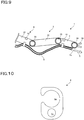
- Fig. 9 is illustrative in schematic of one example of how to attach the manipulator 3 to the sheath 4 in the embodiment described herein
- Fig. 10 is illustrative in schematic of one example of a connector member 6.
- the manipulator 3 includes an end effector 30, a first arm 31, a second arm 32, a third arm 33, a distal-end actuator 34, a first coupler 35, and a second coupler 36.
- the end effector 30 plays a role of the treatment tool for implementing medical treatments such as grasping forceps, local injection needles, electric scalpels or snares.
- an end effector operating unit (not shown) is operated by an operator, it causes the end effector 30 to be actuated by the distal-end actuator 34.
- the distal-end actuator 34 is supported at one end of the first arm 31.
- the first coupler 35 couples together the first and second arms 31 and 32 for relative rotation
- the second coupler 36 couples together the second and third arms 32 and 33 for relative rotation. In turn, this makes the first and second arms 31 and 32 bendable at the first coupler 35 and the second and third arms 32 and 33 bendable at the second coupler 36.
- the sheath 4 has a cable 5a of the treatment tool 5 inserted through it, and is attached to the manipulator 3 by a connector member 6.
- the treatment tool 5 is a member for implementing medical treatments such as grasping forceps, local injection needles, electric scalpels or snares. While a part of the treatment tool 5 is made up of an operating cable 5a, it is to be understood that it may be made up of a flexible tubular member. Assume here that the treatment tool 5 takes the form of holding forceps as an example. An opening/closing operating wire is placed in the tubular member. As shown in Fig.
- a part of the outer circumference of the connector member 6 is cut out to form a notch acting as a manipulator mount 6a, and a round hole acting as a sheath mount 6b is formed in the vicinity of the manipulator mount 6a.
- the manipulator 3 is fitted into the manipulator mount 6a of the connector member 6, and the sheath 4 is inserted through the sheath mount 6b.
- manipulator mount 6a may be formed of a round hole while the sheath mount 6b may be formed of a partially cut out hole. Alternatively, both may be formed of round holes or partially cut out holes.
- the connector member 6 includes a first connector member 61 attached to the first arm 31 and a second connector member 62 attached to the third arm 33.
- the separation between the first connector member 61 and the second connector member 62 is longer than the distance between a first coupler 35 that defines the distal end of the bending portion and a second coupler 36 that defines the proximal end of the bending portion, and the length of the sheath 4 interposed between the first connector member 61 and second connector member 62 is longer than the length of the manipulator 3 between the adjoining first 61 and second connector member 62 along its axial direction.
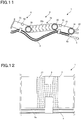
- Fig. 11 is illustrative in schematic of one example of the manipulator 3 having a curving part according to the embodiment described herein.
- a second arm 32 of the manipulator 3 may be made up of a curving arm including a plurality of coupled articulating pieces 32a.
- the second arm 32 is made up of a curving arm too, a portion of the sheath 4 between the connector members 6 comes to have a play enough to bend the manipulator 3 smoothly between the connector members 61 and 62 without interference of the sheath 4 with bending movement of the manipulator 3, resulting in an improved operability.
- the connector members 6 may be mounted in such a way as to be movable toward at least one of the manipulator 3 and sheath 4. It is typically preferable that the connector members 6 are movable in at least one of circumferential and axial directions with respect to the manipulator 3 or sheath 4. Alternatively, at least one of multiple connector members 6 may be movable. Referring typically to the example of Fig. 9 , the first connector member 61 of the first arm 31 may be fixed in place while the second connector member 62 of the third arm 33 may be movable. A sliding bearing or the like may be used for such a movable structure.
- the connector members 6 are movable relative to the manipulator 3, it allows the sheath 4 to move to a position where no active load is applied to it during bending or curving of the manipulator 3 so that even with disturbance like friction, the manipulator 3 can move smoothly.
- Fig. 12 is illustrative in schematic of one example of a mounting area 37 of the manipulator 3 in the embodiment described herein.
- the mounting area 37 of the manipulator 3, to which the connector members 6 are attached may be of reduced friction, as shown in Fig. 12 .
- the mounting area 37 (not shown) of the sheath 4, to which the connector members 6 are attached may be of reduced friction.
- a portion of contact of the connector members 6 with the manipulator 3 may be of reduced friction.
- the mounting area 37 may have been coated with a low-friction material such as fluororesin.
- the sheath 4 can move to a position where no more active load is applied to it during the bending or curving of the manipulator 3 so that even with disturbance like friction, the manipulator 3 can move more smoothly.
- a movement restrictor provided so as to restrict movement of the connector members 6 to a given distance or angle. For instance, when the diameter of the mounting area 37 is smaller than the manipulator 3 adjacent to it, there is a step having a varying diameter left as the movement restrictor that restricts movement of the connector members 6 to a given amount of distance.
- movement restrictors 38 and 39 provided so as to restrict movement of the connector members 6 such that the movement of the connector members 6 comes to a halt in a given position for movement restriction.
- Fig. 13 is illustrative in schematic of one example of the movement restrictor in the embodiment described herein.
- electromagnets are located in given positions such that one of the manipulator 3 and connector member 6 becomes an S-pole 38a and the other an N-pole 38b. And with the intention of stopping movement of the connector member 6 with respect to the manipulator 3, an electric current is passed through the electromagnets such that they attract each other, thereby stopping movement of the connector member 6 with respect to the manipulator 3. For instance, this facilitates insertion of the cable 5a through the sheath 4.
- a permanent magnet may be used for one magnet.
- Fig. 14 is illustrative in schematic of another example of the movement restrictor according to the embodiment described herein.
- a wire or other similar material is wound around the outer circumference of the connector member 6. And with the intention of stopping the connector member 6 with respect to the manipulator 3, the wire may be pulled thereby stopping movement of the connector member 6 with respect to the manipulator 3. For instance, this facilitates insertion of the cable 5a through the sheath 4.
- end effector 30 and treatment tool 5 in the manipulator 3 Actuation of the end effector 30 and treatment tool 5 in the manipulator 3 is now explained.
- two surgical members end effector 30 and treatment tool 5 may be used. It is thus possible to reduce the number of replacement of the treatment tool 5 and, hence, shorten the time needed for replacement.
- Both the end effector 30 and the treatment tool 5 may be operated by the single manipulator 3. It is therefore possible to achieve rapid movement of both the end effector 30 and the treatment tool 5 to an affected site, resulting in an improvement in the operability of the manipulator 3.
- the end effector 30 and treatment tool 5 in the manipulator 3 are individually used, they are preferably actuated, as mentioned below, such that they do not interfere with each other.
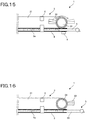
- Fig. 15 is illustrative in schematic of the first actuation state of the end effector 30 and treatment tool 5 in the embodiment described herein.
- a distal-end actuator 34 is actuated to rotate the end effector 30 to the first arm 31 side.
- a sensor 9 may be provided for detection of whether the treatment tool 5 is found or not. When the sensor 9 detects the presence of the treatment tool 5, the end effector 30 is rotated to the first arm 31 side, and when the sensor 9 does not, the end effector 30 is rotated to the opposite side. While the sensor 9 may be located anywhere in the sheath 4, it is preferably located in the vicinity of the distal end. For the sensor 9, use may be made of a transmission sensor, an electrostatic capacity sensor, a proximity sensor or the like.
- Fig. 16 is illustrative in schematic of the second actuation state of the end effector 30 and treatment tool 5 in the embodiment described herein.
- the distal end of the treatment tool 5 extends out from the end effector 30 even with a part of the hard portion 59 of the treatment tool 5 stored in the sheath 4.
- Fig. 17 is illustrative in schematic of the third actuation state of the end effector 30 and treatment tool 5 in the embodiment described herein.
- the cable 5a is pulled to store the treatment tool 5 within the sheath 4.
- a part of the treatment tool 5 may be received within the sheath 4 as depicted in Fig. 17(a) or, alternatively, the treatment tool 5 may be received within the sheath 4 in its entirety, as depicted in Fig. 17(b) .
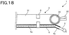
- Fig. 18 is illustrative in schematic of the fourth actuation state of the end effector 30 and treatment tool 5 in the embodiment described herein.
- the end effector 30 and the treatment tool 5 are selectively used.
- a guide 4a is formed over the sheath 4 to extend the treatment tool 5 in such a direction as to space away from the end effector 30.
- Fig. 19 is illustrative in schematic of the fifth actuation state of the end effector 30 and treatment tool 5 in the embodiment described herein.
- the treatment tool 5 is used.
- a grasping member is used as the end effector 30 to fix the sheath 4 by means of the end effector 30 in place. Note here that both the sheath 4 and the treatment tool 5 stored within the sheath 4 may be fixed by means of the end effector 30 in place.
- Fig. 20 is illustrative in schematic of the sixth actuation state of the end effector 30 and treatment tool 5 in the embodiment described herein.
- actuations of the end effector 30 and treatment tool 5 are individually restricted.
- a grasping member 51 is used as the treatment tool 5, and the end effector 30 is grasped by means of the treatment tool 5.
- the end effector 30 is thus grasped by the treatment tool 5 whereby the actuations of the end effector 30 and treatment tool 5 are individually restricted with the result that there can be reduced interference with other endoscope or manipulator.
- the fixation mechanism for temporal fixation of the treatment tool 5 to the sheath 4 in the medical apparatus 1 according to the embodiment described herein is now explained.
- the treatment tool 5 is designed such that it is advanceable and retracable the sheath 4.
- there is the need for using the treatment tool 5 while fixed in place for instance, there is increasing demand for actuation accuracy of the treatment tool 5 during use. It is then possible to fix the treatment tool 5 temporarily to the sheath 4 thereby improving on operability.
- Fig. 21 is illustrative in schematic of one example of the fixation mechanism 7 for temporal fixation of the treatment tool 5 to the sheath 4 in the embodiment described herein.
- the sheath 4 includes an inwardly extending convexity 4b, as depicted in Fig. 21(a) .
- the treatment tool 5 includes a concavity 51a fitted over the convexity 4b.
- the treatment tool 5 includes a diameter-increasing portion 51b whose diameter increases as it comes close to the convexity 51a, a maximal portion 51c where the diameter of the portion 51b reaches a maximum and a lid 51d formed on the distal end side of the concavity 51a and having an increasing diameter.
- the opening in the sheath 4 is covered up by the lid 51d because ingress of foreign matter into the sheath 4 is held back. Letting out the cable 5a of the treatment tool 5 is all that is needed to make the treatment tool 5 movable with respect to the sheath 4. Note here that the sheath 4 may have a concavity while the treatment tool 5 may have a convexity.
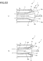
- Fig. 22 is illustrative in schematic of the second example of the fixation mechanism 7 for temporal fixation of the treatment tool 5 to the sheath 4 in the embodiment described herein.
- the sheath 4 includes a tapered portion 4c at its inner circumferential end, as can be seen from Fig. 22(a) .
- the treatment tool 5 includes a diameter-increasing portion 51e whose diameter increases as it comes close to the distal end.
- the second example of the fixation mechanism 7 includes a sandwiched portion 52a held between the sheath 4 and the treatment tool 5.
- the sandwiched portion 52 includes a sandwiched member 52a held between the sheath 4 and the treatment tool 5, and a coupler member 52b coupled at one end to the sandwiched member 52a.
- the other end of the coupler member 52b is coupled to an operating or driving section (not shown) such that it can be pushed or pulled.
- Fig. 23 is illustrative in schematic of the third example of the fixation mechanism 7 for temporal fixation of the treatment tool 5 to the sheath 4 in the embodiment described herein.
- At least one set of adjoining portions 4d extends toward the inner circumferential side of the sheath 4, and is located in adjoining opposite positions with the cable 5a of the treatment tool 5 held between them, as can be seen from Fig. 23(a) .
- a fluid within the flow passage 4 is placed in a high pressure state, as can be seen from Fig. 23(b) .
- the fluid may have been placed in the flow passage 41 beforehand.
- the pressure of the fluid within the flow passage 42 gets high, it causes the sheath 4 formed of a flexible material to be pressed and the cable 5a to be held from both sides for fixation of the treatment tool 5 to the sheath 4.
- Lowering of the pressure of the fluid within the flow passage 41 is all that is needed to make the treatment tool 5 movable with respect to the sheath 4.
- Fig. 24 is illustrative in schematic of the fourth example of the fixation mechanism 7 for temporal fixation of the treatment tool 5 to the sheath 4 in the embodiment described herein.
- a swelling portion 53 is attached to the outer circumference of the cable 5a through the treatment tool 5, as can be seen from Fig. 24(a) .
- the swelling portion 53 is normally attached to the cable 5a in such a way as to be movable between the cable 5a and the sheath 4.
- a fluid such as air or gas is fed into the swelling portion 53, as can be seen from Fig. 24(b) .
- the fluid flows in, it causes the swelling portion 53 to swell out enough to press the sheath 4 for fixation of the treatment tool 5 to the sheath 4.
- a discharge of the fluid out of the swelling portion 53 is all that is needed to make the treatment tool 5 movable with respect to the sheath 4.
- the swelling portion 53 may be attached to the inner circumferential side of the sheath 4. In this case, as the swelling portion 53 swells out, it causes the cable 5a to be held from both its sides for fixation of the treatment tool 5 to the sheath 4. A discharge of the fluid out of the swelling portion 53 is all that is needed to make the treatment tool 5 movable with respect to the sheath 4.
- Fig. 25 is illustrative in schematic of the fifth example of the fixation mechanism 7 for temporal fixation of the treatment tool 5 to the sheath 4 in the embodiment described herein.
- the sheath 4 includes a diameter-reduced portion 4e on the inner circumferential side of its end, as can be seen from
- the treatment tool 5 includes an enlarged portion 54 that is diametrically larger than the inner diameter of the diameter-reduced portion 4e formed on the cable 5a.
- Letting of the cable 5a out of the treatment tool 5 is all that is needed to fix the treatment tool 5 to the sheath 4, as can be seen from Fig. 25(b) .
- the cable 5a As the cable 5a is let out, it causes the enlarged portion 54 to be fitted over the diameter-reduced portion 4e so that the treatment tool 5 is fixed to the sheath 4 while extending out of the sheath 4. It is then preferable that the diameter-reduced portion 4e of the sheath 4 is covered up by the enlarged portion 54 because ingress of foreign matter into the sheath 4 is held back. Pulling the cable 5a of the treatment tool 5 to release the enlarged portion 54 out from the diameter-reduced portion 4e is all that is needed to make the treatment tool 5 movable with respect to the sheath 4.
- Fig. 26 is illustrative in schematic of the sixth example of the fixation mechanism 7 for temporal fixation of the treatment tool 5 to the sheath 4 in the embodiment described herein.
- a tubular member 5b is provided in such a way as to surround the operating cable 5a of the treatment tool 5.
- One end of the tubular member 5b is covered up by a lid 5c, and a hole 5d is formed through the tubular member 5b.
- the other end of the tubular member 5b is connected with a suction device (not shown) capable of sucking air on the inner circumferential side of the tubular member 5b so that there is a flow passage 55 formed on the inner circumferential side of the tubular member 5b.
- the treatment tool 5 is stored in the sheath 4 by pulling the cable 5a or tubular member 5b of the treatment tool 5.
- Fixation of the treatment tool 5 to the sheath 4 may be achieved by pulling the cable 5a or tubular member 5b of the treatment tool 5, and using the suction device (not shown) to suck air in the flow passage 55 while the treatment tool 5 remains stored in the sheath 4, as can be seen from Fig. 26(c) .
- the sucked air sucks the sheath 4 at a place corresponding to the hole 5d.
- the sheath 4 comes into contact with the tubular member 5b of the treatment tool 5 to close up the hole 5d, and is fixed by suction force in place.
- Making the treatment tool 5 movable to the sheath 4 may be achieved by stopping the suction of air in the flow passage 55 and letting out the cable 5a or tubular member 5b of the treatment tool 5.
- Fig. 27 is illustrative in schematic of the seventh example of the fixation mechanism 7 for temporal fixation of the treatment tool 5 to the sheath 4 in the embodiment described herein.
- the cable 5a of the treatment tool 5 is provided with a diameter-increasing portion 51f increasing in diameter toward its distal end.
- the sheath 4 is provided with at least one set of outwardly extending opposite protrusions 4f.
- the retaining member 57 is provided with a hole 57a through which the pressing member 58 can be inserted. Note here that the distal end portion of the pressing member 58 may be tilted in conformity with the tilt of the diameter-increasing portion 51f to facilitate movement of the treatment tool 5.
- the protrusions 4f of the sheath 4 are grasped by the end effector 30.
- the protrusions 4f are grasped by the end effector 30, it causes the pressing member 58 to extend out from the hole 57a formed in the retaining member 57, pressing the diameter-increasing portion 51f of the treatment tool 5.
- the pressing member 58 presses the diameter-increasing portion 51f, it causes the treatment tool 5 to extend out from the distal end of the sheath 4 along the tilt of the diameter-increasing portion 51f.
- the end effector 30 has a grasp of the retaining member 57 via the sheath 4. Then, the cable 5a is sandwiched between the pressing members 58 for fixation of the treatment tool 5 to the sheath 4.
- each of the sheath 4, treatment tool 5 and pressing members 58 is made up of an electrically conductive wire or the like so that electric current can be passed through them in the state of Fig. 27(b) .
- the passage of electric current may be achieved by the operation of a switch on the operating section (not shown).
- a local injection needle or the like mounted on the treatment tool 5 may be moved advanceably and retractably by such passage of electric current as shown in Fig. 27(b) .
- Fig. 28 is illustrative of a medical system 90 to which the medical apparatus 1 according to the embodiment described herein is applied
- Fig. 29 is illustrative in architecture of the medical system 90 to which the medical apparatus 1 according to the embodiment described herein is applied.
- the medical system 90 incorporates the medical apparatus 1 according to the embodiment described herein.
- the medical system 90 includes the medical apparatus 1 including an endoscope/manipulator operating unit 11 operated by an operator O as well as an endoscope 2 and a manipulator 3 (shown in Fig. 1 ) that is capable of insertion through the body of a patient P lying on an operating table BD, for instance, a soft organ like the large intestine, a system control unit 91 for control of the medical apparatus 1, and a display unit 93 for displaying images acquired through the endoscope 2.
- the endoscope/manipulator operating unit 11 includes a pair of operating handles mounted on an operating table, and a footswitch or the like mounted on the face of the floor.
- the endoscope/ manipulator operating unit 11 may include a multi-joint structure.
- the angle of the endoscope/ manipulator operating unit 11 in operation is acquired from an angle acquisition unit such as an encoder, and in response to the acquired signals, the system control unit 91 puts an end effector 30, treatment tool 5, etc. in actuation by way of a driver, as shown in Fig. 29 .
- the endoscope/manipulator control unit 16 shown in Fig. 1 may be installed in the medical apparatus 1 to put the end effector 30, treatment tool 5 or the like in actuation.
- Images acquired through the endoscope 2 are produced out to an image processor unit 92 in the system control unit 91.
- the images processed in the image processor unit 92 are displayed on the display unit 93, and the operator O operates the manipulator 3 while viewing the images displayed on the display unit 93.
- the medical apparatus 1 includes the endoscope 2, the manipulator 3 having at least one degree of freedom, the flexible cylindrical sheath 4 mounted on the outer circumference of the manipulator 3, the treatment tool 5 inserted through the sheath 4, and the endoscope/ manipulator operating unit 11 for operating the endoscope 2 and manipulator 3 independently.
- the treatment tool 5 can more easily be placed within the field of view of the endoscope 2 by mounting the sheath 4 having the treatment tool 5 inserted through it on the manipulator 3 for operation of the endoscope 2 or manipulator 3, thereby improving on operability.
- the medical apparatus 1 includes the endoscope/manipulator control unit 16 for independent control of the endoscope 2 and manipulator 3, wherein the endoscope/manipulator operating unit 11 includes an endoscope operating unit 12 and a manipulator operating unit 13 separately, and the endoscope/manipulator control unit 16 includes an endoscope control unit 17 and a manipulator control unit 18 separately.
- the medical apparatus 1 here is compatible with independent operation of the endoscope 2 and manipulator 3, resulting in a more improved operability.
- the medical apparatus 1 includes a first connector member 61 for connecting together the manipulator 3 and sheath 4, and a second connector member 62 located adjacent to the first connector member 61 for connecting together the manipulator 3 and sheath 4, wherein the length of the sheath 4 located between the adjoining first and second connector members 61 and 62 is longer than the length of the manipulator 3 between the adjoining first and second connector members 61 and 62 in the axial direction of the manipulator 3.
- the sheath 4 between the adjoining first and second connector members 61 and 62 has a play enough to provide smooth bending of the manipulator 3 between the adjoining first and second connector members 61 and 62 without any interference of the sheath 4 with the bending movement of the manipulator 3, resulting in an improved operability.
- the first 61 or the second connector member 62 connects together the manipulator 3 and sheath 4 such that they are relatively movable. Upon bending or curving of the manipulator 3, therefore, the sheath 4 can move to a position where no active load is applied so that even with disturbance such as friction, the manipulator 3 can be smoothly actuated.
- the medical apparatus 1 includes the movement restrictors 38 and 39 for stopping movement of the first 61 or the second connector member 62 in a given position for movement restriction. It is thus possible to stop movement of the connector member 6 with respect to the manipulator 3. For instance, it is possible to facilitate insertion of the cable 5a through the sheath 4.
- the medical apparatus 1 includes the fixation mechanism 7 for temporal fixation in a given position of the treatment tool 5 which can move forward and backward into the sheath 4. It is thus possible to improve on the operability of the treatment tool 5 during use in a fixed state.
- the manipulator 3 includes the end effector 30 for implementing medical treatments, resulting in a decrease in the number of replacement of the treatment tool 5 and a curtailment of the time taken for replacement. It is also possible to operate both the end effector 30 and the manipulator 5 by means of the single manipulator 3. It is thus possible to improve on the operability of the manipulator 3.
- the treatment tool 5 and end effector 30 can be operated in an independent manner so that the medical apparatus 1 can be well compatible with each treatment, resulting in an improved operability.
- the treatment tool 5 can be temporality fixed to the manipulator 3 or the manipulator 3 can be temporality fixed to the treatment tool 5 so that the treatment tool 5 can be actuated in a stable manner. It is also possible to reduce interference of the treatment tool 5 with other endoscope or manipulator.
- the medical system 90 includes the system control unit 91 for control of the medical apparatus 1 and the display unit 93 for displaying images acquired through the endoscope 2.
- the system control unit 91 enables images obtained through the endoscope 2 to be shown on the display unit 93 so that it is possible for the operator to actuate the endoscope 2 and manipulator 3 more unerringly as circumstances demand, resulting in a more improved operability.
Landscapes
- Health & Medical Sciences (AREA)
- Life Sciences & Earth Sciences (AREA)
- Surgery (AREA)
- Engineering & Computer Science (AREA)
- Heart & Thoracic Surgery (AREA)
- Molecular Biology (AREA)
- Nuclear Medicine, Radiotherapy & Molecular Imaging (AREA)
- Veterinary Medicine (AREA)
- Public Health (AREA)
- General Health & Medical Sciences (AREA)
- Biomedical Technology (AREA)
- Animal Behavior & Ethology (AREA)
- Medical Informatics (AREA)
- Pathology (AREA)
- Physics & Mathematics (AREA)
- Biophysics (AREA)
- Radiology & Medical Imaging (AREA)
- Optics & Photonics (AREA)
- Oral & Maxillofacial Surgery (AREA)
- Signal Processing (AREA)
- Cardiology (AREA)
- Plasma & Fusion (AREA)
- Otolaryngology (AREA)
- Robotics (AREA)
- Surgical Instruments (AREA)
- Endoscopes (AREA)
Applications Claiming Priority (2)
| Application Number | Priority Date | Filing Date | Title |
|---|---|---|---|
| JP2014013918A JP6192550B2 (ja) | 2014-01-29 | 2014-01-29 | 医療装置及び医療システム |
| PCT/JP2015/051782 WO2015115317A1 (ja) | 2014-01-29 | 2015-01-23 | 医療装置及び医療システム |
Publications (2)
| Publication Number | Publication Date |
|---|---|
| EP3100686A1 true EP3100686A1 (de) | 2016-12-07 |
| EP3100686A4 EP3100686A4 (de) | 2017-10-18 |
Family
ID=53756891
Family Applications (1)
| Application Number | Title | Priority Date | Filing Date |
|---|---|---|---|
| EP15742852.5A Withdrawn EP3100686A4 (de) | 2014-01-29 | 2015-01-23 | Medizinische vorrichtung und medizinisches system |
Country Status (5)
| Country | Link |
|---|---|
| US (1) | US20160331208A1 (de) |
| EP (1) | EP3100686A4 (de) |
| JP (1) | JP6192550B2 (de) |
| CN (1) | CN105934207B (de) |
| WO (1) | WO2015115317A1 (de) |
Cited By (2)
| Publication number | Priority date | Publication date | Assignee | Title |
|---|---|---|---|---|
| US9688365B2 (en) | 2012-07-09 | 2017-06-27 | Fin Control Systems Pty Limited | Fin plug for water craft |
| US9957021B2 (en) | 2012-11-14 | 2018-05-01 | Fin Control Systems Pty. Limited | Fin plug for a water craft |
Families Citing this family (10)
| Publication number | Priority date | Publication date | Assignee | Title |
|---|---|---|---|---|
| EP2979619B1 (de) * | 2013-03-29 | 2018-10-31 | FUJIFILM Corporation | Vorrichtung für endoskopische chirurgie |
| JP5976924B2 (ja) * | 2013-03-29 | 2016-08-24 | 富士フイルム株式会社 | 内視鏡下外科手術装置 |
| JP5959723B2 (ja) * | 2013-03-29 | 2016-08-02 | 富士フイルム株式会社 | 内視鏡下外科手術装置 |
| KR102650270B1 (ko) | 2016-01-11 | 2024-03-21 | 메이저 로보틱스 엘티디. | 수술용 로봇 시스템 |
| US11950869B2 (en) * | 2017-08-30 | 2024-04-09 | Intuitive Surgical Operations, Inc. | System and method for providing on-demand functionality during a medical procedure |
| MX2020006069A (es) | 2017-12-11 | 2020-11-06 | Auris Health Inc | Sistemas y metodos para arquitecturas de insercion basadas en instrumentos. |
| CN210185692U (zh) * | 2018-07-31 | 2020-03-27 | 深圳市精锋医疗科技有限公司 | 可调节从操作设备组件及手术机器人 |
| CN118512134A (zh) * | 2018-10-19 | 2024-08-20 | 奥林巴斯株式会社 | 内窥镜用处置器具 |
| CN116687515B (zh) * | 2023-07-14 | 2026-02-10 | 张伟 | 一种无护筒管腹腔镜手术器械、穿刺器及组装方法 |
| WO2025153571A1 (en) | 2024-01-15 | 2025-07-24 | Symphera Gmbh | Improved microinvasive surgery device |
Family Cites Families (14)
| Publication number | Priority date | Publication date | Assignee | Title |
|---|---|---|---|---|
| JP3255448B2 (ja) | 1992-04-30 | 2002-02-12 | オリンパス光学工業株式会社 | 内視鏡装置 |
| US6921361B2 (en) * | 2000-07-24 | 2005-07-26 | Olympus Corporation | Endoscopic instrument for forming an artificial valve |
| DE10139153A1 (de) * | 2001-08-09 | 2003-02-27 | Ingo F Herrmann | Einweg-Endoskopmantel |
| US7487948B2 (en) * | 2003-08-01 | 2009-02-10 | Ken Gardner | Support for survey rod |
| JP2005137423A (ja) * | 2003-11-04 | 2005-06-02 | Olympus Corp | 内視鏡用の外付けチャンネルおよび外付けチャンネル用分岐部材 |
| EP1740084A2 (de) * | 2004-04-15 | 2007-01-10 | Wilson-Cook Medical Inc. | Endoskopische chirurgische zugangsvorrichtungen und verfahren zur gliederung eines externen zugangskanals |
| JP2005334237A (ja) * | 2004-05-26 | 2005-12-08 | Olympus Corp | 内視鏡装置 |
| JP4302602B2 (ja) * | 2004-09-24 | 2009-07-29 | オリンパス株式会社 | 内視鏡用処置具及び内視鏡処置システム並びに支持アダプタ |
| WO2008093316A1 (en) * | 2007-01-30 | 2008-08-07 | Vision - Sciences Inc. | System and method for navigating a tool within a body conduit |
| JP4914735B2 (ja) * | 2007-02-14 | 2012-04-11 | オリンパスメディカルシステムズ株式会社 | 処置具の位置制御を行う内視鏡システム |
| JP5111931B2 (ja) * | 2007-05-07 | 2013-01-09 | オリンパスメディカルシステムズ株式会社 | 内視鏡用処置具 |
| EP2337488B1 (de) * | 2008-07-18 | 2016-05-25 | Boston Scientific Scimed, Inc. | Geführtes endoskop |
| US8808170B2 (en) * | 2010-03-10 | 2014-08-19 | Mark A. Stern | Multiple-channel endoscopic biopsy sheath |
| JP2012070933A (ja) * | 2010-09-28 | 2012-04-12 | Olympus Corp | 着脱機構、及び術具システム |
-
2014
- 2014-01-29 JP JP2014013918A patent/JP6192550B2/ja active Active
-
2015
- 2015-01-23 CN CN201580005893.1A patent/CN105934207B/zh active Active
- 2015-01-23 EP EP15742852.5A patent/EP3100686A4/de not_active Withdrawn
- 2015-01-23 WO PCT/JP2015/051782 patent/WO2015115317A1/ja not_active Ceased
-
2016
- 2016-07-29 US US15/223,083 patent/US20160331208A1/en not_active Abandoned
Cited By (4)
| Publication number | Priority date | Publication date | Assignee | Title |
|---|---|---|---|---|
| US9688365B2 (en) | 2012-07-09 | 2017-06-27 | Fin Control Systems Pty Limited | Fin plug for water craft |
| US9862467B2 (en) | 2012-07-09 | 2018-01-09 | Fin Control Systems Pty Limited | Securing mechanism for water craft fin |
| US10377452B2 (en) | 2012-07-09 | 2019-08-13 | Fin Control Systems Pty Limited | Fin plug for water craft |
| US9957021B2 (en) | 2012-11-14 | 2018-05-01 | Fin Control Systems Pty. Limited | Fin plug for a water craft |
Also Published As
| Publication number | Publication date |
|---|---|
| US20160331208A1 (en) | 2016-11-17 |
| WO2015115317A1 (ja) | 2015-08-06 |
| CN105934207B (zh) | 2018-12-28 |
| EP3100686A4 (de) | 2017-10-18 |
| JP6192550B2 (ja) | 2017-09-06 |
| JP2015139552A (ja) | 2015-08-03 |
| CN105934207A (zh) | 2016-09-07 |
Similar Documents
| Publication | Publication Date | Title |
|---|---|---|
| EP3100686A1 (de) | Medizinische vorrichtung und medizinisches system | |
| US11903559B2 (en) | Surgeon controlled endoscope device and method | |
| JP6064100B1 (ja) | マニピュレータ及びマニピュレータシステム | |
| CN105101899B (zh) | 医疗器具和医疗系统 | |
| EP2085017B1 (de) | Medizinisches Instrument | |
| EP3123963B1 (de) | Chirurgische endoskopvorrichtung, chirurgisches werkzeug und führungselement | |
| EP2119402A2 (de) | Endoskopievorrichtung | |
| EP3284421B1 (de) | Bedienteil für biegbares behandlungswerkzeug | |
| US11071600B2 (en) | Medical treatment tool and surgical system | |
| EP2679138A1 (de) | Endoskop | |
| JP6211232B1 (ja) | チャネルシース及び医療システム | |
| US20170007346A1 (en) | Treatment device and surgical system | |
| EP3275385A1 (de) | Endoskopische chirurgische vorrichtung und mantelschlauch | |
| US20170071458A1 (en) | Guiding device and surgical system | |
| US12213692B2 (en) | Treatment tool for endoscope | |
| US11911002B2 (en) | Overtube device | |
| JP2013066638A (ja) | 内視鏡 | |
| US12343031B2 (en) | Treatment tool for endoscope | |
| EP3590411B1 (de) | Flexibler mechanismus | |
| US10420573B2 (en) | Surgical tool | |
| US20210307771A1 (en) | Articulating lumen with a grasping end effector | |
| US12453569B2 (en) | Treatment tool for endoscope | |
| US12484766B2 (en) | Treatment tool for endoscope |
Legal Events
| Date | Code | Title | Description |
|---|---|---|---|
| PUAI | Public reference made under article 153(3) epc to a published international application that has entered the european phase |
Free format text: ORIGINAL CODE: 0009012 |
|
| STAA | Information on the status of an ep patent application or granted ep patent |
Free format text: STATUS: REQUEST FOR EXAMINATION WAS MADE |
|
| 17P | Request for examination filed |
Effective date: 20160729 |
|
| AK | Designated contracting states |
Kind code of ref document: A1 Designated state(s): AL AT BE BG CH CY CZ DE DK EE ES FI FR GB GR HR HU IE IS IT LI LT LU LV MC MK MT NL NO PL PT RO RS SE SI SK SM TR |
|
| AX | Request for extension of the european patent |
Extension state: BA ME |
|
| DAX | Request for extension of the european patent (deleted) | ||
| A4 | Supplementary search report drawn up and despatched |
Effective date: 20170920 |
|
| RIC1 | Information provided on ipc code assigned before grant |
Ipc: A61B 17/00 20060101ALI20170914BHEP Ipc: A61B 90/57 20160101ALI20170914BHEP Ipc: A61B 17/29 20060101ALN20170914BHEP Ipc: A61B 17/34 20060101ALN20170914BHEP Ipc: A61B 1/00 20060101AFI20170914BHEP Ipc: A61B 34/30 20160101ALN20170914BHEP |
|
| STAA | Information on the status of an ep patent application or granted ep patent |
Free format text: STATUS: EXAMINATION IS IN PROGRESS |
|
| 17Q | First examination report despatched |
Effective date: 20190215 |
|
| STAA | Information on the status of an ep patent application or granted ep patent |
Free format text: STATUS: THE APPLICATION IS DEEMED TO BE WITHDRAWN |
|
| 18D | Application deemed to be withdrawn |
Effective date: 20190626 |