EP3100809B1 - Appareil de coupe de clé - Google Patents
Appareil de coupe de clé Download PDFInfo
- Publication number
- EP3100809B1 EP3100809B1 EP16168604.3A EP16168604A EP3100809B1 EP 3100809 B1 EP3100809 B1 EP 3100809B1 EP 16168604 A EP16168604 A EP 16168604A EP 3100809 B1 EP3100809 B1 EP 3100809B1
- Authority
- EP
- European Patent Office
- Prior art keywords
- key
- operable
- camera
- calibration
- measurement station
- Prior art date
- Legal status (The legal status is an assumption and is not a legal conclusion. Google has not performed a legal analysis and makes no representation as to the accuracy of the status listed.)
- Active
Links
Images



Classifications
-
- B—PERFORMING OPERATIONS; TRANSPORTING
- B23—MACHINE TOOLS; METAL-WORKING NOT OTHERWISE PROVIDED FOR
- B23C—MILLING
- B23C3/00—Milling particular work; Special milling operations; Machines therefor
- B23C3/28—Grooving workpieces
- B23C3/35—Milling grooves in keys
-
- G—PHYSICS
- G02—OPTICS
- G02B—OPTICAL ELEMENTS, SYSTEMS OR APPARATUS
- G02B13/00—Optical objectives specially designed for the purposes specified below
- G02B13/001—Miniaturised objectives for electronic devices, e.g. portable telephones, webcams, PDAs, small digital cameras
- G02B13/0055—Miniaturised objectives for electronic devices, e.g. portable telephones, webcams, PDAs, small digital cameras employing a special optical element
- G02B13/0065—Miniaturised objectives for electronic devices, e.g. portable telephones, webcams, PDAs, small digital cameras employing a special optical element having a beam-folding prism or mirror
-
- B—PERFORMING OPERATIONS; TRANSPORTING
- B23—MACHINE TOOLS; METAL-WORKING NOT OTHERWISE PROVIDED FOR
- B23C—MILLING
- B23C3/00—Milling particular work; Special milling operations; Machines therefor
- B23C3/28—Grooving workpieces
- B23C3/35—Milling grooves in keys
- B23C3/355—Holders for the template keys
-
- B—PERFORMING OPERATIONS; TRANSPORTING
- B23—MACHINE TOOLS; METAL-WORKING NOT OTHERWISE PROVIDED FOR
- B23Q—DETAILS, COMPONENTS, OR ACCESSORIES FOR MACHINE TOOLS, e.g. ARRANGEMENTS FOR COPYING OR CONTROLLING; MACHINE TOOLS IN GENERAL CHARACTERISED BY THE CONSTRUCTION OF PARTICULAR DETAILS OR COMPONENTS; COMBINATIONS OR ASSOCIATIONS OF METAL-WORKING MACHINES, NOT DIRECTED TO A PARTICULAR RESULT
- B23Q17/00—Arrangements for observing, indicating or measuring on machine tools
- B23Q17/24—Arrangements for observing, indicating or measuring on machine tools using optics or electromagnetic waves
-
- B—PERFORMING OPERATIONS; TRANSPORTING
- B23—MACHINE TOOLS; METAL-WORKING NOT OTHERWISE PROVIDED FOR
- B23Q—DETAILS, COMPONENTS, OR ACCESSORIES FOR MACHINE TOOLS, e.g. ARRANGEMENTS FOR COPYING OR CONTROLLING; MACHINE TOOLS IN GENERAL CHARACTERISED BY THE CONSTRUCTION OF PARTICULAR DETAILS OR COMPONENTS; COMBINATIONS OR ASSOCIATIONS OF METAL-WORKING MACHINES, NOT DIRECTED TO A PARTICULAR RESULT
- B23Q17/00—Arrangements for observing, indicating or measuring on machine tools
- B23Q17/24—Arrangements for observing, indicating or measuring on machine tools using optics or electromagnetic waves
- B23Q17/2452—Arrangements for observing, indicating or measuring on machine tools using optics or electromagnetic waves for measuring features or for detecting a condition of machine parts, tools or workpieces
- B23Q17/2471—Arrangements for observing, indicating or measuring on machine tools using optics or electromagnetic waves for measuring features or for detecting a condition of machine parts, tools or workpieces of workpieces
-
- B—PERFORMING OPERATIONS; TRANSPORTING
- B23—MACHINE TOOLS; METAL-WORKING NOT OTHERWISE PROVIDED FOR
- B23Q—DETAILS, COMPONENTS, OR ACCESSORIES FOR MACHINE TOOLS, e.g. ARRANGEMENTS FOR COPYING OR CONTROLLING; MACHINE TOOLS IN GENERAL CHARACTERISED BY THE CONSTRUCTION OF PARTICULAR DETAILS OR COMPONENTS; COMBINATIONS OR ASSOCIATIONS OF METAL-WORKING MACHINES, NOT DIRECTED TO A PARTICULAR RESULT
- B23Q35/00—Control systems or devices for copying directly from a pattern or a master model; Devices for use in copying manually
- B23Q35/04—Control systems or devices for copying directly from a pattern or a master model; Devices for use in copying manually using a feeler or the like travelling along the outline of the pattern, model or drawing; Feelers, patterns, or models therefor
- B23Q35/08—Means for transforming movement of the feeler or the like into feed movement of tool or work
- B23Q35/12—Means for transforming movement of the feeler or the like into feed movement of tool or work involving electrical means
- B23Q35/127—Means for transforming movement of the feeler or the like into feed movement of tool or work involving electrical means using non-mechanical sensing
- B23Q35/128—Sensing by using optical means
-
- E—FIXED CONSTRUCTIONS
- E05—LOCKS; KEYS; WINDOW OR DOOR FITTINGS; SAFES
- E05B—LOCKS; ACCESSORIES THEREFOR; HANDCUFFS
- E05B19/00—Keys; Accessories therefor
- E05B19/0011—Key decoders
-
- G—PHYSICS
- G06—COMPUTING OR CALCULATING; COUNTING
- G06V—IMAGE OR VIDEO RECOGNITION OR UNDERSTANDING
- G06V10/00—Arrangements for image or video recognition or understanding
- G06V10/10—Image acquisition
-
- G—PHYSICS
- G06—COMPUTING OR CALCULATING; COUNTING
- G06V—IMAGE OR VIDEO RECOGNITION OR UNDERSTANDING
- G06V20/00—Scenes; Scene-specific elements
- G06V20/60—Type of objects
- G06V20/66—Trinkets, e.g. shirt buttons or jewellery items
-
- B—PERFORMING OPERATIONS; TRANSPORTING
- B23—MACHINE TOOLS; METAL-WORKING NOT OTHERWISE PROVIDED FOR
- B23C—MILLING
- B23C2235/00—Details of milling keys
- B23C2235/21—Calibration by electronic detection of position of probes and cutting wheels
-
- B—PERFORMING OPERATIONS; TRANSPORTING
- B23—MACHINE TOOLS; METAL-WORKING NOT OTHERWISE PROVIDED FOR
- B23C—MILLING
- B23C2235/00—Details of milling keys
- B23C2235/32—Measurement systems
-
- B—PERFORMING OPERATIONS; TRANSPORTING
- B23—MACHINE TOOLS; METAL-WORKING NOT OTHERWISE PROVIDED FOR
- B23C—MILLING
- B23C2235/00—Details of milling keys
- B23C2235/41—Scanning systems
-
- B—PERFORMING OPERATIONS; TRANSPORTING
- B23—MACHINE TOOLS; METAL-WORKING NOT OTHERWISE PROVIDED FOR
- B23C—MILLING
- B23C2235/00—Details of milling keys
- B23C2235/48—Tracers, probes or styli
Definitions
- the present invention relates to key a key cutting apparatus according to the preamble of claim 1.
- An example of such an apparatus is disclosed by US 5,908,273 A .
- keys it is a common requirement for keys to be duplicated. For example, a new lock fitted to an external door may be provided initially with a small number of keys which are then duplicated to provide sufficient keys for all users of the door. Traditionally, this requires one of the original keys to be taken to a key cutting service where an experienced operator will select a suitable key blank from an available stock of blanks, and then cut the selected blank to duplicate the original key.
- Examples of the present disclosure provide key cutting apparatus comprising:
- the test object may provide a plurality of surfaces at respective positions in the field of illumination of the light source, the illumination of each of the surfaces being visible to the camera, during use.
- the positions may be at respective distances from the camera.
- the plurality of surfaces may be parallel and planar.
- one of the surfaces may be a centreline surface at a position corresponding with the centreline of an original key placed in the measurement station.
- the test object may provide at least one further surface which is closer to and/or further from the camera source than the centreline surface.
- the test object may comprise a plurality of stacked sheets, the sheets having apertures to expose part of any lower sheets in the stack.
- the camera may measure the width of a patch of illumination on each of the surfaces to measure the focus position of the light source relative to the surfaces.
- the light source may project a line to illuminate the measurement station during calibration, wherein the camera observes the orientation of the line to calibrate the orientation of the light source.
- the apparatus may be operable to adjust the focus and/or orientation of the light source according to measurements taken when the test object is illuminated.
- Examples of the present disclosure also provide key cutting apparatus comprising:
- the opaque edges may be parallel.
- the calibration features may be notches or prominences.
- the apparatus may be operable to adjust the orientation of the camera according to the detected orientation.
- the apparatus may be operable to move the camera, relative to the calibration member, to move the edges and/or the line of the calibration features across the field of view of the camera.
- Examples of the present disclosure also provide key cutting apparatus comprising:
- a grooved jaw may be fixed in position relative to the workstation, and a movable jaw provided to clamp against the fixed jaw.
- the fixed jaw may be a lower jaw, the movable jaw being an upper jaw.
- the movable jaw may be generally flat and have at least one edge relieved by a chamfer or radius.
- the movable jaw may be mounted at a pivot, the apparatus comprising an actuator to move the movable jaw, and wherein the pivot is loose to allow the movable jaw to accommodate a range of sizes of key blank.
- Examples of the present disclosure also provide key cutting apparatus comprising:
- the calibration member may be maintained at a fixed calibration position, and the apparatus may further comprise drive means operable to provide relative movement between the workstation, the calibration member and the cutting device.
- the drive means may be operable to bring to the calibration tip a position on the surface of the key blank which is away from the edges of the cut. The position may be at a centreline of the key blank.
- Examples of the present disclosure also provide key cutting apparatus comprising:
- the apparatus may be operable to analyse the usage record to determine and/or to predict when the deburring tool is worn out.
- Examples of the present disclosure also provide key cutting apparatus comprising:
- the measurement station may measure the shank length of the original key.
- the measurement station may detect the shoulder of an original key, and measure the blade length of the key, from the shoulder.
- the measurement station may measure the tip profile of the key tip and the cutting system may be operable to reproduce the measured tip profile on the key blank after the key blank has been cut to length.
- the key cutting apparatus to be described herein is primarily intended for use in cutting keys for cylinder locks or mortice locks such as are in widespread use.
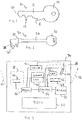
- Fig 1 illustrates the outline of a typical cylinder key 10.
- the key 10 has an elongate blade 12 which meets a grip 14 at a shoulder 16.
- the blade 12 is inserted into a cylinder lock (not shown), while held by means of the grip 14, and can then be turned by means of the grip 14, to operate the lock.
- the shoulder 16 limits the depth of penetration of the blade 12 into the lock.
- One edge 18 of the blade 12 is cut to the appropriate shape for operating the levers of the cylinder lock.
- the edge 18 must be cut so that the formations along the edge 18 are correctly positioned within the lock, when the blade 12 is fully inserted into the lock, up to the limit set by the shoulder 16.
- the total length of the blade 12 must be appropriate for the corresponding lock, so that the tip 20 is positioned appropriately within the lock.
- the tip 20 may be required to operate a clutch mechanism or other additional security mechanism.
- Fig 2 illustrates the outline of a typical mortice key 22.
- the key 22 has a shank 24 having a grip 26 at one end and carrying a blade 28 near the other end of the shank 24.
- the blade 28 has an edge 30 cut to an appropriate shape for operation of the levers of a mortice lock with which the key 22 is to be used.
- the edge 30 must be cut so that the formations along the edge 30 are correctly positioned within the lock, when the blade 28 is fully inserted into the lock, up to the limit set by a shoulder 32 formed on the shank 24.
- Fig 3 illustrates, in simple block diagram form, a key cutting apparatus 34.
- the apparatus 34 has a measurement station indicated generally at 36 and operable, as will be described, to measure an original key to be copied.
- the apparatus 34 also has a workstation indicated generally at 38 and operable, as will be described, to hold a key blank to be cut as a copy of an original key measured by the measurement station 36.
- the apparatus 34 also has a cutting system indicated generally at 40 and operable, as will be described, to cut a key blank held in the workstation 38, in accordance with measurements made by the measurement station 36.
- the measurement station 36 includes a transparent platen 42 on which an original key can be laid for measurement.
- a light source 44 is provided for illuminating the platen 42 during measurement.
- the light source 44 may be a laser.
- a camera 46 is provided for observing an original key when laid on the platen 42 and illuminated by the laser 44.
- a backlight 47 is positioned behind the platen 42 (as seen from the camera 46 and serves to create a silhouette of the original key, when viewed by the camera 46.
- the workstation 38 includes a clamp at 48, in which a key blank can be held while being cut.
- Cutting is effected by the cutting system 40 which, in this example, includes a cutting device such as a cutting wheel (not illustrated in Fig 3 ) and may also include finishing tools such as a deburring wheel (not illustrated in Fig 3 ).
- the process of cutting a key blank held in the clamp 48 is achieved by relative movement of the workstation 38 and the cutting system 40, driven by a drive arrangement 50.
- the drive arrangement 50 may include, for example, electric motors or other actuators, and transducers for measuring movement, such as shaft encoders.
- Calibration arrangements indicated generally at 52 are provided in association with the cutting system 40, and will be described more fully below.
- a control arrangement 54 which may be based around a microprocessor or other computing device, is connected to control the operation of the components of the apparatus 34, in the manner which will be described.
- the control arrangement 54 may also control a user display 56, which may provide feedback or instructions to a user, during use of the apparatus 34.
- the control arrangement 54 may incorporate the calibration arrangements 52, but the calibration arrangements 52 are here shown and described separately, in the interests of clarity.
- the measuring station 36 is accessible to a user through a door 58.
- the workstation 38 is accessible to a user through a door 60.
- the doors 58, 60 may be controlled by locks or override switches, for safety reasons.
- the apparatus 34 provides storage 62 for a stock of a wide selection of key blanks of different designs and sizes.
- the existing key (here called an "original key") is placed on the platen 42.
- the original key is then illuminated by the laser 44 and the backlight 47 and viewed by the camera 46 in order to measure the original key.
- the control apparatus 54 may indicate the required selection of key blank to the user, using the display 56, allowing the user to select the appropriate key blank from the stock at 62.
- the key blank is then placed into the workstation 38. Once the doors 58, 60 are both closed, the control arrangement 54 can initiate the cutting process in which the drive arrangement 50 causes the cutting system 40 to cut the key blank to reproduce the original key. This process is controlled by the measurements which have been taken from the original key by means of the camera 46.
- the light source 44 It is desirable for the light source 44 to be focused appropriately, so that an original key is illuminated by a sharp patch of light, such as a line of light which is then moved across the original key, to scan the key.
- This line of light is viewed by the camera 46, so that the scanning process allows the shape and size of the original key to be measured.
- a sharp line of light for scanning in this manner can be achieved by appropriately setting the focus of the laser 44.
- a test object 64 is provided ( Fig 4 ). When used for calibration, the test object 64 is placed on the platen 42 and illuminated by the laser 44. When placed in the measurement station 36, the test object 64 allows the camera 46 to obtain calibration measurements relating to the laser 44.
- the test object 64 provides a plurality of surfaces 66a-c which will be at respective positions in the field of illumination of the laser 44.
- the positions are at respective distances from the camera 46.
- the illumination of each of the surfaces 66a-c will be visible to the camera 46, during use.
- the plurality of surfaces 66a-c are parallel and planar, being the parallel surfaces of a plurality of stacked sheets 68a-c.
- Each sheet 68a-b has an aperture 70a-b to expose part of the lower sheets 68b-c and in particular, part of the surfaces 66b-c.
- the upper sheet 68a has a relatively large aperture 70a and lies on the middle sheet 68b.
- the upper surface 66a of the upper sheet 68a is exposed, around the aperture 70a.
- the middle sheet 68b has an aperture 70b which is smaller than the large aperture 70a, so that part of the upper surface 66b of the middle sheet 68b is exposed through the aperture 70a.
- the lower sheet 68c has no aperture, so that part of the upper surface 66c of the lower sheet 68c is exposed through the apertures 70a and 70b.
- the three upper surfaces 66a-c are exposed to the view of the camera 46 and are positioned at three respective heights above the plane of the platen 42.
- One of the surfaces (the middle surface 66b, in this example) is at a position which corresponds with the typical height of the centreline of an original key placed in the measurement station 36 (on the platen 42), and is therefore termed the centreline surface.
- One of the further surfaces 66a is closer to the camera 46 than the centreline surface, and the other surface 66c is further from the camera 46 than the centreline surface.
- Fig 5 illustrates part of the image seen by the camera 46 when the test object 64 is illuminated by a focused line 72 of light from the laser 44.
- the laser line 72 falls across the surfaces 66a-c but because the surfaces 66a-c are at different heights, the line 72 will not be sharply focused on all of the surfaces 66a-c.
- a sharp line of light is seen on the centreline surface 66b. Broad lines of light are seen on the other two surfaces 66a, 66c. This corresponds with the laser being focused at the height of the centreline surface 66b.
- a sharp line of light is seen on the lower surface 66c.
- the test object 64 also allows the orientation of the laser 44 to be calibrated. This can be seen from Fig 6 , in which a laser line 72 is visible on the upper surface 66a of the test object 64, and which intersects the edges 74 of the test object 64 at two positions 76. If the test object 64 is held at a known position on the platen 42, then the orientation of the laser 44 can be judged by considering the positions of the intersections 76, allowing the calibration arrangements 52 to modify the orientation of the laser 44, if required.
- Fig 7 shows the measurement station 36 in more detail, with the camera 46 positioned to view the platen 42 through an optical system indicated at 78.
- An original key 80 is indicated on the platen 42 in Fig 7 . This is illustrated at the measurement position at which an original key will normally be placed for measurement.
- a calibration member 82 is mounted between the backlight 47 and the platen 42.
- Fig 8 represents the image seen by the camera 46 when looking at the platen 42 and the original key 80. It can be seen from Fig 8 that the calibration member 82 provides a gap, generally at 84, between opaque edges 86.
- the gap 84 is visible to the camera 46, behind the original key 80.
- the original key 80 at its measurement position, is seen by the camera 46 as being located within the gap 84.
- the gap 84 may be provided as an aperture in a plate, but that the only parts of the boundary of the aperture within the field of view of the camera 46 are the two, parallel lengths of the edges 86, as shown in Fig 8 .
- Each of the edges 86 has a calibration feature 88 detectable in the image captured by the camera 46.
- the calibration features 88 are notches in the otherwise straight edges 86.
- one or both of the calibration features 88 may be prominences.
- the image from the camera 46 can be analysed to identify the calibration features 88 and a notional line 90, which joins the features 88.
- the current alignment of the camera 46 can be determined by considering the angle of the notional line 90, within the image ( Fig 8 ). If necessary, the calibration arrangement 52 may turn the camera 46 around the viewing direction 91 ( Fig 7 ), until the notional line 90 lies at the required angle within the image, thereby calibrating the orientation of the camera 46.
- Camera alignment may also be calibrated, as follows.
- the calibration member 82 creates two opaque margins in the image seen by the camera 46.
- the position of the camera 46 may be adjusted until the margins are of equal width.
- the position of the camera 46 may also be adjusted until the notional line 90 is central in the field of view of the camera 46.
- the field of view of the camera 46 may be adjusted in two perpendicular directions across the plane of the platen 42, and also adjusted in orientation around an axis perpendicular to the plane of the platen 42.
- the workstation 38 incorporates a clamp mechanism 92 illustrated schematically in Fig 9 .
- the clamp mechanism 92 is used to hold a key blank while the key blank is being cut by the cutting system 40.
- the clamp mechanism 92 includes a first jaw 94 and a second jaw 96.
- the jaw 94 is mounted at a fixed position within the workstation 38.
- the jaw 96 is mounted at one end of an arm 98.
- the other end of the arm 98 is pivotally mounted at a pivot 100.
- the pivot 100 is loose, meaning that a slot 102 on the arm 98 is over size for a pivot pin 104, so that the arm 98 is not restricted solely to pivoting movement, but can also move longitudinally, to a limited extent. This freedom allows different sizes of key blank to be accommodated conveniently, as will become apparent.
- the position of the arm 98 is controlled by an actuator arrangement 106, under the control of the control arrangement 54, allowing the arm 98 to be raised or lowered, thereby closing or opening the jaws 94, 96 to clamp or release a key blank.
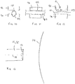
- the jaw 94 has a groove 108, best seen in Fig 10 and Fig 11 .
- the groove 108 receives the shank 110 of a mortice key.
- the jaw 96 can then be closed against the jaw 94 by operation of the actuator 106 in order to clamp the shank 110 between the jaws 94, 96.
- the shank 110 is forced down into the groove 108 and the longitudinal alignment of the shank 110 is therefore forced to an alignment defined by the orientation of the groove 108.
- the groove 108 is V-shaped to allow for this action with a range of different shank diameters.
- only the jaw 94 has a groove 108, but a groove could also, or alternatively, be provided in the jaw 96.
- the lower jaw 94 is fixed; the upper jaw 96 is movable.
- the loose pivot 100 further provides for accurate alignment of the shank 110 in the groove 108. This is because the looseness in the pivot 100 allows the jaw 96 to adjust its position slightly, as the jaws close, to accommodate size differences between different shanks, but nevertheless ensures that a clamping force is provided to clamp the shank 110 and to press the shank 110 into the groove 108, to create the preferred alignment, as discussed above.
- Fig 12 illustrates a further feature of the upper jaw 96.
- a chamfer 112 is formed along that edge of the jaw 96 which is closest to the pivot 100.
- a radius may be formed on the jaw 96, indicated by broken line 113.
- a chamfer 112 or radius 113 helps prevent a key blank being knocked out of position, as could happen by engagement between the shank 110 and a square edge of the jaw 96.
- the presence of a chamfer or radius feature, together with the looseness of the pivot 100 has been found to achieve good grip and good alignment for the shank 110.
- Fig 13 illustrates (on an enlarged scale) an edge 18, 30 of a key blank, and part of the circumference of a cutting device 114, illustrated as an abrasive disc.
- Relative movement of the workstation 38 and the cutting system 40, as described above, allows the abrasive disc 114 to engage the edge 18, 30 to create a cut, indicated by a broken line 116.
- the surface defined by the broken line 116 will be part of the arc of a circular cylinder. That is, the surface will not be flat. However, the radius of curvature may be very high, relative to the dimensions of the edge 18, 30.
- the reliability of the key cutting process can be improved by calibrating the cutting system 40 by reference to the height of the centre line 118. In particular, this calibrates the cutting system 40 at the same height as the test object 64 is used to calibrate the focus of the laser 44.
- Calibration can be achieved by first making a test cut of a key blank or a test blank, in the manner described in relation to Fig 13 and then offering the surface of the test cut 116 to a calibration member in the form of a probe 120 illustrated in Fig 14 .
- the probe 120 has a calibration tip 122 and when calibration is required, the drive arrangement 50 brings the surface 116 to the calibration tip 122. In one example, this is achieved by holding the probe 120 at a fixed calibration position, and allowing the drive arrangement 50 to provide relative movement between the workstation 38, the cutting system 40 and the calibration probe 120, so that the test cut 116 can be made by the abrasive disc 114, and then calibrated by the calibration tip 122.
- the cutting system 40 may include a deburring function, as discussed above.
- this may be in the form of a deburring tool such as a brush or wheel (which is conventional in itself and is not illustrated separately in the accompanying drawings).
- the drive arrangements 50 can provide relative movement between the deburring wheel and a key blank held in the workstation 38, in order to deburr the cut key.
- the control arrangements 54 maintain a record of usage of the deburring tool.
- the control arrangements 54 maintain a record of the number of keys which have been cut, the size and shape of key blanks from which the keys have been cut, and other parameters, allowing the control arrangements 54 to predict the level of wear which will have occurred on the deburring tool.
- wear which has been identified will be used within movement algorithms to adjust the position of the deburring tool, relative to the workstation, when deburring is taking place, in order to compensate for wear of the wheel.
- the control arrangement 54 will analyse the usage record to determine when the deburring tool has become worn to a sufficient extent to be considered as worn out.
- the control arrangement 54 may then provide an alert to allow the deburring tool to be exchanged for a new one.
- the control arrangement 54 predicting when the deburring tool will need to be exchanged, so that a new deburring tool will be in position before the existing deburring tool becomes unusable or ineffective.
- the camera 46 captures an image from which it is possible to determine (i.e. measure) the length of the original key.
- the image allows the blade length to be measured and allows the tip profile of the key to be identified.
Landscapes
- Engineering & Computer Science (AREA)
- Physics & Mathematics (AREA)
- General Physics & Mathematics (AREA)
- Mechanical Engineering (AREA)
- Optics & Photonics (AREA)
- Multimedia (AREA)
- Theoretical Computer Science (AREA)
- Automation & Control Theory (AREA)
- Length Measuring Devices By Optical Means (AREA)
Claims (8)
- Appareil de coupe de clé (34) comprenant :une station de mesure (36) pouvant être actionnée pour mesurer une clé d'origine destinée à être copiée ;un poste de travail (38) pouvant être actionné pour maintenir une ébauche de clé à couper en tant que copie de la clé d'origine mesurée par la station de mesure (36) ;et un système de coupe (40) pouvant être actionné pour couper l'ébauche de clé maintenue dans le poste de travail (38), conformément aux mesures effectuées par le poste de mesure (36) ;et dans lequel la station de mesure (36) peut être actionnée pour mesurer la longueur de la clé d'origine et le profil d'extrémité de l'extrémité de clé (20) de la clé d'origine ;et le système de coupe (40) peut être actionné pour couper l'ébauche de clé à la longueur, conformément à la longueur mesurée de la clé d'origine ;caractérisé en ce que le système de coupe (40) peut être actionné pour reproduire le profil d'extrémité mesuré sur l'ébauche de clé après que l'ébauche de clé a été coupée à longueur.
- Appareil (34) selon la revendication 1, dans lequel la station de mesure (36) peut être actionnée pour mesurer la longueur de tige de la clé d'origine.
- Appareil (34) selon la revendication 1, dans lequel la station de mesure (36) peut être actionnée pour détecter l'épaulement (32) d'une clé d'origine, et mesurer la longueur de lame de la clé, à partir de l'épaulement (32).
- Appareil (34) selon l'une quelconque des revendications précédentes, dans lequel la station de mesure (36) comprend une source de lumière (44) pouvant être actionnée pour éclairer une clé d'origine, et une caméra (46) pouvant être actionnée pour observer une clé d'origine éclairée pour obtenir des mesures de la clé d'origine, l'appareil (34) comprenant en outre un objet de test (64) qui, lorsqu'il est placé dans la station de mesure (36), permet à la caméra (46) d'obtenir des mesures d'étalonnage relatives à la source de lumière.
- Appareil (34) selon l'une quelconque des revendications précédentes, dans lequel la station de mesure (36) fournit une position de mesure pour une clé d'origine, et comprend une caméra (46) et un élément d'étalonnage (82) fournissant un espace entre les bords opaques (86) qui sont visibles, en cours d'utilisation, par la caméra (46), et dans lequel les bords opaques (86) ont des caractéristiques d'étalonnage (88) détectables dans l'image capturée par la caméra (46), et dans lequel l'orientation de la caméra (46), par rapport à l'élément d'étalonnage (82), est détectée en cours d'utilisation en référence aux positions relatives des caractéristiques d'étalonnage (88) dans l'image.
- Appareil (34) selon l'une quelconque des revendications précédentes, dans lequel le poste de travail (38) comprend des mâchoires de serrage (94, 96) entre lesquelles une ébauche de clé est maintenue pendant la coupe, et dans lequel au moins l'une des mâchoires (94, 96) comprend une rainure (108) pour recevoir la tige (110) d'une clé de mortaise, pour définir l'alignement de la clé de mortaise dans le poste de travail (38).
- Appareil (34) selon l'une quelconque des revendications précédentes, comprenant en outre un élément d'étalonnage (82) comprenant une sonde ayant une pointe d'étalonnage (122), dans lequel l'appareil (34) peut être actionné, en cours d'utilisation, pour amener la surface d'une ébauche de clé sur la pointe d'étalonnage (122) pour étalonner la position de l'ébauche de clé par rapport au dispositif de coupe (114) en mesurant une coupe effectuée sur l'ébauche de clé par le dispositif de coupe (114).
- Appareil (34) selon l'une quelconque des revendications précédentes, comprenant en outre une station d'ébavurage comprenant un outil d'ébavurage, des moyens d'entraînement pouvant être actionnés pour fournir un mouvement relatif entre l'outil d'ébavurage et une ébauche de clé maintenue dans le poste de travail (38), pour ébavurer la clé coupée, et dans lequel l'appareil (34) peut être actionné pour maintenir un enregistrement de l'utilisation de l'outil d'ébavurage et pour ajuster la position de l'outil par rapport au poste de travail (38) pour compenser l'usure de l'outil.
Applications Claiming Priority (1)
| Application Number | Priority Date | Filing Date | Title |
|---|---|---|---|
| GB1509700.9A GB2544711B (en) | 2015-06-04 | 2015-06-04 | Improvements in or relating to key cutting and key cutting apparatus |
Publications (2)
| Publication Number | Publication Date |
|---|---|
| EP3100809A1 EP3100809A1 (fr) | 2016-12-07 |
| EP3100809B1 true EP3100809B1 (fr) | 2018-09-19 |
Family
ID=53784945
Family Applications (2)
| Application Number | Title | Priority Date | Filing Date |
|---|---|---|---|
| EP16168604.3A Active EP3100809B1 (fr) | 2015-06-04 | 2016-05-06 | Appareil de coupe de clé |
| EP16168595.3A Withdrawn EP3101590A1 (fr) | 2015-06-04 | 2016-05-06 | Améliorations apportées ou se rapportant à une coupe de clé et appareil de coupe de clé |
Family Applications After (1)
| Application Number | Title | Priority Date | Filing Date |
|---|---|---|---|
| EP16168595.3A Withdrawn EP3101590A1 (fr) | 2015-06-04 | 2016-05-06 | Améliorations apportées ou se rapportant à une coupe de clé et appareil de coupe de clé |
Country Status (2)
| Country | Link |
|---|---|
| EP (2) | EP3100809B1 (fr) |
| GB (2) | GB2544711B (fr) |
Families Citing this family (1)
| Publication number | Priority date | Publication date | Assignee | Title |
|---|---|---|---|---|
| IT201900020168A1 (it) * | 2019-10-31 | 2021-05-01 | Silca Spa | Metodo per definire l’usura della fresa in una macchina duplicatrice di chiavi. |
Family Cites Families (15)
| Publication number | Priority date | Publication date | Assignee | Title |
|---|---|---|---|---|
| US189520A (en) * | 1877-04-10 | Improvement in stock for the manufacture of keys | ||
| US3682041A (en) * | 1971-01-22 | 1972-08-08 | Essig R R Ted | Method and apparatus for duplicating a key |
| US5314274A (en) * | 1988-10-21 | 1994-05-24 | Axxess Entry Technologies | Method and apparatus for duplicating keys using tip-referenced alignment between key blank and master key |
| US6065911A (en) * | 1994-12-22 | 2000-05-23 | Almblad; Robert | Method and apparatus for automatically making keys |
| US6588995B2 (en) * | 1997-05-13 | 2003-07-08 | The Hillman Group, Inc. | Method and apparatus for aligning keys for cutting |
| US6064747A (en) * | 1997-05-13 | 2000-05-16 | Axxess Technologies, Inc. | Method and apparatus for using light to identify a key |
| US5908273A (en) * | 1997-07-31 | 1999-06-01 | Machine Magic-Llc | Key duplication apparatus and method |
| US6152662A (en) * | 1997-07-31 | 2000-11-28 | Machine Magic, Llc | Key duplication apparatus and method |
| WO2002001480A1 (fr) * | 1999-12-01 | 2002-01-03 | Almblad Robert E | Procede de fabrication de cle assiste par operateur |
| WO2001057472A1 (fr) * | 2000-02-01 | 2001-08-09 | Machine Magic Llc | Appareil et procede de mesure de cles |
| US9101990B2 (en) * | 2006-01-23 | 2015-08-11 | Hy-Ko Products | Key duplication machine |
| CN102686348A (zh) * | 2009-05-01 | 2012-09-19 | 海高制品有限公司 | 具有槽扫描的钥匙原坯识别系统 |
| WO2011153473A2 (fr) * | 2010-06-03 | 2011-12-08 | Minute Key Inc. | Kiosque de duplication de clé en libre-service entièrement automatique |
| JP5786999B2 (ja) * | 2014-04-01 | 2015-09-30 | セイコーエプソン株式会社 | 三次元形状計測装置、三次元形状計測装置のキャリブレーション方法 |
| CN203936713U (zh) * | 2014-06-19 | 2014-11-12 | 中国海洋石油总公司 | 测头校准块 |
-
2015
- 2015-06-04 GB GB1509700.9A patent/GB2544711B/en active Active
-
2016
- 2016-05-06 GB GB1607933.7A patent/GB2539091B/en active Active
- 2016-05-06 EP EP16168604.3A patent/EP3100809B1/fr active Active
- 2016-05-06 EP EP16168595.3A patent/EP3101590A1/fr not_active Withdrawn
Non-Patent Citations (1)
| Title |
|---|
| None * |
Also Published As
| Publication number | Publication date |
|---|---|
| GB201607933D0 (en) | 2016-06-22 |
| GB201509700D0 (en) | 2015-07-22 |
| GB2539091B (en) | 2017-11-01 |
| GB2544711B (en) | 2020-12-23 |
| EP3100809A1 (fr) | 2016-12-07 |
| GB2539091A (en) | 2016-12-07 |
| EP3101590A1 (fr) | 2016-12-07 |
| GB2544711A (en) | 2017-05-31 |
Similar Documents
| Publication | Publication Date | Title |
|---|---|---|
| US9656332B2 (en) | Key duplication machine | |
| US9682432B2 (en) | Key duplication machine | |
| EP1163626B1 (fr) | Procede d'identification d'un profil de clef, machine mettant en oeuvre ledit procede, et systeme de duplication de clefs comprenant ladite machine | |
| US20160114412A1 (en) | Method for producing a key copy | |
| US7163364B2 (en) | Clamp for a key cutting machine | |
| US20130294857A1 (en) | Key duplication machine | |
| CN101666622B (zh) | 确定磨损状态的方法 | |
| US20110164938A1 (en) | Key Duplication Machine | |
| EP2517826B1 (fr) | Machine de duplication de clé | |
| US7077607B2 (en) | Key cutting machine | |
| US20060027045A1 (en) | Automated drill bit re-sharpening and verification system | |
| US9415451B2 (en) | Key cutting machine | |
| JPWO2018220776A1 (ja) | 工作機械および工具欠損判定方法 | |
| CA2330041A1 (fr) | Procede et dispositif permettant de tailler automatiquement des cles | |
| JP2007260902A (ja) | キー切削方法 | |
| JP2020520815A (ja) | 仕上げ工具の特徴パラメーターの測定 | |
| EP3101590A1 (fr) | Améliorations apportées ou se rapportant à une coupe de clé et appareil de coupe de clé | |
| US20210260672A1 (en) | Key duplication system with auto tune functionality | |
| EP2601012B1 (fr) | Procédé pour vérifier l'intégrité d'un outil dans des machines multi-outil automatiques à dupliquer les clés, et machine permettant de mettre en oeuvre ce procédé | |
| KR20120057534A (ko) | 기계 커터의 시험 방법 | |
| US20250353201A1 (en) | A System for Adjusting Positions of Rollers in An Outsert Making Machinery | |
| CN115096185B (zh) | 一种钻针参数测试的辅助装置及其形成的检测装置和方法 | |
| CN115805452A (zh) | 一种数控旋转锉磨床用换刀装置 | |
| JP2000254840A (ja) | ドリル再研削における自動インデックス方法 | |
| WO2006036694A1 (fr) | Systeme de serrage pour machine a tailler des clefs |
Legal Events
| Date | Code | Title | Description |
|---|---|---|---|
| PUAI | Public reference made under article 153(3) epc to a published international application that has entered the european phase |
Free format text: ORIGINAL CODE: 0009012 |
|
| STAA | Information on the status of an ep patent application or granted ep patent |
Free format text: STATUS: THE APPLICATION HAS BEEN PUBLISHED |
|
| AK | Designated contracting states |
Kind code of ref document: A1 Designated state(s): AL AT BE BG CH CY CZ DE DK EE ES FI FR GB GR HR HU IE IS IT LI LT LU LV MC MK MT NL NO PL PT RO RS SE SI SK SM TR |
|
| AX | Request for extension of the european patent |
Extension state: BA ME |
|
| STAA | Information on the status of an ep patent application or granted ep patent |
Free format text: STATUS: REQUEST FOR EXAMINATION WAS MADE |
|
| STAA | Information on the status of an ep patent application or granted ep patent |
Free format text: STATUS: EXAMINATION IS IN PROGRESS |
|
| 17P | Request for examination filed |
Effective date: 20170308 |
|
| RBV | Designated contracting states (corrected) |
Designated state(s): AL AT BE BG CH CY CZ DE DK EE ES FI FR GB GR HR HU IE IS IT LI LT LU LV MC MK MT NL NO PL PT RO RS SE SI SK SM TR |
|
| 17Q | First examination report despatched |
Effective date: 20170405 |
|
| GRAP | Despatch of communication of intention to grant a patent |
Free format text: ORIGINAL CODE: EPIDOSNIGR1 |
|
| STAA | Information on the status of an ep patent application or granted ep patent |
Free format text: STATUS: GRANT OF PATENT IS INTENDED |
|
| INTG | Intention to grant announced |
Effective date: 20180430 |
|
| GRAS | Grant fee paid |
Free format text: ORIGINAL CODE: EPIDOSNIGR3 |
|
| GRAA | (expected) grant |
Free format text: ORIGINAL CODE: 0009210 |
|
| STAA | Information on the status of an ep patent application or granted ep patent |
Free format text: STATUS: THE PATENT HAS BEEN GRANTED |
|
| AK | Designated contracting states |
Kind code of ref document: B1 Designated state(s): AL AT BE BG CH CY CZ DE DK EE ES FI FR GB GR HR HU IE IS IT LI LT LU LV MC MK MT NL NO PL PT RO RS SE SI SK SM TR |
|
| REG | Reference to a national code |
Ref country code: GB Ref legal event code: FG4D |
|
| REG | Reference to a national code |
Ref country code: CH Ref legal event code: EP |
|
| REG | Reference to a national code |
Ref country code: AT Ref legal event code: REF Ref document number: 1042660 Country of ref document: AT Kind code of ref document: T Effective date: 20181015 |
|
| REG | Reference to a national code |
Ref country code: IE Ref legal event code: FG4D |
|
| REG | Reference to a national code |
Ref country code: DE Ref legal event code: R096 Ref document number: 602016005653 Country of ref document: DE |
|
| REG | Reference to a national code |
Ref country code: NL Ref legal event code: MP Effective date: 20180919 |
|
| PG25 | Lapsed in a contracting state [announced via postgrant information from national office to epo] |
Ref country code: BG Free format text: LAPSE BECAUSE OF FAILURE TO SUBMIT A TRANSLATION OF THE DESCRIPTION OR TO PAY THE FEE WITHIN THE PRESCRIBED TIME-LIMIT Effective date: 20181219 Ref country code: SE Free format text: LAPSE BECAUSE OF FAILURE TO SUBMIT A TRANSLATION OF THE DESCRIPTION OR TO PAY THE FEE WITHIN THE PRESCRIBED TIME-LIMIT Effective date: 20180919 Ref country code: LT Free format text: LAPSE BECAUSE OF FAILURE TO SUBMIT A TRANSLATION OF THE DESCRIPTION OR TO PAY THE FEE WITHIN THE PRESCRIBED TIME-LIMIT Effective date: 20180919 Ref country code: FI Free format text: LAPSE BECAUSE OF FAILURE TO SUBMIT A TRANSLATION OF THE DESCRIPTION OR TO PAY THE FEE WITHIN THE PRESCRIBED TIME-LIMIT Effective date: 20180919 Ref country code: GR Free format text: LAPSE BECAUSE OF FAILURE TO SUBMIT A TRANSLATION OF THE DESCRIPTION OR TO PAY THE FEE WITHIN THE PRESCRIBED TIME-LIMIT Effective date: 20181220 Ref country code: RS Free format text: LAPSE BECAUSE OF FAILURE TO SUBMIT A TRANSLATION OF THE DESCRIPTION OR TO PAY THE FEE WITHIN THE PRESCRIBED TIME-LIMIT Effective date: 20180919 Ref country code: NO Free format text: LAPSE BECAUSE OF FAILURE TO SUBMIT A TRANSLATION OF THE DESCRIPTION OR TO PAY THE FEE WITHIN THE PRESCRIBED TIME-LIMIT Effective date: 20181219 |
|
| REG | Reference to a national code |
Ref country code: LT Ref legal event code: MG4D |
|
| PG25 | Lapsed in a contracting state [announced via postgrant information from national office to epo] |
Ref country code: AL Free format text: LAPSE BECAUSE OF FAILURE TO SUBMIT A TRANSLATION OF THE DESCRIPTION OR TO PAY THE FEE WITHIN THE PRESCRIBED TIME-LIMIT Effective date: 20180919 Ref country code: HR Free format text: LAPSE BECAUSE OF FAILURE TO SUBMIT A TRANSLATION OF THE DESCRIPTION OR TO PAY THE FEE WITHIN THE PRESCRIBED TIME-LIMIT Effective date: 20180919 Ref country code: LV Free format text: LAPSE BECAUSE OF FAILURE TO SUBMIT A TRANSLATION OF THE DESCRIPTION OR TO PAY THE FEE WITHIN THE PRESCRIBED TIME-LIMIT Effective date: 20180919 |
|
| REG | Reference to a national code |
Ref country code: AT Ref legal event code: MK05 Ref document number: 1042660 Country of ref document: AT Kind code of ref document: T Effective date: 20180919 |
|
| PG25 | Lapsed in a contracting state [announced via postgrant information from national office to epo] |
Ref country code: PL Free format text: LAPSE BECAUSE OF FAILURE TO SUBMIT A TRANSLATION OF THE DESCRIPTION OR TO PAY THE FEE WITHIN THE PRESCRIBED TIME-LIMIT Effective date: 20180919 Ref country code: NL Free format text: LAPSE BECAUSE OF FAILURE TO SUBMIT A TRANSLATION OF THE DESCRIPTION OR TO PAY THE FEE WITHIN THE PRESCRIBED TIME-LIMIT Effective date: 20180919 Ref country code: IT Free format text: LAPSE BECAUSE OF FAILURE TO SUBMIT A TRANSLATION OF THE DESCRIPTION OR TO PAY THE FEE WITHIN THE PRESCRIBED TIME-LIMIT Effective date: 20180919 Ref country code: AT Free format text: LAPSE BECAUSE OF FAILURE TO SUBMIT A TRANSLATION OF THE DESCRIPTION OR TO PAY THE FEE WITHIN THE PRESCRIBED TIME-LIMIT Effective date: 20180919 Ref country code: EE Free format text: LAPSE BECAUSE OF FAILURE TO SUBMIT A TRANSLATION OF THE DESCRIPTION OR TO PAY THE FEE WITHIN THE PRESCRIBED TIME-LIMIT Effective date: 20180919 Ref country code: RO Free format text: LAPSE BECAUSE OF FAILURE TO SUBMIT A TRANSLATION OF THE DESCRIPTION OR TO PAY THE FEE WITHIN THE PRESCRIBED TIME-LIMIT Effective date: 20180919 Ref country code: CZ Free format text: LAPSE BECAUSE OF FAILURE TO SUBMIT A TRANSLATION OF THE DESCRIPTION OR TO PAY THE FEE WITHIN THE PRESCRIBED TIME-LIMIT Effective date: 20180919 Ref country code: ES Free format text: LAPSE BECAUSE OF FAILURE TO SUBMIT A TRANSLATION OF THE DESCRIPTION OR TO PAY THE FEE WITHIN THE PRESCRIBED TIME-LIMIT Effective date: 20180919 Ref country code: IS Free format text: LAPSE BECAUSE OF FAILURE TO SUBMIT A TRANSLATION OF THE DESCRIPTION OR TO PAY THE FEE WITHIN THE PRESCRIBED TIME-LIMIT Effective date: 20190119 |
|
| PG25 | Lapsed in a contracting state [announced via postgrant information from national office to epo] |
Ref country code: SK Free format text: LAPSE BECAUSE OF FAILURE TO SUBMIT A TRANSLATION OF THE DESCRIPTION OR TO PAY THE FEE WITHIN THE PRESCRIBED TIME-LIMIT Effective date: 20180919 Ref country code: PT Free format text: LAPSE BECAUSE OF FAILURE TO SUBMIT A TRANSLATION OF THE DESCRIPTION OR TO PAY THE FEE WITHIN THE PRESCRIBED TIME-LIMIT Effective date: 20190119 Ref country code: SM Free format text: LAPSE BECAUSE OF FAILURE TO SUBMIT A TRANSLATION OF THE DESCRIPTION OR TO PAY THE FEE WITHIN THE PRESCRIBED TIME-LIMIT Effective date: 20180919 |
|
| REG | Reference to a national code |
Ref country code: DE Ref legal event code: R097 Ref document number: 602016005653 Country of ref document: DE |
|
| PLBE | No opposition filed within time limit |
Free format text: ORIGINAL CODE: 0009261 |
|
| STAA | Information on the status of an ep patent application or granted ep patent |
Free format text: STATUS: NO OPPOSITION FILED WITHIN TIME LIMIT |
|
| PG25 | Lapsed in a contracting state [announced via postgrant information from national office to epo] |
Ref country code: DK Free format text: LAPSE BECAUSE OF FAILURE TO SUBMIT A TRANSLATION OF THE DESCRIPTION OR TO PAY THE FEE WITHIN THE PRESCRIBED TIME-LIMIT Effective date: 20180919 |
|
| 26N | No opposition filed |
Effective date: 20190620 |
|
| PG25 | Lapsed in a contracting state [announced via postgrant information from national office to epo] |
Ref country code: SI Free format text: LAPSE BECAUSE OF FAILURE TO SUBMIT A TRANSLATION OF THE DESCRIPTION OR TO PAY THE FEE WITHIN THE PRESCRIBED TIME-LIMIT Effective date: 20180919 |
|
| REG | Reference to a national code |
Ref country code: CH Ref legal event code: PL |
|
| PG25 | Lapsed in a contracting state [announced via postgrant information from national office to epo] |
Ref country code: LI Free format text: LAPSE BECAUSE OF NON-PAYMENT OF DUE FEES Effective date: 20190531 Ref country code: MC Free format text: LAPSE BECAUSE OF FAILURE TO SUBMIT A TRANSLATION OF THE DESCRIPTION OR TO PAY THE FEE WITHIN THE PRESCRIBED TIME-LIMIT Effective date: 20180919 Ref country code: CH Free format text: LAPSE BECAUSE OF NON-PAYMENT OF DUE FEES Effective date: 20190531 |
|
| REG | Reference to a national code |
Ref country code: BE Ref legal event code: MM Effective date: 20190531 |
|
| PG25 | Lapsed in a contracting state [announced via postgrant information from national office to epo] |
Ref country code: LU Free format text: LAPSE BECAUSE OF NON-PAYMENT OF DUE FEES Effective date: 20190506 |
|
| PG25 | Lapsed in a contracting state [announced via postgrant information from national office to epo] |
Ref country code: TR Free format text: LAPSE BECAUSE OF FAILURE TO SUBMIT A TRANSLATION OF THE DESCRIPTION OR TO PAY THE FEE WITHIN THE PRESCRIBED TIME-LIMIT Effective date: 20180919 |
|
| PG25 | Lapsed in a contracting state [announced via postgrant information from national office to epo] |
Ref country code: BE Free format text: LAPSE BECAUSE OF NON-PAYMENT OF DUE FEES Effective date: 20190531 |
|
| PG25 | Lapsed in a contracting state [announced via postgrant information from national office to epo] |
Ref country code: CY Free format text: LAPSE BECAUSE OF FAILURE TO SUBMIT A TRANSLATION OF THE DESCRIPTION OR TO PAY THE FEE WITHIN THE PRESCRIBED TIME-LIMIT Effective date: 20180919 |
|
| PG25 | Lapsed in a contracting state [announced via postgrant information from national office to epo] |
Ref country code: HU Free format text: LAPSE BECAUSE OF FAILURE TO SUBMIT A TRANSLATION OF THE DESCRIPTION OR TO PAY THE FEE WITHIN THE PRESCRIBED TIME-LIMIT; INVALID AB INITIO Effective date: 20160506 Ref country code: MT Free format text: LAPSE BECAUSE OF FAILURE TO SUBMIT A TRANSLATION OF THE DESCRIPTION OR TO PAY THE FEE WITHIN THE PRESCRIBED TIME-LIMIT Effective date: 20180919 |
|
| PGFP | Annual fee paid to national office [announced via postgrant information from national office to epo] |
Ref country code: IE Payment date: 20220308 Year of fee payment: 7 |
|
| PGFP | Annual fee paid to national office [announced via postgrant information from national office to epo] |
Ref country code: FR Payment date: 20220314 Year of fee payment: 7 |
|
| PG25 | Lapsed in a contracting state [announced via postgrant information from national office to epo] |
Ref country code: MK Free format text: LAPSE BECAUSE OF FAILURE TO SUBMIT A TRANSLATION OF THE DESCRIPTION OR TO PAY THE FEE WITHIN THE PRESCRIBED TIME-LIMIT Effective date: 20180919 |
|
| PGFP | Annual fee paid to national office [announced via postgrant information from national office to epo] |
Ref country code: DE Payment date: 20220427 Year of fee payment: 7 |
|
| REG | Reference to a national code |
Ref country code: DE Ref legal event code: R081 Ref document number: 602016005653 Country of ref document: DE Owner name: ICONX INTERNATIONAL LTD., GB Free format text: FORMER OWNER: ICONX LIMITED, BRIGHTON, EAST SUSSEX, GB |
|
| REG | Reference to a national code |
Ref country code: DE Ref legal event code: R119 Ref document number: 602016005653 Country of ref document: DE |
|
| REG | Reference to a national code |
Ref country code: IE Ref legal event code: MM4A |
|
| PG25 | Lapsed in a contracting state [announced via postgrant information from national office to epo] |
Ref country code: IE Free format text: LAPSE BECAUSE OF NON-PAYMENT OF DUE FEES Effective date: 20230506 |
|
| PG25 | Lapsed in a contracting state [announced via postgrant information from national office to epo] |
Ref country code: IE Free format text: LAPSE BECAUSE OF NON-PAYMENT OF DUE FEES Effective date: 20230506 Ref country code: DE Free format text: LAPSE BECAUSE OF NON-PAYMENT OF DUE FEES Effective date: 20231201 |
|
| PG25 | Lapsed in a contracting state [announced via postgrant information from national office to epo] |
Ref country code: FR Free format text: LAPSE BECAUSE OF NON-PAYMENT OF DUE FEES Effective date: 20230531 |
|
| PGFP | Annual fee paid to national office [announced via postgrant information from national office to epo] |
Ref country code: GB Payment date: 20260424 Year of fee payment: 11 |