EP3100813A1 - Funkenerosionsbearbeitungselektrodendraht und herstellungsverfahren dafür - Google Patents
Funkenerosionsbearbeitungselektrodendraht und herstellungsverfahren dafür Download PDFInfo
- Publication number
- EP3100813A1 EP3100813A1 EP15876842.4A EP15876842A EP3100813A1 EP 3100813 A1 EP3100813 A1 EP 3100813A1 EP 15876842 A EP15876842 A EP 15876842A EP 3100813 A1 EP3100813 A1 EP 3100813A1
- Authority
- EP
- European Patent Office
- Prior art keywords
- electrode wire
- discharge machining
- zinc
- electrical discharge
- phase
- Prior art date
- Legal status (The legal status is an assumption and is not a legal conclusion. Google has not performed a legal analysis and makes no representation as to the accuracy of the status listed.)
- Withdrawn
Links
Images

Classifications
-
- B—PERFORMING OPERATIONS; TRANSPORTING
- B23—MACHINE TOOLS; METAL-WORKING NOT OTHERWISE PROVIDED FOR
- B23H—WORKING OF METAL BY THE ACTION OF A HIGH CONCENTRATION OF ELECTRIC CURRENT ON A WORKPIECE USING AN ELECTRODE WHICH TAKES THE PLACE OF A TOOL; SUCH WORKING COMBINED WITH OTHER FORMS OF WORKING OF METAL
- B23H7/00—Processes or apparatus applicable to both electrical discharge machining and electrochemical machining
- B23H7/02—Wire-cutting
- B23H7/08—Wire electrodes
-
- B—PERFORMING OPERATIONS; TRANSPORTING
- B23—MACHINE TOOLS; METAL-WORKING NOT OTHERWISE PROVIDED FOR
- B23H—WORKING OF METAL BY THE ACTION OF A HIGH CONCENTRATION OF ELECTRIC CURRENT ON A WORKPIECE USING AN ELECTRODE WHICH TAKES THE PLACE OF A TOOL; SUCH WORKING COMBINED WITH OTHER FORMS OF WORKING OF METAL
- B23H1/00—Electrical discharge machining, i.e. removing metal with a series of rapidly recurring electrical discharges between an electrode and a workpiece in the presence of a fluid dielectric
- B23H1/04—Electrodes specially adapted therefor or their manufacture
-
- B—PERFORMING OPERATIONS; TRANSPORTING
- B23—MACHINE TOOLS; METAL-WORKING NOT OTHERWISE PROVIDED FOR
- B23H—WORKING OF METAL BY THE ACTION OF A HIGH CONCENTRATION OF ELECTRIC CURRENT ON A WORKPIECE USING AN ELECTRODE WHICH TAKES THE PLACE OF A TOOL; SUCH WORKING COMBINED WITH OTHER FORMS OF WORKING OF METAL
- B23H1/00—Electrical discharge machining, i.e. removing metal with a series of rapidly recurring electrical discharges between an electrode and a workpiece in the presence of a fluid dielectric
- B23H1/04—Electrodes specially adapted therefor or their manufacture
- B23H1/06—Electrode material
-
- B—PERFORMING OPERATIONS; TRANSPORTING
- B23—MACHINE TOOLS; METAL-WORKING NOT OTHERWISE PROVIDED FOR
- B23H—WORKING OF METAL BY THE ACTION OF A HIGH CONCENTRATION OF ELECTRIC CURRENT ON A WORKPIECE USING AN ELECTRODE WHICH TAKES THE PLACE OF A TOOL; SUCH WORKING COMBINED WITH OTHER FORMS OF WORKING OF METAL
- B23H7/00—Processes or apparatus applicable to both electrical discharge machining and electrochemical machining
- B23H7/22—Electrodes specially adapted therefor or their manufacture
-
- B—PERFORMING OPERATIONS; TRANSPORTING
- B23—MACHINE TOOLS; METAL-WORKING NOT OTHERWISE PROVIDED FOR
- B23H—WORKING OF METAL BY THE ACTION OF A HIGH CONCENTRATION OF ELECTRIC CURRENT ON A WORKPIECE USING AN ELECTRODE WHICH TAKES THE PLACE OF A TOOL; SUCH WORKING COMBINED WITH OTHER FORMS OF WORKING OF METAL
- B23H7/00—Processes or apparatus applicable to both electrical discharge machining and electrochemical machining
- B23H7/22—Electrodes specially adapted therefor or their manufacture
- B23H7/24—Electrode material
-
- B—PERFORMING OPERATIONS; TRANSPORTING
- B23—MACHINE TOOLS; METAL-WORKING NOT OTHERWISE PROVIDED FOR
- B23K—SOLDERING OR UNSOLDERING; WELDING; CLADDING OR PLATING BY SOLDERING OR WELDING; CUTTING BY APPLYING HEAT LOCALLY, e.g. FLAME CUTTING; WORKING BY LASER BEAM
- B23K35/00—Rods, electrodes, materials, or media, for use in soldering, welding, or cutting
- B23K35/02—Rods, electrodes, materials, or media, for use in soldering, welding, or cutting characterised by mechanical features, e.g. shape
- B23K35/0255—Rods, electrodes, materials, or media, for use in soldering, welding, or cutting characterised by mechanical features, e.g. shape for use in welding
- B23K35/0261—Rods, electrodes or wires
- B23K35/0266—Rods, electrodes or wires flux-cored
-
- B—PERFORMING OPERATIONS; TRANSPORTING
- B23—MACHINE TOOLS; METAL-WORKING NOT OTHERWISE PROVIDED FOR
- B23K—SOLDERING OR UNSOLDERING; WELDING; CLADDING OR PLATING BY SOLDERING OR WELDING; CUTTING BY APPLYING HEAT LOCALLY, e.g. FLAME CUTTING; WORKING BY LASER BEAM
- B23K35/00—Rods, electrodes, materials, or media, for use in soldering, welding, or cutting
- B23K35/22—Rods, electrodes, materials, or media, for use in soldering, welding, or cutting characterised by the composition or nature of the material
- B23K35/24—Selection of soldering or welding materials proper
- B23K35/30—Selection of soldering or welding materials proper with the principal constituent melting at less than 1550°C
- B23K35/302—Cu as the principal constituent
-
- B—PERFORMING OPERATIONS; TRANSPORTING
- B23—MACHINE TOOLS; METAL-WORKING NOT OTHERWISE PROVIDED FOR
- B23K—SOLDERING OR UNSOLDERING; WELDING; CLADDING OR PLATING BY SOLDERING OR WELDING; CUTTING BY APPLYING HEAT LOCALLY, e.g. FLAME CUTTING; WORKING BY LASER BEAM
- B23K35/00—Rods, electrodes, materials, or media, for use in soldering, welding, or cutting
- B23K35/40—Making wire or rods for soldering or welding
- B23K35/404—Coated rods; Coated electrodes
-
- C—CHEMISTRY; METALLURGY
- C22—METALLURGY; FERROUS OR NON-FERROUS ALLOYS; TREATMENT OF ALLOYS OR NON-FERROUS METALS
- C22C—ALLOYS
- C22C9/00—Alloys based on copper
- C22C9/04—Alloys based on copper with zinc as the next major constituent
-
- C—CHEMISTRY; METALLURGY
- C22—METALLURGY; FERROUS OR NON-FERROUS ALLOYS; TREATMENT OF ALLOYS OR NON-FERROUS METALS
- C22F—CHANGING THE PHYSICAL STRUCTURE OF NON-FERROUS METALS AND NON-FERROUS ALLOYS
- C22F1/00—Changing the physical structure of non-ferrous metals or alloys by heat treatment or by hot or cold working
- C22F1/08—Changing the physical structure of non-ferrous metals or alloys by heat treatment or by hot or cold working of copper or alloys based thereon
-
- C—CHEMISTRY; METALLURGY
- C22—METALLURGY; FERROUS OR NON-FERROUS ALLOYS; TREATMENT OF ALLOYS OR NON-FERROUS METALS
- C22F—CHANGING THE PHYSICAL STRUCTURE OF NON-FERROUS METALS AND NON-FERROUS ALLOYS
- C22F1/00—Changing the physical structure of non-ferrous metals or alloys by heat treatment or by hot or cold working
- C22F1/16—Changing the physical structure of non-ferrous metals or alloys by heat treatment or by hot or cold working of other metals or alloys based thereon
- C22F1/165—Changing the physical structure of non-ferrous metals or alloys by heat treatment or by hot or cold working of other metals or alloys based thereon of zinc or cadmium or alloys based thereon
-
- C—CHEMISTRY; METALLURGY
- C25—ELECTROLYTIC OR ELECTROPHORETIC PROCESSES; APPARATUS THEREFOR
- C25D—PROCESSES FOR THE ELECTROLYTIC OR ELECTROPHORETIC PRODUCTION OF COATINGS; ELECTROFORMING; APPARATUS THEREFOR
- C25D3/00—Electroplating: Baths therefor
- C25D3/02—Electroplating: Baths therefor from solutions
- C25D3/22—Electroplating: Baths therefor from solutions of zinc
-
- C—CHEMISTRY; METALLURGY
- C25—ELECTROLYTIC OR ELECTROPHORETIC PROCESSES; APPARATUS THEREFOR
- C25D—PROCESSES FOR THE ELECTROLYTIC OR ELECTROPHORETIC PRODUCTION OF COATINGS; ELECTROFORMING; APPARATUS THEREFOR
- C25D5/00—Electroplating characterised by the process; Pretreatment or after-treatment of workpieces
- C25D5/48—After-treatment of electroplated surfaces
- C25D5/50—After-treatment of electroplated surfaces by heat-treatment
-
- C—CHEMISTRY; METALLURGY
- C25—ELECTROLYTIC OR ELECTROPHORETIC PROCESSES; APPARATUS THEREFOR
- C25D—PROCESSES FOR THE ELECTROLYTIC OR ELECTROPHORETIC PRODUCTION OF COATINGS; ELECTROFORMING; APPARATUS THEREFOR
- C25D7/00—Electroplating characterised by the article coated
- C25D7/06—Wires; Strips; Foils
- C25D7/0607—Wires
-
- H—ELECTRICITY
- H01—ELECTRIC ELEMENTS
- H01B—CABLES; CONDUCTORS; INSULATORS; SELECTION OF MATERIALS FOR THEIR CONDUCTIVE, INSULATING OR DIELECTRIC PROPERTIES
- H01B1/00—Conductors or conductive bodies characterised by the conductive materials; Selection of materials as conductors
- H01B1/02—Conductors or conductive bodies characterised by the conductive materials; Selection of materials as conductors mainly consisting of metals or alloys
- H01B1/026—Alloys based on copper
-
- H—ELECTRICITY
- H01—ELECTRIC ELEMENTS
- H01B—CABLES; CONDUCTORS; INSULATORS; SELECTION OF MATERIALS FOR THEIR CONDUCTIVE, INSULATING OR DIELECTRIC PROPERTIES
- H01B19/00—Apparatus or processes specially adapted for manufacturing insulators or insulating bodies
- H01B19/04—Treating the surfaces, e.g. applying coatings
-
- C—CHEMISTRY; METALLURGY
- C22—METALLURGY; FERROUS OR NON-FERROUS ALLOYS; TREATMENT OF ALLOYS OR NON-FERROUS METALS
- C22C—ALLOYS
- C22C18/00—Alloys based on zinc
-
- C—CHEMISTRY; METALLURGY
- C22—METALLURGY; FERROUS OR NON-FERROUS ALLOYS; TREATMENT OF ALLOYS OR NON-FERROUS METALS
- C22C—ALLOYS
- C22C18/00—Alloys based on zinc
- C22C18/02—Alloys based on zinc with copper as the next major constituent
Definitions
- the present invention relates to an electrical discharge machining electrode wire and a method of manufacturing the same.
- Electrical discharge machining electrode wires having a zinc coating around a core formed of copper or a copper alloy are advantageous in that surface finish of a processed portion of a workpiece is better than when using electrical discharge machining electrode wires provided with only a core formed of copper or a copper alloy.
- an object of the invention to provide an electrical discharge machining electrode wire that has a zinc covering at a periphery of a core and that controls a variation in Cu concentration in an outermost surface layer, as well as a method of manufacturing the electrical discharge machining electrode wire.
- the invention provides an electrical discharge machining electrode wire and a method of manufacturing the same described below.
- an electrical discharge machining electrode wire can be provided that has a zinc covering at a periphery of a core and that controls a variation in Cu concentration in an outermost surface layer, as well as a method of manufacturing the electrical discharge machining electrode wire.
- FIG.1 is a cross sectional view showing a structure of an electrical discharge machining electrode wire in an embodiment of the invention.
- An electrical discharge machining electrode wire 10 in the embodiment of the invention shown in FIG.1 is provided with a core 1 formed of copper or a copper alloy and a zinc-containing covering layer 2 covering the periphery thereof, and is characterized in that the covering layer 2 has an outermost layer 2B consisting of only an ⁇ -phase copper-zinc alloy, and the outermost layer 2B has a Cu concentration of 12 to 20 mass% such that the Cu concentration in a longitudinal direction of the electrode wire has a variation range within 5 mass%.
- the outermost layer 2B constituting the covering layer 2 is a surface layer of the electrical discharge machining electrode wire 10.
- the core 1 is formed of copper or a copper alloy.
- the copper alloy is not specifically limited but is preferably brass.
- the zinc-containing covering layer 2 provided around the core 1 is formed by applying a zinc plating or a zinc alloy plating.
- the zinc plating is preferable.
- the covering layer 2 has at least the outermost layer 2B which is formed of only an ⁇ -phase copper-zinc alloy.
- the ⁇ -phase is a Cu-Zn alloy generally expressed by CuZn 5 and having a Cu concentration of about 12 to 24 mass% and a Zn concentration of about 76 to 88 mass%.
- the ⁇ -phase is not in the form of islands but is formed as a layer covering the entire circumferential surface of the core.
- the electrical discharge machining electrode wire 10 in the embodiment of the invention is provided with the outermost layer 2 B which consists of only an ⁇ -phase and has a Cu concentration of 12 to 20 mass% such that the Cu concentration in a longitudinal direction of the electrode wire has a variation range within 5 mass%.
- the Cu concentration in the outermost layer 2B is preferably 14 to 20 mass%, more preferably 15 to 19 mass%.
- the variation range of the Cu concentration in the longitudinal direction of the electrode wire is preferably within 4 mass%, more preferably within 3 mass%.
- the Cu concentration in a region of about 1 ⁇ m from the outermost surface is measured using SEM-EDX (a scanning electron microscope with an energy dispersive X-ray analyzer).
- the certain interval is not specifically limited but is preferably, e.g., every 10 to 15 kg from the end portion when measuring on not less than 200 kg of the electrode wire. In case of less than 200 kg of electrode wire, it is preferable to measure at every 1 to 25 kg from the end portion.
- the variation range is desirably measured per bobbin heat-treated as described later.
- the variation range is different for each piece of the electrode wire depending on the cut length but is generally smaller than the variation range obtained by measuring per bobbin.
- the variation range of the Cu concentration in the longitudinal direction of each divided electrode wire is preferably within 4 mass%, more preferably within 3 mass%, and further preferably within 2 mass%.
- any Cu concentration which is in the above-mentioned range and has a variation range within 5 mass% falls within the scope of invention.
- electrode wires are sold in not less than 5 kg.
- the variation range in the present embodiment means a variation range of Cu concentration in the longitudinal direction of not less than 5 kg of electrode wire.
- the covering layer 2 may have another layer containing zinc and located on the inner side of the outermost layer 2 B, and preferably has, e.g., an inner layer 2 A containing a ⁇ -phase copper-zinc alloy.
- the ⁇ -phase is a Cu-Zn alloy generally expressed by Cu 5 Zn 8 and having a Cu concentration of about 45 to 35 mass% and a Zn concentration of about 55 to 65 mass%.
- the amount of the ⁇ -phase contained in the inner layer is preferably not less than 85 mass%, more preferably not less than 90 mass%, further preferably not less than 95 mass%, and most preferably 100 mass%.
- the inner layer 2 A constituting the covering layer 2 may be composed of two or more layers.
- a layer formed of a ⁇ -phase copper-zinc alloy and a layer formed of a ⁇ -phase pure zinc are preferably absent but may be present as long as the effects of the invention are exerted.
- the covering layer 2 is preferably formed so that the x-ray diffraction intensity of (0001) of the ⁇ -phase in the covering layer 2 is more than twice the x-ray diffraction intensity of ( 332 ) of the ⁇ -phase in the covering layer 2.
- all or most of the ⁇ -phase in the covering layer 2 is present in the outermost layer 2 B, and all of the ⁇ -phase in the covering layer 2 is present in the inner layer 2 A.
- the x-ray diffraction intensity of (0001) of the ⁇ -phase is preferably not less than 3 times, more preferably, not less than 4 times the x-ray diffraction intensity of (332) of the ⁇ -phase. There is no specific upper limit but not more than 20 times is preferable.
- the x-ray diffraction intensities used for comparison are the peak intensities measured by a thin-film method (a method in which an incident x-ray beam is fixed at a small angle (e.g., 10 °) to reduce an incident depth of X-ray beam to the extent that the x-ray beam is slightly incident on the core, thereby increasing sensitivity to analyze the surface layer).
- the thickness of the covering layer 2 as a whole is preferably 1 to 20 ⁇ m.
- a manufacturing method in the embodiment of the invention is to manufacture the electrical discharge machining electrode wire 10 formed by covering the core 1 comprising copper or a copper alloy with the zinc-containing covering layer 2, and the method includes a step of plating the core 1 with zinc or a zinc alloy once, a step of drawing the plated core 1, and a step of performing post-wire-drawing heat treatment with the heat treatment conditions adjusted so that the covering layer 2 has the outermost layer 2 B consisting of only an ⁇ -phase copper-zinc alloy and the outermost layer 2 B has a Cu concentration of 12 to 20 mass% such that the Cu concentration in a longitudinal direction of the electrode wire has a variation range within 5 mass%.
- heat treatment is sometimes referred to as annealing.
- the step of plating with zinc or a zinc alloy once and the wire drawing step can be performed by known methods.
- the above-described electrical discharge machining electrode wire 10 in the embodiment of the invention can be obtained through the step of performing post-wire-drawing heat treatment.
- the heat treatment conditions are adjusted so that the outermost layer 2 B described above can be formed preferably in the range of 100 to 120°C and 3 to 24 hours, more preferably, 100 to 120°C and 3 to 18 hours.
- the temperature and time of heat treatment are appropriately adjusted depending on the diameter of the electrode wire and the thickness of the covering layer.
- the heat treatment at, e.g., 100°C is performed preferably for about 6 to 10 hours when the electrode wire has a diameter of ⁇ 0.02 mm, and preferably for about 10 to 17 hours when the electrode wire has a diameter of ⁇ 0.25 mm.
- the heat treatment at, e.g., 100°C is performed preferably for about 3 to 7 hours when the covering layer has a thickness of less than 1.5 ⁇ m, and preferably for about 7 to 18 hours when the covering layer has a thickness of not less than 1.5 ⁇ m.
- the inner layer 2 A constituting the covering layer 2 can be simultaneously formed in the above-described heat treatment step.
- a covering layer can be formed so that the x-ray diffraction intensity of (0001) of the ⁇ -phase in the covering layer 2 is more than twice the x-ray diffraction intensity of (332) of the ⁇ -phase in the covering layer 2.
- a zinc plating layer having a thickness of about 10 ⁇ m was formed on a brass wire (diameter: 1.2 mm) as the core 1.
- the core 1 plated with zinc was drawn to a diameter of 0.20 mm (to 1.7 ⁇ m of the plating layer), was then wound onto a bobbin (F350: spindle diameter of 340 mm), and was annealed (heat-treated) in this state, thereby making 300 kg each of electrical discharge machining electrode wires.
- the annealing (heat treatment) conditions were 100°C for 8 hours in Example and 160°C for 3 hours in Comparative Example.
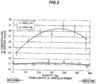
- FIG.2 is a graph showing the results of measuring the Cu concentration in outermost surface layers of electrical discharge machining electrode wires in Example and Comparative Example.
- the Cu concentration was measured at intervals of about 25 kg from the end portion in Example and at intervals of about 50 kg from the end portion in Comparative Example.
- the Cu concentration in the longitudinal direction of the electrode wire in Example had a variation range of 2.7 mass%, and the Cu concentration in the longitudinal direction of the electrode wire in Comparative Example had a variation range of 12 mass%.
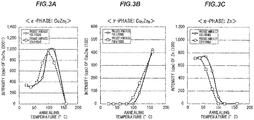
- FIGS.3A to 3C show the results of x-ray diffraction intensity measured on the electrical discharge machining electrode wires (core diameter: 0.20 mm) made at different annealing times and annealing temperatures, wherein FIG.3A is the result of measuring intensity of (0001) of the ⁇ -phase (CuZn 5 ) in the covering layer, FIG.3B is the result of measuring intensity of (332) of the ⁇ -phase (Cu 5 Zn 8 ) in the covering layer and FIG.3C is the result of measuring intensity of (100) of the ⁇ -phase (Zn) in the covering layer.
- a plot at 25°C is the measurement result of a non-annealed electrical discharge machining electrode wire.
- a zinc plating layer having a thickness of about 10 ⁇ m was formed on a brass wire (diameter: 1.2 mm) as the core 1.
- the core 1 plated with zinc was drawn to a diameter of 0.20 mm (to 1.7 ⁇ m of the plating layer), was then wound onto a bobbin (F 10 : spindle diameter of 100 mm), and was annealed in this state, thereby making 10 kg each of electrical discharge machining electrode wires.
- the annealing conditions were 40 to 160°C (40, 60, 80, 100, 120 or 160°C) for 3 hours or for 8 hours.
- the x-ray diffraction intensity of (0001) of the ⁇ -phase is more than twice the x-ray diffraction intensity of (332) of the ⁇ -phase when annealing time was 3 hours and also 8 hours.
- an x-ray diffraction intensity of (100) of the ⁇ phase (Zn) was 0 when annealed at a temperature of 100°C or more for 8 hours and when annealed at a temperature of 120°C or more for 3 hours ( FIG.3C ).
- the ⁇ -phase is a pure Zn phase and is likely to produce abrasion powder due to its softness, which accumulates as debris on a pass line of an electrical discharge machine. Therefore, the ⁇ -phase is preferably eliminated by heat treatment, and it is understood that this requires heat treatment at not less than 100°C.
Landscapes
- Chemical & Material Sciences (AREA)
- Engineering & Computer Science (AREA)
- Mechanical Engineering (AREA)
- Metallurgy (AREA)
- Organic Chemistry (AREA)
- Materials Engineering (AREA)
- Chemical Kinetics & Catalysis (AREA)
- Electrochemistry (AREA)
- Physics & Mathematics (AREA)
- Thermal Sciences (AREA)
- Crystallography & Structural Chemistry (AREA)
- Manufacturing & Machinery (AREA)
- Electrical Discharge Machining, Electrochemical Machining, And Combined Machining (AREA)
- Electroplating Methods And Accessories (AREA)
Applications Claiming Priority (1)
| Application Number | Priority Date | Filing Date | Title |
|---|---|---|---|
| PCT/JP2015/050277 WO2016110964A1 (ja) | 2015-01-07 | 2015-01-07 | 放電加工用電極線及びその製造方法 |
Publications (2)
| Publication Number | Publication Date |
|---|---|
| EP3100813A1 true EP3100813A1 (de) | 2016-12-07 |
| EP3100813A4 EP3100813A4 (de) | 2017-10-11 |
Family
ID=56355686
Family Applications (1)
| Application Number | Title | Priority Date | Filing Date |
|---|---|---|---|
| EP15876842.4A Withdrawn EP3100813A4 (de) | 2015-01-07 | 2015-01-07 | Funkenerosionsbearbeitungselektrodendraht und herstellungsverfahren dafür |
Country Status (5)
| Country | Link |
|---|---|
| US (1) | US10399167B2 (de) |
| EP (1) | EP3100813A4 (de) |
| JP (1) | JP6369546B2 (de) |
| KR (1) | KR20160113285A (de) |
| WO (1) | WO2016110964A1 (de) |
Cited By (1)
| Publication number | Priority date | Publication date | Assignee | Title |
|---|---|---|---|---|
| CN111673311A (zh) * | 2020-05-19 | 2020-09-18 | 西安理工大学 | Ta1-q235b中间层焊接用焊丝及方法与起弧位置 |
Families Citing this family (5)
| Publication number | Priority date | Publication date | Assignee | Title |
|---|---|---|---|---|
| JP6418507B2 (ja) * | 2014-11-07 | 2018-11-07 | 日立金属株式会社 | 放電加工用電極線の製造方法 |
| JP6369545B2 (ja) * | 2015-01-07 | 2018-08-08 | 日立金属株式会社 | 放電加工用電極線及びその製造方法 |
| JP6905106B1 (ja) | 2020-01-30 | 2021-07-21 | 株式会社ソディック | 熱処理炉、加熱装置、ワイヤ電極の製造方法および熱拡散処理方法 |
| JP7823530B2 (ja) * | 2022-09-09 | 2026-03-04 | 株式会社プロテリアル | ワイヤー放電加工用電極線 |
| KR102681672B1 (ko) * | 2024-01-29 | 2024-07-04 | 주식회사 이디엠지엠케이 | 전극선 인발 열처리 및 냉각 시스템 |
Family Cites Families (12)
| Publication number | Priority date | Publication date | Assignee | Title |
|---|---|---|---|---|
| DE2742008C2 (de) | 1977-09-17 | 1983-12-29 | Diehl GmbH & Co, 8500 Nürnberg | Verfahren zur Herstellung eines Messing-Werkstoffes mit Mikroduplex-Gefüge |
| JPS5924170B2 (ja) * | 1977-11-10 | 1984-06-07 | 秀夫 金子 | 放電加工用ワイヤ電極用合金 |
| US5762726A (en) | 1995-03-24 | 1998-06-09 | Berkenhoff Gmbh | Wire electrode and process for producing a wire electrode, particular for a spark erosion process |
| DE19510740A1 (de) | 1995-03-24 | 1996-10-02 | Berkenhoff Gmbh | Drahtelektrode sowie Verfahren zur Herstellung einer Drahtelektrode, insbesondere für das Funkenerodierverfahren |
| US5945010A (en) * | 1997-09-02 | 1999-08-31 | Composite Concepts Company, Inc. | Electrode wire for use in electric discharge machining and process for preparing same |
| JP2002126950A (ja) | 2000-10-23 | 2002-05-08 | Sumitomo Metal Mining Co Ltd | ワイヤ放電加工用電極線の製造方法 |
| FR2833875B1 (fr) | 2001-12-21 | 2004-07-02 | Thermocompact Sa | Fil pour electroerosion a grande vitesse d'usinage |
| KR100543847B1 (ko) * | 2005-04-01 | 2006-01-20 | 주식회사 엠에이씨티 | 방전가공용 전극선 및 그 제조 방법 |
| EP2005343B1 (de) * | 2005-12-01 | 2020-06-03 | Thermocompact | Edm-leitung |
| JP2008296298A (ja) | 2007-05-30 | 2008-12-11 | Oki Electric Cable Co Ltd | ワイヤ放電加工用電極線 |
| CN104191056B (zh) * | 2014-08-13 | 2016-06-29 | 宁波博威麦特莱科技有限公司 | 一种高精度锌基合金电极丝及其制备方法 |
| JP6418507B2 (ja) | 2014-11-07 | 2018-11-07 | 日立金属株式会社 | 放電加工用電極線の製造方法 |
-
2015
- 2015-01-07 KR KR1020167023769A patent/KR20160113285A/ko not_active Ceased
- 2015-01-07 US US15/122,081 patent/US10399167B2/en active Active
- 2015-01-07 WO PCT/JP2015/050277 patent/WO2016110964A1/ja not_active Ceased
- 2015-01-07 EP EP15876842.4A patent/EP3100813A4/de not_active Withdrawn
- 2015-01-07 JP JP2016534746A patent/JP6369546B2/ja active Active
Cited By (2)
| Publication number | Priority date | Publication date | Assignee | Title |
|---|---|---|---|---|
| CN111673311A (zh) * | 2020-05-19 | 2020-09-18 | 西安理工大学 | Ta1-q235b中间层焊接用焊丝及方法与起弧位置 |
| CN111673311B (zh) * | 2020-05-19 | 2022-02-25 | 西安理工大学 | Ta1-q235b中间层焊接用焊丝及制备方法 |
Also Published As
| Publication number | Publication date |
|---|---|
| KR20160113285A (ko) | 2016-09-28 |
| JP6369546B2 (ja) | 2018-08-08 |
| US20170014927A1 (en) | 2017-01-19 |
| US10399167B2 (en) | 2019-09-03 |
| JPWO2016110964A1 (ja) | 2017-10-12 |
| EP3100813A4 (de) | 2017-10-11 |
| WO2016110964A1 (ja) | 2016-07-14 |
Similar Documents
| Publication | Publication Date | Title |
|---|---|---|
| EP3100813A1 (de) | Funkenerosionsbearbeitungselektrodendraht und herstellungsverfahren dafür | |
| RU2516125C2 (ru) | Проволочный электрод для электроэрозионной резки | |
| EP3216548B1 (de) | Elektrodendraht für funkenerosionsbearbeitung und herstellungsverfahren dafür | |
| CN109952386B (zh) | 合金涂覆的edm丝 | |
| EP2644750A1 (de) | Elektrisch leitendes Material für Verbindungskomponente | |
| CN113811415B (zh) | 用于火花腐蚀切割的电极线及其制造方法 | |
| EP2784184A1 (de) | Elektrisch leitfähiges Material mit hoher Beständigkeit gegen Reibkorrosion für eine Verbindungskomponente | |
| JP2015170422A (ja) | 銅コイル材、銅平角線、被覆平角線、銅コイル材の製造方法、及び銅平角線の製造方法 | |
| US10384282B2 (en) | Electric discharge machining electrode wire and manufacturing method therefor | |
| KR102451451B1 (ko) | 와이어 방전 가공용 전극선 | |
| CN105283262B (zh) | 用于放电切割物体的电极丝 | |
| KR20200139662A (ko) | 도금 선봉 | |
| JP2024543089A (ja) | 電極ワイヤ及びその製造方法 | |
| TW202449183A (zh) | 銲線及其製造方法 | |
| DE10316612A1 (de) | Elektrolytisch beschichtetes Kaltband, vorzugsweise zur Verwendung für die Herstellung von Batteriehülsen sowie Verfahren zur Beschichtung derselben | |
| JP2024542236A (ja) | 電極ワイヤ及びその製造方法 | |
| HK40101520A (en) | Electric wires and cables for space applications |
Legal Events
| Date | Code | Title | Description |
|---|---|---|---|
| PUAI | Public reference made under article 153(3) epc to a published international application that has entered the european phase |
Free format text: ORIGINAL CODE: 0009012 |
|
| 17P | Request for examination filed |
Effective date: 20160830 |
|
| AK | Designated contracting states |
Kind code of ref document: A1 Designated state(s): AL AT BE BG CH CY CZ DE DK EE ES FI FR GB GR HR HU IE IS IT LI LT LU LV MC MK MT NL NO PL PT RO RS SE SI SK SM TR |
|
| AX | Request for extension of the european patent |
Extension state: BA ME |
|
| A4 | Supplementary search report drawn up and despatched |
Effective date: 20170907 |
|
| RIC1 | Information provided on ipc code assigned before grant |
Ipc: B23H 1/06 20060101ALI20170901BHEP Ipc: H01B 19/04 20060101ALI20170901BHEP Ipc: C22F 1/16 20060101ALI20170901BHEP Ipc: H01B 1/02 20060101ALI20170901BHEP Ipc: B23H 7/08 20060101ALI20170901BHEP Ipc: C25D 3/22 20060101ALI20170901BHEP Ipc: C22C 9/04 20060101AFI20170901BHEP Ipc: C25D 5/50 20060101ALI20170901BHEP Ipc: C22F 1/08 20060101ALI20170901BHEP Ipc: C22C 18/02 20060101ALI20170901BHEP |
|
| STAA | Information on the status of an ep patent application or granted ep patent |
Free format text: STATUS: THE APPLICATION HAS BEEN WITHDRAWN |
|
| 18W | Application withdrawn |
Effective date: 20180202 |