EP3100814B1 - Behälter mit schweissdrahtspule - Google Patents
Behälter mit schweissdrahtspule Download PDFInfo
- Publication number
- EP3100814B1 EP3100814B1 EP16176630.8A EP16176630A EP3100814B1 EP 3100814 B1 EP3100814 B1 EP 3100814B1 EP 16176630 A EP16176630 A EP 16176630A EP 3100814 B1 EP3100814 B1 EP 3100814B1
- Authority
- EP
- European Patent Office
- Prior art keywords
- container
- welding wire
- metal
- metal cage
- floor
- Prior art date
- Legal status (The legal status is an assumption and is not a legal conclusion. Google has not performed a legal analysis and makes no representation as to the accuracy of the status listed.)
- Active
Links
Images




Classifications
-
- B—PERFORMING OPERATIONS; TRANSPORTING
- B23—MACHINE TOOLS; METAL-WORKING NOT OTHERWISE PROVIDED FOR
- B23K—SOLDERING OR UNSOLDERING; WELDING; CLADDING OR PLATING BY SOLDERING OR WELDING; CUTTING BY APPLYING HEAT LOCALLY, e.g. FLAME CUTTING; WORKING BY LASER BEAM
- B23K9/00—Arc welding or cutting
- B23K9/32—Accessories
- B23K9/327—Means for transporting supplies
-
- B—PERFORMING OPERATIONS; TRANSPORTING
- B23—MACHINE TOOLS; METAL-WORKING NOT OTHERWISE PROVIDED FOR
- B23K—SOLDERING OR UNSOLDERING; WELDING; CLADDING OR PLATING BY SOLDERING OR WELDING; CUTTING BY APPLYING HEAT LOCALLY, e.g. FLAME CUTTING; WORKING BY LASER BEAM
- B23K35/00—Rods, electrodes, materials, or media, for use in soldering, welding, or cutting
- B23K35/02—Rods, electrodes, materials, or media, for use in soldering, welding, or cutting characterised by mechanical features, e.g. shape
-
- B—PERFORMING OPERATIONS; TRANSPORTING
- B23—MACHINE TOOLS; METAL-WORKING NOT OTHERWISE PROVIDED FOR
- B23K—SOLDERING OR UNSOLDERING; WELDING; CLADDING OR PLATING BY SOLDERING OR WELDING; CUTTING BY APPLYING HEAT LOCALLY, e.g. FLAME CUTTING; WORKING BY LASER BEAM
- B23K35/00—Rods, electrodes, materials, or media, for use in soldering, welding, or cutting
- B23K35/02—Rods, electrodes, materials, or media, for use in soldering, welding, or cutting characterised by mechanical features, e.g. shape
- B23K35/0255—Rods, electrodes, materials, or media, for use in soldering, welding, or cutting characterised by mechanical features, e.g. shape for use in welding
- B23K35/0261—Rods, electrodes or wires
-
- B—PERFORMING OPERATIONS; TRANSPORTING
- B23—MACHINE TOOLS; METAL-WORKING NOT OTHERWISE PROVIDED FOR
- B23K—SOLDERING OR UNSOLDERING; WELDING; CLADDING OR PLATING BY SOLDERING OR WELDING; CUTTING BY APPLYING HEAT LOCALLY, e.g. FLAME CUTTING; WORKING BY LASER BEAM
- B23K9/00—Arc welding or cutting
- B23K9/12—Automatic feeding or moving of electrodes or work for spot or seam welding or cutting
- B23K9/133—Means for feeding electrodes, e.g. drums, rolls, motors
- B23K9/1333—Dereeling means
-
- B—PERFORMING OPERATIONS; TRANSPORTING
- B23—MACHINE TOOLS; METAL-WORKING NOT OTHERWISE PROVIDED FOR
- B23K—SOLDERING OR UNSOLDERING; WELDING; CLADDING OR PLATING BY SOLDERING OR WELDING; CUTTING BY APPLYING HEAT LOCALLY, e.g. FLAME CUTTING; WORKING BY LASER BEAM
- B23K9/00—Arc welding or cutting
- B23K9/18—Submerged-arc welding
- B23K9/186—Submerged-arc welding making use of a consumable electrodes
-
- B—PERFORMING OPERATIONS; TRANSPORTING
- B65—CONVEYING; PACKING; STORING; HANDLING THIN OR FILAMENTARY MATERIAL
- B65D—CONTAINERS FOR STORAGE OR TRANSPORT OF ARTICLES OR MATERIALS, e.g. BAGS, BARRELS, BOTTLES, BOXES, CANS, CARTONS, CRATES, DRUMS, JARS, TANKS, HOPPERS, FORWARDING CONTAINERS; ACCESSORIES, CLOSURES, OR FITTINGS THEREFOR; PACKAGING ELEMENTS; PACKAGES
- B65D85/00—Containers, packaging elements or packages, specially adapted for particular articles or materials
- B65D85/02—Containers, packaging elements or packages, specially adapted for particular articles or materials for annular articles
- B65D85/04—Containers, packaging elements or packages, specially adapted for particular articles or materials for annular articles for coils of wire, rope or hose
-
- B—PERFORMING OPERATIONS; TRANSPORTING
- B65—CONVEYING; PACKING; STORING; HANDLING THIN OR FILAMENTARY MATERIAL
- B65H—HANDLING THIN OR FILAMENTARY MATERIAL, e.g. SHEETS, WEBS, CABLES
- B65H49/00—Unwinding or paying-out filamentary material; Supporting, storing or transporting packages from which filamentary material is to be withdrawn or paid-out
- B65H49/02—Methods or apparatus in which packages do not rotate
- B65H49/04—Package-supporting devices
- B65H49/06—Package-supporting devices for a single operative package
- B65H49/08—Package-supporting devices for a single operative package enclosing the package
-
- B—PERFORMING OPERATIONS; TRANSPORTING
- B65—CONVEYING; PACKING; STORING; HANDLING THIN OR FILAMENTARY MATERIAL
- B65H—HANDLING THIN OR FILAMENTARY MATERIAL, e.g. SHEETS, WEBS, CABLES
- B65H57/00—Guides for filamentary materials; Supports therefor
- B65H57/18—Guides for filamentary materials; Supports therefor mounted to facilitate unwinding of material from packages
-
- B—PERFORMING OPERATIONS; TRANSPORTING
- B65—CONVEYING; PACKING; STORING; HANDLING THIN OR FILAMENTARY MATERIAL
- B65H—HANDLING THIN OR FILAMENTARY MATERIAL, e.g. SHEETS, WEBS, CABLES
- B65H2701/00—Handled material; Storage means
- B65H2701/30—Handled filamentary material
- B65H2701/36—Wires
Definitions
- the invention relates to a container for a welding wire coil, in particular for a welding wire coil consisting of a length of welding wire with a diameter of 2.00 mm or more.
- Welding wire with these diameters can be used for submerged arc welding.
- a problem with these welding wires is that they have to be introduced into the welding equipment (feeder, wire guiding system, welding torch, etc.).
- the problem is that in particular in the wire guiding system, the welding wire is subjected to bends.
- Wire having a diameter of 2.00 mm or more (diameters can go up to 6.00 mm and in some cases even beyond) can however hardly be fed through the guiding hoses, etc.
- wire pushing systems There were attempts to use wire pushing systems to solve this problem, but without convincing success.
- JP 2005 169499 A describes a container for welding wire according to the preamble of claim 1 and having a supporting structure made from metal.
- the container has an octagonal cross section and is constituted of a lower and an upper ring, which are connected by vertically extending metal bars.
- the container may also have intermediate rings for stabilization.
- the invention proposes a container for accommodating an amount of welding wire, having a metal cage with a floor portion and a side portion extending from the floor portion, and having a cardboard wall associated to the side portion of the metal cage, wherein the metal cage has an octagonal cross section and the cardboard wall consists of eight segments.
- This container is based on the idea of assigning the different objects of the container to different elements.
- the metal cage is provided for achieving the mechanical stability which is required for receiving the welding wire coil and holding it during transportation and handling.
- the cardboard wall is provided for protecting the welding wire coil against contamination and dirt.
- the components of the metal cage are simply welded to each other.
- the floor portion can consist of four flat metal bars which are arranged pairwise perpendicularly with respect to each other, and the side portion of the metal cage can consist of eight metal tubes which are welded to the ends of the four metal bars.
- the cage can be formed very quickly.
- a reinforcement ring can be provided at an end of the side portion which is opposite the floor portion.
- the reinforcement ring preferably is made from a metal strip which is welded to the tubes.
- the cardboard wall is preferably formed in a single piece which extends around the side portion of the metal cage. This allows to simply slip the cardboard wall over the metal cage during assembly.
- a cardboard floor is associated to the floor portion of the metal cage.
- the cardboard floor can be connected to the floor portion of the metal cage by means of supporting feet which are arranged underneath the container and which clamp the cardboard floor to the metal cage.
- the supporting feet can be attached by means of bolts which extend from the interior of the container, and nuts which are accessible at an outer surface of the supporting feet. This allows to mount the supporting feet at the container in a simple manner, and also to detach the feet therefrom.
- the supporting feet can be made from wood. Preferably, they are arranged at the container such that a forklift can be used for handling the container.
- the dome is detachably connected to the metal frame.
- the dome can have a couple of legs which are inserted into the metal tubes forming the side portion of the metal cage. If necessary, locking pins can be used.
- a protective plastic bag is arranged between the side portion of the metal cage and the cardboard wall.
- the plastic bag prevents moisture from entering into the interior of the container.
- the container is in particular suited for accommodating a welding wire coil made from welding wire having a diameter of more than 2.00 mm, preferably of 4.00 to 6.00 mm. Welding wire with this diameter, which is particularly suitable for sub-arc welding, requires a particularly strong container.
- the metal cage of the container according to the invention provides the required strength due to the metal cage which is able to receive the forces exerted by the welding wire coil.
- the welding wire coil placed in the container has an initial starting portion, the diameter of which is reduced as compared to the diameter of the remainder of the welding wire of the welding wire coil.
- the starting portion with reduced diameter facilitates insertion of the welding wire into a liner guiding the welding wire from the welding wire coil towards a welding torch.
- the starting portion can have a length of 0.5 to 4 m, depending on the particular application. In some cases, it is sufficient to have just a short starting portion which is followed by welding wire with its nominal diameter. For other applications, insertion of the welding wire is greatly facilitated if the starting portion can be completely fed into the welding system until it exits at the welding torch and can be pulled through the welding system. Once the welding wire with the nominal diameter arrives at the welding torch, the starting portion is cut off.
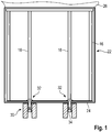
- a container for accommodating a welding wire coil is shown in Figures 1 to 4 .
- the container consists of three elements: A metal cage 10, a cardboard cover 20 and feet 30.
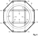
- the metal cage 10 consists of a floor portion formed by four metal bars 12 arranged so as to form a grid (please see in particular Figure 2 ).
- the metal bars 12 are arranged such that their outer ends define the corners of an octagonal.
- a bolt hole 14 is provided at each junction, which extends through both superimposed metal bars.
- Metal cage 10 further comprises a side portion or side structure formed from eight metal tubes 16.
- the metal tubes 16 are connected with one of their ends to a respective end of metal bars 12 so that they extend perpendicularly therefrom upwardly.
- metal cage 10 comprises a reinforcement ring 18 which circumscribes the structure formed by the metal tubes 16 at their end which is opposite to the floor structure formed by metal bars 12.
- a metal frame is thereby formed which comprises a bottom formed by metal bars 12, a side structure formed by metal tubes 16 and an upper opening circumscribed by reinforcement ring 18.
- the accommodation space within the metal cage has an octagonal cross section. All components can be welded to each other in order to combine reduced expenditure for manufacturing with high mechanical strength.
- Cardboard cover 20 comprises of a cardboard wall 22 which covers the outer circumference of the side structure of the metal cage 10. Accordingly, cardboard wall 22 consists of eight segments each extending from one metal tube 16 to the adjacent one. Nevertheless, the entire cardboard wall 22 can be formed in a single, sleeve-like piece. Further, cardboard cover 20 comprises a cardboard floor 24 which is arranged underneath the floor portion of metal cage 10 and closes the underside of the container. Cardboard floor 24 is preferably provided separate from cardboard wall 22 and has a rim portion which outwardly circumscribes the lower edge of cardboard wall 22.
- a protective plastic bag 26 is provided which extends between metal cage 10 and the cardboard wall 22 and cardboard floor 24.
- Protective plastic bag 26 ensures that moisture cannot enter into the interior of the container.
- Cardboard wall 22 in combination with cardboard floor 24 provides a mechanical seal against dirt and contamination.
- wooden blocks 30 are provided which serve as supporting feet for the container. Wooden blocks 30 are connected to metal cage 10 by means of fastening bolts 32 which extends through bolt holes 14. The wooden blocks 30 are firmly attached to the metal cage by threading nuts 34 onto fastening bolts 32. The length of the fastening bolts is significantly shorter than the height of wooden blocks 30 so that nuts 34 are accommodated recessed within the wooden blocks. This ensures an electrical insulation between the metal cage and a floor on which the container is placed.
- the wooden blocks can either be provided in the form of two long bars extending in parallel underneath the container, or in the form of four short sections.
- the first alternative provides more stability, but result in only two directions from which a forklift can be introduced.
- the second alternative results in a slightly reduced stability but allows introducing a forklift from four directions.
- the container is intended to receive a large amount of welding wire 40 stored in the container in the form of a coil formed from a large number of welding wire loops.
- the coil formed from welding wire 40 is arranged such that it sits on the floor portion of the metal cage, namely on metal bars 12, and abuts with its outer circumferential surface at the eight metal tubes 16.
- a retainer 42 is preferably arranged on top of the welding wire coil.
- the retainer (please see in particular Figure 4 ) has a generally octagonal shape, with recesses being provided in each corner so as to allow the metal tubes 16 to pass through.
- Retainer 42 is generally plate-like with an interior opening 44 which is circular and has a diameter which is slightly smaller than the inner diameter of the coil formed from welding wire 40. Retainer 42 prevents that welding wire loops prematurely lift from the welding wire coil.
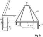
- a dome 50 can be used with the container, which has an upper opening 52 through which the welding wire can be withdrawn.
- Cage 50 is preferably a metal cage having a couple of legs 54 which are arranged and dimensioned so as to fit into the inner space of metal tubes 16 forming the corner reinforcements of the container. This allows to securely mount dome 50 to the container. If necessary, additional locking elements such as a pin 56 (please see Figure 4 ) can be used which extends through a bore both in the metal tube 16 of the metal cage and the leg 54 of dome 50. This prevents that dome 50 unintentionally becomes separated from the container during use.
- the container is particularly suitable for receiving welding wire with a comparatively large diameter, in particular significantly exceeding a diameter of 2.00 mm.
- the metal cage is of sufficient strength to receive and hold welding wire having a diameter of 4.00 mm and even 6.00 mm and above. This type of welding wire is particularly suitable for sub-arc welding.
- the welding wire 40 of the coil has an initial insertion portion 46 whose diameter D R is reduced as compared to the nominal diameter D N of the remainder of the welding wire 40.
- This initial insertion portion 46 can have a diameter D R of for example 2.00 mm while the nominal diameter D N of the welding wire 40 is 4.00 or 6.00 mm.
- the insertion portion can be formed by gradually reducing the diameter in a transition portion 48 from the nominal diameter D N to the reduced diameter D R , for example by using a drawing die, and to integrally form the insertion portion with the reduced diameter.
- the welding wire can be provided with the transition portion 48, and a separate portion of welding wire with smaller diameter D N can be butt-welded to the end of the transition portion 48 of the welding wire 40.
- the insertion portion of the welding wire can be easily inserted into a liner so as to smoothly follow its curvatures when being pushed though the liner.
- the initial insertion portion 46 can be cut off, and welding can start.
- a particular advantage of the container is that it can be assembled and disassembled in a very simple manner.
- the cardboard cover 20 is held at the metal cage 10 by means of the supporting feet 30 which are mounted by a few bolts.
- a customer can dispose of the container in a convenient way. By unscrewing the nuts 34 from the bolts 32, the wooden blocks 30 can be separated from the container. This also results in the cardboard cover 20 becoming detached from the metal cage 10. Metal cage 10 can be sold as scrap metal. Cardboard wall 20 can be stored in a flat condition and finally recycled. The wooden blocks can be discarded. Accordingly, the customer does not have the problem what to do with an emptied container requiring much space.
Landscapes
- Engineering & Computer Science (AREA)
- Mechanical Engineering (AREA)
- Physics & Mathematics (AREA)
- Plasma & Fusion (AREA)
- Packaging Of Annular Or Rod-Shaped Articles, Wearing Apparel, Cassettes, Or The Like (AREA)
Claims (10)
- Behälter für die Aufnahme einer Menge Schweißdraht (40), der einen Metallkäfig (10) mit einem Bodenabschnitt und einem sich ausgehend von dem Bodenabschnitt erstreckenden Seitenabschnitt und eine Wand (22) aus Pappe aufweist, die dem Seitenabschnitt des Metallkäfigs (10) zugeordnet ist, wobei der Metallkäfig (10) einen achteckigen Querschnitt hat, dadurch gekennzeichnet, dass die Wand (22) aus Pappe aus acht Segmenten besteht.
- Behälter nach Anspruch 1, wobei der Bodenabschnitt aus flachen Metallstäben (12) besteht.
- Behälter nach Anspruch 2, wobei der Bodenabschnitt aus vier Stäben (12) gebildet ist, die paarweise senkrecht zueinander angeordnet sind, wobei die äußeren Enden der Stäbe (12) acht Ecken des Behälters definieren.
- Behälter nach einem der vorhergehenden Ansprüche, wobei der Seitenabschnitt aus Metallrohren (16) besteht.
- Behälter nach einem der vorhergehenden Ansprüche, wobei an einem Ende des Seitenabschnitts, das zum Bodenabschnitt entgegengesetzt ist, ein Verstärkungsring (18) vorgesehen ist.
- Behälter nach einem der vorhergehenden Ansprüche, wobei die Wand (22) aus Pappe aus einem einzigen Stück gebildet ist, das sich um den Seitenabschnitt des Metallkäfigs (10) herum erstreckt.
- Behälter nach einem der vorhergehenden Ansprüche, wobei Stützfüße (30) am Bodenabschnitt des Metallkäfigs (10) befestigt sind.
- Behälter nach Anspruch 7, wobei die Stützfüße (30) mittels Schrauben (32), die sich vom Inneren des Behälters erstrecken, und mittels Muttern (34), die an einer Außenfläche der Stützfüße (30) zugänglich sind, befestigt sind.
- Behälter nach Anspruch 8, wobei die Stützfüße (30) aus Holz bestehen.
- Behälter nach einem der vorhergehenden Ansprüche, der ferner eine Haube (50) aufweist, die an dem Ende des Seitenabschnitts des Metallkäfigs (10) angeordnet ist, das zum Bodenabschnitt entgegengesetzt ist.
Priority Applications (4)
| Application Number | Priority Date | Filing Date | Title |
|---|---|---|---|
| EP16176630.8A EP3100814B1 (de) | 2011-01-13 | 2011-01-13 | Behälter mit schweissdrahtspule |
| DK16176630.8T DK3100814T3 (da) | 2011-01-13 | 2011-01-13 | Beholder med svejsetrådsspole |
| ES16176630T ES2768972T3 (es) | 2011-01-13 | 2011-01-13 | Recipiente con bobina de alambre de soldadura |
| PL16176630T PL3100814T3 (pl) | 2011-01-13 | 2011-01-13 | Pojemnik na zwój drutu spawalniczego |
Applications Claiming Priority (2)
| Application Number | Priority Date | Filing Date | Title |
|---|---|---|---|
| EP16176630.8A EP3100814B1 (de) | 2011-01-13 | 2011-01-13 | Behälter mit schweissdrahtspule |
| EP11000236A EP2476501A1 (de) | 2011-01-13 | 2011-01-13 | Schweißdrahtring und Behälter mit einem Schweißdrahtring |
Related Parent Applications (1)
| Application Number | Title | Priority Date | Filing Date |
|---|---|---|---|
| EP11000236A Division EP2476501A1 (de) | 2011-01-13 | 2011-01-13 | Schweißdrahtring und Behälter mit einem Schweißdrahtring |
Publications (2)
| Publication Number | Publication Date |
|---|---|
| EP3100814A1 EP3100814A1 (de) | 2016-12-07 |
| EP3100814B1 true EP3100814B1 (de) | 2019-12-25 |
Family
ID=44117013
Family Applications (2)
| Application Number | Title | Priority Date | Filing Date |
|---|---|---|---|
| EP11000236A Withdrawn EP2476501A1 (de) | 2011-01-13 | 2011-01-13 | Schweißdrahtring und Behälter mit einem Schweißdrahtring |
| EP16176630.8A Active EP3100814B1 (de) | 2011-01-13 | 2011-01-13 | Behälter mit schweissdrahtspule |
Family Applications Before (1)
| Application Number | Title | Priority Date | Filing Date |
|---|---|---|---|
| EP11000236A Withdrawn EP2476501A1 (de) | 2011-01-13 | 2011-01-13 | Schweißdrahtring und Behälter mit einem Schweißdrahtring |
Country Status (4)
| Country | Link |
|---|---|
| EP (2) | EP2476501A1 (de) |
| DK (1) | DK3100814T3 (de) |
| ES (1) | ES2768972T3 (de) |
| PL (1) | PL3100814T3 (de) |
Families Citing this family (3)
| Publication number | Priority date | Publication date | Assignee | Title |
|---|---|---|---|---|
| EP2484476A1 (de) * | 2011-02-04 | 2012-08-08 | SIDERGAS SpA | Schweißdrahtring und Behälter mit einem Schweißdrahtring |
| US10703557B2 (en) * | 2017-06-07 | 2020-07-07 | Illinois Tool Works Inc. | Drums for transporting and feeding wire |
| US20230011011A1 (en) * | 2021-07-09 | 2023-01-12 | Sidergas Spa | Wire container |
Citations (1)
| Publication number | Priority date | Publication date | Assignee | Title |
|---|---|---|---|---|
| WO1998052844A1 (en) * | 1997-05-20 | 1998-11-26 | Esab Ab | Container for packaging and unwinding a coil of welding wire |
Family Cites Families (8)
| Publication number | Priority date | Publication date | Assignee | Title |
|---|---|---|---|---|
| US3119042A (en) * | 1961-03-14 | 1964-01-21 | Chemetron Corp | Apparatus and method for feeding fabricated welding wire |
| JPS5435842A (en) * | 1977-08-26 | 1979-03-16 | Nippon Steel Welding Prod Eng | Method for connecting wires in automatic welder |
| JPS5554295A (en) * | 1978-10-13 | 1980-04-21 | Nippon Steel Weld Prod & Eng Co Ltd | Connecting method of wire for automatic welding |
| JPH07247058A (ja) * | 1994-03-08 | 1995-09-26 | Kobe Steel Ltd | 溶接用ワイヤの装填物及び溶接ワイヤ用のペイル容器 |
| KR100560824B1 (ko) * | 2003-12-12 | 2006-03-13 | 고려용접봉 주식회사 | 재활용이 가능한 용접 와이어용 페일팩 |
| US8245846B2 (en) * | 2006-02-02 | 2012-08-21 | Lincoln Global, Inc. | Box for welding wire |
| EP2256064A1 (de) * | 2009-05-27 | 2010-12-01 | ISAF S.p.A. | Behälter für Schweißdraht mit verlängerten Elementen zum Halten der Drahtspule |
| US20110042355A1 (en) * | 2009-08-21 | 2011-02-24 | Carlo Gelmetti | Feeding system for a welding wire for a submerged welding process |
-
2011
- 2011-01-13 EP EP11000236A patent/EP2476501A1/de not_active Withdrawn
- 2011-01-13 ES ES16176630T patent/ES2768972T3/es active Active
- 2011-01-13 PL PL16176630T patent/PL3100814T3/pl unknown
- 2011-01-13 EP EP16176630.8A patent/EP3100814B1/de active Active
- 2011-01-13 DK DK16176630.8T patent/DK3100814T3/da active
Patent Citations (1)
| Publication number | Priority date | Publication date | Assignee | Title |
|---|---|---|---|---|
| WO1998052844A1 (en) * | 1997-05-20 | 1998-11-26 | Esab Ab | Container for packaging and unwinding a coil of welding wire |
Also Published As
| Publication number | Publication date |
|---|---|
| DK3100814T3 (da) | 2020-03-30 |
| PL3100814T3 (pl) | 2020-06-29 |
| EP2476501A1 (de) | 2012-07-18 |
| ES2768972T3 (es) | 2020-06-24 |
| EP3100814A1 (de) | 2016-12-07 |
Similar Documents
| Publication | Publication Date | Title |
|---|---|---|
| US8127923B2 (en) | Container for welding wire | |
| EP2484476A1 (de) | Schweißdrahtring und Behälter mit einem Schweißdrahtring | |
| EP4124586B1 (de) | Transportbehälter für eine elektrofahrzeugbatterie | |
| JP6474668B2 (ja) | ホイール運搬ユニット | |
| US10538360B2 (en) | Nestable pallet with runners | |
| KR100564115B1 (ko) | 개량 용접 와이어 드럼 및 이를 위한 단위형 패키지 | |
| JPH08509193A (ja) | パレットコンテナ | |
| EP3100814A1 (de) | Behälter mit schweissdrahtspule | |
| HUP0302662A2 (hu) | Palettatartály | |
| KR20180002513U (ko) | 코어 와이어의 저장 및 수송 콘테이너 | |
| EP2999638B1 (de) | Transportbehälter | |
| KR100661338B1 (ko) | 조립식 알루미늄 팔레트 | |
| HU210624B (en) | Plastic pallet | |
| JP2014526022A (ja) | 管端部用の蓋部材 | |
| JP2017001748A (ja) | 積層可能なパレットコンテナ | |
| US10287089B2 (en) | Drum for storage and transportation of articles and materials | |
| US10532854B2 (en) | Drum stacking assembly | |
| KR20090015960A (ko) | 물건을 비축하여 이동시키기 위한 팔레트 | |
| EP3309097B1 (de) | Schweissdrahtbehälter | |
| KR20160100763A (ko) | 롤 제품용 운반 및 포장장치 및 이를 이용한 롤 제품용 파렛트 | |
| CN1989045A (zh) | 合成树脂制货盘 | |
| TWI634053B (zh) | 連接器組件 | |
| JP4237240B1 (ja) | 搬送容器 | |
| KR20080054688A (ko) | 용접 와이어용 페일팩 | |
| KR100811158B1 (ko) | 절곡된 금속부재의 적재 및 운반용 파렛트 |
Legal Events
| Date | Code | Title | Description |
|---|---|---|---|
| PUAI | Public reference made under article 153(3) epc to a published international application that has entered the european phase |
Free format text: ORIGINAL CODE: 0009012 |
|
| STAA | Information on the status of an ep patent application or granted ep patent |
Free format text: STATUS: THE APPLICATION HAS BEEN PUBLISHED |
|
| AC | Divisional application: reference to earlier application |
Ref document number: 2476501 Country of ref document: EP Kind code of ref document: P |
|
| AK | Designated contracting states |
Kind code of ref document: A1 Designated state(s): AL AT BE BG CH CY CZ DE DK EE ES FI FR GB GR HR HU IE IS IT LI LT LU LV MC MK MT NL NO PL PT RO RS SE SI SK SM TR |
|
| STAA | Information on the status of an ep patent application or granted ep patent |
Free format text: STATUS: REQUEST FOR EXAMINATION WAS MADE |
|
| 17P | Request for examination filed |
Effective date: 20170322 |
|
| RBV | Designated contracting states (corrected) |
Designated state(s): AL AT BE BG CH CY CZ DE DK EE ES FI FR GB GR HR HU IE IS IT LI LT LU LV MC MK MT NL NO PL PT RO RS SE SI SK SM TR |
|
| RIC1 | Information provided on ipc code assigned before grant |
Ipc: B65H 49/38 20060101ALI20190521BHEP Ipc: B65H 57/18 20060101ALI20190521BHEP Ipc: B65H 49/08 20060101ALI20190521BHEP Ipc: B23K 9/32 20060101AFI20190521BHEP Ipc: B23K 35/02 20060101ALI20190521BHEP Ipc: B23K 9/18 20060101ALI20190521BHEP Ipc: B65D 85/04 20060101ALI20190521BHEP Ipc: B23K 9/133 20060101ALI20190521BHEP |
|
| GRAP | Despatch of communication of intention to grant a patent |
Free format text: ORIGINAL CODE: EPIDOSNIGR1 |
|
| STAA | Information on the status of an ep patent application or granted ep patent |
Free format text: STATUS: GRANT OF PATENT IS INTENDED |
|
| INTG | Intention to grant announced |
Effective date: 20190724 |
|
| GRAS | Grant fee paid |
Free format text: ORIGINAL CODE: EPIDOSNIGR3 |
|
| GRAA | (expected) grant |
Free format text: ORIGINAL CODE: 0009210 |
|
| STAA | Information on the status of an ep patent application or granted ep patent |
Free format text: STATUS: THE PATENT HAS BEEN GRANTED |
|
| AC | Divisional application: reference to earlier application |
Ref document number: 2476501 Country of ref document: EP Kind code of ref document: P |
|
| AK | Designated contracting states |
Kind code of ref document: B1 Designated state(s): AL AT BE BG CH CY CZ DE DK EE ES FI FR GB GR HR HU IE IS IT LI LT LU LV MC MK MT NL NO PL PT RO RS SE SI SK SM TR |
|
| REG | Reference to a national code |
Ref country code: GB Ref legal event code: FG4D |
|
| REG | Reference to a national code |
Ref country code: CH Ref legal event code: EP |
|
| REG | Reference to a national code |
Ref country code: DE Ref legal event code: R096 Ref document number: 602011064304 Country of ref document: DE |
|
| REG | Reference to a national code |
Ref country code: AT Ref legal event code: REF Ref document number: 1216625 Country of ref document: AT Kind code of ref document: T Effective date: 20200115 |
|
| REG | Reference to a national code |
Ref country code: IE Ref legal event code: FG4D |
|
| REG | Reference to a national code |
Ref country code: CH Ref legal event code: NV Representative=s name: BUGNION S.A., CH |
|
| REG | Reference to a national code |
Ref country code: SE Ref legal event code: TRGR |
|
| REG | Reference to a national code |
Ref country code: DK Ref legal event code: T3 Effective date: 20200326 |
|
| PG25 | Lapsed in a contracting state [announced via postgrant information from national office to epo] |
Ref country code: BG Free format text: LAPSE BECAUSE OF FAILURE TO SUBMIT A TRANSLATION OF THE DESCRIPTION OR TO PAY THE FEE WITHIN THE PRESCRIBED TIME-LIMIT Effective date: 20200325 Ref country code: GR Free format text: LAPSE BECAUSE OF FAILURE TO SUBMIT A TRANSLATION OF THE DESCRIPTION OR TO PAY THE FEE WITHIN THE PRESCRIBED TIME-LIMIT Effective date: 20200326 Ref country code: LT Free format text: LAPSE BECAUSE OF FAILURE TO SUBMIT A TRANSLATION OF THE DESCRIPTION OR TO PAY THE FEE WITHIN THE PRESCRIBED TIME-LIMIT Effective date: 20191225 Ref country code: FI Free format text: LAPSE BECAUSE OF FAILURE TO SUBMIT A TRANSLATION OF THE DESCRIPTION OR TO PAY THE FEE WITHIN THE PRESCRIBED TIME-LIMIT Effective date: 20191225 Ref country code: LV Free format text: LAPSE BECAUSE OF FAILURE TO SUBMIT A TRANSLATION OF THE DESCRIPTION OR TO PAY THE FEE WITHIN THE PRESCRIBED TIME-LIMIT Effective date: 20191225 Ref country code: NO Free format text: LAPSE BECAUSE OF FAILURE TO SUBMIT A TRANSLATION OF THE DESCRIPTION OR TO PAY THE FEE WITHIN THE PRESCRIBED TIME-LIMIT Effective date: 20200325 |
|
| REG | Reference to a national code |
Ref country code: SK Ref legal event code: T3 Ref document number: E 33486 Country of ref document: SK |
|
| REG | Reference to a national code |
Ref country code: NL Ref legal event code: FP |
|
| REG | Reference to a national code |
Ref country code: LT Ref legal event code: MG4D |
|
| PG25 | Lapsed in a contracting state [announced via postgrant information from national office to epo] |
Ref country code: RS Free format text: LAPSE BECAUSE OF FAILURE TO SUBMIT A TRANSLATION OF THE DESCRIPTION OR TO PAY THE FEE WITHIN THE PRESCRIBED TIME-LIMIT Effective date: 20191225 Ref country code: HR Free format text: LAPSE BECAUSE OF FAILURE TO SUBMIT A TRANSLATION OF THE DESCRIPTION OR TO PAY THE FEE WITHIN THE PRESCRIBED TIME-LIMIT Effective date: 20191225 |
|
| REG | Reference to a national code |
Ref country code: ES Ref legal event code: FG2A Ref document number: 2768972 Country of ref document: ES Kind code of ref document: T3 Effective date: 20200624 |
|
| PG25 | Lapsed in a contracting state [announced via postgrant information from national office to epo] |
Ref country code: AL Free format text: LAPSE BECAUSE OF FAILURE TO SUBMIT A TRANSLATION OF THE DESCRIPTION OR TO PAY THE FEE WITHIN THE PRESCRIBED TIME-LIMIT Effective date: 20191225 |
|
| PG25 | Lapsed in a contracting state [announced via postgrant information from national office to epo] |
Ref country code: EE Free format text: LAPSE BECAUSE OF FAILURE TO SUBMIT A TRANSLATION OF THE DESCRIPTION OR TO PAY THE FEE WITHIN THE PRESCRIBED TIME-LIMIT Effective date: 20191225 Ref country code: RO Free format text: LAPSE BECAUSE OF FAILURE TO SUBMIT A TRANSLATION OF THE DESCRIPTION OR TO PAY THE FEE WITHIN THE PRESCRIBED TIME-LIMIT Effective date: 20191225 Ref country code: PT Free format text: LAPSE BECAUSE OF FAILURE TO SUBMIT A TRANSLATION OF THE DESCRIPTION OR TO PAY THE FEE WITHIN THE PRESCRIBED TIME-LIMIT Effective date: 20200520 |
|
| PG25 | Lapsed in a contracting state [announced via postgrant information from national office to epo] |
Ref country code: SM Free format text: LAPSE BECAUSE OF FAILURE TO SUBMIT A TRANSLATION OF THE DESCRIPTION OR TO PAY THE FEE WITHIN THE PRESCRIBED TIME-LIMIT Effective date: 20191225 Ref country code: IS Free format text: LAPSE BECAUSE OF FAILURE TO SUBMIT A TRANSLATION OF THE DESCRIPTION OR TO PAY THE FEE WITHIN THE PRESCRIBED TIME-LIMIT Effective date: 20200425 |
|
| REG | Reference to a national code |
Ref country code: DE Ref legal event code: R097 Ref document number: 602011064304 Country of ref document: DE |
|
| PG25 | Lapsed in a contracting state [announced via postgrant information from national office to epo] |
Ref country code: MC Free format text: LAPSE BECAUSE OF FAILURE TO SUBMIT A TRANSLATION OF THE DESCRIPTION OR TO PAY THE FEE WITHIN THE PRESCRIBED TIME-LIMIT Effective date: 20191225 |
|
| PG25 | Lapsed in a contracting state [announced via postgrant information from national office to epo] |
Ref country code: LU Free format text: LAPSE BECAUSE OF NON-PAYMENT OF DUE FEES Effective date: 20200113 |
|
| PLBE | No opposition filed within time limit |
Free format text: ORIGINAL CODE: 0009261 |
|
| STAA | Information on the status of an ep patent application or granted ep patent |
Free format text: STATUS: NO OPPOSITION FILED WITHIN TIME LIMIT |
|
| PG25 | Lapsed in a contracting state [announced via postgrant information from national office to epo] |
Ref country code: SI Free format text: LAPSE BECAUSE OF FAILURE TO SUBMIT A TRANSLATION OF THE DESCRIPTION OR TO PAY THE FEE WITHIN THE PRESCRIBED TIME-LIMIT Effective date: 20191225 |
|
| 26N | No opposition filed |
Effective date: 20200928 |
|
| PG25 | Lapsed in a contracting state [announced via postgrant information from national office to epo] |
Ref country code: IE Free format text: LAPSE BECAUSE OF NON-PAYMENT OF DUE FEES Effective date: 20200113 |
|
| PG25 | Lapsed in a contracting state [announced via postgrant information from national office to epo] |
Ref country code: TR Free format text: LAPSE BECAUSE OF FAILURE TO SUBMIT A TRANSLATION OF THE DESCRIPTION OR TO PAY THE FEE WITHIN THE PRESCRIBED TIME-LIMIT Effective date: 20191225 Ref country code: MT Free format text: LAPSE BECAUSE OF FAILURE TO SUBMIT A TRANSLATION OF THE DESCRIPTION OR TO PAY THE FEE WITHIN THE PRESCRIBED TIME-LIMIT Effective date: 20191225 Ref country code: CY Free format text: LAPSE BECAUSE OF FAILURE TO SUBMIT A TRANSLATION OF THE DESCRIPTION OR TO PAY THE FEE WITHIN THE PRESCRIBED TIME-LIMIT Effective date: 20191225 |
|
| REG | Reference to a national code |
Ref country code: AT Ref legal event code: UEP Ref document number: 1216625 Country of ref document: AT Kind code of ref document: T Effective date: 20191225 |
|
| PG25 | Lapsed in a contracting state [announced via postgrant information from national office to epo] |
Ref country code: MK Free format text: LAPSE BECAUSE OF FAILURE TO SUBMIT A TRANSLATION OF THE DESCRIPTION OR TO PAY THE FEE WITHIN THE PRESCRIBED TIME-LIMIT Effective date: 20191225 |
|
| REG | Reference to a national code |
Ref country code: DE Ref legal event code: R081 Ref document number: 602011064304 Country of ref document: DE Owner name: SIDERGAS S.R.L., IT Free format text: FORMER OWNER: SIDERGAS SPA, S. AMBROGIO DI VALPOLICELLA, IT |
|
| REG | Reference to a national code |
Ref country code: NL Ref legal event code: PD Owner name: SIDERGAS S.R.L.; IT Free format text: DETAILS ASSIGNMENT: CHANGE OF OWNER(S), ASSIGNMENT; FORMER OWNER NAME: SIDERGAS SPA Effective date: 20250131 |
|
| REG | Reference to a national code |
Ref country code: SK Ref legal event code: PC4A Ref document number: E 33486 Country of ref document: SK Owner name: SIDERGAS S.R.L., SANT'AMBROGIO VALPOLICELLA, IT Free format text: FORMER OWNER: SIDERGAS SPA, S. AMBROGIO DI VALPOLICELLA, IT Effective date: 20250210 |
|
| REG | Reference to a national code |
Ref country code: GB Ref legal event code: 732E Free format text: REGISTERED BETWEEN 20250213 AND 20250219 |
|
| REG | Reference to a national code |
Ref country code: HU Ref legal event code: GB9C Owner name: SIDERGAS S.R.L., IT Free format text: FORMER OWNER(S): SIDERGAS SPA, IT Ref country code: HU Ref legal event code: FH1C Free format text: FORMER REPRESENTATIVE(S): SBGK SZABADALMI UEGYVIVOEI IRODA, HU Representative=s name: SBGK SZABADALMI UEGYVIVOEI IRODA, HU |
|
| REG | Reference to a national code |
Ref country code: BE Ref legal event code: PD Owner name: SIDERGAS S.R.L.; IT Free format text: DETAILS ASSIGNMENT: CHANGE OF OWNER(S), ASSIGNMENT; FORMER OWNER NAME: SIDERGAS SPA Effective date: 20250127 |
|
| REG | Reference to a national code |
Ref country code: AT Ref legal event code: PC Ref document number: 1216625 Country of ref document: AT Kind code of ref document: T Owner name: SIDERGAS S.R.L., IT Effective date: 20250428 |
|
| PGFP | Annual fee paid to national office [announced via postgrant information from national office to epo] |
Ref country code: PL Payment date: 20251222 Year of fee payment: 16 |
|
| REG | Reference to a national code |
Ref country code: CH Ref legal event code: U11 Free format text: ST27 STATUS EVENT CODE: U-0-0-U10-U11 (AS PROVIDED BY THE NATIONAL OFFICE) Effective date: 20260201 |
|
| PGFP | Annual fee paid to national office [announced via postgrant information from national office to epo] |
Ref country code: NL Payment date: 20260121 Year of fee payment: 16 |
|
| PGFP | Annual fee paid to national office [announced via postgrant information from national office to epo] |
Ref country code: HU Payment date: 20260123 Year of fee payment: 16 |
|
| PGFP | Annual fee paid to national office [announced via postgrant information from national office to epo] |
Ref country code: SE Payment date: 20260121 Year of fee payment: 16 |
|
| PGFP | Annual fee paid to national office [announced via postgrant information from national office to epo] |
Ref country code: GB Payment date: 20260123 Year of fee payment: 16 |
|
| PGFP | Annual fee paid to national office [announced via postgrant information from national office to epo] |
Ref country code: ES Payment date: 20260227 Year of fee payment: 16 |
|
| PGFP | Annual fee paid to national office [announced via postgrant information from national office to epo] |
Ref country code: DK Payment date: 20260126 Year of fee payment: 16 Ref country code: DE Payment date: 20260107 Year of fee payment: 16 |
|
| PGFP | Annual fee paid to national office [announced via postgrant information from national office to epo] |
Ref country code: AT Payment date: 20260122 Year of fee payment: 16 |
|
| PGFP | Annual fee paid to national office [announced via postgrant information from national office to epo] |
Ref country code: IT Payment date: 20260126 Year of fee payment: 16 Ref country code: BE Payment date: 20260121 Year of fee payment: 16 |
|
| PGFP | Annual fee paid to national office [announced via postgrant information from national office to epo] |
Ref country code: FR Payment date: 20260123 Year of fee payment: 16 |
|
| PGFP | Annual fee paid to national office [announced via postgrant information from national office to epo] |
Ref country code: CZ Payment date: 20260108 Year of fee payment: 16 Ref country code: CH Payment date: 20260201 Year of fee payment: 16 |
|
| PGFP | Annual fee paid to national office [announced via postgrant information from national office to epo] |
Ref country code: SK Payment date: 20260105 Year of fee payment: 16 |